EP4460039A2 - Vibration cancelling speaker arrangement - Google Patents
Vibration cancelling speaker arrangement Download PDFInfo
- Publication number
- EP4460039A2 EP4460039A2 EP24182308.7A EP24182308A EP4460039A2 EP 4460039 A2 EP4460039 A2 EP 4460039A2 EP 24182308 A EP24182308 A EP 24182308A EP 4460039 A2 EP4460039 A2 EP 4460039A2
- Authority
- EP
- European Patent Office
- Prior art keywords
- transducers
- slot
- radiation
- speaker assembly
- transducer
- Prior art date
- Legal status (The legal status is an assumption and is not a legal conclusion. Google has not performed a legal analysis and makes no representation as to the accuracy of the status listed.)
- Pending
Links
Images

Classifications
-
- H—ELECTRICITY
- H04—ELECTRIC COMMUNICATION TECHNIQUE
- H04R—LOUDSPEAKERS, MICROPHONES, GRAMOPHONE PICK-UPS OR LIKE ACOUSTIC ELECTROMECHANICAL TRANSDUCERS; ELECTRIC HEARING AIDS; PUBLIC ADDRESS SYSTEMS
- H04R1/00—Details of transducers, loudspeakers or microphones
- H04R1/02—Casings; Cabinets ; Supports therefor; Mountings therein
- H04R1/025—Arrangements for fixing loudspeaker transducers, e.g. in a box, furniture
-
- H—ELECTRICITY
- H04—ELECTRIC COMMUNICATION TECHNIQUE
- H04R—LOUDSPEAKERS, MICROPHONES, GRAMOPHONE PICK-UPS OR LIKE ACOUSTIC ELECTROMECHANICAL TRANSDUCERS; ELECTRIC HEARING AIDS; PUBLIC ADDRESS SYSTEMS
- H04R1/00—Details of transducers, loudspeakers or microphones
- H04R1/02—Casings; Cabinets ; Supports therefor; Mountings therein
-
- H—ELECTRICITY
- H04—ELECTRIC COMMUNICATION TECHNIQUE
- H04R—LOUDSPEAKERS, MICROPHONES, GRAMOPHONE PICK-UPS OR LIKE ACOUSTIC ELECTROMECHANICAL TRANSDUCERS; ELECTRIC HEARING AIDS; PUBLIC ADDRESS SYSTEMS
- H04R1/00—Details of transducers, loudspeakers or microphones
- H04R1/20—Arrangements for obtaining desired frequency or directional characteristics
- H04R1/22—Arrangements for obtaining desired frequency or directional characteristics for obtaining desired frequency characteristic only
- H04R1/28—Transducer mountings or enclosures modified by provision of mechanical or acoustic impedances, e.g. resonator, damping means
- H04R1/2869—Reduction of undesired resonances, i.e. standing waves within enclosure, or of undesired vibrations, i.e. of the enclosure itself
- H04R1/2884—Reduction of undesired resonances, i.e. standing waves within enclosure, or of undesired vibrations, i.e. of the enclosure itself by means of the enclosure structure, i.e. strengthening or shape of the enclosure
- H04R1/2888—Reduction of undesired resonances, i.e. standing waves within enclosure, or of undesired vibrations, i.e. of the enclosure itself by means of the enclosure structure, i.e. strengthening or shape of the enclosure for loudspeaker transducers
-
- H—ELECTRICITY
- H04—ELECTRIC COMMUNICATION TECHNIQUE
- H04R—LOUDSPEAKERS, MICROPHONES, GRAMOPHONE PICK-UPS OR LIKE ACOUSTIC ELECTROMECHANICAL TRANSDUCERS; ELECTRIC HEARING AIDS; PUBLIC ADDRESS SYSTEMS
- H04R1/00—Details of transducers, loudspeakers or microphones
- H04R1/20—Arrangements for obtaining desired frequency or directional characteristics
- H04R1/32—Arrangements for obtaining desired frequency or directional characteristics for obtaining desired directional characteristic only
- H04R1/40—Arrangements for obtaining desired frequency or directional characteristics for obtaining desired directional characteristic only by combining a number of identical transducers
- H04R1/403—Arrangements for obtaining desired frequency or directional characteristics for obtaining desired directional characteristic only by combining a number of identical transducers loud-speakers
-
- H—ELECTRICITY
- H04—ELECTRIC COMMUNICATION TECHNIQUE
- H04R—LOUDSPEAKERS, MICROPHONES, GRAMOPHONE PICK-UPS OR LIKE ACOUSTIC ELECTROMECHANICAL TRANSDUCERS; ELECTRIC HEARING AIDS; PUBLIC ADDRESS SYSTEMS
- H04R3/00—Circuits for transducers
- H04R3/12—Circuits for transducers for distributing signals to two or more loudspeakers
-
- H—ELECTRICITY
- H04—ELECTRIC COMMUNICATION TECHNIQUE
- H04R—LOUDSPEAKERS, MICROPHONES, GRAMOPHONE PICK-UPS OR LIKE ACOUSTIC ELECTROMECHANICAL TRANSDUCERS; ELECTRIC HEARING AIDS; PUBLIC ADDRESS SYSTEMS
- H04R31/00—Apparatus or processes specially adapted for the manufacture of transducers or diaphragms therefor
- H04R31/006—Interconnection of transducer parts
-
- H—ELECTRICITY
- H04—ELECTRIC COMMUNICATION TECHNIQUE
- H04R—LOUDSPEAKERS, MICROPHONES, GRAMOPHONE PICK-UPS OR LIKE ACOUSTIC ELECTROMECHANICAL TRANSDUCERS; ELECTRIC HEARING AIDS; PUBLIC ADDRESS SYSTEMS
- H04R5/00—Stereophonic arrangements
- H04R5/02—Spatial or constructional arrangements of loudspeakers
-
- H—ELECTRICITY
- H04—ELECTRIC COMMUNICATION TECHNIQUE
- H04R—LOUDSPEAKERS, MICROPHONES, GRAMOPHONE PICK-UPS OR LIKE ACOUSTIC ELECTROMECHANICAL TRANSDUCERS; ELECTRIC HEARING AIDS; PUBLIC ADDRESS SYSTEMS
- H04R1/00—Details of transducers, loudspeakers or microphones
- H04R1/20—Arrangements for obtaining desired frequency or directional characteristics
- H04R1/22—Arrangements for obtaining desired frequency or directional characteristics for obtaining desired frequency characteristic only
- H04R1/26—Spatial arrangements of separate transducers responsive to two or more frequency ranges
-
- H—ELECTRICITY
- H04—ELECTRIC COMMUNICATION TECHNIQUE
- H04R—LOUDSPEAKERS, MICROPHONES, GRAMOPHONE PICK-UPS OR LIKE ACOUSTIC ELECTROMECHANICAL TRANSDUCERS; ELECTRIC HEARING AIDS; PUBLIC ADDRESS SYSTEMS
- H04R2201/00—Details of transducers, loudspeakers or microphones covered by H04R1/00 but not provided for in any of its subgroups
- H04R2201/02—Details casings, cabinets or mounting therein for transducers covered by H04R1/02 but not provided for in any of its subgroups
- H04R2201/021—Transducers or their casings adapted for mounting in or to a wall or ceiling
Definitions
- the present disclosure generally relates to speakers, and more particularly, to speakers for mounting with a wall mounting.
- Loudspeakers are universally known and utilized in audio systems for the reproduction of sound. In some applications, the speakers are required to be mounted or packaged within a wall, such as a trim panel.
- U.S. Patent Nos. 7,840,018 and 8,477,966 by Harman International Industries are examples of in-wall speaker systems.
- a speaker assembly for being mounted within a wall.
- the speaker assembly has a housing and a plurality of transducers supported by the housing.
- Each transducer has a front radiation surface and a radiation rear surface adapted to radiate sound along a central axis.
- the transducers are arranged relative to each other so the central axes of acoustic radiation of each of the transducers intersect at a circumcenter defined between the plurality of transducers to substantially cancel vibrations from the plurality of transducers.
- the speaker assembly has a slot formed adjacent of each of the transducers.
- the slot extends a depth dimension of the assembly between a slot opening for transmitting acoustic radiation from the plurality of transducers and a back wall of the housing, wherein the depth dimension is generally perpendicular to the central axes of acoustic radiation of each of the transducers.
- a transducer depth is defined between the front radiation surface and the rear radiation surface, wherein the depth dimension of the speaker assembly is less than the transducer depth.
- the speaker assembly has a plurality of slots, one of the plurality of slots formed along the front radiation surface of each of the plurality of transducers, wherein the rear radiation surfaces of each of the plurality of transducers are positioned adjacent each other.
- At least one of the plurality of transducers is positioned so that the rear radiation surface is disposed in the slot.
- the slot is defined along the front radiation of each of the plurality of transducers.
- the slot opening is shaped as an equiangular polygon having generally equal angles between each polygon-side, wherein one of the plurality of transducers is disposed along each polygon-side.
- the transducers are arranged in a radial array so the central axes of radiation are equiangular from each other.
- the plurality of transducers comprises an odd number of transducers.
- the slot opening is shaped as a triangle.
- the housing encloses at least one radiation surface of each of the transducers.
- a rear surface of at least one of the transducers is not sealed within the housing thereby defining an infinite baffle.
- a speaker assembly having a frame and a plurality of transducers supported by the frame.
- Each transducer has a central axis of radiation defined from at least one radiation surface.
- the frame defines a slot having a slot opening for transmitting the acoustic radiation from the plurality of transducers.
- the central axes of acoustic radiation of each of the transducers intersect at a center axis of the slot.
- the slot opening is defined in a plane generally parallel to the central axes of acoustic radiation of each of the transducers.
- the plane of the slot opening is generally perpendicular to the center longitudinal axis of the slot where the central axes of acoustic radiation of each of the transducers intersect.
- the plurality of transducers comprises at least a first and second transducer, wherein the central axes of radiation of the first and second transducer are collinear.
- the plurality of transducers comprises a first pair of transducers and a second pair of transducers.
- the central axes of radiation of the first pair of transducers are collinear.
- the central axes of radiation of the second pair of transducers are collinear and parallel to the central axes of radiation of the first pair of transducers.
- the slot is defined along a front face of each of the plurality of transducers.
- each transducer has a front radiation surface and a rear radiation surface, where the slot is positioned along at least one of the front and the rear radiation surface of each transducer.
- a speaker system is provided.
- a speaker frame is provided for mounting to a wall about an opening.
- the frame defines a slot having a slot depth extending from a speaker opening to a back wall.
- a plurality of transducers is mounted to the frame.
- Each transducer has a central axis of radiation defined from at least one of a front radiation surface and a rear radiation surface.
- the transducers are oriented so a central axis of acoustic radiation of each of the transducers intersects at a circumcenter defined between the plurality of transducers to substantially cancel vibrations from the plurality of transducers.
- the slot depth is less than a speaker depth between the front radiation surface and rear radiation surface.
- the speaker opening is defined in a plane generally parallel to the central axis of radiation of each of the transducers.
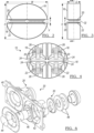
- FIG. 1 is a schematic view of one example of a speaker system 10.
- the speaker system may be mounted in a wall and used in applications in homes, vehicles or other applications where in-wall speakers are utilized.
- the speaker system is a woofer, or subwoofer.
- the term woofer may mean either a subwoofer or a traditional woofer.
- Subwoofers and traditional woofers operate in the bass range.
- the bass range is a low frequency range, which may be around 20 Hertz (Hz) to 400 Hz.
- subwoofers generally emit sound between 20 Hz and 200 Hz
- traditional woofers generally emit sound between 40 Hz and 400 Hz.
- the woofer could be a subwoofer or a traditional woofer.
- the speaker system 10 includes a first pair of transducers 12, a second pair of transducers 14.
- the system 10 includes a speaker housing 16, or enclosure containing the first and second pair of transducers 12, 14 and may be installed inside a wall section. As shown, the enclosure 16 is elliptical shaped. The elliptical shape may minimize the housing space required to mount the speaker system or may be mounted in an existing traditional speaker opening. However, other speaker housing shapes may be utilized.
- transducers may be arranged so that their reaction forces cancel, thereby eliminating mounting point mechanical vibration induced noises.
- acoustic radiation from the rear of the transducer is contained, eliminating mounting surface acoustical vibration induced noises.
- the pairs of transducers 12, 14 are mounted inside the speaker housing 16 such that they face each other and are separated by a slot 18.
- the pairs of transducers 12, 14 each have an upper transducer 20 and a lower transducer 22 that have a diaphragm surface along a front 24 that generates sound by its vibration.
- the upper transducers 20 have acoustic radiation in direction A
- the lower transducers 22 have acoustic radiation in direction B.
- the vibration direction A is equal and opposite the vibration direction B.
- the acoustic radiation A, B from the rear 26 of the transducers is also equal and opposite so that the reaction forces in each pair of transducers 12, 14 cancel each other and minimize undesirable vibration.
- the central axes of acoustic radiation A, B are co-linear.
- the central axis of acoustic radiation is generally perpendicular to the transducer. As such, the pairs of transducers 12, 14 are generally parallel.
- the housing has a width W of approximately 239mm, a height H of approximately 207mm and a depth D of approximately 76mm.
- the woofer speaker system 10 may be housed in a wall only 76mm thick, such as in a vehicle door where the speaker system 10 is concealed by the door trim. Only an opening for the slot 18 would be visible on the vehicle door trim.
- the speaker system 10 may be packaged in a space previously occupied by a traditional speaker.
- One end of the slot 18 is open, defining the front speaker opening 28 of the slot 18.
- the back wall 32, opposite the speaker opening 28, is closed so that sound pressure radiates from the speaker opening 28.
- FIG. 5 illustrates the grill opening 30 in a wall of the speaker system 10 shown in Figures 1-4 .
- the grill opening 30 is approximately the size of the front speaker opening 28 of the slot 18.
- the speaker opening 28 and grill opening 30 may have a width W being approximately 239mm wide and a thickness T of approximately 25mm high.
- the speaker opening 28 and grill opening 30 are defined in a plane generally parallel to the central axis of acoustic radiation of each of the transducers.
- the front 24 of the transducers 20, 22 may extending partially into the slot 18.
- the plane defined by the speaker opening 28 is generally perpendicular to the center longitudinal axis X of the slot, along which the central axes of acoustic radiation A,B intersect. As shown in Figure 1-4 , the front 24 of the transducers 20, 22 may extending partially into the slot 18.
- the wall 34 may include a building wall or a vehicle wall such as a door, rear deck or tailgate, or any other application where the speaker is required to be mounted within a structure.
- the speaker opening 28 of the slot 18 may define the grill opening 30 of the housing 16, as shown in Figure 5 .
- the grill opening 30 may be open or covered with a vented covering 36, such as a fabric or mesh that may additionally provide a decorative exposure to the wall containing the speaker assembly 10.
- FIG. 6 illustrates an example of transducers, such as two upper transducers 20.
- the transducers 20 are mounted to a frame 40 that is secured to the housing 16.
- the frame 40 has openings 42 provided for mounting the transducer components such as the diaphragm assembly 44.
- the transducer illustrated in Figure 6 is an active radiator having a voice coil 46 and magnet assembly 48. However, it is also expected that the speaker systems may similarly include passive radiators or tuned ports.
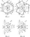
- FIG. 7-10 illustrate slot-loaded speaker arrangements with an odd number of transducers.
- Figure 7 illustrates a speaker assembly 60 having three transducers 62.
- the rear surfaces 66 of each of the transducers are oriented adjacent to each other.
- the front surfaces 68 of each of the transducers are positioned away from each other.
- Each of the three transducers 62 are arranged at an equal angle 70 from each other in a radial array.
- the three transducers are oriented so that the central axes C, D, E of the acoustic radiation are angularly equidistant from each other.
- the central axes C, D, E are oriented at generally 120 degrees from each other.
- the acoustic radiation C, D, E from the rear surfaces 66 intersects at the circumcenter 76 of the housing 74.
- the transducers 62 are disposed within the housing 74.
- the housing 74 is a shaped as a hexagon with one of the transducers mounted on alternating sides of the hexagon. However, the housing could also be triangular, with one of the transducers 62 mounted on each side of the housing.
- the housing 74 forms one side of a rectangular slot 78 along the front surface 68 of each of the transducers 62.
- the speaker assembly 60 would have three grill openings in a wall that correspond to the three rectangular slots 78.
- each transducer 62 is positioned generally perpendicular to the surface of the wall in which the speaker assembly 60 is mounted.
- the slots 78 permit sound pressure radiation from the transducers 62. Alternately, the slots could be removed and the transducers radiate directly. With this configuration, the speaker assembly could be used in a room or vehicle to replace a conventional speaker assembly, while retaining the mechanical and acoustical vibration induced noise reduction benefits.
- Figure 8 illustrates another speaker assembly 80 having three transducers 82.
- the front surfaces 84 of each of the transducers are oriented adjacent and toward each other.
- the rear surfaces 86 of each of the transducers are positioned away from each other.
- Each of the three transducers 82 are arranged at an equidistant angle 88 from each other in a radial array.
- the three transducers are oriented so that the central axes F, G, H of the acoustic radiation are angularly equidistant from each other.
- the central axes F, G, H are oriented at generally 120 degrees from each other.
- the acoustic radiation F, G, H from the front surfaces 84 intersect at the circumcenter 90 of a slot 98.
- the transducers 82 may be mounted in a frame that defines the slot 98.
- the transducers 82 are enclosed in a housing 92.
- the housing 92 may have three sections 94 so that each section 94 houses one of the transducers 82.
- the sections 94 are connected together to form a triangular slot 98.
- the speaker assembly 80 would have a triangular grill opening in a wall that corresponds to the triangular slot 98.
- the diaphragm surfaces of each transducer 82 are positioned perpendicular to the surface of the wall in which the speaker assembly 80 is mounted.
- the triangular slot 98 permits sound pressure radiation from the transducers 82.
- Figure 9 illustrates another speaker assembly 100 having three transducers 82.
- the transducers 82 are mounted to a frame 102 defining the triangular slot 98, but there is no housing covering the rear surfaces 86 of the transducers.
- the rear surface 86 of the transducers is open to the surrounding environment.
- the transducer is considered to operate in an infinite baffle.
- the acoustic radiation J, K, L from the front surfaces 84 intersect at the circumcenter 90 of the frame 102 and slot 98.
- the acoustic radiation J, K, L from the rear surfaces 86 is not contained in an enclosure.
- Some of the benefits of the infinite baffle include: reduction of undesirable increase in resonance frequency of the woofer, reduction of strain on the diaphragm, etc. As a result, the woofer operating in an infinite baffle produces a higher sound pressure level (SPL) at low frequency ranges. Further, without an enclosure, the assembly 100 may be packaged in a smaller space.
- SPL sound pressure level
- Figure 10 illustrates another speaker assembly 110 having three transducers 112, 114, 116.
- the front surfaces 118 of transducer 112 and transducer 114 are oriented adjacent and toward each other.
- Transducer 116 is oriented opposite so that the rear surface 120 is oriented adjacent and toward the front surfaces of transducers 112 and 114.
- the three transducers are oriented so that the central axes Q, R, S of the acoustic radiation are angularly equidistant from each other.
- Each of the three transducers 112, 114, 116 is arranged at an equidistant angle 124 from each other in a radial array based on the central axes Q, R, S.
- the central axes Q, R, S are oriented at generally 120 degrees from each other.
- the acoustic radiation Q, R from the front surface 118 of transducers 112 and 114 and the acoustic radiation S from the rear surface 120 of transducer 116 intersect at the circumcenter 122.
- transducer 116 has reverse polarity in order to effectively cancel the forces and minimize vibration.
- the transducers 112, 114, 116 are mounted to a frame 130 that defines the slot 126.
- the frame 130 forms a slot 126 having a generally triangular shape.
- the speaker assembly 110 would have a grill opening in a wall that corresponds to the slot 126.
- the diaphragm surfaces of each transducer 112, 114, 116 are positioned perpendicular to the surface of the wall in which the speaker assembly 110 is mounted.
- the slot 126 permits sound pressure radiation from the transducers 112, 114, 116.
- the speaker assembly 110 may include a space 128 to allow for movement of the diaphragm of transducer 116.
- the transducers 112 and 114 do not have an enclosure containing the rear surfaces 120.
- the rear surfaces 120 are open to the surrounding environment and are considered to operate in an infinite baffle.
- the transducer 116 does not have an enclosure containing the front surface 118.
- the front surface 118 of transducer 116 is open to the surrounding environment and is also considered to operate in an infinite baffle.
- the rear surface 120 of transducer 116 is disposed within the slot 126.
- the arrangement of the transducers in Figure 10 may allow a compact speaker assembly 110 that can be packaged in small spaces while maintaining optimal bass range performance.
- transducers could also be oriented similarly to Figures 7-10 .
- odd numbers of transducers could also be oriented similarly to Figures 7-10 .
- the central axes of acoustic radiation would be oriented at 72 degrees from each other.
- the central axes of acoustic radiation would be oriented at 40 degrees from each other.
- An even number of transducers could also be oriented similarly to Figures 7-10 .
- four transducers may be arranged in a radial array oriented at 90 degrees from each other so that the central axes of acoustic radiation all intersect and thereby having a square or rectangular shaped slot.
- Example 1 A speaker assembly for being mounted within a wall, the speaker assembly comprising: a housing; a plurality of transducers supported by the housing, each transducer having a front radiation surface and a radiation rear surface adapted to radiate sound along a central axis, wherein the transducers are arranged relative to each other so the central axes of acoustic radiation of each of the transducers intersect at a circumcenter defined between the plurality of transducers to substantially cancel vibrations from the plurality of transducers.
- Example 2 The speaker assembly of example 1, further comprising a slot formed adjacent of each of the transducers, the slot extending a depth dimension of the assembly between a slot opening for transmitting acoustic radiation from the plurality of transducers and a back wall of the housing, wherein the depth dimension is generally perpendicular to the central axes of acoustic radiation of each of the transducers.
- Example 3 The speaker assembly of example 2, wherein a transducer depth is defined between the front radiation surface and the rear radiation surface, wherein the depth dimension of the speaker assembly is less than the transducer depth.
- Example 4 The speaker assembly of example 2, further comprising a plurality of slots, one of the plurality of slots formed along the front radiation surface of each of the plurality of transducers, wherein the rear radiation surfaces of each of the plurality of transducers are positioned adjacent each other.
- Example 5 The speaker assembly of example 2, wherein at least one of the plurality of transducers is positioned so that the rear radiation surface is disposed in the slot.
- Example 6 The speaker assembly of example 2, wherein the slot is defined along the front radiation surface of each of the plurality of transducers.
- Example 7 The speaker assembly of example 2, wherein the slot opening is shaped as an equiangular polygon having generally equal angles between each polygon-side, wherein one of the plurality of transducers is disposed along each polygon-side.
- Example 8 The speaker assembly of example 1, wherein the transducers are arranged in a radial array so the central axes of acoustic radiation are equiangular from each other.
- Example 9 The speaker assembly of example 8, wherein the plurality of transducers comprises an odd number of transducers.
- Example 10 The speaker assembly of example 9, further comprising a slot formed adjacent of each of the transducers, wherein the slot opening is shaped as a triangle.
- Example 11 The speaker assembly of example 1, wherein the housing encloses at least one radiation surface of each of the transducers.
- Example 12 The speaker assembly of example 11, wherein the rear surface of at least one of the transducers is not sealed within the housing thereby defining an infinite baffle.
- Example 13 The speaker assembly of example 2, wherein the slot has a longitudinal center axis along which the central axes of acoustic radiation intersect, wherein the plane of the slot opening is generally perpendicular to the longitudinal center axis of the slot.
- Example 14 The speaker assembly of example 1, wherein the plurality of transducers comprises at least a first and second transducer, wherein the central axes of radiation of the first and second transducer are collinear.
- Example 15 The speaker assembly of example 1, wherein the plurality of transducers comprises a first pair of transducers and a second pair of transducers, wherein the central axes of radiation of the first pair of transducers are collinear; and wherein the central axes of radiation of the second pair of transducers are collinear and parallel to the central axes of radiation of the first pair of transducers.
Landscapes
- Engineering & Computer Science (AREA)
- Physics & Mathematics (AREA)
- Acoustics & Sound (AREA)
- Signal Processing (AREA)
- Health & Medical Sciences (AREA)
- Otolaryngology (AREA)
- Manufacturing & Machinery (AREA)
- General Health & Medical Sciences (AREA)
- Obtaining Desirable Characteristics In Audible-Bandwidth Transducers (AREA)
- Audible-Bandwidth Dynamoelectric Transducers Other Than Pickups (AREA)
- Details Of Audible-Bandwidth Transducers (AREA)
Abstract
Description
- This application claims the benefit of
U.S. provisional application Serial No. 62/287,297 filed January 26, 2016 - The present disclosure generally relates to speakers, and more particularly, to speakers for mounting with a wall mounting.
- Loudspeakers are universally known and utilized in audio systems for the reproduction of sound. In some applications, the speakers are required to be mounted or packaged within a wall, such as a trim panel.
U.S. Patent Nos. 7,840,018 and8,477,966 by Harman International Industries are examples of in-wall speaker systems. - In at least one embodiment, a speaker assembly for being mounted within a wall is provided. The speaker assembly has a housing and a plurality of transducers supported by the housing. Each transducer has a front radiation surface and a radiation rear surface adapted to radiate sound along a central axis. The transducers are arranged relative to each other so the central axes of acoustic radiation of each of the transducers intersect at a circumcenter defined between the plurality of transducers to substantially cancel vibrations from the plurality of transducers.
- In another embodiment, the speaker assembly has a slot formed adjacent of each of the transducers. The slot extends a depth dimension of the assembly between a slot opening for transmitting acoustic radiation from the plurality of transducers and a back wall of the housing, wherein the depth dimension is generally perpendicular to the central axes of acoustic radiation of each of the transducers.
- In a further embodiment, wherein a transducer depth is defined between the front radiation surface and the rear radiation surface, wherein the depth dimension of the speaker assembly is less than the transducer depth.
- In yet another embodiment, the speaker assembly has a plurality of slots, one of the plurality of slots formed along the front radiation surface of each of the plurality of transducers, wherein the rear radiation surfaces of each of the plurality of transducers are positioned adjacent each other.
- In a further embodiment, at least one of the plurality of transducers is positioned so that the rear radiation surface is disposed in the slot.
- In yet another embodiment, the slot is defined along the front radiation of each of the plurality of transducers.
- In another embodiment, the slot opening is shaped as an equiangular polygon having generally equal angles between each polygon-side, wherein one of the plurality of transducers is disposed along each polygon-side.
- In still another embodiment, the transducers are arranged in a radial array so the central axes of radiation are equiangular from each other.
- In a further embodiment, the plurality of transducers comprises an odd number of transducers.
- In yet another embodiment, the slot opening is shaped as a triangle.
- In another embodiment, the housing encloses at least one radiation surface of each of the transducers.
- In a further embodiment, a rear surface of at least one of the transducers is not sealed within the housing thereby defining an infinite baffle.
- In at least one embodiment, a speaker assembly is provided having a frame and a plurality of transducers supported by the frame. Each transducer has a central axis of radiation defined from at least one radiation surface. The frame defines a slot having a slot opening for transmitting the acoustic radiation from the plurality of transducers. The central axes of acoustic radiation of each of the transducers intersect at a center axis of the slot. The slot opening is defined in a plane generally parallel to the central axes of acoustic radiation of each of the transducers.
- In another embodiment, the plane of the slot opening is generally perpendicular to the center longitudinal axis of the slot where the central axes of acoustic radiation of each of the transducers intersect.
- In a further embodiment, the plurality of transducers comprises at least a first and second transducer, wherein the central axes of radiation of the first and second transducer are collinear.
- In yet another embodiment, the plurality of transducers comprises a first pair of transducers and a second pair of transducers. The central axes of radiation of the first pair of transducers are collinear. The central axes of radiation of the second pair of transducers are collinear and parallel to the central axes of radiation of the first pair of transducers.
- In another embodiment, the slot is defined along a front face of each of the plurality of transducers.
- In a further embodiment, each transducer has a front radiation surface and a rear radiation surface, where the slot is positioned along at least one of the front and the rear radiation surface of each transducer.
- In at least one embodiment, a speaker system is provided. A speaker frame is provided for mounting to a wall about an opening. The frame defines a slot having a slot depth extending from a speaker opening to a back wall. A plurality of transducers is mounted to the frame. Each transducer has a central axis of radiation defined from at least one of a front radiation surface and a rear radiation surface. The transducers are oriented so a central axis of acoustic radiation of each of the transducers intersects at a circumcenter defined between the plurality of transducers to substantially cancel vibrations from the plurality of transducers. The slot depth is less than a speaker depth between the front radiation surface and rear radiation surface.
- In a further embodiment, the speaker opening is defined in a plane generally parallel to the central axis of radiation of each of the transducers.
-
-
FIGURE 1 illustrates a schematic view of a vibration cancelling speaker system according to one embodiment of the present disclosure. -
FIGURE 2 illustrates a front perspective view of the speaker system ofFigure 1 . -
FIGURE 3 illustrates a side perspective view of the speaker system ofFigure 2 . -
FIGURE 4 illustrates a section view of the speaker system shown along section 4-4 ofFigure 3 . -
FIGURE 5 illustrates a front view of the speaker system ofFigure 2 when mounted in a wall. -
FIGURE 6 illustrates an exploded view of a transducer. -
FIGURE 7 illustrates a schematic view of a vibration cancelling speaker system according to another embodiment. -
FIGURE 8 illustrates a schematic view of a vibration cancelling speaker system according to another embodiment. -
FIGURE 9 illustrates a schematic view of a vibration cancelling speaker system according to another embodiment. -
FIGURE 10 illustrates a schematic view of a vibration cancelling speaker system according to another embodiment. - As required, detailed embodiments of the present invention are disclosed herein; however, it is to be understood that the disclosed embodiments are merely exemplary of the invention that may be embodied in various and alternative forms. The figures are not necessarily to scale; some features may be exaggerated or minimized to show details of particular components. Therefore, specific structural and functional details disclosed herein are not to be interpreted as limiting, but merely as a representative basis for teaching one skilled in the art to variously employ the present invention.
-
Figure 1 is a schematic view of one example of aspeaker system 10. The speaker system may be mounted in a wall and used in applications in homes, vehicles or other applications where in-wall speakers are utilized. In at least one embodiment, the speaker system is a woofer, or subwoofer. The term woofer may mean either a subwoofer or a traditional woofer. Subwoofers and traditional woofers operate in the bass range. In general, the bass range is a low frequency range, which may be around 20 Hertz (Hz) to 400 Hz. In the bass range, subwoofers generally emit sound between 20 Hz and 200 Hz, and traditional woofers generally emit sound between 40 Hz and 400 Hz. As used herein, the woofer could be a subwoofer or a traditional woofer. - The
speaker system 10 includes a first pair oftransducers 12, a second pair oftransducers 14. Thesystem 10 includes aspeaker housing 16, or enclosure containing the first and second pair oftransducers enclosure 16 is elliptical shaped. The elliptical shape may minimize the housing space required to mount the speaker system or may be mounted in an existing traditional speaker opening. However, other speaker housing shapes may be utilized. - In woofer enclosure design, as the enclosure volume decreases, the moving mass increases. When the enclosure volume becomes very small, the moving mass becomes very large. The acceleration of this moving mass during transducer operation generates an action force proportional to the mass and acceleration. The sound pressure level (SPL) is proportional to the acceleration, so small enclosures producing a high SPL generate significant action forces. These forces are reflected onto the enclosure mounting points of the transducers as reaction forces. The force on these mounting points can cause mechanical vibrations on the surfaces they are attached to. Sound pressure level (SPL) airflow can also cause mechanical vibrations of the surfaces in the vicinity of the transducer mounting. These mechanical vibrations can cause the surfaces to produce audible noises, which are undesirable.
- Multiple transducers may be arranged so that their reaction forces cancel, thereby eliminating mounting point mechanical vibration induced noises. By mounting the transducers in enclosures, acoustic radiation from the rear of the transducer is contained, eliminating mounting surface acoustical vibration induced noises.
- The pairs of
transducers speaker housing 16 such that they face each other and are separated by aslot 18. The pairs oftransducers upper transducer 20 and alower transducer 22 that have a diaphragm surface along a front 24 that generates sound by its vibration. Theupper transducers 20 have acoustic radiation in direction A, while thelower transducers 22 have acoustic radiation in direction B. The vibration direction A is equal and opposite the vibration direction B. By slot-loading the transducers, acoustic radiation A, B from thefront 24 of each of the transducers can be better controlled, eliminating grill surface acoustical vibration induced noises. Further, the acoustic radiation A, B from the rear 26 of the transducers is also equal and opposite so that the reaction forces in each pair oftransducers transducers - Further by slot-loading the transducers, new form factors or aspect ratios can be realized, allowing transducer placement in areas that were previously unfeasible. In one example, shown in
Figures 1-4 , the housing has a width W of approximately 239mm, a height H of approximately 207mm and a depth D of approximately 76mm. In this example, thewoofer speaker system 10 may be housed in a wall only 76mm thick, such as in a vehicle door where thespeaker system 10 is concealed by the door trim. Only an opening for theslot 18 would be visible on the vehicle door trim. In this example, thespeaker system 10 may be packaged in a space previously occupied by a traditional speaker. - One end of the
slot 18 is open, defining the front speaker opening 28 of theslot 18. Theback wall 32, opposite thespeaker opening 28, is closed so that sound pressure radiates from thespeaker opening 28. - Slot-loading also minimizes effective radiating area, allowing smaller grill openings, enabling even more transducer placement options and industrial design flexibility. For example,
Figure 5 illustrates thegrill opening 30 in a wall of thespeaker system 10 shown inFigures 1-4 . Thegrill opening 30 is approximately the size of the front speaker opening 28 of theslot 18. In the example shown inFigures 1-4 , thespeaker opening 28 andgrill opening 30 may have a width W being approximately 239mm wide and a thickness T of approximately 25mm high. Thespeaker opening 28 andgrill opening 30 are defined in a plane generally parallel to the central axis of acoustic radiation of each of the transducers. As shown inFigure 1-4 , thefront 24 of thetransducers slot 18. Further, the plane defined by thespeaker opening 28 is generally perpendicular to the center longitudinal axis X of the slot, along which the central axes of acoustic radiation A,B intersect. As shown inFigure 1-4 , thefront 24 of thetransducers slot 18. - The
wall 34 may include a building wall or a vehicle wall such as a door, rear deck or tailgate, or any other application where the speaker is required to be mounted within a structure. - When installed in a
wall 34, the speaker opening 28 of theslot 18 may define thegrill opening 30 of thehousing 16, as shown inFigure 5 . Thegrill opening 30 may be open or covered with a vented covering 36, such as a fabric or mesh that may additionally provide a decorative exposure to the wall containing thespeaker assembly 10. -
Figure 6 illustrates an example of transducers, such as twoupper transducers 20. Thetransducers 20 are mounted to aframe 40 that is secured to thehousing 16. Theframe 40 hasopenings 42 provided for mounting the transducer components such as thediaphragm assembly 44. The transducer illustrated inFigure 6 is an active radiator having avoice coil 46 andmagnet assembly 48. However, it is also expected that the speaker systems may similarly include passive radiators or tuned ports. - Slot-loading also allows even more transducer placement options and industrial design flexibility.
Figures 7-10 illustrate slot-loaded speaker arrangements with an odd number of transducers. -
Figure 7 illustrates aspeaker assembly 60 having threetransducers 62. The rear surfaces 66 of each of the transducers are oriented adjacent to each other. The front surfaces 68 of each of the transducers are positioned away from each other. Each of the threetransducers 62 are arranged at anequal angle 70 from each other in a radial array. As shown inFigure 7 , the three transducers are oriented so that the central axes C, D, E of the acoustic radiation are angularly equidistant from each other. In this example with three transducers, the central axes C, D, E are oriented at generally 120 degrees from each other. The acoustic radiation C, D, E from therear surfaces 66 intersects at thecircumcenter 76 of thehousing 74. - As illustrated in
Figure 7 , thetransducers 62 are disposed within thehousing 74. Thehousing 74 is a shaped as a hexagon with one of the transducers mounted on alternating sides of the hexagon. However, the housing could also be triangular, with one of thetransducers 62 mounted on each side of the housing. Thehousing 74 forms one side of arectangular slot 78 along thefront surface 68 of each of thetransducers 62. Thespeaker assembly 60 would have three grill openings in a wall that correspond to the threerectangular slots 78. - The diaphragm surfaces of each
transducer 62 are positioned generally perpendicular to the surface of the wall in which thespeaker assembly 60 is mounted. Theslots 78 permit sound pressure radiation from thetransducers 62. Alternately, the slots could be removed and the transducers radiate directly. With this configuration, the speaker assembly could be used in a room or vehicle to replace a conventional speaker assembly, while retaining the mechanical and acoustical vibration induced noise reduction benefits. -
Figure 8 illustrates anotherspeaker assembly 80 having threetransducers 82. The front surfaces 84 of each of the transducers are oriented adjacent and toward each other. The rear surfaces 86 of each of the transducers are positioned away from each other. Each of the threetransducers 82 are arranged at anequidistant angle 88 from each other in a radial array. As shown inFigure 8 , the three transducers are oriented so that the central axes F, G, H of the acoustic radiation are angularly equidistant from each other. In this example with three transducers, the central axes F, G, H are oriented at generally 120 degrees from each other. The acoustic radiation F, G, H from thefront surfaces 84 intersect at thecircumcenter 90 of aslot 98. Thetransducers 82 may be mounted in a frame that defines theslot 98. - As illustrated in
Figure 8 , thetransducers 82 are enclosed in ahousing 92. Thehousing 92 may have threesections 94 so that eachsection 94 houses one of thetransducers 82. Thesections 94 are connected together to form atriangular slot 98. Thespeaker assembly 80 would have a triangular grill opening in a wall that corresponds to thetriangular slot 98. The diaphragm surfaces of eachtransducer 82 are positioned perpendicular to the surface of the wall in which thespeaker assembly 80 is mounted. Thetriangular slot 98 permits sound pressure radiation from thetransducers 82. - Similar to
Figure 8, Figure 9 illustrates anotherspeaker assembly 100 having threetransducers 82. In the embodiment inFigure 9 , thetransducers 82 are mounted to aframe 102 defining thetriangular slot 98, but there is no housing covering therear surfaces 86 of the transducers. Therear surface 86 of the transducers is open to the surrounding environment. When the transducer is not within an housing, like inFigure 9 , the transducer is considered to operate in an infinite baffle. The acoustic radiation J, K, L from thefront surfaces 84 intersect at thecircumcenter 90 of theframe 102 andslot 98. The acoustic radiation J, K, L from therear surfaces 86 is not contained in an enclosure. - Some of the benefits of the infinite baffle include: reduction of undesirable increase in resonance frequency of the woofer, reduction of strain on the diaphragm, etc. As a result, the woofer operating in an infinite baffle produces a higher sound pressure level (SPL) at low frequency ranges. Further, without an enclosure, the
assembly 100 may be packaged in a smaller space. -
Figure 10 illustrates anotherspeaker assembly 110 having threetransducers front surfaces 118 oftransducer 112 andtransducer 114 are oriented adjacent and toward each other.Transducer 116 is oriented opposite so that therear surface 120 is oriented adjacent and toward the front surfaces oftransducers - As shown in
Figure 10 , the three transducers are oriented so that the central axes Q, R, S of the acoustic radiation are angularly equidistant from each other. Each of the threetransducers equidistant angle 124 from each other in a radial array based on the central axes Q, R, S. In this example with three transducers, the central axes Q, R, S are oriented at generally 120 degrees from each other. The acoustic radiation Q, R from thefront surface 118 oftransducers rear surface 120 oftransducer 116 intersect at the circumcenter 122. In the speaker arrangement inFigure 10 ,transducer 116 has reverse polarity in order to effectively cancel the forces and minimize vibration. - In the embodiment illustrated in
Figure 10 , thetransducers frame 130 that defines theslot 126. Theframe 130 forms aslot 126 having a generally triangular shape. Thespeaker assembly 110 would have a grill opening in a wall that corresponds to theslot 126. The diaphragm surfaces of eachtransducer speaker assembly 110 is mounted. Theslot 126 permits sound pressure radiation from thetransducers speaker assembly 110 may include aspace 128 to allow for movement of the diaphragm oftransducer 116. - The
transducers rear surfaces 120 are open to the surrounding environment and are considered to operate in an infinite baffle. Thetransducer 116 does not have an enclosure containing thefront surface 118. Thefront surface 118 oftransducer 116 is open to the surrounding environment and is also considered to operate in an infinite baffle. Therear surface 120 oftransducer 116 is disposed within theslot 126. The arrangement of the transducers inFigure 10 may allow acompact speaker assembly 110 that can be packaged in small spaces while maintaining optimal bass range performance. - Other numbers of transducers could also be oriented similarly to
Figures 7-10 . In particular, odd numbers of transducers could also be oriented similarly toFigures 7-10 . For example, if there were five transducers, the central axes of acoustic radiation would be oriented at 72 degrees from each other. Similarly, in a woofer assembly having nine transducers, the central axes of acoustic radiation would be oriented at 40 degrees from each other. An even number of transducers could also be oriented similarly toFigures 7-10 . For example, four transducers may be arranged in a radial array oriented at 90 degrees from each other so that the central axes of acoustic radiation all intersect and thereby having a square or rectangular shaped slot. - While exemplary embodiments are described above, it is not intended that these embodiments describe all possible forms of the invention. Rather, the words used in the specification are words of description rather than limitation, and it is understood that various changes may be made without departing from the spirit and scope of the invention. Additionally, the features of various implementing embodiments may be combined to form further embodiments of the invention.
- Although the present disclosure is not so limited, the following numbered examples demonstrate one or more aspects of the disclosure.
- Example 1. A speaker assembly for being mounted within a wall, the speaker assembly comprising: a housing; a plurality of transducers supported by the housing, each transducer having a front radiation surface and a radiation rear surface adapted to radiate sound along a central axis, wherein the transducers are arranged relative to each other so the central axes of acoustic radiation of each of the transducers intersect at a circumcenter defined between the plurality of transducers to substantially cancel vibrations from the plurality of transducers.
- Example 2. The speaker assembly of example 1, further comprising a slot formed adjacent of each of the transducers, the slot extending a depth dimension of the assembly between a slot opening for transmitting acoustic radiation from the plurality of transducers and a back wall of the housing, wherein the depth dimension is generally perpendicular to the central axes of acoustic radiation of each of the transducers.
- Example 3. The speaker assembly of example 2, wherein a transducer depth is defined between the front radiation surface and the rear radiation surface, wherein the depth dimension of the speaker assembly is less than the transducer depth.
- Example 4. The speaker assembly of example 2, further comprising a plurality of slots, one of the plurality of slots formed along the front radiation surface of each of the plurality of transducers, wherein the rear radiation surfaces of each of the plurality of transducers are positioned adjacent each other.
- Example 5. The speaker assembly of example 2, wherein at least one of the plurality of transducers is positioned so that the rear radiation surface is disposed in the slot.
- Example 6. The speaker assembly of example 2, wherein the slot is defined along the front radiation surface of each of the plurality of transducers.
- Example 7. The speaker assembly of example 2, wherein the slot opening is shaped as an equiangular polygon having generally equal angles between each polygon-side, wherein one of the plurality of transducers is disposed along each polygon-side.
- Example 8. The speaker assembly of example 1, wherein the transducers are arranged in a radial array so the central axes of acoustic radiation are equiangular from each other.
- Example 9. The speaker assembly of example 8, wherein the plurality of transducers comprises an odd number of transducers.
- Example 10. The speaker assembly of example 9, further comprising a slot formed adjacent of each of the transducers, wherein the slot opening is shaped as a triangle.
- Example 11. The speaker assembly of example 1, wherein the housing encloses at least one radiation surface of each of the transducers.
- Example 12. The speaker assembly of example 11, wherein the rear surface of at least one of the transducers is not sealed within the housing thereby defining an infinite baffle.
- Example 13. The speaker assembly of example 2, wherein the slot has a longitudinal center axis along which the central axes of acoustic radiation intersect, wherein the plane of the slot opening is generally perpendicular to the longitudinal center axis of the slot.
- Example 14. The speaker assembly of example 1, wherein the plurality of transducers comprises at least a first and second transducer, wherein the central axes of radiation of the first and second transducer are collinear.
- Example 15. The speaker assembly of example 1, wherein the plurality of transducers comprises a first pair of transducers and a second pair of transducers, wherein the central axes of radiation of the first pair of transducers are collinear; and wherein the central axes of radiation of the second pair of transducers are collinear and parallel to the central axes of radiation of the first pair of transducers.
Claims (15)
- A speaker assembly comprising:a housing;a plurality of transducers supported by the housing, each transducer having a front radiation surface and a radiation rear surface adapted to radiate sound along a central axis, wherein a transducer depth is defined between the front radiation surface and rear radiation surface,at least one slot formed in the housing and having a slot opening in the housing for transmitting acoustic radiation from the plurality of transducers, the slot extending a depth dimension of the assembly between the slot opening and a back wall of the housing,wherein the transducer depth is defined between the front radiation surface and the rear radiation surface, wherein the depth dimension of the speaker assembly is less than the transducer depth,wherein the depth dimension is generally perpendicular to the central axes of acoustic radiation of each of the transducers.
- The speaker assembly of claim 1, wherein at least one of the front radiation surface or the rear radiation surface of each the transducers is open to the slot.
- The speaker assembly of claim 1, wherein the at least one slot comprises a plurality of slots, one of the plurality of slots formed along the front radiation surface of each of the plurality of transducers.
- The speaker assembly of claim 1, wherein at least one of the plurality of transducers is positioned so that the rear radiation surface is open to the slot.
- The speaker assembly of claim 1, wherein the slot is defined along the front radiation surface of each of the plurality of transducers.
- The speaker assembly of claim 1, wherein the slot opening is shaped as an equiangular polygon having generally equal angles between each polygon-side, wherein one of the plurality of transducers is disposed along each polygon-side.
- The speaker assembly of claim 1, wherein the transducers are arranged in a radial array so the central axes of acoustic radiation are equiangular from each other.
- The speaker assembly of claim 1, wherein the housing encloses at least one of the front or rear radiation surface of each of the transducers, and the other of the front or rear radiation surfaces of each of the transducers is open to the slot.
- The speaker assembly of claim 1, wherein the rear surface of at least one of the transducers is not sealed within the housing thereby defining an infinite baffle.
- The speaker assembly of claim 1, wherein the central axes of acoustic radiation of each of the transducers intersect at a longitudinal center axis of the slot.
- The speaker assembly of claim 10, wherein a plane of the slot opening is generally perpendicular to the longitudinal center axis of the slot.
- The speaker assembly of claim 1, wherein the plurality of transducers comprises at least a first and second transducer, wherein the central axes of radiation of the first and second transducer are collinear.
- The speaker assembly of claim 1, wherein the plurality of transducers comprises a first pair of transducers and a second pair of transducers,wherein the central axes of radiation of the first pair of transducers are collinear; andwherein the central axes of radiation of the second pair of transducers are collinear and parallel to the central axes of radiation of the first pair of transducers.
- The speaker assembly of claim 1, wherein the slot is defined along a front face of each of the plurality of transducers.
- The speaker assembly of claim 1, wherein each transducer has a front radiation surface and a rear radiation surface, where the slot is positioned along at least one of the front and the rear radiation surface of each transducer.
Applications Claiming Priority (3)
| Application Number | Priority Date | Filing Date | Title |
|---|---|---|---|
| US201662287297P | 2016-01-26 | 2016-01-26 | |
| PCT/US2017/015028 WO2017132313A1 (en) | 2016-01-26 | 2017-01-26 | Vibration cancelling speaker arrangement |
| EP17744866.9A EP3409022A4 (en) | 2016-01-26 | 2017-01-26 | VIBRATION CANCELLATION SPEAKER ARRANGEMENT |
Related Parent Applications (1)
| Application Number | Title | Priority Date | Filing Date |
|---|---|---|---|
| EP17744866.9A Division EP3409022A4 (en) | 2016-01-26 | 2017-01-26 | VIBRATION CANCELLATION SPEAKER ARRANGEMENT |
Publications (2)
| Publication Number | Publication Date |
|---|---|
| EP4460039A2 true EP4460039A2 (en) | 2024-11-06 |
| EP4460039A3 EP4460039A3 (en) | 2025-04-16 |
Family
ID=59398882
Family Applications (2)
| Application Number | Title | Priority Date | Filing Date |
|---|---|---|---|
| EP17744866.9A Ceased EP3409022A4 (en) | 2016-01-26 | 2017-01-26 | VIBRATION CANCELLATION SPEAKER ARRANGEMENT |
| EP24182308.7A Pending EP4460039A3 (en) | 2016-01-26 | 2017-01-26 | Vibration cancelling speaker arrangement |
Family Applications Before (1)
| Application Number | Title | Priority Date | Filing Date |
|---|---|---|---|
| EP17744866.9A Ceased EP3409022A4 (en) | 2016-01-26 | 2017-01-26 | VIBRATION CANCELLATION SPEAKER ARRANGEMENT |
Country Status (4)
| Country | Link |
|---|---|
| US (2) | US10652638B2 (en) |
| EP (2) | EP3409022A4 (en) |
| CN (1) | CN208987110U (en) |
| WO (1) | WO2017132313A1 (en) |
Families Citing this family (4)
| Publication number | Priority date | Publication date | Assignee | Title |
|---|---|---|---|---|
| US10652638B2 (en) | 2016-01-26 | 2020-05-12 | Harman International Industries, Incorporated | Vibration cancelling speaker arrangement |
| US11716563B2 (en) * | 2020-06-15 | 2023-08-01 | Bose Corporation | Portable loudspeaker systems |
| US12177625B2 (en) | 2021-09-14 | 2024-12-24 | Panduit Corp. | High performance loudspeaker assembly |
| US20260107084A1 (en) | 2024-10-16 | 2026-04-16 | Alps Alpine Co., Ltd. | Dual-opposed inverted transducer assembly |
Citations (1)
| Publication number | Priority date | Publication date | Assignee | Title |
|---|---|---|---|---|
| US7840018B2 (en) | 2006-09-30 | 2010-11-23 | Harman International Industries, Incorporated | In-wall sub-woofer system with high-volume displacement |
Family Cites Families (31)
| Publication number | Priority date | Publication date | Assignee | Title |
|---|---|---|---|---|
| US2544742A (en) * | 1946-12-31 | 1951-03-13 | Vibra Sonic Inc | Cubic loud-speaker cabinet |
| US3393764A (en) * | 1966-12-27 | 1968-07-23 | Curtiss R. Schafer | Loudspeaker systems |
| US3688864A (en) * | 1970-04-16 | 1972-09-05 | Talbot American Corp | Infinite dynamic damping loudspeaker systems |
| DE2725346C3 (en) * | 1977-06-04 | 1981-05-14 | Josef Wilhelm 8725 Arnstein Manger | speaker |
| US4733749A (en) | 1986-02-26 | 1988-03-29 | Electro-Voice, Inc. | High output loudspeaker for low frequency reproduction |
| US5097514A (en) * | 1988-05-25 | 1992-03-17 | Mcneill Dennis G | Equilateral tetrahedral speaker system |
| JP2673002B2 (en) * | 1989-03-31 | 1997-11-05 | 株式会社ケンウッド | Speaker system |
| TW203674B (en) | 1991-07-09 | 1993-04-11 | Tong Hoon Sohn | |
| US5561717A (en) * | 1994-03-15 | 1996-10-01 | American Trading And Production Corporation | Loudspeaker system |
| US5619581A (en) | 1994-05-18 | 1997-04-08 | Lord Corporation | Active noise and vibration cancellation system |
| US6628792B1 (en) | 1998-03-30 | 2003-09-30 | Paul W. Paddock | Back to back mounted compound woofer with compression/bandpass loading |
| US7324654B2 (en) * | 2000-07-31 | 2008-01-29 | Harman International Industries, Inc. | Arbitrary coverage angle sound integrator |
| DE60208245T2 (en) * | 2001-01-22 | 2006-07-13 | Matsushita Electric Industrial Co., Ltd., Kadoma | Speaker System |
| US7433483B2 (en) | 2001-02-09 | 2008-10-07 | Thx Ltd. | Narrow profile speaker configurations and systems |
| FR2824990B1 (en) | 2001-05-15 | 2003-09-26 | Jean Pierre Morkerken | SOUND TRANSMITTER AND SPEAKER |
| US6985593B2 (en) | 2002-08-23 | 2006-01-10 | Bose Corporation | Baffle vibration reducing |
| US7551749B2 (en) | 2002-08-23 | 2009-06-23 | Bose Corporation | Baffle vibration reducing |
| US7499555B1 (en) * | 2002-12-02 | 2009-03-03 | Plantronics, Inc. | Personal communication method and apparatus with acoustic stray field cancellation |
| US7133533B2 (en) * | 2003-07-21 | 2006-11-07 | Bose Corporation | Passive acoustic radiating |
| WO2009050909A1 (en) | 2007-10-19 | 2009-04-23 | Kazumichi Imai | Recoilless speaker unit |
| JPWO2009078164A1 (en) * | 2007-12-18 | 2011-04-28 | パナソニック株式会社 | Speaker device with directivity adjustment panel |
| US8189841B2 (en) | 2008-03-27 | 2012-05-29 | Bose Corporation | Acoustic passive radiating |
| US8180076B2 (en) | 2008-07-31 | 2012-05-15 | Bose Corporation | System and method for reducing baffle vibration |
| US8259983B2 (en) * | 2009-08-31 | 2012-09-04 | Eugen Nedelcu | Anti-vibration in-ceiling speaker system |
| GB2491108B (en) | 2011-05-18 | 2014-06-04 | Gp Acoustics Uk Ltd | Loudspeaker |
| US8798308B2 (en) | 2012-02-21 | 2014-08-05 | Bose Corporation | Convective airflow using a passive radiator |
| US9055370B2 (en) | 2012-08-31 | 2015-06-09 | Bose Corporation | Vibration-reducing passive radiators |
| US20140114249A1 (en) | 2012-10-19 | 2014-04-24 | Meyers & Gerard Medical Llc | Self contained self inflating regulated container |
| WO2014164573A1 (en) | 2013-03-13 | 2014-10-09 | Thx Ltd | Slim profile loudspeaker |
| US10341763B2 (en) | 2015-04-02 | 2019-07-02 | Harman International Industries, Incorporated | Passive radiator assembly |
| US10652638B2 (en) | 2016-01-26 | 2020-05-12 | Harman International Industries, Incorporated | Vibration cancelling speaker arrangement |
-
2017
- 2017-01-26 US US16/072,030 patent/US10652638B2/en active Active
- 2017-01-26 CN CN201790000530.3U patent/CN208987110U/en active Active
- 2017-01-26 WO PCT/US2017/015028 patent/WO2017132313A1/en not_active Ceased
- 2017-01-26 EP EP17744866.9A patent/EP3409022A4/en not_active Ceased
- 2017-01-26 EP EP24182308.7A patent/EP4460039A3/en active Pending
-
2020
- 2020-04-08 US US16/843,478 patent/US11082760B2/en active Active
Patent Citations (2)
| Publication number | Priority date | Publication date | Assignee | Title |
|---|---|---|---|---|
| US7840018B2 (en) | 2006-09-30 | 2010-11-23 | Harman International Industries, Incorporated | In-wall sub-woofer system with high-volume displacement |
| US8477966B2 (en) | 2006-09-30 | 2013-07-02 | Harman International Industries, Incorporated | In-wall sub-woofer with high-volume displacement |
Also Published As
| Publication number | Publication date |
|---|---|
| EP3409022A4 (en) | 2019-09-18 |
| EP3409022A1 (en) | 2018-12-05 |
| US20190037295A1 (en) | 2019-01-31 |
| US11082760B2 (en) | 2021-08-03 |
| WO2017132313A1 (en) | 2017-08-03 |
| EP4460039A3 (en) | 2025-04-16 |
| US10652638B2 (en) | 2020-05-12 |
| CN208987110U (en) | 2019-06-14 |
| US20200236450A1 (en) | 2020-07-23 |
Similar Documents
| Publication | Publication Date | Title |
|---|---|---|
| US9924263B2 (en) | Slim profile loudspeaker | |
| US11082760B2 (en) | Vibration cancelling speaker arrangement | |
| JP4468364B2 (en) | Module for use in acoustic devices and acoustic enclosures | |
| JP5405598B2 (en) | Speaker | |
| EP3646616B1 (en) | Electro-acoustical transducer arrangements of a sound system | |
| US8477966B2 (en) | In-wall sub-woofer with high-volume displacement | |
| JPH02260899A (en) | Nondirectional acoustic transducer and speaker system | |
| WO2008064294A2 (en) | Passive acoustical radiating | |
| WO2017210605A1 (en) | Passive cardioid speaker | |
| CN108781315B (en) | Loudspeaker modules with different module housing geometries and similar acoustic properties | |
| JP2021016111A (en) | Speaker cabinet and speaker system | |
| EP4465657A1 (en) | Directional loudspeaker | |
| KR102873114B1 (en) | loudspeaker device | |
| US20230135696A1 (en) | Acoustic Transducer Arrangement and Method for Operating an Acoustic Transducer Arrangement | |
| JP2010193228A (en) | Speaker system | |
| JP2020178146A (en) | Ceiling embedded speaker | |
| JP2020178147A (en) | Ceiling embedded speaker | |
| HK40017054A (en) | Electro-acoustical transducer arrangements of a sound system | |
| HK1225886A1 (en) | Slim profile loudspeaker |
Legal Events
| Date | Code | Title | Description |
|---|---|---|---|
| PUAI | Public reference made under article 153(3) epc to a published international application that has entered the european phase |
Free format text: ORIGINAL CODE: 0009012 |
|
| STAA | Information on the status of an ep patent application or granted ep patent |
Free format text: STATUS: THE APPLICATION HAS BEEN PUBLISHED |
|
| AC | Divisional application: reference to earlier application |
Ref document number: 3409022 Country of ref document: EP Kind code of ref document: P |
|
| AK | Designated contracting states |
Kind code of ref document: A2 Designated state(s): AL AT BE BG CH CY CZ DE DK EE ES FI FR GB GR HR HU IE IS IT LI LT LU LV MC MK MT NL NO PL PT RO RS SE SI SK SM TR |
|
| REG | Reference to a national code |
Ref country code: DE Ref legal event code: R079 Free format text: PREVIOUS MAIN CLASS: H04R0001400000 Ipc: H04R0001020000 |
|
| PUAL | Search report despatched |
Free format text: ORIGINAL CODE: 0009013 |
|
| AK | Designated contracting states |
Kind code of ref document: A3 Designated state(s): AL AT BE BG CH CY CZ DE DK EE ES FI FR GB GR HR HU IE IS IT LI LT LU LV MC MK MT NL NO PL PT RO RS SE SI SK SM TR |
|
| RIC1 | Information provided on ipc code assigned before grant |
Ipc: H04R 1/40 20060101ALI20250312BHEP Ipc: H04R 1/32 20060101ALI20250312BHEP Ipc: H04R 1/28 20060101ALI20250312BHEP Ipc: H04R 1/26 20060101ALI20250312BHEP Ipc: H04R 1/02 20060101AFI20250312BHEP |
|
| STAA | Information on the status of an ep patent application or granted ep patent |
Free format text: STATUS: REQUEST FOR EXAMINATION WAS MADE |
|
| 17P | Request for examination filed |
Effective date: 20251016 |
|
| STAA | Information on the status of an ep patent application or granted ep patent |
Free format text: STATUS: EXAMINATION IS IN PROGRESS |
|
| 17Q | First examination report despatched |
Effective date: 20260130 |