EP4459914A1 - Verfahren und vorrichtung zur uplink-übertragung in einem drahtloskommunikationssystem - Google Patents
Verfahren und vorrichtung zur uplink-übertragung in einem drahtloskommunikationssystem Download PDFInfo
- Publication number
- EP4459914A1 EP4459914A1 EP24171611.7A EP24171611A EP4459914A1 EP 4459914 A1 EP4459914 A1 EP 4459914A1 EP 24171611 A EP24171611 A EP 24171611A EP 4459914 A1 EP4459914 A1 EP 4459914A1
- Authority
- EP
- European Patent Office
- Prior art keywords
- uci
- uto
- harq
- information
- pusch
- Prior art date
- Legal status (The legal status is an assumption and is not a legal conclusion. Google has not performed a legal analysis and makes no representation as to the accuracy of the status listed.)
- Pending
Links
- 230000005540 biological transmission Effects 0.000 title claims abstract description 186
- 238000000034 method Methods 0.000 title claims abstract description 162
- 238000004891 communication Methods 0.000 title claims abstract description 55
- 230000008569 process Effects 0.000 description 46
- 238000010295 mobile communication Methods 0.000 description 13
- 238000010586 diagram Methods 0.000 description 12
- 230000006870 function Effects 0.000 description 10
- 230000011664 signaling Effects 0.000 description 9
- FFBHFFJDDLITSX-UHFFFAOYSA-N benzyl N-[2-hydroxy-4-(3-oxomorpholin-4-yl)phenyl]carbamate Chemical compound OC1=C(NC(=O)OCC2=CC=CC=C2)C=CC(=C1)N1CCOCC1=O FFBHFFJDDLITSX-UHFFFAOYSA-N 0.000 description 8
- 101000741965 Homo sapiens Inactive tyrosine-protein kinase PRAG1 Proteins 0.000 description 7
- 102100038659 Inactive tyrosine-protein kinase PRAG1 Human genes 0.000 description 7
- 238000005516 engineering process Methods 0.000 description 6
- 230000004044 response Effects 0.000 description 6
- 241001175904 Labeo bata Species 0.000 description 5
- 238000012545 processing Methods 0.000 description 5
- 238000001228 spectrum Methods 0.000 description 5
- 230000004913 activation Effects 0.000 description 4
- 101150069124 RAN1 gene Proteins 0.000 description 3
- 101100355633 Salmo salar ran gene Proteins 0.000 description 3
- 230000003190 augmentative effect Effects 0.000 description 3
- 125000004122 cyclic group Chemical group 0.000 description 3
- 230000001965 increasing effect Effects 0.000 description 3
- 238000003780 insertion Methods 0.000 description 3
- 230000037431 insertion Effects 0.000 description 3
- 230000007774 longterm Effects 0.000 description 3
- 230000000737 periodic effect Effects 0.000 description 3
- 230000007704 transition Effects 0.000 description 3
- 238000013473 artificial intelligence Methods 0.000 description 2
- 230000001413 cellular effect Effects 0.000 description 2
- 230000008859 change Effects 0.000 description 2
- 239000000470 constituent Substances 0.000 description 2
- 230000002708 enhancing effect Effects 0.000 description 2
- 238000013507 mapping Methods 0.000 description 2
- 230000003252 repetitive effect Effects 0.000 description 2
- 238000012546 transfer Methods 0.000 description 2
- 101150074586 RAN3 gene Proteins 0.000 description 1
- 238000012937 correction Methods 0.000 description 1
- 230000009849 deactivation Effects 0.000 description 1
- 230000009977 dual effect Effects 0.000 description 1
- 238000005259 measurement Methods 0.000 description 1
- 230000007246 mechanism Effects 0.000 description 1
- 238000012827 research and development Methods 0.000 description 1
- 230000002441 reversible effect Effects 0.000 description 1
- 230000008054 signal transmission Effects 0.000 description 1
- 230000002123 temporal effect Effects 0.000 description 1
Images


Classifications
-
- H—ELECTRICITY
- H04—ELECTRIC COMMUNICATION TECHNIQUE
- H04L—TRANSMISSION OF DIGITAL INFORMATION, e.g. TELEGRAPHIC COMMUNICATION
- H04L1/00—Arrangements for detecting or preventing errors in the information received
- H04L1/12—Arrangements for detecting or preventing errors in the information received by using return channel
- H04L1/16—Arrangements for detecting or preventing errors in the information received by using return channel in which the return channel carries supervisory signals, e.g. repetition request signals
- H04L1/18—Automatic repetition systems, e.g. Van Duuren systems
- H04L1/1829—Arrangements specially adapted for the receiver end
- H04L1/1861—Physical mapping arrangements
-
- H—ELECTRICITY
- H04—ELECTRIC COMMUNICATION TECHNIQUE
- H04L—TRANSMISSION OF DIGITAL INFORMATION, e.g. TELEGRAPHIC COMMUNICATION
- H04L1/00—Arrangements for detecting or preventing errors in the information received
- H04L1/12—Arrangements for detecting or preventing errors in the information received by using return channel
- H04L1/16—Arrangements for detecting or preventing errors in the information received by using return channel in which the return channel carries supervisory signals, e.g. repetition request signals
- H04L1/18—Automatic repetition systems, e.g. Van Duuren systems
- H04L1/1829—Arrangements specially adapted for the receiver end
- H04L1/1854—Scheduling and prioritising arrangements
-
- H—ELECTRICITY
- H04—ELECTRIC COMMUNICATION TECHNIQUE
- H04L—TRANSMISSION OF DIGITAL INFORMATION, e.g. TELEGRAPHIC COMMUNICATION
- H04L1/00—Arrangements for detecting or preventing errors in the information received
- H04L1/12—Arrangements for detecting or preventing errors in the information received by using return channel
- H04L1/16—Arrangements for detecting or preventing errors in the information received by using return channel in which the return channel carries supervisory signals, e.g. repetition request signals
- H04L1/1607—Details of the supervisory signal
- H04L1/1671—Details of the supervisory signal the supervisory signal being transmitted together with control information
Definitions
- the present disclosure relates to a 5 th generation new radio (5G NR) system based on the 3 rd generation partnership project (3GPP).
- 5G NR 5 th generation new radio
- 3GPP 3 rd generation partnership project
- next generation 5G system which is an enhanced mobile broadband communication system compared to the exiting LTE system, has become necessary.
- eMBB Enhanced Mobile BroadBand
- URLLC Ultra-reliability and low-latency communication
- mMTC Massive Machine-Type Communications
- eMBB is characterized by high spectrum efficiency, high user experienced data rate, high peak data.
- URLLC is characterized by ultra-reliable, ultra-low latency, ultra-high availability (e.g., vehicle-to-everything (V2X), Emergency Service, Remote Control).
- mMTC is characterized by low cost, low energy, short packet, and massive connectivity (e.g., Internet of Things (IoT)).
- IoT Internet of Things
- the disclosure provides a method and apparatus for controlling uplink transmission in a wireless communication system.
- the disclosure provides a method and apparatus for performing efficient uplink transmission through a configured physical uplink shared channel (PUSCH) when PUSCH transmission is configured.
- PUSCH physical uplink shared channel
- a method of a terminal for configuring a physical uplink shared channel (PUSCH) in a wireless communication system may include configuring unused transmission occasion (UTO) - uplink control information (UCI) for indicating an unused transmission occasion of the PUSCH, transmitting the UTO-UCI and hybrid automatic repeat and request (HARQ) information together through the PUSCH, wherein the UTO-UCI and the HARQ are transmitted together based on a first priority of the HARQ information.
- UTO transmission occasion
- HARQ hybrid automatic repeat and request
- a method of a base station for performing configuration for a physical uplink shared channel (PUSCH) to a terminal in a wireless communication system may include configuring and transmitting unused transmission occasion (UTO)-uplink control information (UCI) for indicating an unused transmission occasion of the PUSCH to the terminal, and receiving the UTO-UCI and hybrid automatic repeat and request (HARQ) information together through the PUSCH, wherein the UTO-UCI and the HARQ are received together based on a first priority of the HARQ information.
- UTO transmission occasion
- HARQ hybrid automatic repeat and request
- a communication device in a wireless communication system may include: at least one processor; and at least one memory configured to store instructions and be operably electrically connectable to the at least one processor, wherein an operation performed based on the instruction executed by the at least one processor includes configuring a physical uplink shared channel (PUSCH), configuring unused transmission occasion (UTO)-uplink control information (UCI) for indicating an unused transmission occasion of the PUSCH, and transmitting the UTO-UCI and hybrid automatic repeat and request (HARQ) information together through the PUSCH, wherein the UTO-UCI and the HARQ are transmitted together based on a first priority of the HARQ information.
- PUSCH physical uplink shared channel
- UTI unused transmission occasion
- HARQ hybrid automatic repeat and request
- a base station in a wireless communication system may include: at least one processor; and at least one memory configured to store instructions and be operably electrically connectable to the at least one processor, wherein an operation performed based on the instruction executed by the at least one processor includes: performing configuration for a physical uplink shared channel (PUSCH) to a terminal, configuring and transmitting unused transmission occasion (UTO)-uplink control information (UCI) for indicating an unused transmission occasion of the PUSCH is configured to the terminal, and receiving the UTO-UCI and hybrid automatic repeat and request (HARQ) information together through the PUSCH, wherein the UTO-UCI and the HARQ are received together based on a first priority of the HARQ information.
- PUSCH physical uplink shared channel
- UTI unused transmission occasion
- HARQ hybrid automatic repeat and request
- Uplink data may be transmitted, by terminal to the base station, together with the UTO-UCI and the HARQ information.
- the UTO-UCI and the HARQ information may be transmitted together further based on a second priority corresponding to at least one that is transmitted with the HARQ information together.
- the first priority may be the same as the second priority.
- the UTO-UCI and the HARQ information may be transmitted together further based on a second priority of the UTO-UCI.
- the first priority may be the same as the second priority.
- the UTO-UCI may be sequentially allocated to resources of the first symbol in a slot, that are not allocated to a demodulation-reference signal (DM-RS), within a transmission space allocated for the PUSCH and if no resources remain in the first symbol, the allocation of the UTO-UCI continuous consecutively to resources of at least one subsequent symbol where the DM-RS is not allocated.
- the uplink data may be allocated to any remaining resources that are not allocated to either the DM-RS or the UTO-UCI.
- the HARQ information and the UTO-UCI may be transmitted as encoded together.
- the singular form used in the disclosure includes the plural unless the context dictates otherwise.
- the term 'include' or 'have' may represent the presence of features, numbers, steps, operations, components, parts or the combination thereof described in the disclosure.
- the term 'include' or 'have' may not exclude the presence or addition of another feature, another number, another step, another operation, another component, another part or the combination thereof.
- first' and 'second' are used to describe various components without limiting them to these specific terms.
- the terms 'first' and 'second' are only used to distinguish one component from another component.
- a first component may be named as a second component without departing from the scope of the disclosure.
- a or B may mean “only A”, “only B”, or “both A and B”.
- a or B in the disclosure may be interpreted as “A and/or B”.
- A, B or C may mean “only A”, “only B”, “only C”, or "any combination of A, B and C”.
- slash (/) or comma (,) may mean “and/or”.
- A/B may mean “A and/or B”.
- A/B may mean "only A”, “only B”, or “both A and B”.
- A, B, C may mean "A, B or C”.
- At least one of A and B may mean “only A”, “only B” or “both A and B”.
- at least one of A or B” or “at least one of A and/or B” may be interpreted as the same as “at least one of A and B”.
- At least one of A, B and C may mean “only A”, “only B”, “only C”, or “any combination of A, B and C”. Further, “at least one of A, B or C” or “at least one of A, B and/or C” may mean “at least one of A, B and C”.
- control information may mean that "PDCCH” is an example of “control information”.
- control information in this disclosure is not limited to "PDCCH”.
- control information i.e., PDCCH
- PDCCH may also mean that "PDCCH” is an example of "control information”.
- UE user equipment
- ME mobile equipment
- UE may be a portable device such as a laptop computer, a mobile phone, a personal digital assistance (PDA), a smart phone, a multimedia device, or the like.
- PDA personal digital assistance
- UE may be a non-portable device such as a personal computer (PC) or a vehicle-mounted device.
- PC personal computer
- the UE may be as an example of a device capable of wireless communication.
- the UE may be referred to as a wireless communication device, a wireless device, or a wireless apparatus.
- the operation performed by the UE may be applicable to any device capable of wireless communication.
- a device capable of wireless communication may also be referred to as a radio communication device, a wireless device, or a wireless apparatus.
- Abase station generally refers to a fixed station that communicates with a wireless device.
- the base station may include an evolved-NodeB (eNodeB), an evolved-NodeB (eNB), a BTS (Base Transceiver System), an access point (Access Point), gNB (Next generation NodeB), RRH(remote radio head), TP(transmission point), RP(reception point), and the repeater(relay).
- eNodeB evolved-NodeB
- eNB evolved-NodeB
- BTS Base Transceiver System
- Access Point Access Point
- gNB Next generation NodeB
- RRH Remote Radio head
- TP transmission point
- RP Reception point
- LTE long term evolution
- LTE-A LTE-advanced
- NR new radio
- next generation mobile communication e.g., 5th generation: also known as 5G mobile communication
- 5th generation also known as 5G mobile communication
- the 5th generation mobile communications as defined by the International Telecommunication Union (ITU), provide a data transmission rate of up to 20 Gbps and a minimum actual transmission rate of at least 100 Mbps anywhere.
- the official name of the 5th generation mobile telecommunications is 'IMT-2020'.
- ITU proposes three usage scenarios: enhanced Mobile Broadband (eMBB), massive Machine Type Communication (mMTC) and Ultra Reliable and Low Latency Communications (URLLC).
- eMBB enhanced Mobile Broadband
- mMTC massive Machine Type Communication
- URLLC Ultra Reliable and Low Latency Communications
- URLLC is a usage scenario requiring high reliability and low latency.
- services such as automatic driving, factory automation, augmented reality require high reliability and low latency (e.g., a delay time of less than 1 ms).
- the delay time of current 4G e.g., LTE
- LTE long term evolution
- eMBB is a usage scenario that requires mobile ultra-wideband.
- the 5G mobile communication system offers a higher capacity compared to current 4G LTE.
- the 5G mobile communication system may be designed to increase the density of mobile broadband users and support device to device (D2D), high stability, and machine type communication (MTC).
- D2D device to device
- MTC machine type communication
- 5G research and development focus on achieving lower latency times and lower battery consumption compared to 4G mobile communication systems, enhancing the implementation of the Internet of things (IoTs).
- a new radio access technology known as new RAT or NR, may be introduced for such 5G mobile communication.
- An NR frequency band is defined to include two frequency ranges FR1 and FR2.
- Table 1 shows an example of the two frequency ranges FR1 and FR2.
- FR1 in the NR system may refer to a Sub-6 GHz range
- FR2 may refer to an above-6 GHz range, which may be called millimeter waves (mmWs).
- mmWs millimeter waves
- FR1 may range from about 410 MHz to 7125 MHz as listed in [Table 1]. That is, FR1 may include a frequency band of 6 GHz (or 5850, 5900, and 5925 MHz) or higher.
- the frequency band of 6 GHz (or 5850, 5900, and 5925 MHz) or higher may include an unlicensed band.
- the unlicensed band may be used for various purposes, for example, vehicle communication (e.g., autonomous driving).
- DL physical channels are related to resource elements (REs) that convey information from a higher layer while DL physical signals, used in the physical layer, correspond to REs that do not carry information from a higher layer.
- DL physical channels include physical downlink shared channel (PDSCH), physical broadcast channel (PBCH), physical multicast channel (PMCH), physical control format indicator channel (PCFICH), physical downlink control channel (PDCCH), and physical hybrid ARQ indicator channel (PHICH).
- DL physical signals include reference signals (RSs) and synchronization signals (SSs).
- a reference signal is also known as a pilot signal and has a predefined special waveform known to both a gNode B (gNB) and a UE.
- DL RSs include cell specific RS, UE-specific RS (UE-RS), positioning RS (PRS), and channel state information RS (CSI-RS).
- CSI-RS channel state information RS
- the 3GPP LTE/LTE-A standards also define uplink (UL) physical channels and UL physical signals.
- UL channels correspond to REs with information from a higher layer.
- UL physical signals are used in the physical layer and correspond to REs which do not carry information from a higher layer.
- UL physical channels include physical uplink shared channel (PUSCH), physical uplink control channel (PUCCH), and physical random access channel (PRACH).
- UL physical signals include a demodulation reference signal (DMRS) for a UL control/data signal, and a sounding reference signal (SRS) used for UL channel measurement.
- DMRS de
- PDCCH/PCFICH/PHICH/PDSCH refers to a set of time-frequency resources or a set of REs carrying downlink control information (DCI)/a control format indicator (CFI)/a DL acknowledgement/negative acknowledgement (ACK/NACK)/DL data.
- DCI downlink control information
- CFI control format indicator
- ACK/NACK DL acknowledgement/negative acknowledgement
- PUCCH/PUSCH/PRACH refers to a set of time-frequency resources or a set of REs carrying UL control information (UCI)/UL data/a random access signal.
- FIG. 1 is a diagram illustrating a wireless communication system.
- the wireless communication system may include at least one base station (BS).
- the BSs may include a gNodeB (or gNB) 20a and an eNodeB (or eNB) 20b.
- the gNB 20a supports 5G mobile communication.
- the eNB 20b supports 4G mobile communication, that is, long term evolution (LTE).
- LTE long term evolution
- Each BS 20a and 20b provides a communication service for a specific geographic area (commonly referred to as a cell) (20-1, 20-2, 20-3).
- the cell may also be divided into a plurality of areas (referred to as sectors).
- a user equipment typically belongs to one cell, and the cell to which the UE belongs is called a serving cell.
- a base station providing a communication service to a serving cell is referred to as a serving base station (serving BS). Since the wireless communication system is a cellular system, there are other cells adjacent to the serving cell. The other cell adjacent to the serving cell is referred to as a neighbor cell.
- a base station that provides a communication service to a neighboring cell is referred to as a neighbor BS.
- the serving cell and the neighboring cell are relatively determined based on the UE.
- downlink means communication from the base station 20 to the UE 10
- uplink means communication from the UE 10 to the base station 20.
- a transmitter may be a part of the base station 20, and a receiver may be a part of the UE 10.
- the transmitter may be a part of the UE 10, and the receiver may be a part of the base station 20.
- FDD frequency division duplex
- TDD time division duplex
- uplink transmission and downlink transmission occur on different frequency bands.
- the TDD scheme allows both uplink transmission and downlink transmission to use the same frequency band, but at different times.
- a key characteristic of the TDD scheme is the substantial reciprocity of the channel response, meaning that the downlink channel response and the uplink channel response are almost identical within a given frequency domain. This reciprocity in TDD-based radio communication systems enables the estimation of the downlink channel response from the uplink channel response.
- uplink transmission and downlink transmission are time-divided in the entire frequency band, it is not possible to simultaneously perform downlink transmission by the base station and uplink transmission by the UE.
- uplink transmission and downlink transmission are performed in different subframes.
- FIG. 2 is a diagram illustrating a structure of a radio frame used in new radio (NR).
- Each radio frame has a length of 10 ms and is divided into two 5-ms half frames (HFs). Each half frame is divided into five 1-ms subframes. A subframe is divided into one or more slots, and the number of slots in a subframe depends on the subcarrier spacing (SCS).
- SCS subcarrier spacing
- Each slot includes 12 or 14 OFDM(A) symbols according to a Cyclic Prefix (CP). With a normal CP, a slot includes 14 OFDM symbols. With an extended CP, a slot includes 12 OFDM symbols. A symbol may include an OFDM symbol (CP-OFDM symbol) and an SC-FDMA symbol (or DFT-s-OFDM symbol).
- the NR system may offer various numerologies to terminals. For example, when a subcarrier spacing (SCS) is set at 15 kHz, it supports a broad range of the typical cellular bands. When a subcarrier spacing (SCS) is set at 30 kHz/60 kHz, it supports a dense-urban, lower latency, wider carrier bandwidth. When the SCS is 60 kHz or higher, it supports a bandwidth greater than 24.25 GHz in order to overcome phase noise.
- SCS subcarrier spacing
- SCS subcarrier spacing
- the SCS is 60 kHz or higher, it supports a bandwidth greater than 24.25 GHz in order to overcome phase noise.
- numerologies may be defined by the cyclic prefix (CP) length and the SCS.
- CP cyclic prefix
- a single cell in the NR system is capable of providing multiple numerologies to terminals.
- Table 3 shows the number of OFDM symbols per slot (N slot symb ), the number of slots per frame (N frame, ⁇ slot ), and the number of slots per subframe (N subframe, ⁇ slot ) according to each numerology expressed by ⁇ in the case of a normal CP.
- ⁇ ⁇ f 2 ⁇ ⁇ 15 [kHz]
- Table 4 shows the number of OFDM symbols per slot (N slot symb ), the number of slots per frame (N frame, ⁇ slot ), and the number of slots per subframe (N subframe, ⁇ slot ) of a numerology represented by ⁇ in the case of an extended CP.
- N slot symb N frame
- N subframe N subframe
- u 6
- OFDM(A) numerologies may be configured differently across multiple cells that are integrated with a single terminal. Accordingly, the duration of time resource may vary among these integrated cells. Here, the duration may be referred to as a section.
- the time resource may include a subframe, a slot or a transmission time interval (TTI). Further, the time resource may be collectively referred to as a time unit (TU) for simplicity and include the same number of symbols.
- TTI transmission time interval
- TU time unit
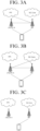
- FIGS. 3A to 3C illustrate exemplary architectures for a wireless communication service.
- a UE is connected in dual connectivity (DC) with an LTE/LTE-A cell and a NR cell.
- DC dual connectivity
- the NR cell is connected with a core network for the legacy fourth-generation mobile communication, that is, Evolved Packet core (EPC).
- EPC Evolved Packet core
- the LTE/LTE-A cell is connected with a core network for 5th generation mobile communication, that is, a 5G core network.
- a service provided by the architecture shown in FIGS. 3A and 3B is referred to as a non-standalone (NSA) service.
- NSA non-standalone
- SA standalone
- the use of a downlink subframe for reception from a base station and an uplink subframe for transmission to the base station may be employed.
- This method may be applicable to both paired spectrums and unpaired spectrums. Paired spectrums involve two subcarriers designated for downlink and uplink operations. For example, one subcarrier within a pair of spectrums may include a pair of a downlink band and an uplink band.
- FIG. 4 illustrates a slot structure of an NR frame.
- a slot in the NR system includes a plurality of symbols in the time domain. For example, in the case of the normal CP, one slot includes seven symbols. On the other hand, in the case of the extended CP, one slot includes six symbols.
- a carrier includes a plurality of subcarriers in the frequency domain.
- a resource block (RB) is defined as a set of consecutive subcarriers (e.g., 12 consecutive subcarriers) in the frequency domain.
- a bandwidth part (BWP) is defined as a sequence of consecutive physical resource blocks (PRBs) in the frequency domain and may be associated with a specific numerology (e.g., SCS, CP length, etc.).
- a terminal may be configured with up to N (e.g., five) BWPs in each of downlink and uplink. Downlink or uplink transmission is performed through an activated BWP. Among the BWPs configured for the terminal, only one BWP may be activated at a given time. In the resource grid, each element is referred to as a resource element (RE), and one complex symbol may be mapped thereto.
- RE resource element
- FIG. 5 shows an example of a subframe type in NR.
- a Transmission Time Interval may be referred to as a subframe or slot.
- the subframe (or slot) may be utilized in a TDD system to minimize data transmission delay.
- a subframe (or slot) includes 14 symbols. The symbol at the head of the subframe (or slot) may be allocated for a DL control channel, and the symbol at the end of the subframe (or slot) may be assigned for a UL control channel. The remaining symbols may be used for either DL data transmission or UL data transmission.
- This subframe (or slot) structure allows sequential downlink and uplink transmissions in one single subframe (or slot). Accordingly, downlink data may be received in a subframe (or slot) and uplink ACK/NACK may be transmitted in the same subframe (or slot).
- Such a subframe (or slot) structure may be referred to as a self-contained subframe (or slot).
- the first N symbols in a slot may be used to transmit a DL control channel and referred to as a DL control region, hereinafter.
- the last M symbols in the slot may be used to transmit a UL control channel and referred to as a UL control region.
- N and M are integers greater than 0.
- a resource region between the DL control region and the UL control region may be used for either DL data transmission or UL data transmission and referred to as a data region.
- a physical downlink control channel (PDCCH) may be transmitted in the DL control region, and a physical downlink shared channel (PDSCH) may be transmitted in the DL data region.
- a physical uplink control channel (PUCCH) may be transmitted in the UL control region, and a physical uplink shared channel (PUSCH) may be transmitted in the UL data region.
- this subframe (or slot) structure reduces the time required for retransmitting data that has failed in reception, thereby minimizing overall data transmission latency.
- a time gap may be required for transitioning between a transmission mode and a reception mode or from the reception mode to the transmission mode.
- a few OFDM symbols when switch from DL to UL in the subframe structure may be configured to a guard period (GP).
- FIG. 6 illustrates a structure of a self-contained slot.
- the frames are structured as a self-contained structure, where one single slot includes a DL control channel, either a DL or UL data channel, and UL control channel.
- a DL control channel either a DL or UL data channel
- UL control channel For example, the first N symbols in a slot may be used for transmitting a DL control channel and referred to as a DL control region.
- the last M symbols in the slot may be used for transmitting an UL control channel and referred to as a UL control region.
- N and M are integers greater than 0.
- a resource region between the DL control region and the UL control region may be used for either DL data transmission or UL data transmission and referred to as a data region.
- the durations are listed in temporal order.
- DL region (i) DL data region, (ii) DL control region + DL data region
- UL region (i) UL data region, (ii) UL data region + UL control region
- a physical downlink control channel may be transmitted in the DL control region, and a physical downlink shared channel (PDSCH) may be transmitted in the DL data region.
- a physical uplink control channel (PUCCH) may be transmitted in the UL control region, and a physical uplink shared channel (PUSCH) may be transmitted in the UL data region.
- DCI Downlink Control Information
- DL data scheduling information for example, DL data scheduling information or UL data scheduling data
- UCI Uplink Control Information
- ACK/NACK Positive Acknowledgement/Negative Acknowledgement
- CSI Channel State Information
- SR Scheduling Request
- a guard period provides a time gap during a process where a gNB and a UE transition from the transmission mode to the reception mode or a process where the gNB and UE transition from the reception mode to the transmission mode.
- the present disclosure is to provide a transmission method and apparatus for controlling periodic uplink transmission in 3GPP NR.
- the disclosure aims to provide a control method and apparatus for enhancing utilization of transmission resources during configured grant (CG)-based transmission to increase the transmission capacity of an extended reality (XR) terminal.
- CG configured grant
- XR extended reality
- 3GPP NR defines CG-based transmission for periodic uplink transmission.
- the CG-based transmission is broadly classified into two primary types: Type 1 and Type 2.
- a transmission resource type In common, a transmission resource type, a modulation and coding scheme (MCS) table, periodic and repeated transmission configuration, etc. are transmitted through a radio resource control (RRC) message/information of 'ConfiguredGrantConfig.
- RRC radio resource control
- Type 1 information indicated by downlink control information (DCI), such as time and frequency resources, and MCS indices, are additionally configured based on the RRC message/information.
- Type 1 and Type 2 are divided according to whether information about transmission performed or not in an actually configured transmission area is transmitted again with the DCI.
- the transmissions based on the CG Type 1 are performed using previously configured time/frequency domains and MCS indices even when there is no activation DCI transmission.
- the transmissions are performed using the activation DCI and the time/frequency domains and MCS indices configured for that DCI and are not performed when there is no corresponding DCI.
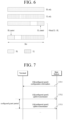
- FIG. 7 illustrates exemplary uplink transmission and reception based on a configured grant (CG).
- CG configured grant
- a base station transmits CG configuration information to a terminal through RRC signaling (S701).
- the CG configuration information transmitted from the base station to the terminal may include period information for performing uplink transmission based on the CG.
- the terminal periodically performs the uplink transmission using the CG based on the period information included in the received CG configuration information (S702 to S703).
- the CG uplink transmission may be repeatedly performed within the CG period. This may be based on information about the number of repetitions included in the CG configuration information.
- the CG-based uplink transmission may correspond to CG transport block transmission.
- control messages for transmitting information about HARQ ACK/NACK for downlink transmission, CSI feedback report, and configured grant-uplink control information (CG-UCI) may be sent as being multiplexed in a CG-PUSCH region.
- the control message for the HARQ ACK/NACK is allocated beginning with the first symbol after the first consecutive DMRS transmission symbol.
- the control message for the CG-UCI is allocated starting from the first symbol after the first consecutive DMRS transmission symbol except the HARQ control message.
- the CSI control message is allocated starting from the first symbol in the PUSCH region that does not transmit the DMRS, except the HARQ control message and the CG-UCI control message.
- the CG-UCI for the CG carries information as follows.
- Specify the enhancements related to capacity - Multiple CG PUSCH transmission occasions in a period of a single CG PUSCH configuration (RAN1, RAN2); - Dynamic indication of unused CG PUSCH occasion(s) based on UCI by the UE (RAN1); - BSR enhancements including at least new BS Table(s); (RAN2); - Delay reporting of buffered data in uplink; (RAN2); - Provision of XR traffic assistance information for DL and UL (e.g. periodicity); (RAN2); - Discard operation of PDU Sets (RAN2); 3.
- the existing NR CG only one transport block is designated per period. Configurations are predetermined based on data volume: a short period with a large transmission area is predefined for periods with a large average data amount, while a long period with a small transmission area is predefined for periods with a small average data amount. Furthermore, the existing NR CG performs the repeated transmission additionally a predefined number of times according to uplink channel environments. However, it struggles to handle a variable average transmission area such as a video stream of XR.
- This proposed method still faces challenges with dynamic reallocation when the previously allocated area is no longer needed. Therefore, another method has been proposed. This method allows a terminal to indicate an area, which parts of the previously allocated areas are not being used for actual transmission, so these areas can be repurposed for other transmission(see the objective 2 in Table 5, "Dynamic indication of unused CG PUSCH occasion(s) based on UCI by the UE (RAN)").
- the disclosure introduces a method and apparatus for configuring the UCI to indicate the transmission of the unused PUSCH information (e.g., the unused transmission occasions of the CG PUSCH) by an actual terminal when multiple CG PUSCH transmissions are set up for CG-based transmission in an NR uplink transmission environment.
- the disclosure introduces a method and apparatus for determining a resource area for the UCI for indicating the unused transmission occasions of the CG PUSCH.
- the UCI for indicating the unused transmission occasions of the PUSCH is referred to as "unused transmission occasion (UTO)-UCI".
- FIG. 8 illustrates exemplary uplink transmission and reception based on a CG according to the disclosure of the present specification.
- uplink transmission (e.g., CG-PUSCH transmission) is performed based on a configured grant period (ConfiguredGrantPeriod).
- the UCI (or CG-UCI) may be transmitted as multiplexed or piggybacked in a resource (or grant) for CG-PUSCH transmission.
- FIG. 8 illustrates five transmission occasions per CG period. Among the five transmission occasions, some transmission occasions may remain unused and not be utilized for transmission. For example, FIG. 8 shows three unused transmission occasions within the first CG period, no unused transmission occasions within the second CG period, four unused transmission occasions within the third CG period, and one unused transmission occasion within the fourth CG.
- the UCI indicating the unused transmission occasion is referred as the UTO-UCI, although it may also be known by other name that convey the same technical meaning.
- the term 'transmission' occasion (TO) may be used interchangeably with 'occasion' to signify the same concept.
- CG period information and information about the number of transmission occasions within the CG period may be included in CG configuration information transmitted to the terminal by the base station.
- the CG configuration information may be transmitted to the terminal through a radio resource control (RRC) message/information.
- RRC radio resource control
- each transmission occasion within one CG period may be subject to repetitive transmissions, based on specified information regarding the number of repetitions.
- the information about the number of repetitions may also be included in the CG configuration information that the base station transmits to the terminal, as described above.
- the disclosure introduces a method of determining a resource location for UTO-UCI transmission. Specifically, methods are provided for determining resource locations (1) when the corresponding UCI is transmitted alone, (2) when the corresponding UCI is indicated to be transmitted together with HARQ or CG-UCI, (3) when the corresponding UCI is indicated to be transmitted together with CSI feedback, and (4) on the second and subsequent occasions.
- the terminal may transmit the UTO-UCI as multiplexed with uplink data through allocated PUSCH transmission resources.
- the resource elements (RE) in the PUSCH transmission resources for the UTO-UCI transmission are determined by methods (to be described later), and the uplink data may be transmitted by rate matching or puncturing/overwriting through the remaining resources except the RE for the UCI transmission.
- the base station may configure or indicate a separate beta offset value for the UTO-UCI transmission.
- the base station may configure (e.g., determine) or indicate whether to perform multiplexing between that UTO-UCI and another UCI.
- the multiplexing different types of UCI refers to the combining the different types of UCI in the form of concatenation in a payload domain. Such a combined payload is transmitted as encoded as one code block, unlike UCI multiplexing within PUSCH transmission resources.
- the multiplexing is configured or indicated refers to that the multiplexing configuration information is transmitted to the terminal by the base station through UE/cell-specific RRC signaling.
- the multiplexing indication information is transmitted to the terminal through medium access control (MAC) control element (CE) signaling or UE-specific/group-common downlink control information (DCI).
- MAC medium access control
- CE control element
- DCI downlink control information
- the base station may explicitly configure or indicate whether to multiplex the UTO-UCI with specific UCI.
- the multiplexing between the UTO-UCI and HARQ-ACK/NACK may be configured (e.g., to be enabled or disabled) by the base station.
- the multiplexing between the UTO-UCI and the CG-UCI may be configured (e.g., to be enabled or disabled) by the base station.
- combination of the multiplexing between the UTO-UCI and the HARQ-ACK/NACK and the multiplexing between the UTO-UCI and the CG-UCI may be configured by the base station.
- the base station may implicitly configure or indicate whether to multiplex the UTO-UCI with specific UCI. For example, whether to perform the multiplexing for the UTO-UCI may be determined based on the existing multiplexing configuration information between CG-UCI and a HARQ. Alternatively, whether to perform the multiplexing for the UTO-UCI may be determined based on combination of multiplexing configuration information between the corresponding CG-UCI and the HARQ, and pieces of UCI transmitted on a PUSCH transmission occasion.
- an indication message for indicating the multiplexing between the HARQ and the CG-UCI may also indicate whether to simultaneously perform the multiplexing for the UTO-UCI.
- the UTO-UCI may always be multiplexed with the HARQ and the CG-UCI.
- t a new message may be introduced that is specifically used for multiplexing a different combination.
- the details are as follows.
- Second embodiment Upon indicating no multiplexing between a HARQ and CG-UCI
- the HARQ, the CG-UCI, and the UTO-UCI may always be individually transmitted regardless of whether an indication message for indicating the multiplexing between the HARQ and the UTO-UCI or an indication message for indicating the multiplexing between the CG-UCI and the UTO-UCI is present or indicated, or the multiplexing between the HARQ and the UTO-UCI or the multiplexing between the CG-UCI and the UTO-UCI may be performed unconditionally.
- the field of the existing 'cg-UCI-Multiplexing' message is expanded so that one message can indicate whether to perform each multiplexing for the HARQ, the CG-UCI and the UTO-UCI.
- the operations based on each indication may be the same as the operations based on the individual messages according to the first disclosure and/or the second disclosure.
- the corresponding message according to the third embodiment may make an indication in an enumerated form excluding a certain combination from the followings:
- '1' (1. HARQ & CG-UCI) is configured as 'disable' and '2' (2. HARQ & UTO-UCI) is configured as 'enable'.
- 'enabled' and 'disabled' may be defined as follows. Here, '0' is configured as 'disabled,' and ⁇ 1' is configured as 'enabled.'
- the first example corresponds to a case that determines whether the HARQ, the CG-UCI, and the UTO-UCI are multiplexed simultaneously or not multiplexed at all. Operations based on two configured as 'enable' in the sixth example may be performed in such a manner that the multiplexing is performed only when two signals are present or the multiplexing is not performed only when only signal pairs configured as 'disable' are present.
- Method 1 refers to a method of determining the resource location when the UTO-UCI is the only UCI to be transmitted on a specific occasion. To this end, the following processes, i.e., operations of the method may be introduced.
- Process 1 of Method 1 Determination of a starting symbol location
- a starting symbol location for allocating the UTO-UCI is determined in a UL-SCH.
- the starting symbol location may be the first symbol in a slot where DM-RS is not allocated, within the entire PUSCH area.
- the starting symbol location may be the first symbol in a slot where the DM-RS is not allocated after the first allocated DM-RS symbol.
- the starting symbol location may be a symbol at a predetermined location specified after the second standards rather than the first standards.
- the location of an resource element (RE) to transmit the UTO-UCI is selected after the starting symbol. To this end, the selection may be performed from the first resource element (RE) among the resource elements (REs) allocated for PUSCH transmission at a transmission point in time. Alternatively, the frequency offsets for a start RE and an end RE may be configured in advance.
- the REs for transmitting the UTO-UCI are consecutively selected in sequence from the corresponding location until enough transmission space is secured to accommodate the length of a UTO-UCI code block, which is predetermined by the UTO-UCI beta offset.
- a new RE location for the transmission may be selected from the first RE as described in the process 2 of method 1, from a configured offset, or by applying an offset or no offset from the second RE according to whether to apply the offset is changed, unlike the first RE.
- Signals not used for the corresponding UTO-UCI transmission are employed for transmitting uplink data.
- Method 2 How to determine a resource location when the UTO-UCI is transmitted together with the HARQ or the CG-UCI
- Method 2 refers to a method of determining the resource location when the UCI to be transmitted on a specific occasion includes the HARQ and the CG-UCI in addition to the UTO-UCI. To this end, the following processes may be introduced. First, on the occasion where the corresponding signal transmission is indicated for the HARQ or the CG-UCI, or both the HARQ and the CG-UCI,
- Method(s) to be described later is related to the simultaneous transmission, and the multiplexing in the following method(s) means that one code block is generated and transmitted using the same error correction code after connection in a messaging stage, unless otherwise specified.
- the process 1 of method 2 is identical to the process 1 of method 1 described above. However, based on the presence of the HARQ, the starting symbol location may be selected differently when the HARQ is absent.
- the location of an resource element (RE) to transmit the UTO-UCI is selected after the starting symbol.
- the selection for the UTO-UCI may be performed from the first RE among the REs allocated for PUSCH transmission at a transmission point in time.
- the selection for the HARQ may be performed from an RE unallocated for the UTO-UCI transmission among the REs allocated for the PUSCH transmission.
- the selection may be performed from the first RE among the REs that are not allocated for the HARQ.
- the REs for transmitting the UTO-UCI are consecutively selected in sequence from the corresponding location until the enough transmission space is secured to accommodate the length of a UTO-UCI code block configured in advance.
- the HARQ and the UTO-UCI may be multiplexed and transmitted simultaneously/together in the same resource space under the conditions that the HARQ and the uplink data have the same priority, the multiplexing is indicated in advance, the message field of the UTO-UCI satisfies a specific bit length condition, or two signals are simply indicated simultaneously. In other words, two messages may be simultaneously encoded by one beta offset as they are connected in the messaging stage.
- the process 3 of method 2 is identical to the process 2 of method 1 previously described.
- the process 4 of method 2 is identical to the process 3 of method 1 described above.
- the HARQ may be allocated avoiding the area allocated to the UTO-UCI or may be overwritten in a previously reserved area.
- the process 5 of method 2 is identical to the process 1 of method 1 described above. However, based on the presence of the CG-UCI, the starting symbol location may be selected differently when the CG-UCI is absent.
- the locations of REs to transmit the UTO-UCI are selected after the starting symbol.
- the selection for the UTO-UCI may be performed from the first RE among the REs allocated for PUSCH transmission at a transmission point in time.
- the selection may be performed from the first RE among the REs not allocated for the CG-UCI.
- the REs for transmitting the UTO-UCI are consecutively selected in sequence from the corresponding location until enough transmission space is secured to accommodate the length of a UTO-UCI code block configured in advance.
- the CG-UCI and the UTO-UCI may be multiplexed and transmitted simultaneously/together in the same resource space under the conditions that the multiplexing is indicated through an RRC message/information in advance, the message field of the UTO-UCI satisfies a specific bit length condition, or two signals are simply indicated simultaneously. In other words, two messages may be simultaneously encoded by being linked together during the messaging stage.
- the beta offset which is not indicated by the DCI or is indicated as semi-static, may be based on the beta offset of the CG-UCI, the bata offset of the UTO-UCI, a higher value between the beta offsets of the CG-UCI and the UTO-UCI, or a separate beta offset value for the multiplexing may be additionally configured.
- the process 7 of method 2 is identical to the process 2 of method 1 described above.
- the process 8 of method 2 is identical to the process 3 of method 1 described above. However, when the CG-UCI has not been multiplexed with the UTO-UCI, the CG-UCI may be allocated before the UL-SCH avoiding the area allocated with the UTO-UCI or may be overwritten in a previously reserved area.
- the process 9 of method 2 is identical to the process 1 of method1 described above. However, based on the presence of the HARQ or the CG-UCI, the starting symbol location may be selected differently when the HARQ or the CG-UCI is absent.
- the locations of REs to transmit the UTO-UCI are selected after the starting symbol.
- the selection for the UTO-UCI may be performed from the first RE among the Res allocated for the UL-SCH at a transmission point in time.
- the selection may be performed from the first RE among the REs allocated for the HARQ.
- the selection may be performed from the first RE among the REs not allocated to the HARQ and the CG-UCI.
- the REs for transmitting the UTO-UCI are consecutively selected in sequence from the corresponding location until enough transmission space is secured to accommodate the length of a UTO-UCI code block configured in advance.
- the HARQ and the HARQ or the UTO-UCI may be multiplexed and transmitted simultaneously/together in the same resource space under the conditions that the HARQ and the uplink data have the same priority, the multiplexing between the HARQ and the UTO-UCI or between the CG-UCI and the UTO-UCI is indicated through the RRC message/information in advance, the message field of the UTO-UCI satisfies a specific bit length condition, or three signals are simply indicated simultaneously. In other words, two or more messages may be simultaneously encoded by being linked together during the messaging stage.
- the process 11 of method 2 is identical to the process 2 of method 1 described above.
- the process 12 of Method 2 is identical to the process 3 of method 1 described above. However, the HARQ or the CG-UCI may be allocated avoiding the area allocated for the UTO-UCI or may be overwritten in a previously reserved area.
- Method 3 How to determine a resource location when it is indicated to transmit the UTO-UCI together with channel state information (CSI) feedback
- Method 3 refers to a method of determining the resource location when the UCI to be transmitted on a specific occasion includes the CSI feedback. To this end, the following processes may be introduced.
- the process of method 3 is identical to the process 1 of method 1 described above. However, based on the presence of the CSI feedback, the starting symbol location may be selected differently when the CSI feedback is absent.
- the location of an RE to transmit the UTO-UCI is selected after the starting symbol.
- the selection for the UTO-UCI may be performed from the first RE among the remaining REs except the REs previously indicated for other purposes than CG at a transmission point in time.
- the selection may be performed from the first RE among the REs not allocated to the CSI.
- the offset of the start RE may be configured in advance.
- the REs for transmitting the UTO-UCI are consecutively selected in sequence from the corresponding location until the transmission space is secured sufficiently.
- Whether to simultaneously transmit these signals may be varied depending on the priority of the HARQ and the configuration of ⁇ UCI-MuxWithDifferentPriority.' If i) the corresponding operation is not configured ii) the priority of the HARQ is low, and iii) the UTO-UCI and the HARQ are multiplexed by the same code, the UTO-UCI and the HARQ may either not be transmitted or may be encoded together, excluding the message corresponding to the HARQ.
- all the UTO-UCI, the HARQ, and the CG-UCI may not be transmitted and may be encoded excluding the message corresponding to the HARQ or excluding the message corresponding to the HARQ and the CG-UCI.
- the process 3 of method 3 is identical to the process 2 of method 1 described above.
- the process 4 of method 3 is identical to the process 3 of method 1 described above.
- the HARQ, the CG-UCI or the CSI feedback may be allocated based on allocation order avoiding the area allocated to the UTO-UCI or may be overwritten in a previously reserved area.
- Method 4 How to determine a resource location on the second and subsequent occasions.
- the occasions may be different in whether to additionally include the HARQ, the CG-UCI, or the CSI feedback.
- the locations thereof may be varied depending on occasions when the foregoing methods are applied thereto.
- the UTO-UCI on the second and subsequent occasions may also be transmitted to the same location as that on the first occasion. This condition may be maintained only when the UTO-UCI is not multiplexed with the HARQ or the CG-UCI.
- the multiplexing may be formed the same even on the second and subsequent occasions, and at this time the previous HARQ or CG-UCI bits may be applied as it is or padded with '0' or ⁇ 1.'
- FIG. 9 is a flowchart for an operation method of a terminal according to an embodiment of the disclosure.
- the terminal configures a physical uplink shared channel (S901).
- the PUSCH refers to a configured grant (CG) PUSCH.
- the terminal configures unused transmission occasion (UTO) - uplink control information (UCI) for indicating an unused transmission occasion of the PUSCH (S902).
- the PUSCH and/or the UTO-UCI configured by the terminal may be based on the configuration information from the base station, and the configuration information from the base station may be CG configuration information (ConfiguredGrantConfig).
- the terminal transmits the UTO-UCI and the HARQ information together to the base station trough the PUSCH (S903).
- the UTO-UCI and the HARQ information may be transmitted together based on a first priority of the HARQ information.
- the uplink data may be transmitted together with the UTO-UCI and the HARQ information.
- the HARQ information and the UTO-UCI may be transmitted by being encoded together.
- the UTO-UCI and the HARQ information may be transmitted together based on a second priority corresponding to at least one transmitted along with the HARQ.
- the UTO-UCI and the HARQ information may be transmitted together based on the priority (i.e., the second priority) of the uplink data and/or the UTO-UCI transmitted along with the HARQ information.
- the UTO-UCI and the HARQ information may be transmitted in consideration of the second priority in addition to the first priority.
- the first priority may be the same as the second priority.
- the UTO-UCI may be sequentially allocated to the resources of the first symbol in a slot where a demodulation-reference signal (DM-RS) is not allocated, within the PUSCH transmission space. If no resources remains in the first symbol, the allocation of the UTO-UCI may continue consecutively to resources of at least one next symbol, also where the DR-RS is not allocated. In addition, the uplink data may be allocated to resources other than those allocated to the DM-RS and the UTO-UCI.
- DM-RS demodulation-reference signal
- the transmission of two or more signals/pieces of information/messages together may indicate that two or more signals/pieces of information/messages are multiplexed and transmitted simultaneously/together to the same resource space. Further, it may also mean that two or more signals/pieces of information/messages are encoded simultaneously/together using one beta offset.
- FIG. 10 is a flowchart for an operation method of a base station according to an embodiment of the disclosure.
- the base station performs configuration for a physical uplink shared channel to the terminal (S1001).
- the PUSCH refers to a configured grant (CG) PUSCH.
- the base station configures unused transmission occasion (UTO)-uplink control information (UCI) for indicating an unused transmission occasion of the PUSCH to the terminal (S1002).
- the PUSCH and/or the UTO-UCI configured by the base station to the terminal may be based on the configuration information from the base station, and the configuration information from the base station may be CG configuration information ConfiguredGrantConfig.
- the base station receives the UTO-UCI and the HARQ information together from the terminal trough the PUSCH (S1003).
- the UTO-UCI and the HARQ information may be received together based on a first priority of the HARQ information.
- the uplink data may be received together with the UTO-UCI and the HARQ information.
- the HARQ information and the UTO-UCI may be received as encoded together.
- the UTO-UCI and the HARQ information may be received together based on a second priority corresponding to at least one received along with the HARQ.
- the UTO-UCI and the HARQ information may be received together based on the priority (i.e., the second priority) of the uplink data and/or the UTO-UCI received along with the HARQ information.
- the UTO-UCI and the HARQ information may be received in consideration of the second priority in addition to the first priority.
- the first priority may be the same as the second priority.
- the UTO-UCI may be sequentially allocated to the resources of the first symbol in a slot where a demodulation-reference signal (DM-RS) has not been allocated, within the PUSCH transmission space. If no resources remain in the first symbol, the allocation may continue consecutively allocated to resources of at least one subsequent symbol, where the DR-RS is not allocated.
- the uplink data may be allocated to resources other than the resources allocated to the DM-RS and the UTO-UCI.
- receiving two or more signals/pieces of information/messages together may mean that two or more signals/pieces of information/messages are multiplexed and transmitted simultaneously/together to the same resource space. Further, it may also mean that two or more signals/pieces of information/messages are encoded simultaneously/together using one beta offset.
- the embodiments may be implemented through various means.
- the embodiments may be implemented by hardware, firmware, software, or a combination thereof. Details will be described with reference to the accompanying drawings.
- FIG. 11 is a block diagram showing apparatuses according to an embodiment of the disclosure.
- a wireless communication system may include a first apparatus 100a and a second apparatus 100b.
- the first apparatus 100a may include a base station, a network node, a transmission terminal, a reception terminal, a wireless apparatus, a radio communication device, a vehicle, a vehicle with an autonomous driving function, a connected car, an unmanned aerial vehicle (UAV), an artificial intelligence (AI) module, a robot, an augmented reality (AR) apparatus, a virtual reality (VR) apparatus, a mixed reality (MR) apparatus, a hologram apparatus, a public safety apparatus, a machine-type communication (MTC) apparatus, an Internet of things (IoT) apparatus, a medial apparatus, a finance technology (FinTech) apparatus (or a financial apparatus), a security apparatus, a climate/environment apparatus, an apparatus related to a 5G service, or other apparatuses related to the fourth industrial revolution.
- UAV unmanned aerial vehicle
- AI artificial intelligence
- AR augmented reality
- VR virtual reality
- MR mixed reality
- hologram apparatus a public safety apparatus
- MTC machine-type communication
- IoT Internet
- the second apparatus 100b may include a base station, a network node, a transmission terminal, a reception terminal, a wireless apparatus, a radio communication device, a vehicle, a vehicle with an autonomous driving function, a connected car, an unmanned aerial vehicle (UAV), an artificial intelligence (AI) module, a robot, an augmented reality (AR) apparatus, a virtual reality (VR) apparatus, a mixed reality (MR) apparatus, a hologram apparatus, a public safety apparatus, a machine-type communication (MTC) apparatus, an Internet of things (IoT) apparatus, a medial apparatus, a finance technology (FinTech) apparatus (or a financial apparatus), a security apparatus, a climate/environment apparatus, an apparatus related to a 5G service, or other apparatuses related to the fourth industrial revolution.
- UAV unmanned aerial vehicle
- AI artificial intelligence
- AR augmented reality
- VR virtual reality
- MR mixed reality
- hologram apparatus a public safety apparatus
- MTC machine-type communication
- IoT Internet
- the first apparatus 100a may include at least one processor such as a processor 1020a, at least one memory such as a memory 1010a, and at least one transceiver such as a transceiver 1031a.
- the processor 1020a may be tasked with executing the previously mentioned functions, procedures, and/or methods.
- the processor 1020a may be capable of implementing one or more protocols. For example, the processor 1020a may perform and manage one or more layers of a radio interface protocol.
- the memory 1010a may be connected to the processor 1020a, and configured to store various types of information and/or instructions.
- the transceiver 1031a may be connected to the processor 1020a, and controlled to transceive radio signals.
- the second apparatus 100b may include at least one processor such as a processor 1020b, at least one memory device such as a memory 1010b, and at least one transceiver such as a transceiver 1031b.
- the processor 1020b may be tasked with executing the previously mentioned functions, procedures, and/or methods.
- the processor 1020b may be capable of implementing one or more protocols.
- the processor 1020b may manage one or more layers of a radio interface protocol.
- the memory 1010b may be connected to the processor 1020b and configured to store various types of information and/or instructions.
- the transceiver 1031b may be connected to the processor 1020b and controlled to transceive radio signaling.
- the memory 1010a and/or the memory 1010b may be respectively connected inside or outside the processor 1020a and/or the processor 1020b and connected to other processors through various technologies such as wired or wireless connection.
- the first apparatus 100a and/or the second apparatus 100b may have one or more antennas.
- an antenna 1036a and/or an antenna 1036b may be configured to transceive a radio signal.
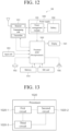
- FIG. 12 is a block diagram showing a terminal according to an embodiment of the disclosure.
- FIG. 12 illustrates the previously described apparatus of FIG. 11 in more detail.
- the apparatus includes a memory 1010, a processor 1020, a transceiving unit 1031 (e.g., transceiving circuit), a power management module 1091 (e.g., power management circuit), a battery 1092, a display 1041, an input unit 1053 (e.g., input circuit), a loudspeaker 1042, a microphone 1052, a subscriber identification module (SIM) card, and one or more antennas.
- a unit is also referred to as a circuit block, a circuit, or a circuit module.
- the processor 1020 may be configured to implement the proposed functions, procedures, and/or methods described in the disclosure.
- the layers of the radio interface protocol may be implemented in the processor 1020.
- the processor 1020 may include an application-specific integrated circuit (ASIC), other chipsets, logic circuits, and/or data processing devices.
- the processor 1020 may be an application processor (AP).
- the processor 1020 may include at least one of a digital signal processor (DSP), a central processing unit (CPU), a graphics processing unit (GPU), and a modulator and demodulator (MODEM).
- DSP digital signal processor
- CPU central processing unit
- GPU graphics processing unit
- MODEM modulator and demodulator
- the processor 1020 may be SNAPDRAGON TM series of processors made by Qualcomm ® , EXYNOS TM series of processors made by Samsung ® , A series of processors made by Apple ® , HELIO TM series of processors made by MediaTek ® , ATOM TM series of processors made by Intel ® , KIRIN TM series of processors made by HiSilicon ® , or the corresponding next-generation processors.
- the power management module 1091 manages a power for the processor 1020 and/or the transceiver 1031.
- the battery 1092 supplies power to the power management module 1091.
- the display 1041 outputs the result processed by the processor 1020.
- the input unit 1053 may be an individual circuit that receives an input from a user or other devices and convey the received input with associated information to the processor 1020. However, the embodiments are not limited thereto.
- the input unit 1053 may be implemented as at least one of touch keys or buttons to be displayed on the display 1041 when the display 1041 is capable of sensing touches, generating related signals according to the sensed touches, and transferring the signals to the processor 1020.
- the SIM card is an integrated circuit used to securely store international mobile subscriber identity (IMSI) used for identifying a subscriber in a mobile telephoning apparatus such as a mobile phone and a computer and the related key. Many types of contact address information may be stored in the SIM card.
- IMSI international mobile subscriber identity
- the memory 1010 is coupled with the processor 1020 in a way to operate and stores various types of information to operate the processor 1020.
- the memory may include read-only memory (ROM), random access memory (RAM), flash memory, a memory card, a storage medium, and/or other storage device.
- ROM read-only memory
- RAM random access memory
- flash memory a memory card
- storage medium a storage medium
- the embodiments described in the disclosure may be implemented as software program or application. In this case, such software program or application may be stored in the memory 1010. In response to a predetermined event, the software program or application stored in the memory 1010 may be fetched and executed by the processor 1020 for performing the function and the method described in this disclosure.
- the memory may be implemented inside of the processor 1020. Alternatively, the memory 1010 may be implemented outside of the processor 1020 and may be connected to the processor 1020 in communicative connection through various means which is well-known in the art.
- the transceiver 1031 is connected to the processor 1020, receives, and transmits a radio signal under control of the processor 1020.
- the transceiver 1031 includes a transmitter and a receiver.
- the transceiver 1031 may include a baseband circuit to process a radio frequency signal.
- the transceiver controls one or more antennas to transmit and/or receive a radio signal.
- the processor 1020 transfers command information to the transceiver 1031 to transmit a radio signal that configures a voice communication data.
- the antenna functions to transmit and receive a radio signal.
- the transceiver 1031 may transfer a signal to be processed by the processor 1020 and transform a signal in baseband. The processed signal may be transformed into audible or readable information output through the speaker 1042.
- the speaker 1042 outputs a sound related result processed by the processor 1020.
- the microphone 1052 receives audio input to be used by the processor 1020.
- a user inputs command information like a phone number by pushing (or touching) a button of the input unit 1053 or a voice activation using the microphone 1052.
- the processor 1020 processes to perform a proper function such as receiving the command information, calling a call number, and the like.
- An operational data on driving may be extracted from the SIM card or the memory 1010.
- the processor 1020 may display the command information or driving information on the display 1041 for a user's recognition or for convenience.
- FIG. 13 is a block diagram of a processor in accordance with an embodiment.
- a processor 1020 may include a plurality of circuitry to implement the proposed functions, procedures and/or methods described herein.
- the processor 1020 may include a first circuit 1020-1, a second circuit 1020-2, and a third circuit 1020-3.
- the processor 1020 may include more circuits. Each circuit may include a plurality of transistors.
- the processor 1020 may be referred to as an application-specific integrated circuit (ASIC) or an application processor (AP) and may include at least one of a digital signal processor (DSP), a central processing unit (CPU), and a graphics processing unit (GPU).
- ASIC application-specific integrated circuit
- AP application processor
- DSP digital signal processor
- CPU central processing unit
- GPU graphics processing unit
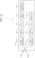
- FIG. 14 is a detailed block diagram of a transceiver of a first apparatus shown in FIG. 11 or a transceiving unit of an apparatus shown in FIG. 12 .
- the transceiving unit 1031 (e.g., transceiving circuit) includes a transmitter 1031-1 and a receiver 1031-2.
- the transmitter 1031-1 includes a discrete Fourier transform (DFT) unit 1031-11 (e.g., DFT circuit), a subcarrier mapper 1031-12 (e.g., subcarrier mapping circuit), an IFFT unit 1031-13 (e.g., IFFT circuit), a cyclic prefix (CP) insertion unit 1031-14 (e.g., CP insertion circuit), and a wireless transmitting unit 1031-15 (e.g., wireless transmitting circuit).
- the transmitter 1031-1 may further include a modulator.
- the transmitter 1031-1 may for example include a scramble unit (e.g., scrambling circuit), a modulation mapper, a layer mapper, and a layer permutator, which may be disposed before the DFT unit 1031-11. That is, to prevent a peak-to-average power ratio (PAPR) from increasing, the transmitter 1031-1 subjects information to the DFT unit 1031-11 before mapping a signal to a subcarrier.
- the signal spread (or pre-coded) by the DFT unit 1031-11 is mapped onto a subcarrier by the subcarrier mapper 1031-12 and made into a signal on the time axis through the IFFT unit 1031-13.
- Some of constituent elements is referred to as a unit in the disclosure. However, the embodiments are not limited thereto. For example, such term "unit” is also referred to as a circuit block, a circuit, or a circuit module.
- the DFT unit 1031-11 performs DFT on input symbols to output complex-valued symbols. For example, when Ntx symbols are input (here, Ntx is a natural number), DFT has a size of Ntx.
- the DFT unit 1031-11 may be referred to as a transform precoder.
- the subcarrier mapper 1031-12 maps the complex-valued symbols onto respective subcarriers in the frequency domain. The complex-valued symbols may be mapped onto resource elements corresponding to resource blocks allocated for data transmission.
- the subcarrier mapper 1031-12 may be referred to as a resource element mapper.
- the IFFT unit 1031-13 performs IFFT on the input symbols to output a baseband signal for data as a signal in the time domain.
- the CP inserting unit 1031-14 copies latter part of the baseband signal for data and inserts the latter part in front of the baseband signal for data.
- CP insertion prevents inter-symbol interference (ISI) and inter-carrier interference (ICI), thereby maintaining orthogonality even in a multipath channel.
- ISI inter-symbol interference
- ICI inter-carrier interference
- the receiver 1031-2 includes a wireless receiving unit 1031-21 (e.g., wireless receiving circuit), a CP removing unit 1031-22 (e.g., CP removing circuit), an FFT unit 1031-23 (e.g., FFT circuit), and an equalizing unit 1031-24 (e.g., equalizing circuit).
- the wireless receiving unit 1031-21, the CP removing unit 1031-22, and the FFT unit 1031-23 of the receiver 1031-2 perform reverse functions of the wireless transmitting unit 1031-15, the CP inserting unit 1031-14, and the IFFT unit 1031-13 of the transmitter 1031-1.
- the receiver 1031-2 may further include a demodulator.
- the unused transmission occasion (UTO)-uplink control information (UCI) for indicating an unused transmission occasion of the physical uplink shared channel (PUSCH), the hybrid automatic repeat and request (HARQ) information, etc. are efficiently transmitted and received through the PUSCH in the wireless communication system.
- Claims of the present disclosure may be combined in various manners. For example, technical features of the method claim of the present disclosure may be combined to implement a device, and technical features of the device claim of the present disclosure may be combined to implement a method. In addition, the technical features of the method claim and the technical features of the device claim of the present disclosure may be combined to implement a device, and technical features of the method claim and the technical features of the device claim of the present disclosure may be combined to implement a method.
Landscapes
- Engineering & Computer Science (AREA)
- Computer Networks & Wireless Communication (AREA)
- Signal Processing (AREA)
- Mobile Radio Communication Systems (AREA)
Applications Claiming Priority (2)
| Application Number | Priority Date | Filing Date | Title |
|---|---|---|---|
| KR20230057011 | 2023-05-02 | ||
| KR1020230185776A KR20240160503A (ko) | 2023-05-02 | 2023-12-19 | 무선 통신 시스템에서 상향링크 전송 방법 및 장치 |
Publications (1)
| Publication Number | Publication Date |
|---|---|
| EP4459914A1 true EP4459914A1 (de) | 2024-11-06 |
Family
ID=90826453
Family Applications (1)
| Application Number | Title | Priority Date | Filing Date |
|---|---|---|---|
| EP24171611.7A Pending EP4459914A1 (de) | 2023-05-02 | 2024-04-22 | Verfahren und vorrichtung zur uplink-übertragung in einem drahtloskommunikationssystem |
Country Status (2)
| Country | Link |
|---|---|
| US (1) | US20240372653A1 (de) |
| EP (1) | EP4459914A1 (de) |
-
2024
- 2024-04-17 US US18/637,834 patent/US20240372653A1/en active Pending
- 2024-04-22 EP EP24171611.7A patent/EP4459914A1/de active Pending
Non-Patent Citations (1)
| Title |
|---|
| YAN CHENG ET AL: "Discussion on CG enhancements for XR capacity", vol. 3GPP RAN 1, no. Online; 20230417 - 20230426, 7 April 2023 (2023-04-07), XP052292925, Retrieved from the Internet <URL:https://www.3gpp.org/ftp/TSG_RAN/WG1_RL1/TSGR1_112b-e/Docs/R1-2302346.zip R1-2302346.docx> [retrieved on 20230407] * |
Also Published As
| Publication number | Publication date |
|---|---|
| US20240372653A1 (en) | 2024-11-07 |
Similar Documents
| Publication | Publication Date | Title |
|---|---|---|
| EP4539579A1 (de) | Verfahren und vorrichtung zur konfiguration eines schlitzformats für vollduplexkommunikation in einem drahtloskommunikationssystem | |
| EP4503806A1 (de) | Rahmenstrukturkonfigurationsverfahren und -vorrichtung für vollduplexkommunikation | |
| KR20240009867A (ko) | 무선 통신 시스템에서 전이중통신(Full Duplex)을 위한 슬롯 포맷 설정 방법 및 장치 | |
| EP4646004A1 (de) | Verfahren und vorrichtung zur bestimmung der rach-gelegenheit in einer subband-vollduplex-kommunikation | |
| EP4646009A1 (de) | Verfahren und vorrichtung zur bestimmung eines rach-ressourcentyps in einer teilband-vollduplex-kommunikation | |
| EP4546699A1 (de) | Verfahren und vorrichtung zur einstellung eines teilbandes für vollduplexkommunikation in einem drahtloskommunikationssystem | |
| EP4486036A1 (de) | Verfahren und vorrichtung zur planung eines datenkanals in einem drahtloskommunikationssystem | |
| EP4642111A1 (de) | Verfahren und vorrichtung zur bestimmung der rach-übertragungsleistung in einer teilband-vollduplex-kommunikation | |
| EP4451780A1 (de) | Verfahren und vorrichtung zur steuerung der uplink-übertragung in einem drahtloskommunikationssystem | |
| EP4459914A1 (de) | Verfahren und vorrichtung zur uplink-übertragung in einem drahtloskommunikationssystem | |
| EP4456645A1 (de) | Verfahren und vorrichtung zur steuerung der uplink-übertragung in einem drahtloskommunikationssystem | |
| EP4648343A1 (de) | Verfahren und vorrichtung zur durchführung von direktzugriff in einer subband-vollduplex-kommunikation | |
| EP4604655A1 (de) | Verfahren und vorrichtung zur durchführung eines direktzugriffsverfahrens in subband-vollduplex | |
| EP4604630A1 (de) | Verfahren und vorrichtung zur steigerung der präambelübertragungsleistung in subband-vollduplex | |
| EP4687365A1 (de) | Verfahren und vorrichtung zur strahlverwaltung für niedrigleistungssignalübertragung und -empfang | |
| EP4629734A1 (de) | Verfahren und vorrichtung zur verwaltung der direktzugriffskanalanpassung für energieeinsparungen | |
| EP4633249A1 (de) | Verfahren und vorrichtung zum senden und empfangen eines signals mit niedriger leistung | |
| EP4443787A1 (de) | Verfahren und vorrichtung zur kanalmessung zur reduzierung von drahtlosleistung | |
| EP4443764A1 (de) | Verfahren und vorrichtung zur meldung von kanalstatusinformationen zur reduzierung von drahtlosleistung | |
| EP4336911A1 (de) | Verfahren und vorrichtung zur signalisierung für netzwerkenergiesparen | |
| EP4598125A1 (de) | Verfahren und vorrichtung zur konfiguration von ltm (l1/l2-ausgelöster mobilität) bei inter-gnb-mobilität | |
| US20250350420A1 (en) | Method and apparatus for full duplex in wireless communication system | |
| KR20240160503A (ko) | 무선 통신 시스템에서 상향링크 전송 방법 및 장치 | |
| KR20240156934A (ko) | 무선 통신 시스템에서 상향링크 전송 제어 방법 및 장치 | |
| KR20240155743A (ko) | 무선 통신 시스템에서 상향링크 전송 제어 방법 및 장치 |
Legal Events
| Date | Code | Title | Description |
|---|---|---|---|
| PUAI | Public reference made under article 153(3) epc to a published international application that has entered the european phase |
Free format text: ORIGINAL CODE: 0009012 |
|
| STAA | Information on the status of an ep patent application or granted ep patent |
Free format text: STATUS: REQUEST FOR EXAMINATION WAS MADE |
|
| 17P | Request for examination filed |
Effective date: 20240422 |
|
| AK | Designated contracting states |
Kind code of ref document: A1 Designated state(s): AL AT BE BG CH CY CZ DE DK EE ES FI FR GB GR HR HU IE IS IT LI LT LU LV MC ME MK MT NL NO PL PT RO RS SE SI SK SM TR |