EP4459913A1 - Übertragungsmodusumschaltverfahren und vorrichtung/speichermedium/vorrichtung - Google Patents
Übertragungsmodusumschaltverfahren und vorrichtung/speichermedium/vorrichtung Download PDFInfo
- Publication number
- EP4459913A1 EP4459913A1 EP21969825.5A EP21969825A EP4459913A1 EP 4459913 A1 EP4459913 A1 EP 4459913A1 EP 21969825 A EP21969825 A EP 21969825A EP 4459913 A1 EP4459913 A1 EP 4459913A1
- Authority
- EP
- European Patent Office
- Prior art keywords
- harq process
- transmission mode
- specific
- transmission
- uplink grant
- Prior art date
- Legal status (The legal status is an assumption and is not a legal conclusion. Google has not performed a legal analysis and makes no representation as to the accuracy of the status listed.)
- Pending
Links
- 230000005540 biological transmission Effects 0.000 title claims abstract description 694
- 238000000034 method Methods 0.000 title claims abstract description 516
- 230000008569 process Effects 0.000 claims abstract description 327
- 238000004891 communication Methods 0.000 claims abstract description 56
- 230000004044 response Effects 0.000 claims abstract description 56
- 230000006870 function Effects 0.000 claims description 40
- 238000004590 computer program Methods 0.000 claims description 24
- 230000015654 memory Effects 0.000 claims description 24
- 238000012545 processing Methods 0.000 claims description 24
- 230000010076 replication Effects 0.000 claims description 17
- 230000003213 activating effect Effects 0.000 claims 3
- FFBHFFJDDLITSX-UHFFFAOYSA-N benzyl N-[2-hydroxy-4-(3-oxomorpholin-4-yl)phenyl]carbamate Chemical compound OC1=C(NC(=O)OCC2=CC=CC=C2)C=CC(=C1)N1CCOCC1=O FFBHFFJDDLITSX-UHFFFAOYSA-N 0.000 description 68
- 230000011664 signaling Effects 0.000 description 9
- 230000008859 change Effects 0.000 description 8
- 238000010586 diagram Methods 0.000 description 8
- 238000005516 engineering process Methods 0.000 description 7
- 239000004065 semiconductor Substances 0.000 description 5
- 238000007726 management method Methods 0.000 description 4
- 230000003287 optical effect Effects 0.000 description 4
- 230000005236 sound signal Effects 0.000 description 4
- 230000004083 survival effect Effects 0.000 description 4
- 229910044991 metal oxide Inorganic materials 0.000 description 3
- 150000004706 metal oxides Chemical class 0.000 description 3
- 229910000577 Silicon-germanium Inorganic materials 0.000 description 2
- 230000009471 action Effects 0.000 description 2
- 230000008901 benefit Effects 0.000 description 2
- 230000001413 cellular effect Effects 0.000 description 2
- 230000000295 complement effect Effects 0.000 description 2
- 230000003993 interaction Effects 0.000 description 2
- 230000000737 periodic effect Effects 0.000 description 2
- JBRZTFJDHDCESZ-UHFFFAOYSA-N AsGa Chemical compound [As]#[Ga] JBRZTFJDHDCESZ-UHFFFAOYSA-N 0.000 description 1
- LEVVHYCKPQWKOP-UHFFFAOYSA-N [Si].[Ge] Chemical compound [Si].[Ge] LEVVHYCKPQWKOP-UHFFFAOYSA-N 0.000 description 1
- 230000001133 acceleration Effects 0.000 description 1
- 230000006978 adaptation Effects 0.000 description 1
- 238000013473 artificial intelligence Methods 0.000 description 1
- 239000003795 chemical substances by application Substances 0.000 description 1
- 238000010276 construction Methods 0.000 description 1
- 238000013500 data storage Methods 0.000 description 1
- 238000013461 design Methods 0.000 description 1
- 230000004069 differentiation Effects 0.000 description 1
- 239000000835 fiber Substances 0.000 description 1
- 238000003384 imaging method Methods 0.000 description 1
- 239000004973 liquid crystal related substance Substances 0.000 description 1
- 230000004048 modification Effects 0.000 description 1
- 238000012986 modification Methods 0.000 description 1
- 230000002093 peripheral effect Effects 0.000 description 1
- 230000008054 signal transmission Effects 0.000 description 1
- 239000007787 solid Substances 0.000 description 1
- 230000003068 static effect Effects 0.000 description 1
Images




Classifications
-
- H—ELECTRICITY
- H04—ELECTRIC COMMUNICATION TECHNIQUE
- H04L—TRANSMISSION OF DIGITAL INFORMATION, e.g. TELEGRAPHIC COMMUNICATION
- H04L1/00—Arrangements for detecting or preventing errors in the information received
- H04L1/12—Arrangements for detecting or preventing errors in the information received by using return channel
- H04L1/16—Arrangements for detecting or preventing errors in the information received by using return channel in which the return channel carries supervisory signals, e.g. repetition request signals
- H04L1/18—Automatic repetition systems, e.g. Van Duuren systems
- H04L1/1822—Automatic repetition systems, e.g. Van Duuren systems involving configuration of automatic repeat request [ARQ] with parallel processes
-
- H—ELECTRICITY
- H04—ELECTRIC COMMUNICATION TECHNIQUE
- H04L—TRANSMISSION OF DIGITAL INFORMATION, e.g. TELEGRAPHIC COMMUNICATION
- H04L1/00—Arrangements for detecting or preventing errors in the information received
- H04L1/12—Arrangements for detecting or preventing errors in the information received by using return channel
- H04L1/16—Arrangements for detecting or preventing errors in the information received by using return channel in which the return channel carries supervisory signals, e.g. repetition request signals
- H04L1/18—Automatic repetition systems, e.g. Van Duuren systems
- H04L1/1812—Hybrid protocols; Hybrid automatic repeat request [HARQ]
-
- H—ELECTRICITY
- H04—ELECTRIC COMMUNICATION TECHNIQUE
- H04L—TRANSMISSION OF DIGITAL INFORMATION, e.g. TELEGRAPHIC COMMUNICATION
- H04L1/00—Arrangements for detecting or preventing errors in the information received
- H04L1/12—Arrangements for detecting or preventing errors in the information received by using return channel
- H04L1/16—Arrangements for detecting or preventing errors in the information received by using return channel in which the return channel carries supervisory signals, e.g. repetition request signals
- H04L1/18—Automatic repetition systems, e.g. Van Duuren systems
- H04L1/1825—Adaptation of specific ARQ protocol parameters according to transmission conditions
-
- H—ELECTRICITY
- H04—ELECTRIC COMMUNICATION TECHNIQUE
- H04L—TRANSMISSION OF DIGITAL INFORMATION, e.g. TELEGRAPHIC COMMUNICATION
- H04L1/00—Arrangements for detecting or preventing errors in the information received
- H04L1/12—Arrangements for detecting or preventing errors in the information received by using return channel
- H04L1/16—Arrangements for detecting or preventing errors in the information received by using return channel in which the return channel carries supervisory signals, e.g. repetition request signals
- H04L1/18—Automatic repetition systems, e.g. Van Duuren systems
- H04L1/1867—Arrangements specially adapted for the transmitter end
- H04L1/1887—Scheduling and prioritising arrangements
-
- H—ELECTRICITY
- H04—ELECTRIC COMMUNICATION TECHNIQUE
- H04L—TRANSMISSION OF DIGITAL INFORMATION, e.g. TELEGRAPHIC COMMUNICATION
- H04L1/00—Arrangements for detecting or preventing errors in the information received
- H04L1/12—Arrangements for detecting or preventing errors in the information received by using return channel
- H04L1/16—Arrangements for detecting or preventing errors in the information received by using return channel in which the return channel carries supervisory signals, e.g. repetition request signals
- H04L1/18—Automatic repetition systems, e.g. Van Duuren systems
- H04L1/1867—Arrangements specially adapted for the transmitter end
- H04L1/189—Transmission or retransmission of more than one copy of a message
-
- H—ELECTRICITY
- H04—ELECTRIC COMMUNICATION TECHNIQUE
- H04L—TRANSMISSION OF DIGITAL INFORMATION, e.g. TELEGRAPHIC COMMUNICATION
- H04L1/00—Arrangements for detecting or preventing errors in the information received
- H04L1/12—Arrangements for detecting or preventing errors in the information received by using return channel
- H04L1/16—Arrangements for detecting or preventing errors in the information received by using return channel in which the return channel carries supervisory signals, e.g. repetition request signals
- H04L1/18—Automatic repetition systems, e.g. Van Duuren systems
- H04L1/1867—Arrangements specially adapted for the transmitter end
- H04L1/1896—ARQ related signaling
-
- H—ELECTRICITY
- H04—ELECTRIC COMMUNICATION TECHNIQUE
- H04W—WIRELESS COMMUNICATION NETWORKS
- H04W28/00—Network traffic management; Network resource management
- H04W28/02—Traffic management, e.g. flow control or congestion control
- H04W28/04—Error control
Definitions
- the disclosure relates to a field of communication technology, and more particularly, to a transmission mode switching method and device, a storage medium, and a device.
- data transmission may have expected arrival time or survival time.
- a data receiver e.g., a user equipment (UE)
- UE user equipment
- the data receiver may request a transmitter (e.g., a network side device) to retransmit the data.
- the receiver may determine that an application service of a current transmission mode is in an unavailable state and may switch the transmission mode.
- the receiver may determine whether to switch the transmission mode according to a number of data transmission failures of hybrid automatic repeat request (HARQ) data in a HARQ process.
- HARQ hybrid automatic repeat request
- the receiver may have multiple HARQ processes, and it is a technical problem to determine the number of data transmission failures of which HARQ process(es) is used for determining whether to switch the transmission mode.
- the disclosure provides a transmission mode switching method and device/ a storage medium/ a device, so as to provide a transmission mode switching method for a user equipment (UE) having multiple hybrid automatic repeat request (HARQ) processes.
- UE user equipment
- HARQ hybrid automatic repeat request
- a transmission mode switching method performed by a UE includes:
- a transmission mode switching method performed by a network side device includes: configuring a first switching condition to a UE, the first switching condition including that a number of transmission failures of a specific HARQ process of the UE is greater than or equal to a first threshold.
- a transmission mode switching device includes:
- a transmission mode switching device includes: a configuring module, configured to configure a first switching condition for a UE, the first switching condition including that a number of transmission failures of a specific HARQ process of the UE is greater than or equal to a first threshold.
- a communication device including a processor and a memory having a computer program stored thereon is provided.
- the computer program is executed by the processor, the device is caused to implement the method of the first aspect of embodiments.
- a communication device including a processor and a memory having a computer program stored thereon is provided.
- the computer program is executed by the processor, the device is caused to implement the method of the second aspect of embodiments.
- a communication device including a processor and a memory having a computer program stored thereon is provided.
- the computer program is executed by the processor, the device is caused to implement the method of the above aspects of embodiments.
- a communication device including a processor and an interface circuit is provided.
- the interface circuit is configured to receive code instructions and transmit them to the processor.
- the processor is configured to run the code instructions to implement the method of the first aspect of embodiments.
- a communication device including a processor and an interface circuit is provided.
- the interface circuit is configured to receive code instructions and transmit them to the processor.
- the processor is configured to run the code instructions to implement the method of the second aspect of embodiments.
- a communication device including a processor and an interface circuit is provided.
- the interface circuit is configured to receive code instructions and transmit them to the processor.
- the processor is configured to run the code instructions to implement the method of the above aspects of embodiments.
- a computer readable storage medium having instructions stored thereon is provided. When the instructions are executed, the method of the first aspect of embodiments is implemented.
- a computer readable storage medium having instructions stored thereon is provided. When the instructions are executed, the method of the second aspect of embodiments is implemented.
- a computer readable storage medium having instructions stored thereon is provided. When the instructions are executed, the method of the above aspects of embodiments is implemented.
- the UE determines the first switching condition including that the number of transmission failures of a specific HARQ process of the UE is greater than or equal to the first threshold.
- the UE counts the number of transmission failures of the specific HARQ process, and in response to the number of transmission failures satisfying the first switching condition, a transmission mode of the UE is switched from the first transmission mode to the second transmission mode.
- the specific HARQ process(es) can be defined in the first switching condition determined by the UE, and the UE may count the number(s) of transmission failures of the specific HARQ process(es) based on the first switching condition to determine whether to switch the transmission mode.
- the specific HARQ process(es) for which the number(s) of transmission failures is to be counted by the UE may be defined.
- the number(s) of data transmission failures of which specific HARQ process(es) is used for determining whether to switch the transmission mode is defined, thus solving the technical problem in the related art of "unable to determine the number(s) of data transmission failures of which specific HARQ process(es) is to be counted to determine whether to switch the transmission mode".
- first, second, and third may be used in embodiments of the disclosure to describe various information, the information should not be limited to these terms. These terms are only used to distinguish the same type of information from each other.
- first information may also be referred to as the second information, and similarly, the second information may also be referred to as the first information.
- second information may also be referred to as the first information.
- the term “if' as used herein can be interpreted as "when", “while” or "in response to determining”.
- a transmission mode switching method, a transmission mode switching device, a user equipment (UE), a network side device and a storage medium provided in embodiments of the disclosure are described in detail below with reference to the accompanying drawings.
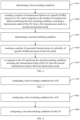
- FIG. 1 is a flowchart of a transmission mode switching method provided by an embodiment of the disclosure. The method is performed by a UE. As illustrated in FIG. 1 , the transmission mode switching method includes the following steps.
- a first switching condition is determined.
- the method can be performed by any UE.
- the UE may be a device that provides voice and/or data connectivity to a user.
- the UE may communicate with one or more core networks via a Radio Access Network (RAN).
- RAN Radio Access Network
- the UE may be an Internet of Things (IoT) UE, such as a sensor device, a cell phone (or a "cellular" phone), and a computer with an IoT UE.
- the UE may also be a stationary, portable, pocket-sized, handheld, computer-built, or vehicle-mounted device, such as, a Station (STA), a subscriber unit, a subscriber station, a mobile station, a mobile, a remote station, an access point, a remote terminal, an access terminal, a user terminal, or a user agent.
- STA Station
- the UE may be an unmanned aerial vehicle device.
- the UE may be an in-vehicle device, for example, an electronic control unit (ECU) having a wireless communication function, or a wireless terminal external to the ECU.
- the UE can also be a roadside device, for example, a street light, a signal light, or other roadside devices having the wireless communication function.
- the first switching condition may include that a number of transmission failures of a specific hybrid automatic repeat request (HARQ) process of the UE is greater than or equal to a first threshold.
- the first threshold may be pre-set, and the first threshold may be greater than or equal to 1.
- the first threshold may be 1.
- the above-mentioned specific HARQ process may include one or more HARQ processes among all HARQ processes currently performed by the UE.
- the specific HARQ process may be a HARQ process for subsequently counting the number of transmission failures.
- the specific HARQ process described above may include at least one of the following types.
- the first type is a HARQ process specified by a network side device or agreed upon by a protocol.
- the network side device may specify the HARQ process-1 of the UE as the specific HARQ process.
- the second type is a HARQ process corresponding to at least one configured uplink grant configuration specified by a network side device or agreed upon by a protocol.
- the network side device configures two Configured (uplink) Grant (CG) configurations for a logical channel of the UE, namely, a CG-1 configuration and a CG-2 configuration
- the CG-1 configuration corresponds to a HARQ process-1 and a HARQ process-2
- the CG-2 configuration corresponds to a HARQ process-3 and a HARQ process-4
- the network side device may specify the HARQ processes corresponding to the CG-1 configuration and the CG-2 configuration, i.e., the HARQ process-1, the HARQ process-2, the HARQ process-3 and the HARQ process-4, as the specific HARQ processes.
- the third type is a HARQ process corresponding to data that corresponds to a specific identifier (i.e., a HARQ process for transmitting the data corresponding to the specific identifier).
- the above specific identifier may be assigned by the network side device. In another embodiment of the disclosure, the above specific identifier may be agreed upon by a protocol. In an embodiment of the disclosure, the above specific identifier may include at least one of the following:
- determining the first switching condition includes at least one of the following:
- the UE can determine, based on the protocol and/or the indication of the network side device, the specific HARQ process for which the number of transmission failures is to be counted subsequently. Whether the UE switches the transmission mode can be determined directly based on a counting result of the number of transmission failures of the specific HARQ process and the first switching condition. That is, embodiments of the disclosure specify the number(s) of data transmission failures of which specific HARQ process(es) is used for determining whether to switch the transmission mode, which solves the technical problem in the related art of "unable to determine the number(s) of data transmission failures of which specific HARQ process(es) is to be counted to determine whether to switch the transmission mode".
- the number of transmission failures of the specific HARQ process of the UE is counted, and in response to the number of transmission failures satisfying the first switching condition, a transmission mode of the UE is switched from a first transmission mode to a second transmission mode.
- the UE may only count the number of transmission failures for the specific HARQ process without having to count the number of transmission failures for other HARQ processes.
- all the HARQ processes currently performed by the UE include a HARQ process-1, a HARQ process-2, a HARQ process-3 and a HARQ process-4, and the specific HARQ processes are the HARQ process-1 and the HARQ process-2, the UE may only count the numbers of transmission failures of the HARQ process-1 and the HARQ process-2, and does not need to count the numbers of transmission failures of the HARQ process-3 and the HARQ process-4.
- the UE may count the number of transmission failures of each specific HARQ process independently. In another embodiment of the disclosure, if the UE has a plurality of specific HARQ processes, the UE may count the number of transmission failures corresponding to the plurality of specific HARQ processes jointly, and details about this part can be referred to the following description of embodiments.
- the aforementioned number of transmission failures may be a number of consecutive failures.
- the number of consecutive failures of the specific HARQ process is greater than or equal to the first threshold, it is determined that the number of transmission failures of the UE satisfies the first switching condition.
- the counted number of transmission failures satisfies the first switching condition, it means that multiple transmission failures have already occurred under the first transmission mode and an application service of the first transmission mode may be in an unavailable state.
- the first transmission mode is still used for data transmission, data transmission may still be failed, and thus the transmission mode of the UE may be switched from the first transmission mode to the second transmission mode.
- a data replication function of the second transmission mode is greater than a data replication function of the first transmission mode. That is, a probability of successful data transmission in the second transmission mode is greater than a probability of successful data transmission in the first transmission mode.
- switching the transmission mode of the UE from the first transmission mode to the second transmission mode may include at least one of the following methods.
- the first method is to activate a data replication function of a specific bearer.
- the above-mentioned specific bearer may be a bearer currently used by the UE to transmit data.
- the bearer may be a DRB and/or a Signaling Radio Bearer (SRB).
- the data replication function may be a Packet Data Convergence Protocol (PDCP) data replication function.
- PDCP Packet Data Convergence Protocol
- the UE can keep the data replication function of the specific bearer in the activated state. If the data replication function of the specific bearer is currently in a deactivated state, when the UE switches the transmission mode from the first transmission mode to the second transmission mode based on the first method, the UE can activate part of or all the radio link control (RLC) entities associated with the specific bearer. As a result, the PDCP entity of the UE can replicate the transmitted data and send the replicated data to each activated RLC entity respectively, and then the data is transmitted to the base station.
- RLC radio link control
- which RLC entities associated with the specific bearer are activated when using the first method to switch the transmission mode, which RLC entities associated with the specific bearer are activated can be determined based on an indication from the network side device. In another embodiment of the disclosure, when using the first method to switch the transmission mode, which RLC entities associated with the specific bearer are activated can be determined based on an agreement of a protocol.
- the specific bearer is a DRB-1
- the UE may determine to activate all the RLC entities of the DRB-1 based on an agreement of a protocol when the first method is used to switch the transmission mode.
- the second method is to change a number of RLC entities in an activated state corresponding to a specific bearer.
- changing the number of RLC entities in the activated state corresponding to the specific bearer may be: increasing the number of RLC entities in the activated state corresponding to the specific bearer.
- the increased number of activated RLC entities may be determined based on an agreement of a protocol and/or an indication from a network side device.
- the specific bearer is the DRB-1
- the number of PDCP-associated RLC entities of the DRB-1 is 4, and the number of activated RLC entities of the DRB-1 under the first transmission mode is 2. If it is determined that the UE satisfies the above mentioned first switching condition and intends to switch the transmission mode of the UE from the first transmission mode to the second transmission mode, the UE can switch the transmission mode to the second transmission mode by adding 1 activated RLC entity (i.e., making the total number of activated RLC entities of DRB-1 to be 3).
- changing the number of RLC entities in the activated state corresponding to the specific bearer may be that the UE determines a specified number based on at least one of an indication from a network side device, an agreement of a protocol, or an autonomous determination by the UE itself.
- the terminal increases the number of activated RLC entities to the specified number.
- the UE maintains the number of currently activated RLC entities. If the number of RLC entities in the activated state corresponding to the specific bearer under the first transmission mode is greater than the specified number, the UE maintains the number of currently activated RLC entities or reduces the number of activated RLC entities to the specified number.
- the specific bearer is the DRB-1
- the number of RLC entities associated with the DRB-1 is 4, namely, a RLC-1, a RLC-2, a RLC-3, and a RLC-4, and the specified number is 3.
- the number of activated RLC entities is 2, i.e., the RLC-1 and the RLC-2.
- the UE may increase the number of activated RLC entities to 3. That is, the UE may activate another RLC entity other than the RLC-1 and the RLC-2, such as a RLC-3.
- the number of activated RLC entities is 3, namely, the RLC-1, the RLC-2 and the RLC-3.
- the UE may maintain the number of currently activated RLC entities.
- the number of activated RLC entities is 4, namely, the RLC-1, the RLC-2, the RLC-3 and a RLC-4.
- the UE may maintain the number of currently activated RLC entities or reduce the number of activated RLC entities to the specified number of 3. For example, the UE may activate only the RLC-1, the RLC-2 and the RLC-3.
- the third method is to activate a designated first RLC entity.
- the first RCL entity may include at least one RLC entity. In an embodiment of the disclosure, the first RLC entity may be determined based on an indication from a network side device. In another embodiment of the disclosure, the first RLC entity may be determined based on an agreement of a protocol.
- the transmission mode of the UE when the transmission mode of the UE is switched from the first transmission mode to the second transmission mode based on the third method, if the RLC entity activated under the first transmission mode is the same as the first RLC entity, the currently activated RLC entity is kept unchanged, and if the RLC entity activated under the first transmission mode is different from the first RLC entity, it is changed to activate the first RLC entity.
- the specific bearer is the DRB-1
- the number of RLC entities associated with the DRB-1 is 4, namely, the RLC-1, the RLC-2, the RLC-3 and the RLC-4
- the first RLC entities are the RLC-1, the RLC-2 and the RLC-3.
- the activated RLC entities are the RLC-1, the RLC-2 and the RLC-4.
- the fourth method is to change a type of an available uplink grant configuration of a specific logical channel of a specific bearer.
- changing the type of the available uplink grant configuration of the specific logical channel of the specific bearer may include the following methods.
- Method a is to determine that a subcarrier spacing (SCS) of an uplink grant configuration available to the second transmission mode includes all types of SCS.
- SCS subcarrier spacing
- the UE when switching the transmission mode from the first transmission mode to the second transmission mode using the above mentioned method a, the UE can make all types of SCS of uplink grant configuration to be available to the specific logical channel LCH-1 of the specific bearer DRB-1.
- Method b is to determine that a SCS of an uplink grant configuration available to the second transmission mode includes an SCS whose value is greater than an SCS value used by the first transmission mode.
- Method c is to determine that a duration of a physical uplink shared channel (PUSCH) corresponding to an uplink grant configuration available to the second transmission mode includes all PUSCH durations.
- PUSCH physical uplink shared channel
- an available uplink grant configuration of the specific logical channel LCH-1 of the specific bearer DRB-1 under the first transmission mode is an uplink grant configuration in which a duration of the PUSCH is less than or equal to 7 Orthogonal Frequency Division Multiplexing (OFDM) symbols
- the UE when adopting the above-described method c to switch the transmission mode from the first transmission mode to the second transmission mode, the UE can make uplink grant configurations of all PUSCH durations to be available to the specific logical channel LCH-1 of the specific bearer DRB-1.
- OFDM Orthogonal Frequency Division Multiplexing
- Method d is to determine that the second transmission mode is capable to use an uplink grant configuration type-1 (Configured Grant Type-1).
- the UE when switching the transmission mode from the first transmission mode to the second transmission mode adopting the above mentioned method d, the UE can make the Configured uplink Grant Type-1 to be available to the specific logical channel LCH-1 of the specific bearer DRB-1.
- Method e is to determine that the second transmission mode is capable to use uplink grant configurations of all cells.
- the UE when switching the transmission mode from the first transmission mode to the second transmission mode using the above mentioned method e, the UE can make the uplink grant configurations of all cells to be available to the specific logical channel LCH-1 of the specific bearer DRB-1.
- Method f is to determine that the second transmission mode is capable to use an uplink grant configuration of a designated cell.
- the designated cell may be determined based on a protocol agreement. In another embodiment of the disclosure, the designated cell may be determined based on an indication from a network side device.
- the designated cell may be a cell-x (e.g., a Primary cell (PCell) or a Primary Secondary cell (PSCell)), with x being a positive integer.
- PCell Primary cell
- PSCell Primary Secondary cell
- the designated cell is a cell-2. If the uplink grant configuration available to the specific logical channel LCH-1 of the specific bearer DRB-1 under the first transmission mode is an uplink grant configuration of a cell-1, when switching the transmission mode from the first transmission mode to the second transmission mode using the above mentioned method f, the UE can make an uplink grant configuration of the cell-2 to be available to the specific logical channel LCH-1 of the specific bearer DRB-1.
- Method g is to determine that the second transmission mode is capable to use all resources of an uplink grant configuration type-2 (Configured Grant Type-2).
- the network side device configures multiple sets of resources of the Configured uplink Grant Type-2 for the UE, namely, Configured uplink Grant Type-2 resource-1 and Configured uplink Grant Type-2 resource-2. If the uplink grant configuration available to the specific logical channel LCH-1 of the specific bearer DRB-1 under the first transmission mode is the Configured uplink Grant Type-2 resource-1, when the UE adopts the above method g to switch the transmission mode from the first transmission mode to the second transmission mode, the UE may make all the resources of the uplink grant configuration type-2 to be available to the specific logical channel LCH-1 of the specific bearer DRB-1. That is, the Configured uplink Grant Type-2 resource-1 and the Configured uplink Grant Type-2 resource-2 can be used.
- Method h is to determine that the second transmission mode is capable to use uplink grant configurations of all physical priorities.
- the uplink grant configuration available to the specific logical channel LCH-1 of the specific bearer DRB-1 under the first transmission mode is an uplink grant configuration of physical priority-1
- the UE when the UE adopts the above mentioned method h to switch the transmission mode from the first transmission mode to the second transmission mode, the UE can make the uplink grant configurations of all physical priorities to be available to the specific logical channel LCH-1 of the specific bearer DRB-1.
- the UE when the UE counts the number of transmission failures of the specific HARQ process and determines that the number of transmission failures of the specific HARQ process satisfies the first switching condition, it can switch the transmission mode from the first transmission mode to the second transmission mode by executing any of the above-described first method to the fourth method.
- the UE determines the first switching condition including that the number of transmission failures of a specific HARQ process of the UE is greater than or equal to the first threshold.
- the UE counts the number of transmission failures of the specific HARQ process, and in response to the number of transmission failures satisfying the first switching condition, a transmission mode of the UE is switched from the first transmission mode to the second transmission mode.
- the specific HARQ process(es) can be defined in the first switching condition determined by the UE, and the UE may count the number(s) of transmission failures of the specific HARQ process(es) based on the first switching condition to determine whether to switch the transmission mode.
- the specific HARQ process(es) for which the number(s) of transmission failures is to be counted by the UE may be defined. Therefore, for a UE having multiple HARQ processes, the number(s) of data transmission failures of which specific HARQ process(es) is used for determining whether to switch the transmission mode is defined, thus solving the technical problem in the related art of "unable to determine the number(s) of data transmission failures of which specific HARQ process(es) is to be counted to determine whether to switch the transmission mode". Therefore, the UE and the network side device have a consistent understanding of the condition for entering a survival time state (i.e., switching to the second transmission mode).
- FIG. 2 is a flowchart of a transmission mode switching method provided by an embodiment of the disclosure. The method is performed by a UE. As illustrated in FIG. 2 , the transmission mode switching method includes the following steps.
- a first switching condition is determined.
- step 201 For the relevant introduction of step 201, reference can be made to the descriptions of the above embodiments, which will not be repeated here in embodiments of the disclosure.
- a number of transmission failures of each specific HARQ process of the UE is counted independently, and in response to the number of transmission failures satisfying the first switching condition, a transmission mode of the UE is switched from a first transmission mode to a second transmission mode.
- counting the number of transmission failures of each specific HARQ process of the UE independently may include that each specific HARQ process corresponds to a counter for counting the number of transmission failures.
- the number of the counter for counting the number of transmission failures corresponding to the certain specific HARQ process is increased by one.
- the specific HARQ processes are a HARQ process-1 and a HARQ process-2, and the HARQ process-1 and the HARQ process 2 each corresponds to one counter.
- the number of the counter for counting the number of transmission failures corresponding to the HARQ process-1 is increased by one, and in response to an occurrence of a data transmission failure of the HARQ process-2, the number of the counter for counting the number of transmission failures corresponding to the HARQ process-2 is increased by one.
- a method for determining the number of transmission failures of the specific HARQ process of the UE includes at least one of the following:
- the data retransmission indication or the data reception failure indication described above may be sent to the UE by the network side device via a Downlink Control Information (DCI) signaling.
- DCI Downlink Control Information
- counting the number of transmission failures of each specific HARQ process independently may include counting the number of transmission failures of each specific HARQ process starting from the first transmission of new data for each specific HARQ process.
- counting starts from the first transmission of the data 1 for the specific HARQ process-1.
- the number of the counter for counting the number of transmission failures corresponding to the specific HARQ process-1 is increased by 1. If the specific HARQ process-1 starts to transmit data 2, the number of the counter for counting the number of transmission failures corresponding to the specific HARQ process-1 is set to an initial value, which may be 0.
- counting the number of transmission failures of each specific HARQ process independently may include counting the number of transmission failures of each specific HARQ process starting from the first transmission of new data for each specific HARQ process over a configured uplink grant configuration.
- the HARQ process includes a HARQ process transmitted on a configured uplink grant configuration, and/or, a HARQ process transmitted on a dynamically scheduled uplink grant configuration.
- the configured uplink grant (CG) configuration described above is configured by the network side device to the UE, and the type of the CG configuration is periodic. There may be multiple CG configurations configured by the network side device to the UE. The network side device can select one or more CG configurations from the multiple CG configurations for the UE to use.
- the dynamically scheduled (dynamic grant, DG) uplink grant configuration is also configured by the network side device to the UE, and is dynamically scheduled based on a signaling (e.g., a DCI signaling).
- counting the number of transmission failures of each specific HARQ process starting from the first transmission of new data for each specific HARQ process on the CG configuration may include the following method.
- the network side device configures the UE with a CG configuration, i.e., a CG-1 configuration, and a specific HARQ process-1 can use the CG-1 configuration to transmit data.
- a specific HARQ process-1 can use the dynamically scheduled uplink grant configuration to transmit data.
- it may be started from the first transmission of new data for the HARQ process-1 on the CG-1 configuration.
- counting the number of transmission failures of each specific HARQ process independently may include counting the number of transmission failures of each specific HARQ process starting from the first transmission of new data for each specific HARQ process on a dynamically scheduled uplink grant configuration.
- the UE determines the first switching condition including that the number of transmission failures of a specific HARQ process of the UE is greater than or equal to the first threshold.
- the UE counts the number of transmission failures of the specific HARQ process, and in response to the number of transmission failures satisfying the first switching condition, a transmission mode of the UE is switched from the first transmission mode to the second transmission mode.
- the specific HARQ process(es) can be defined in the first switching condition determined by the UE, and the UE may count the number(s) of transmission failures of the specific HARQ process(es) based on the first switching condition to determine whether to switch the transmission mode.
- the specific HARQ process(es) for which the number(s) of transmission failures is to be counted by the UE may be defined. Therefore, for a UE having multiple HARQ processes, the number(s) of data transmission failures of which specific HARQ process(es) is used for determining whether to switch the transmission mode is defined, thus solving the technical problem in the related art of "unable to determine the number(s) of data transmission failures of which specific HARQ process(es) is to be counted to determine whether to switch the transmission mode".
- FIG. 3 is a flowchart of a transmission mode switching method provided by an embodiment of the disclosure. The method is performed by a UE. As illustrated in FIG. 3 , the transmission mode switching method includes the following steps.
- a first switching condition is determined.
- step 301 A related description of step 301 can be referred to the above description of embodiments, which will not be repeated herein.
- a number of transmission failures of a plurality of specific HARQ processes is counted jointly, and in response to the number of transmission failures satisfying the first switching condition, a transmission mode of the UE is switched from a first transmission mode to a second transmission mode.
- counting the number of transmission failures of the plurality of specific HARQ processes of the UE jointly may be as follows.
- the plurality of specific HARQ processes correspond to one counter for counting the number of transmission failures, and in response to an occurrence of a data transmission failure of any specific HARQ process, the number of the counter for counting the number of transmission failures is increased by 1.
- the specific HARQ processes are a HARQ process-1 and a HARQ process-2, and the HARQ process-1 and the HARQ process-2 correspond to one counter.
- the number of the counter is increased by 1.
- a method for determining the number of transmission failures includes at least one of the following:
- the above data retransmission indication and the data reception failure indication may be sent by the network side device to the UE via a DCI signaling.
- the number of transmission failures of the plurality of specific HARQ processes is counted starting from the first transmission of new data for a specific HARQ process firstly occurring in the plurality of specific HARQ processes.
- the number of transmission failures of the data 1 for the specific HARQ process-1 and the specific HARQ process-2 is to be counted, and the specific HARQ process-1 occurs before the specific HARQ process-2.
- the counting may start from the first transmission of the data 1 for the specific HARQ process-1.
- the number of the counter for counting the number of transmission failures is increased by 1.
- the number of transmission failures of each specific HARQ process may be counted starting from the first transmission of new data over a configured uplink grant configuration for the specific HARQ process first occurring in the plurality of specific HARQ processes.
- the number of transmission failures of the data 1 for the specific HARQ process-1 and the specific HARQ process-2 may be counted, and the specific HARQ process-1 occurs before the specific HARQ process-2.
- the network side device configures a configured uplink grant configuration for the UE, i.e., a CG-1 configuration.
- the specific HARQ process-1 can use the CG-1 configuration to transmit data.
- the specific HARQ process-1 can use the dynamically scheduled uplink grant configuration to transmit data.
- counting may be started from the first transmission of the new data in the HARQ process-1 on the CG-1 configuration.
- counting the number of transmission failures of each specific HARQ process may be started from the first transmission of the new data for the specific HARQ process first occurring in the plurality of specific HARQ processes on the dynamically scheduled uplink grant configuration.
- the UE determines the first switching condition including that the number of transmission failures of a specific HARQ process of the UE is greater than or equal to the first threshold.
- the UE counts the number of transmission failures of the specific HARQ process, and in response to the number of transmission failures satisfying the first switching condition, a transmission mode of the UE is switched from the first transmission mode to the second transmission mode.
- the specific HARQ process(es) can be defined in the first switching condition determined by the UE, and the UE may count the number(s) of transmission failures of the specific HARQ process(es) based on the first switching condition to determine whether to switch the transmission mode.
- the specific HARQ process(es) for which the number(s) of transmission failures is to be counted by the UE may be defined. Therefore, for a UE having multiple HARQ processes, the number(s) of data transmission failures of which specific HARQ process(es) is used for determining whether to switch the transmission mode is defined, which solves the technical problem in the related art of "unable to determine the number(s) of data transmission failures of which specific HARQ process(es) is to be counted to determine whether to switch the transmission mode".
- FIG. 4 is a flowchart of a transmission mode switching method provided by an embodiment of the disclosure. The method is performed by a UE. As illustrated in FIG. 4 , the transmission mode switching method includes the following steps.
- a first switching condition is determined.
- a number of transmission failures of a specific HARQ process is counted, and in response to the number of transmission failures satisfying the first switching condition, a transmission mode of the UE is switched from a first transmission mode to a second transmission mode.
- steps 401-402 can be described with reference to the above description of embodiments, which will not be repeated herein.
- a second switching condition is determined.
- the transmission mode of the UE after the transmission mode of the UE is switched from the first transmission mode to the second transmission mode at step 402, the transmission mode may be switched back to the first transmission mode from the second transmission mode in subsequent processes.
- a second switching condition is set, and the second switching condition is a condition for instructing the UE to switch the transmission mode back to the first transmission mode from the second transmission mode.
- the second switching condition may include at least one of the following:
- the switching indication information includes at least one of the following:
- the second switching condition may be determined based on an indication form a network side device. In another embodiment of the disclosure, the second switching condition may be determined based on a protocol agreement.
- the second switching condition when the second switching condition is receiving the switching indication information sent by the network side device, the second switching condition may be determined based on the indication of the network side device.
- the second switching condition when the second switching condition is that the number of successful transmissions of a specific HARQ process of the UE is greater than or equal to the second threshold, the second switching condition may be determined based on the indication of the network side device, and/or, based on a protocol agreement.
- a number of successful transmissions of the specific HARQ process of the UE is counted.
- the UE may only count the number of successful transmissions of the specific HARQ process and does not need to count the number of successful transmissions of other HARQ processes.
- all HARQ processes currently being performed by the UE include a HARQ process-1, a HARQ process-2, a HARQ process-3 and a HARQ process-4, and the specific HARQ processes are the HARQ process-1 and the HARQ process-2.
- the UE may only count the number of successful transmissions of the HARQ process-1 and the HARQ process-2, and does not need to count the number of successful transmissions of the HARQ process-3 and the HARQ process-4.
- the UE when the UE has a plurality of specific HARQ processes, the UE may independently count the number of successful transmissions of each specific HARQ process. In another embodiment of the disclosure, when the UE has a plurality of specific HARQ processes, the UE may jointly count the number of successful transmissions of the plurality of specific HARQ processes.
- the detailed description of this section can be referred to the following description of embodiments.
- the transmission mode of the UE is switched from the second transmission mode to the first transmission mode.
- the above second switching condition is that the number of successful transmissions of the specific HARQ process of the UE is greater than or equal to the second threshold
- the above number of successful transmissions may refer to the number of consecutive successful transmissions.
- the UE transmits new data for a (greater than the second threshold) times consecutively through the specific HARQ process-1 using the resource of the CG-1 configuration, during which no data transmission failure indication (or, data retransmission indication) is received, it is determined that the number of successful transmissions of the specific HARQ process of the UE satisfies the second preset condition.
- the above second switching condition is receiving the indication sent by the network side device, when the UE receives the indication sent by the network side device, it is determined that the UE satisfies the second switching condition.
- the above-described method of switching the transmission mode of the UE from the second transmission mode to the first transmission mode may include at least one of the following methods.
- the specific bearer described above may be a bearer currently used by the UE to transmit data, which may be a DRB and/or an SRB.
- the data replication function described above may be a PDCP data replication function.
- the PDCP data replication function of the specific bearer DRB-1 under the second transmission mode is currently in an activated state
- the PDCP data replication function of the DRB 1 may be de-activated when the UE satisfies the second switching condition and method 1 is used to switch the transmission mode of the UE from the second transmission mode to the first transmission mode.
- the number of RLC entities associated with the PDCP of the specific bearer DRB-1 is 4, and the number of activated RLC entities of the specific bearer DRB-1 under the second transmission mode is 3.
- the UE may reduce the number of activated RLC entities by 1 (i.e., the total number of activated RLC entities of the specific bearer DRB-1 is reduced to 2).
- a specified second RLC entity is activated.
- the second RCL entity may include at least one RLC entity.
- the second RLC entity may be determined based on an indication of a network side device.
- the second RLC entity may be determined based on a protocol agreement.
- the number of RLC entities associated with the PDCP of the specific bearer DRB-1 is 4, namely, a RLC entity-1, a RLC entity-2, a RLC entity-3 and a RLC entity-4, and the second RLC entity is the RLC entity-1. If the activated RLC entities are the RLC entity-1, the RLC entity-2, and the RLC entity-3 under the second transmission condition, when the UE satisfies the second switching condition and the method 3 is used to switch the transmission mode of the UE from the second transmission mode to the first transmission mode, only RLC entity-1 may be activated.
- a type of an available uplink grant configuration of a specific logical channel of a specific bearer is changed.
- the type of the available uplink grant configuration of the specific logical channel of the specific bearer may be changed to: a type of uplink grant configuration specified by the network side device.
- the specified type of uplink grant configuration may be, for example, a type of uplink grant configuration specified by RRC configuration.
- the transmission mode of the UE is switched from the second transmission mode to the first transmission mode by executing any of the above-described methods 1 to 4.
- the above step 404 is an optional step.
- the second switching condition determined at step 403 may not need to be performed. If the second switching condition determined at step 403 includes that "the number of successful transmissions of the specific HARQ process of the UE is greater than or equal to the second threshold", the above step 403 needs to be performed.
- the UE determines the first switching condition including that the number of transmission failures of a specific HARQ process of the UE is greater than or equal to the first threshold.
- the UE counts the number of transmission failures of the specific HARQ process, and in response to the number of transmission failures satisfying the first switching condition, a transmission mode of the UE is switched from the first transmission mode to the second transmission mode.
- the specific HARQ process(es) can be defined in the first switching condition determined by the UE, and the UE may count the number(s) of transmission failures of the specific HARQ process(es) based on the first switching condition to determine whether to switch the transmission mode.
- the specific HARQ process(es) for which the number(s) of transmission failures is to be counted by the UE may be defined. Therefore, for a UE having multiple HARQ processes, the number(s) of data transmission failures of which specific HARQ process(es) is used for determining whether to switch the transmission mode is defined, which solves the technical problem in the related art of "unable to determine the number(s) of data transmission failures of which specific HARQ process(es) is to be counted to determine whether to switch the transmission mode".
- FIG. 5 is a flowchart of a transmission mode switching method provided by an embodiment of the disclosure. The method is performed by a UE. As illustrated in FIG. 5 , the transmission mode switching method includes the following steps.
- a first switching condition is determined.
- a number of transmission failures of a specific HARQ process is counted, and in response to the number of transmission failures satisfying the first switching condition, a transmission mode of the UE is switched from a first transmission mode to a second transmission mode.
- a second switching condition is determined.
- steps 501-502 can be described with reference to the above description of embodiments, which will not be repeated herein.
- a number of successful transmissions of each specific HARQ process of the UE is counted independently.
- counting the number of successful transmissions of each specific HARQ process of the UE independently may include that each specific HARQ process corresponds to a counter for counting the number of successful transmissions.
- the number of the counter for counting the number of successful transmissions corresponding to the specific HARQ process is increased by 1.
- the specific HARQ processes are a HARQ process-1 and a HARQ process-2, and the HARQ process-1 and the HARQ process-2 each corresponds to one counter.
- the counter for counting the number of successful transmissions corresponding to the HARQ process-1 is increased by 1
- the counter for counting the number of successful transmissions corresponding to the HARQ process-2 is increased by 1.
- a method for determining the number of successful transmissions includes at least one of the following:
- the above data new-transmission indication and the data reception success indication may be sent by the network side device to the UE via a DCI signaling.
- the number of successful transmissions of each specific HARQ process when counting the number of successful transmissions of each specific HARQ process independently, may be counted starting from the first transmission of the new data for each specific HARQ process.
- the counting starts from the first transmission of the data 1 for the specific HARQ process-1.
- the counter for counting the number of successful transmissions corresponding to the specific HARQ process-1 is increased by 1. If the specific HARQ process-1 starts to transmit data 2, the number of the counter for counting the number of successful transmissions corresponding to the specific HARQ process-1 is set to an initial value (e.g., 0).
- counting the number of successful transmissions of each specific HARQ process independently may include counting the number of successful transmissions of each specific HARQ process starting from the first transmission of new data for each specific HARQ process on the configured uplink grant configuration.
- the HARQ process includes a HARQ process transmitted on a configured uplink grant configuration, and/or, a HARQ process transmitted on a dynamically scheduled uplink grant configuration.
- the configured uplink grant (CG) configuration described above is configured by the network side device to the UE, and the type of the configured uplink grant configuration is periodic.
- the network side device can select one or more CG configurations from the multiple CG configurations for the UE to use.
- the dynamically scheduled uplink grant configuration is also configured by the network side device to the UE, and is dynamically scheduled based on a signaling (e.g., a DCI signaling).
- counting the number of successful transmissions of each specific HARQ process starting from the first transmission of new data for each specific HARQ process on the CG configuration may include the following method.
- the network side device configures the UE with a CG configuration, i.e., a CG-1 configuration, and a specific HARQ process-1 can use the CG-1 configuration to transmit data.
- a specific HARQ process-1 can use the dynamically scheduled uplink grant configuration to transmit data.
- it may be started from the first transmission of new data for the HARQ process-1 on the CG-1 configuration.
- counting the number of successful transmissions of each specific HARQ process independently may include counting the number of successful transmissions of each specific HARQ process starting from the first transmission of new data for each specific HARQ process on a dynamically scheduled uplink grant configuration.
- the transmission mode of the UE is switched from the second transmission mode to the first transmission mode.
- step 505 A detailed description of the above step 505 can be referred to the above description of embodiments, which will not be repeated herein.
- the UE determines the first switching condition including that the number of transmission failures of a specific HARQ process of the UE is greater than or equal to the first threshold.
- the UE counts the number of transmission failures of the specific HARQ process, and in response to the number of transmission failures satisfying the first switching condition, a transmission mode of the UE is switched from the first transmission mode to the second transmission mode.
- the specific HARQ process(es) can be defined in the first switching condition determined by the UE, and the UE may count the number(s) of transmission failures of the specific HARQ process(es) based on the first switching condition to determine whether to switch the transmission mode.
- the specific HARQ process(es) for which the number(s) of transmission failures is to be counted by the UE may be defined. Therefore, for a UE having multiple HARQ processes, the number(s) of data transmission failures of which specific HARQ process(es) is used for determining whether to switch the transmission mode is defined, which solves the technical problem in the related art of "unable to determine the number(s) of data transmission failures of which specific HARQ process(es) is to be counted to determine whether to switch the transmission mode".
- FIG. 6 is a flowchart of a transmission mode switching method provided by an embodiment of the disclosure. The method is performed by a UE. As illustrated in FIG. 6 , the transmission mode switching method includes the following steps.
- a first switching condition is determined.
- a number of transmission failures of a specific HARQ process is counted, and in response to the number of transmission failures satisfying the first switching condition, a transmission mode of the UE is switched from a first transmission mode to a second transmission mode.
- a second switching condition is determined.
- a number of transmission failures of a plurality of specific HARQ processes of the UE is counted jointly.
- counting the number of successful transmissions of the plurality of specific HARQ processes of the UE jointly may be as follows.
- the plurality of specific HARQ processes correspond to one counter for counting the number of successful transmissions.
- the number of the counter for counting the number of successful transmissions is increased by 1.
- the specific HARQ processes are the HARQ process-1 and the HARQ process-2, and the HARQ process-1 and the HARQ process-2 correspond to one counter for counting the number of successful transmissions.
- the number of the counter for counting the number of successful transmissions is increased by 1.
- a method for determining the number of successful data transmissions may include at least one of the following:
- the above data retransmission indication and the data reception success indication may be sent by the network side device to the UE via a DCI signaling.
- the number of successful transmissions of the plurality of specific HARQ processes may be counted starting from the first transmission of new data for a specific HARQ process firstly occurring in the plurality of specific HARQ processes.
- the number of successful transmissions of the data 1 for the specific HARQ process-1 and the specific HARQ process-2 is to be counted, and the specific HARQ process-1 occurs before the specific HARQ process-2.
- the counting may start from the first transmission of the data 1 for the specific HARQ process-1.
- the number of the counter for counting the number of successful transmissions is increased by 1.
- the number of successful transmissions of each specific HARQ process may be counted starting from the first transmission of new data over a configured uplink grant configuration for a specific HARQ process first occurring in the plurality of specific HARQ processes.
- the number of successful transmissions of the data 1 for the specific HARQ process-1 and the specific HARQ process-2 may be counted, and the specific HARQ process-1 occurs before the specific HARQ process-2.
- the network side device configures a configured uplink grant configuration for the UE, i.e., a CG-1 configuration.
- the specific HARQ process-1 can use the CG-1 configuration to transmit data.
- the specific HARQ process-1 can use the dynamically scheduled uplink grant configuration to transmit data.
- counting may be started from the first transmission of the new data in the HARQ process-1 on the CG-1 configuration.
- counting the number of successful transmissions of each specific HARQ process may be started from the first transmission of the new data for a specific HARQ process first occurring in the plurality of specific HARQ processes on the dynamically scheduled uplink grant configuration.
- the transmission mode of the UE is switched from the second transmission mode to the first transmission mode.
- the UE determines the first switching condition including that the number of transmission failures of a specific HARQ process of the UE is greater than or equal to the first threshold.
- the UE counts the number of transmission failures of the specific HARQ process, and in response to the number of transmission failures satisfying the first switching condition, a transmission mode of the UE is switched from the first transmission mode to the second transmission mode.
- the specific HARQ process(es) can be defined in the first switching condition determined by the UE, and the UE may count the number(s) of transmission failures of the specific HARQ process(es) based on the first switching condition to determine whether to switch the transmission mode.
- the specific HARQ process(es) for which the number(s) of transmission failures is to be counted by the UE may be defined. Therefore, for a UE having multiple HARQ processes, the number(s) of data transmission failures of which specific HARQ process(es) is used for determining whether to switch the transmission mode is defined, which solves the technical problem in the related art of "unable to determine the number(s) of data transmission failures of which specific HARQ process(es) is to be counted to determine whether to switch the transmission mode".
- FIG. 7 is a flowchart of a transmission mode switching method provided by an embodiment of the disclosure. The method is performed by a base station. As illustrated in FIG. 7 , the transmission mode switching method includes the following steps.
- a first switching condition is configured for a UE.
- the first switching condition may include that a number of transmission failures of a specific HARQ process of the UE is greater than or equal to a first threshold.
- the UE determines the first switching condition including that the number of transmission failures of a specific HARQ process of the UE is greater than or equal to the first threshold.
- the UE counts the number of transmission failures of the specific HARQ process, and in response to the number of transmission failures satisfying the first switching condition, a transmission mode of the UE is switched from the first transmission mode to the second transmission mode.
- the specific HARQ process(es) can be defined in the first switching condition determined by the UE, and the UE may count the number(s) of transmission failures of the specific HARQ process(es) based on the first switching condition to determine whether to switch the transmission mode.
- the specific HARQ process(es) for which the number(s) of transmission failures is to be counted by the UE may be defined. Therefore, for a UE having multiple HARQ processes, the number(s) of data transmission failures of which specific HARQ process(es) is used for determining whether to switch the transmission mode is defined, which solves the technical problem in the related art of "unable to determine the number(s) of data transmission failures of which specific HARQ process(es) is to be counted to determine whether to switch the transmission mode".
- FIG. 8 is a flowchart of a transmission mode switching method provided by an embodiment of the disclosure. The method is performed by a base station. As illustrated in FIG. 8 , the transmission mode switching method includes the following steps.
- a first switching condition is configured for a UE.
- the first switching condition may include that a number of transmission failures of a specific HARQ process of the UE is greater than or equal to a first threshold.
- a second switching condition is configured for the UE.
- the second switching condition may include at least one of the following:
- the switching indication information includes at least one of the following:
- the UE determines the first switching condition including that the number of transmission failures of a specific HARQ process of the UE is greater than or equal to the first threshold.
- the UE counts the number of transmission failures of the specific HARQ process, and in response to the number of transmission failures satisfying the first switching condition, a transmission mode of the UE is switched from the first transmission mode to the second transmission mode.
- the specific HARQ process(es) can be defined in the first switching condition determined by the UE, and the UE may count the number(s) of transmission failures of the specific HARQ process(es) based on the first switching condition to determine whether to switch the transmission mode.
- the specific HARQ process(es) for which the number(s) of transmission failures is to be counted by the UE may be defined. Therefore, for a UE having multiple HARQ processes, the number(s) of data transmission failures of which specific HARQ process(es) is used for determining whether to switch the transmission mode is defined, which solves the technical problem in the related art of "unable to determine the number(s) of data transmission failures of which specific HARQ process(es) is to be counted to determine whether to switch the transmission mode".
- FIG. 9 is a schematic diagram of a transmission mode switching device provided by an embodiment of the disclosure. As illustrated in FIG. 9 , the device 900 includes:
- the UE determines the first switching condition including that the number of transmission failures of a specific HARQ process of the UE is greater than or equal to the first threshold.
- the UE counts the number of transmission failures of the specific HARQ process, and in response to the number of transmission failures satisfying the first switching condition, a transmission mode of the UE is switched from the first transmission mode to the second transmission mode.
- the specific HARQ process(es) can be defined in the first switching condition determined by the UE, and the UE may count the number(s) of transmission failures of the specific HARQ process(es) based on the first switching condition to determine whether to switch the transmission mode.
- the specific HARQ process(es) for which the number(s) of transmission failures is to be counted by the UE may be defined. Therefore, for a UE having multiple HARQ processes, the number(s) of data transmission failures of which specific HARQ process(es) is used for determining whether to switch the transmission mode is defined, which solves the technical problem in the related art of "unable to determine the number(s) of data transmission failures of which specific HARQ process(es) is to be counted to determine whether to switch the transmission mode".
- the specific HARQ process includes at least one of the following:
- the specific identifier includes at least one of the following:
- the processing module is further configured to:
- the processing module is further configured to: count the number of transmission failures of the specific HARQ process of the UE starting from a first transmission of the specific HARQ process.
- the HARQ process includes a HARQ process transmitted on a configured uplink grant configuration, and/or, a HARQ process transmitted on a dynamically scheduled uplink grant configuration.
- the processing module is further configured to: count the number of transmission failures of the specific HARQ process of the UE starting from a first transmission of the specific HARQ process on the configured uplink grant configuration or on the dynamically scheduled uplink grant configuration.
- the processing module is further configured to:
- the processing module is further configured to:
- the processing module is further configured to:
- the determining module is further configured to:
- the device is further configured to:
- the second switching condition includes at least one of the following:
- the switching indication information includes at least one of the following:
- the device is further configured to:
- the device is further configured to: count the number of successful transmissions of the specific HARQ process of the UE from a first transmission of the specific HARQ process.
- the HARQ process includes a HARQ process transmitted on a configured uplink grant configuration, and/or, a HARQ process transmitted on a dynamically scheduled uplink grant configuration.
- the device is further configured to: count the number of successful transmissions of the specific HARQ process of the UE starting from the first transmission of the specific HARQ process on the configured uplink grant configuration or on the dynamically scheduled uplink grant configuration.
- the device is further configured to:
- the device is further configured to:
- the device is further configured to: change the type of the available uplink grant configuration of the specific logical channel of the specific bearer to: a type of an uplink grant configuration specified by a network side device.
- FIG. 10 is a schematic diagram of a transmission mode switching device provided by an embodiment of the disclosure.
- the device 1000 includes: a configuring module, configured to configure a first switching condition for a UE, the first switching condition including that a number of transmission failures of a specific HARQ process of the UE is greater than or equal to a first threshold.
- the UE determines the first switching condition including that the number of transmission failures of a specific HARQ process of the UE is greater than or equal to the first threshold.
- the UE counts the number of transmission failures of the specific HARQ process, and in response to the number of transmission failures satisfying the first switching condition, a transmission mode of the UE is switched from the first transmission mode to the second transmission mode.
- the specific HARQ process(es) can be defined in the first switching condition determined by the UE, and the UE may count the number(s) of transmission failures of the specific HARQ process(es) based on the first switching condition to determine whether to switch the transmission mode.
- the specific HARQ process(es) for which the number(s) of transmission failures is to be counted by the UE may be defined. Therefore, for a UE having multiple HARQ processes, the number(s) of data transmission failures of which specific HARQ process(es) is used for determining whether to switch the transmission mode is defined, which solves the technical problem in the related art of "unable to determine the number(s) of data transmission failures of which specific HARQ process(es) is to be counted to determine whether to switch the transmission mode".
- the device is further configured to: configure a second switching condition for the UE.
- the second switching condition includes at least one of the following:
- the switching indication information includes at least one of the following:
- FIG. 11 is a block diagram illustrating a UE 1100 according to an embodiment of the disclosure.
- the UE 1100 may be a mobile phone, a computer, a digital broadcasting terminal device, a message transceiver device, a game console, a tablet device, a medical device, a fitness device and a personal digital assistant.
- the UE 1100 may include at least one of the following components: a processing component 1102, a memory 1104, a power component 1106, a multimedia component 1108, an audio component 1110, an input/output (I/O) interface 1112, a sensor component 1113, and a communication component 1116.
- a processing component 1102 a memory 1104, a power component 1106, a multimedia component 1108, an audio component 1110, an input/output (I/O) interface 1112, a sensor component 1113, and a communication component 1116.
- the processing component 1102 typically controls overall operations of the UE 1100, such as the operations associated with display, telephone calls, data communications, camera operations, and recording operations.
- the processing component 1102 may include at least one processor 1120 to perform all or part of the steps in the above described methods.
- the processing component 1102 may include at least one module which facilitate the interaction between the processing component 1102 and other components.
- the processing component 1102 may include a multimedia module to facilitate the interaction between the multimedia component 1108 and the processing component 1102.
- the memory 1104 is configured to store various types of data to support the operation of the UE 1100. Examples of such data include instructions for any applications or methods operated on the UE 1100, contact data, phonebook data, messages, pictures, video, etc.
- the memory 1104 may be implemented using any type of volatile or non-volatile memory devices, or a combination thereof, such as a Static Random-Access Memory (SRAM), an Electrically-Erasable Programmable Read Only Memory (EEPROM), an Erasable Programmable Read Only Memory (EPROM), a Programmable Read Only Memory (PROM), a Read Only Memory (ROM), a magnetic memory, a flash memory, a magnetic or optical disk.
- SRAM Static Random-Access Memory
- EEPROM Electrically-Erasable Programmable Read Only Memory
- EPROM Erasable Programmable Read Only Memory
- PROM Programmable Read Only Memory
- ROM Read Only Memory
- the power component 1106 provides power to various components of the UE 1100.
- the power component 1106 may include a power management system, at least one power source, and any other components associated with the generation, management, and distribution of power in the UE 1100.
- the multimedia component 1108 includes a screen providing an output interface between the UE 1100 and the user.
- the screen may include a Liquid Crystal Display (LCD) and a Touch Panel (TP). If the screen includes the touch panel, the screen may be implemented as a touch screen to receive input signals from the user.
- the touch panel includes at least one touch sensor to sense touches, swipes, and gestures on the touch panel. The touch sensor may not only sense a boundary of a touch or swipe action, but also sense a period of wakeup time and a pressure associated with the touch or swipe action.
- the multimedia component 1108 includes a front-facing camera and/or a rear-facing camera.
- the front-facing camera and/or the rear-facing camera can receive external multimedia data.
- Each front-facing camera and rear-facing camera may be a fixed optical lens system or has focal length and optical zoom capability.
- the audio component 1110 is configured to output and/or input audio signals.
- the audio component 1110 includes a microphone (MIC) configured to receive an external audio signal when the UE 1100 is in an operation mode, such as a call mode, a recording mode, and a voice recognition mode.
- the received audio signal may be further stored in the memory 1104 or transmitted via the communication component 1116.
- the audio component 1110 further includes a speaker to output audio signals.
- the I/O interface 1112 provides an interface between the processing component 1102 and peripheral interface modules, such as a keyboard, a click wheel, buttons, and the like.
- the buttons may include, but are not limited to, a home button, a volume button, a starting button, and a locking button.
- the sensor component 1113 includes at least one sensor to provide status assessments of various aspects of the UE 1100. For instance, the sensor component 1113 may detect an open/closed status of the UE 1100, relative positioning of components, e.g., the display and the keypad, of the UE 1100, a change in position of the UE 1100 or a component of the UE 1100, a presence or absence of user contact with the UE 1100, an orientation or an acceleration/deceleration of the UE 1100, and a change in temperature of the UE 1100.
- the sensor component 1113 may include a proximity sensor configured to detect the presence of nearby objects without any physical contact.
- the sensor component 1114 may also include a light sensor, such as a Complementary Metal Oxide Semiconductor (CMOS) or Charge-Coupled Device (CCD) image sensor, for use in imaging applications.
- CMOS Complementary Metal Oxide Semiconductor
- CCD Charge-Coupled Device
- the sensor component 1113 may also include an accelerometer sensor, a gyroscope sensor, a magnetic sensor, a pressure sensor, or a temperature sensor.
- the communication component 1116 is configured to facilitate communication, wired or wirelessly, between the UE 1100 and other devices.
- the UE 1100 can access a wireless network based on a communication standard, such as Wi-Fi, 2G or 3G, or a combination thereof.
- the communication component 1116 receives a broadcast signal from an external broadcast management system or broadcast associated information via a broadcast channel.
- the communication component 1116 further includes a Near Field Communication (NFC) module to facilitate short-range communication.
- the NFC module may be implemented based on a RF Identification (RFID) technology, an Infrared Data Association (IrDA) technology, an Ultra-Wide Band (UWB) technology, a Blue Tooth (BT) technology, and other technologies.
- RFID RF Identification
- IrDA Infrared Data Association
- UWB Ultra-Wide Band
- BT Blue Tooth
- the UE 1100 may be implemented with at least one Application Specific Integrated Circuit (ASIC), Digital Signal Processor (DSP), Digital Signal Processing Device (DSPD), Programmable Logic Device (PLD), Field Programmable Gate Array (FPGA), controller, micro-controller, microprocessor or other electronic components, for performing the above described methods.
- ASIC Application Specific Integrated Circuit
- DSP Digital Signal Processor
- DSPD Digital Signal Processing Device
- PLD Programmable Logic Device
- FPGA Field Programmable Gate Array
- controller micro-controller, microprocessor or other electronic components, for performing the above described methods.
- FIG. 12 is a block diagram of a network side device 1200 provided by an embodiment of the disclosure.
- the network side device 1200 may be provided as a network device.
- the network side device 1200 includes a processing component 1211, which further includes at least one processor, and memory resources represented by a memory 1232 for storing instructions, such as application programs, that may be executed by a processing component 1222.
- the application programs stored in the memory 1232 may include one or more modules each corresponding to a set of instructions.
- the processing component 1215 is configured to execute instructions to perform any method described above that is performed by the network side device, for example, the method shown in FIG. 1 .
- the network side device 1200 may also include a power component 1226 configured to perform power management of the network side device 1200, a wired or wireless network interface 1250 configured to connect the network side device 1200 to a network, and an I/O interface 1258.
- the network side device 1200 may operate based on an operating system stored in the memory 1232, such as Windows Server TM, Mac OS XTM, UnixTM, LinuxTM, FreeBSDTM, or the like.
- the methods provided by embodiments of the disclosure are introduced from the perspectives of the network side device, the UE, and the RIS array respectively.
- the network side device and the UE may include a hardware structure and a software module to implement the above-mentioned various functions in the form of a hardware structure, a software module, or a combination of the hardware structure and the software module.
- a certain function may be implemented in the form of a hardware structure, a software module, or a combination of the hardware structure and the software module.
- the methods provided by embodiments of the disclosure are introduced from the perspectives of the network side device, the UE, and the RIS array respectively.
- the network side device and the UE may include a hardware structure and a software module to implement the above-mentioned various functions in the form of a hardware structure, a software module, or a combination of the hardware structure and the software module.
- a certain function may be implemented in the form of a hardware structure, a software module, or a combination of the hardware structure and the software module.
- Embodiments of the disclosure provide a communication device.
- the communication device may include a transceiver module and a processing module.
- the transceiver module may include a sending module and/or a receiving module, the sending module is used for realizing a sending function, and the receiving module is used for realizing a receiving function, and the transceiver module may realize the sending function and/or the receiving function.
- the communication device may be a terminal device (e.g., the terminal device in the method embodiments described above), a device in the terminal device, or a device capable of being used together with the terminal device.
- the communication device may be a network device, or a device in the network device, or a device capable of being used together with the network device.
- Embodiments of the disclosure provide another communication device.
- the communication device may be a network device, a terminal device (e.g., the terminal device in the method embodiments described above), or a chip, a chip system or a processor that supports the network device to realize the above-described methods, or a chip, a chip system or a processor that supports the terminal device to realize the above-described methods.
- the device may be used to realize the methods described in the above method embodiments with reference to the descriptions of the above-described method embodiments.
- the communication device may include one or more processors.
- the processor may be a general purpose processor or a dedicated processor, such as, a baseband processor or a central processor.
- the baseband processor is used for processing communication protocols and communication data.
- the central processor is used for controlling the communication device (e.g., a network device, a baseband chip, a terminal device, a terminal device chip, a central unit (CU), or a distributed unit (DU)), executing computer programs, and processing data of the computer programs.
- the communication device may further include one or more memories on which computer programs may be stored.
- the processor executes the computer programs, the communication device is caused to perform the methods described in the above method embodiments.
- data may also be stored in the memory.
- the communication device and the memory may be provided separately or may be integrated together.
- the communication device may also include a transceiver and an antenna.
- the transceiver may be referred to as a transceiver unit, a transceiver machine, or a transceiver circuit, for realizing the transceiver function.
- the transceiver may include a receiver and a transmitter.
- the receiver may be referred to as a receiver machine or a receiving circuit, for realizing the receiving function.
- the transmitter may be referred to as a transmitter machine or a transmitting circuit, for realizing the transmitting function.
- the communication device may also include one or more interface circuits.
- the interface circuits are used to receive code instructions and transmit them to the processor.
- the processor runs the code instructions to cause the communication device to perform the method described in the method embodiments.
- the processor is used to perform the method shown in FIG. 8 .
- the transceiver is used to perform the method shown in FIG. 6- FIG. 7 .
- the transceiver is used to perform the method shown in FIG. 1- FIG. 5 .
- the processor may include a transceiver for implementing the receiving and transmitting functions.
- the transceiver may be, for example, a transceiver circuit, an interface, or an interface circuit.
- the transceiver circuit, interface, or interface circuit for implementing the receiving and transmitting functions may be separated or may be integrated together.
- the transceiver circuit, interface, or interface circuit described above may be used for code/data reading and writing, or may be used for signal transmission or delivery.
- the processor may store computer programs that can be executed by the processor and may cause the communication device to perform the methods described in the method embodiments above.
- the computer programs may be solidified in the processor, in which case the processor may be implemented by hardware.
- the communication device may include circuits.
- the circuits may implement the sending, receiving or communicating function in the preceding method embodiments.
- the processors and transceivers described in this disclosure may be implemented on integrated circuits (ICs), analog ICs, radio frequency integrated circuits (RFICs), mixed signal ICs, application specific integrated circuits (ASICs), printed circuit boards (PCBs), and electronic devices.
- ICs integrated circuits
- RFICs radio frequency integrated circuits
- ASICs application specific integrated circuits
- PCBs printed circuit boards
- CMOS complementary metal oxide semiconductor
- NMOS nMetal-oxide-semiconductor
- PMOS positive channel metal oxide semiconductor
- BJT bipolar junction transistor
- BiCMOS bipolar CMOS
- SiGe silicon-germanium
- GaAs gallium arsenide
- the communication device in the above description of embodiments may be a network device or a terminal device (e.g., the terminal device in the above method embodiments), but the scope of the communication device described in the disclosure is not limited thereto, and the structure of the communication device may not be limited herein.
- the communication device may be a stand-alone device or may be part of a larger device.
- the described communication device may be:
- the communication device may be a chip or a chip system
- the chip includes a processor and an interface. There may be one or more processors and multiple interfaces.
- the chip further includes a memory used for storing necessary computer programs and data.
- Embodiments of the disclosure also provide a system.
- the system includes a communication device as a terminal device (e.g., the first terminal device in the above method embodiments) and a communication device as a network device in the preceding embodiments.
- the system includes a communication device as a terminal device (e.g., the first terminal device in the above method embodiments) and a communication device as a network device in the preceding embodiments.
- the disclosure also provides a readable storage medium having instructions stored thereon. When the instructions are executed by a computer, the function of any of the method embodiments described above is implemented.
- the disclosure also provides a computer program product.
- the computer program product is executed by a computer, the function of any of the method embodiments described above is implemented.
- the above embodiments may be implemented in whole or in part by software, hardware, firmware, or any combination thereof.
- software When implemented using software, it may be implemented, in whole or in part, in the form of a computer program product.
- the computer program product includes one or more computer programs. When loading and executing the computer program on the computer, all or part of processes or functions described in embodiments of the disclosure may be implemented.
- the computer may be a general-purpose computer, a dedicated computer, a computer network, or other programmable devices.
- the computer program may be stored in a computer-readable storage medium or transmitted from one computer-readable storage medium to another computer-readable storage medium.
- the computer program may be transmitted from one web site, computer, server, or data center to another web site, computer, server, or data center, in a wired manner (e.g., by using coaxial cables, fiber optics, or digital subscriber lines (DSLs) or wirelessly (e.g., by using infrared wave, wireless wave, or microwave).
- the computer-readable storage medium may be any usable medium to which the computer has access or a data storage device such as a server and a data center integrated by one or more usable mediums.
- the usable medium may be a magnetic medium (e.g., floppy disk, hard disk, and tape), an optical medium (e.g., a high-density digital video disc (DVD)), or a semiconductor medium (e.g., a solid state disk (SSD)).
- a magnetic medium e.g., floppy disk, hard disk, and tape
- an optical medium e.g., a high-density digital video disc (DVD)
- DVD high-density digital video disc
- SSD solid state disk
- the term “at least one” in the disclosure may also be described as one or more, and the term “multiple” may be two, three, four, or more, which is not limited in the disclosure.
- “first”, “second”, and “third”, and “A”, “B”, “C” and “D” are used to distinguish different technical features of the type, the technical features described using the “first”, “second”, and “third”, and “A”, “B”, “C” and “D” do not indicate any order of precedence or magnitude.
Landscapes
- Engineering & Computer Science (AREA)
- Computer Networks & Wireless Communication (AREA)
- Signal Processing (AREA)
- Mobile Radio Communication Systems (AREA)
- Detection And Prevention Of Errors In Transmission (AREA)
Applications Claiming Priority (1)
| Application Number | Priority Date | Filing Date | Title |
|---|---|---|---|
| PCT/CN2021/143980 WO2023123481A1 (zh) | 2021-12-31 | 2021-12-31 | 一种传输方式的切换方法及设备/存储介质/装置 |
Publications (2)
| Publication Number | Publication Date |
|---|---|
| EP4459913A1 true EP4459913A1 (de) | 2024-11-06 |
| EP4459913A4 EP4459913A4 (de) | 2025-02-26 |
Family
ID=86997211
Family Applications (1)
| Application Number | Title | Priority Date | Filing Date |
|---|---|---|---|
| EP21969825.5A Pending EP4459913A4 (de) | 2021-12-31 | 2021-12-31 | Übertragungsmodusumschaltverfahren und vorrichtung/speichermedium/vorrichtung |
Country Status (4)
| Country | Link |
|---|---|
| US (1) | US20250062862A1 (de) |
| EP (1) | EP4459913A4 (de) |
| CN (1) | CN116711368A (de) |
| WO (1) | WO2023123481A1 (de) |
Family Cites Families (16)
| Publication number | Priority date | Publication date | Assignee | Title |
|---|---|---|---|---|
| CN101990240B (zh) * | 2009-08-03 | 2013-05-08 | 中兴通讯股份有限公司 | 一种无线链路控制层的数据发送方法及数据发送系统 |
| CN103037359A (zh) * | 2011-09-30 | 2013-04-10 | 华为技术有限公司 | 一种实现设备到设备的通讯方法、终端及系统 |
| CN105704739A (zh) * | 2014-11-26 | 2016-06-22 | 深圳市中兴微电子技术有限公司 | 用户面重新初始化的方法及装置 |
| EP3253114A4 (de) * | 2015-01-29 | 2018-05-23 | Ntt Docomo, Inc. | Endgerät und kommunikationssystem |
| CN107241164B (zh) * | 2017-05-05 | 2021-10-22 | 大唐移动通信设备有限公司 | 一种无线承载重复传输的处理方法及装置 |
| US11246154B2 (en) * | 2017-09-07 | 2022-02-08 | Comcast Cable Communications, Llc | Configured grant and dynamic grant transmission |
| JP2020072428A (ja) * | 2018-11-01 | 2020-05-07 | ソニー株式会社 | 基地局、端末装置、方法及び記録媒体 |
| US10993277B2 (en) * | 2018-12-04 | 2021-04-27 | Apple Inc. | Enhanced PDCP duplication handling and RLC failure handling |
| CN113228810B (zh) * | 2019-03-21 | 2025-02-07 | 苹果公司 | 基于代码块组的重传配置的竞争窗口大小更新 |
| WO2021063394A1 (en) * | 2019-10-03 | 2021-04-08 | FG Innovation Company Limited | Methods and apparatuses for handling retransmission on configured uplink grant resources |
| CN114930966A (zh) * | 2020-01-10 | 2022-08-19 | 鸿颖创新有限公司 | 用于处理nr-u中的上行链路的(重新)传输的方法和装置 |
| KR20210113921A (ko) * | 2020-03-09 | 2021-09-17 | 삼성전자주식회사 | 무선 통신 시스템에서 데이터 전송을 위한 장치 및 방법 |
| CN113765628B (zh) * | 2020-06-05 | 2023-05-09 | 中国移动通信有限公司研究院 | 数据处理方法、装置、相关设备及存储介质 |
| US12538356B2 (en) * | 2020-08-04 | 2026-01-27 | Lenovo (Singapore) Pte. Ltd. | Apparatuses, methods, and systems for increasing the transmission reliability for transmissions of a duplication bearer in a shared spectrum |
| US12628234B2 (en) * | 2021-03-05 | 2026-05-12 | Qualcomm Incorporated | Techniques for switching between configured grant modes |
| CN117083966A (zh) * | 2021-04-01 | 2023-11-17 | Tcl通讯(宁波)有限公司 | 用于上行链路数据传输的方法、用户设备和基站 |
-
2021
- 2021-12-31 CN CN202180004562.1A patent/CN116711368A/zh active Pending
- 2021-12-31 WO PCT/CN2021/143980 patent/WO2023123481A1/zh not_active Ceased
- 2021-12-31 US US18/725,083 patent/US20250062862A1/en active Pending
- 2021-12-31 EP EP21969825.5A patent/EP4459913A4/de active Pending
Also Published As
| Publication number | Publication date |
|---|---|
| WO2023123481A1 (zh) | 2023-07-06 |
| US20250062862A1 (en) | 2025-02-20 |
| CN116711368A (zh) | 2023-09-05 |
| EP4459913A4 (de) | 2025-02-26 |
Similar Documents
| Publication | Publication Date | Title |
|---|---|---|
| US11191085B2 (en) | Method and apparatus for coordinating in-device coexistence interference, user equipment and communication device | |
| US20250203636A1 (en) | Sidelink communication method and apparatus | |
| US11729767B2 (en) | Method of indicating uplink feedback information and method of transmitting uplink feedback information | |
| US20240381345A1 (en) | Method and apparatus for determining blind retransmission slot resource, and communication device | |
| US20230069308A1 (en) | Transmission scheduling method and apparatus, communication device, and storage medium | |
| US20250150876A1 (en) | Measurement method, terminal, and network device and non-transitory computer-readable storage medium | |
| US11924121B2 (en) | Data transmission method and apparatus, and storage medium | |
| US12446050B2 (en) | Resource configuration method | |
| EP4531481A1 (de) | Verfahren und vorrichtung zur konfiguration von multi-prach-übertragungen | |
| US12156247B2 (en) | Method and apparatus for detecting unlicensed frequency band | |
| US12245210B2 (en) | Resource allocation data processing method, communication device, and storage medium | |
| EP3836433B1 (de) | Überwachungsverfahren und -gerät, vorrichtung und speichermedium | |
| US11071137B2 (en) | Data transmission method and device, and computer-readable storage medium | |
| US20250062862A1 (en) | Transmission mode switching method and device/storage medium/apparatus | |
| US20250097839A1 (en) | Measurement relaxtion method, device apparatus, storage medium and apparatus | |
| US20240430855A1 (en) | Paging grouping method and apparatus, terminal device, base station, and storage medium | |
| EP4380280A1 (de) | Dienststeuerungsverfahren und -vorrichtung, benutzergerät, basisstation und speichermedium | |
| EP4560994A1 (de) | Pdsch-übertragungsverfahren und -vorrichtung | |
| EP4668629A1 (de) | Verfahren und vorrichtung für hybride automatische wiederholungsanfrage (harq) sowie kommunikationsvorrichtung und speichermedium | |
| EP4531319A1 (de) | Verfahren und vorrichtung zur konfiguration von multi-prach-übertragungen | |
| US20250141651A1 (en) | Reporting methods, apparatuses, devices, and storage mediums | |
| US20250287261A1 (en) | Cell management methods and user equipment | |
| US20250247845A1 (en) | Uplink transmission method/apparatus/device and storage medium | |
| EP4465677A1 (de) | Messrelaxationsverfahren und -vorrichtung, speichermedium und vorrichtung | |
| US20250047423A1 (en) | Data retransmission method and device, and storage medium and apparatus |
Legal Events
| Date | Code | Title | Description |
|---|---|---|---|
| STAA | Information on the status of an ep patent application or granted ep patent |
Free format text: STATUS: THE INTERNATIONAL PUBLICATION HAS BEEN MADE |
|
| PUAI | Public reference made under article 153(3) epc to a published international application that has entered the european phase |
Free format text: ORIGINAL CODE: 0009012 |
|
| STAA | Information on the status of an ep patent application or granted ep patent |
Free format text: STATUS: REQUEST FOR EXAMINATION WAS MADE |
|
| 17P | Request for examination filed |
Effective date: 20240717 |
|
| AK | Designated contracting states |
Kind code of ref document: A1 Designated state(s): AL AT BE BG CH CY CZ DE DK EE ES FI FR GB GR HR HU IE IS IT LI LT LU LV MC MK MT NL NO PL PT RO RS SE SI SK SM TR |
|
| A4 | Supplementary search report drawn up and despatched |
Effective date: 20250129 |
|
| RIC1 | Information provided on ipc code assigned before grant |
Ipc: H04L 1/08 20060101ALI20250123BHEP Ipc: H04L 1/18 20230101AFI20250123BHEP |
|
| DAV | Request for validation of the european patent (deleted) | ||
| DAX | Request for extension of the european patent (deleted) |