EP4459864A1 - Photovoltaikstruktur zum beschatten eines fahrzeugparkbereichs - Google Patents
Photovoltaikstruktur zum beschatten eines fahrzeugparkbereichs Download PDFInfo
- Publication number
- EP4459864A1 EP4459864A1 EP24174383.0A EP24174383A EP4459864A1 EP 4459864 A1 EP4459864 A1 EP 4459864A1 EP 24174383 A EP24174383 A EP 24174383A EP 4459864 A1 EP4459864 A1 EP 4459864A1
- Authority
- EP
- European Patent Office
- Prior art keywords
- primary
- solar
- solar panels
- support
- angle
- Prior art date
- Legal status (The legal status is an assumption and is not a legal conclusion. Google has not performed a legal analysis and makes no representation as to the accuracy of the status listed.)
- Pending
Links
Images

Classifications
-
- H—ELECTRICITY
- H02—GENERATION; CONVERSION OR DISTRIBUTION OF ELECTRIC POWER
- H02S—GENERATION OF ELECTRIC POWER BY CONVERSION OF INFRARED RADIATION, VISIBLE LIGHT OR ULTRAVIOLET LIGHT, e.g. USING PHOTOVOLTAIC [PV] MODULES
- H02S20/00—Supporting structures for PV modules
- H02S20/20—Supporting structures directly fixed to an immovable object
- H02S20/22—Supporting structures directly fixed to an immovable object specially adapted for buildings
- H02S20/23—Supporting structures directly fixed to an immovable object specially adapted for buildings specially adapted for roof structures
-
- E—FIXED CONSTRUCTIONS
- E04—BUILDING
- E04H—BUILDINGS OR LIKE STRUCTURES FOR PARTICULAR PURPOSES; SWIMMING OR SPLASH BATHS OR POOLS; MASTS; FENCING; TENTS OR CANOPIES, IN GENERAL
- E04H6/00—Buildings for parking cars, rolling-stock, aircraft, vessels or like vehicles, e.g. garages
- E04H6/02—Small garages, e.g. for one or two cars
- E04H6/025—Small garages, e.g. for one or two cars in the form of an overhead canopy, e.g. carports
-
- F—MECHANICAL ENGINEERING; LIGHTING; HEATING; WEAPONS; BLASTING
- F24—HEATING; RANGES; VENTILATING
- F24S—SOLAR HEAT COLLECTORS; SOLAR HEAT SYSTEMS
- F24S25/00—Arrangement of stationary mountings or supports for solar heat collector modules
- F24S25/10—Arrangement of stationary mountings or supports for solar heat collector modules extending in directions away from a supporting surface
- F24S25/12—Arrangement of stationary mountings or supports for solar heat collector modules extending in directions away from a supporting surface using posts in combination with upper profiles
-
- H—ELECTRICITY
- H02—GENERATION; CONVERSION OR DISTRIBUTION OF ELECTRIC POWER
- H02S—GENERATION OF ELECTRIC POWER BY CONVERSION OF INFRARED RADIATION, VISIBLE LIGHT OR ULTRAVIOLET LIGHT, e.g. USING PHOTOVOLTAIC [PV] MODULES
- H02S20/00—Supporting structures for PV modules
- H02S20/10—Supporting structures directly fixed to the ground
-
- H—ELECTRICITY
- H02—GENERATION; CONVERSION OR DISTRIBUTION OF ELECTRIC POWER
- H02S—GENERATION OF ELECTRIC POWER BY CONVERSION OF INFRARED RADIATION, VISIBLE LIGHT OR ULTRAVIOLET LIGHT, e.g. USING PHOTOVOLTAIC [PV] MODULES
- H02S20/00—Supporting structures for PV modules
- H02S20/30—Supporting structures being movable or adjustable, e.g. for angle adjustment
Definitions
- the invention relates to the field of structures intended to provide shade.
- the invention relates to the field of structures intended to shade a vehicle parking area.
- the invention relates to the field of photovoltaic structures intended to shade a vehicle parking area.
- Parked vehicles are susceptible to weather conditions such as sun exposure and inclement weather.
- structures called “canopies,” sometimes referred to as “carports,” are known in the prior art.
- Such structures typically include a roof surface mounted on supports. The roof surface is intended to protect vehicles from the sun and other weather hazards such as rain, snow, or hail by providing a shading surface.
- Such shade structures sometimes include means for converting part of the solar radiation into electrical energy.
- Such shade structures are referred to in the literature as "photovoltaic shade structures".
- the roof surface generally includes solar panels for converting part of the solar radiation into electrical energy.
- FR2949243A1 discloses a photovoltaic canopy comprising a rectangular roof mounted on two elevation structures supporting the roof in the middle of two opposite sides of the rectangle.
- the elevation structures consist of two inclined posts, joined together and secured to a concrete base.
- the structure described in this patent application has the disadvantage of lacking solidity due to the existence of a single support point for the solar panels on each support of the structure.
- Another disadvantage of the structure described in this patent application is that there is a risk of involuntary modification of the angle tilt of the solar panels once the structure is installed due to the presence of this single support point on each support of the structure.
- An objective of the invention is to at least limit the aforementioned drawbacks.
- One advantage is to offer a structure capable of allowing the inclinations of the solar panels to be varied according to a plurality of directions in space to obtain optimized performance whatever the sunlight conditions.
- Another advantage is to offer a structure capable of allowing any angle of inclination of the panels at 360° to obtain optimal conditions of exposure of the panels to solar radiation.
- Another advantage is to obtain a stable structure with a minimized load to limit the mechanical constraints due to the weight of the solar assembly.
- Another advantage is to avoid the accumulation of snow or rain on the structure in the event of unfavourable weather conditions due to the spacing of the secondary beams, and thus to limit the mechanical constraints on the structure.
- Another advantage is to offer a structure that can shade a vehicle parking area while being able to allow electricity production by a photovoltaic system whose performance can be optimized according to weather conditions.
- the solar assembly is connected to activation means for varying the primary angles and secondary angles formed by the solar panels with a reference plane.
- One advantage is that it allows a user to vary the tilt angles of the solar panels to optimize the photovoltaic efficiency of the structure.
- the support assembly comprises a plurality of supports for supporting the solar panels, called solar supports, each having at least one support zone with at least one first secondary beam, and connected to the activation means for making vary the primary angles and secondary angles of said solar panels.
- One advantage is to reinforce the support, stability and resistance of the solar panels on the structure.
- Another advantage is that it allows the tilt of an intermediate element to vary the tilt of the solar panels.
- Another advantage is that it makes it easier to maintain and eventually replace a solar panel.
- At least one solar support comprises a first longitudinal element connected to a solar panel in a first connection zone and which extends in a direction substantially parallel to the first direction or substantially parallel to the second direction, and a second longitudinal element connected to the same solar panel in a second connection zone and which extends in a direction substantially parallel to the third direction, the first longitudinal element and the second longitudinal element being mechanically connected at a mechanical connection point, the activation means being configured to actuate the solar support to vary the primary angles and the secondary angles of said solar panel with a reference plane.
- One advantage is that it offers a simple structure that places little stress on the overall structure to strengthen the solar panels and vary their tilts.
- the activation means comprise a calculator configured to control a plurality of solar panels of the solar assembly either automatically from predefined parameters, or by means of a local user control interface or from a remote server.
- One advantage is that it allows the automation of the control of solar panels based on parameters that maximize yield, for example parameters defining desirable orientations based on measurements taken by sensors.
- Another advantage is that it allows a user to control the panels of the solar system, either locally or remotely.
- One advantage is to offer a structure in which the solar panels can be oriented in a plurality of combined directions to obtain optimal sunshine depending on the weather conditions.
- One advantage is to provide a structure in which the solar panels are able to be in additional tilt configurations to maximize the electrical production efficiency depending on the sunlight conditions.
- the solar assembly comprises a plurality of rows of solar panels parallel to each other and spaced apart in a direction substantially parallel to the first direction or substantially parallel to the second direction, the solar assembly being capable of being in a plurality of operational configurations in each of which the solar panels of each row of solar panels form, with a reference plane taken from a plurality of reference planes parallel to each other, a primary angle about a first axis taken from a plurality of first axes parallel to each other, and a secondary angle about a second axis taken from a plurality of second axes parallel to each other.
- One advantage is that it optimally distributes the mechanical stresses associated with the weight of the solar panels on the structure.
- the solar assembly and the activation means are configured to vary the primary angles and the secondary angles formed by the solar panels of each row of solar panels such that the rows of solar panels are orientable independently of each other.
- One advantage is to allow independent orientations of each row of solar panels to maximize the exposure to solar radiation of each panel to maximize the photovoltaic electricity production efficiency.
- At least one primary support comprises an external structure defining a first cavity filled at least partially with a ballast material and comprising an opening positioned on its respective second primary beam, the first cavity opening onto said opening to allow the infiltration of rainwater into said first cavity.
- One advantage is to collect rainwater accumulating on the structure to limit the mechanical constraints applied vertically to the structure which would add to the weight of the solar assembly.
- the ballast material comprises a porous material.
- One advantage is to take advantage of rainwater harvesting by reinforcing the stability of the structure, the porous material absorbing rainwater so as to increase its density and thus reinforcing the stability of the structure.
- At least one primary support includes a gutter for channeling rainwater toward the opening.
- One advantage is to guide rainwater accumulating on the structure towards an opening leading to the first cavity.
- each primary support includes an outer structure defining the first cavity and an inner structure disposed within the first cavity to maintain each primary support in a stable mounted position.
- One advantage is to increase the stability and resistance to stress of the structure.
- the solar assembly includes at least one second gutter framing at least one row of solar panels, and including at least one opening at one end to allow rainwater to flow toward a first gutter.
- An advantage is to maximize rainwater recovery to further limit the stresses applied to the structure and possibly further strengthen the stability of the structure by taking advantage of a synergy with the presence of a possible porous ballast material in the first cavity.
- the support assembly includes a connecting block connecting the primary supports and including a second cavity comprising the ballast material opening into the first cavity.
- One advantage is to strengthen the stability of the structure.
- Another advantage is to provide an additional structural element to accommodate possible additional equipment, such as vehicle charging stations.
- Another advantage is to connect the two primary supports together to facilitate the passage of electrical cables within the structure.
- the support assembly is modular and includes mechanical elements capable of receiving at least one additional modular support element.
- One advantage is that it allows the structure to be arranged under optimal conditions, for example by moving the position of the supports to free up floor space.
- Another advantage is that it allows easy replacement of defective structural elements.
- Another advantage is that it allows the addition of modules during the life of the shade structure as needs change, for example additional cable guidance elements, charging elements electrically connected to the solar panels, or any other suitable structural element.
- the mechanical elements are capable of receiving a connecting piece connecting the two primary supports, said connecting piece being capable of guiding electric cables between said primary supports and said connecting piece being capable of receiving an electric vehicle charging terminal connected to said electric cables to power said charging terminal from electrical energy produced by the solar panels.
- One advantage is that it allows the addition of a vehicle charging station in the immediate vicinity of the parking lot shaded by the structure and powered directly via photovoltaic electricity production.
- the primary supports each comprise a respective base having a ground support area and wherein the support assembly comprises lower ballast portions connected to the bases comprising an internal cavity filled with a ballast material.
- One advantage is to increase the stability and robustness of the structure.
- Another advantage is to compensate for the load constraints applied to the structure.
- Another advantage is that it allows one to do without the foundations present in the structures of the prior art.
- the bases include an internal cavity filled with the ballast material and opening into the first cavity, and in which the lower ballast portions open into the internal cavity of the bases.
- An advantage is that it allows collected rainwater to flow into the bases to further enhance the stability of the structure.
- the present invention relates to a structure 100 for providing shade to a vehicle parking area.
- a vehicle parking area comprising parking spaces for motor vehicles.
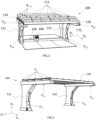
- FIG. 1 illustrates a case of a structure 100 according to an embodiment of the invention.
- the structure 100 comprises a solar assembly 110 comprising a plurality of photovoltaic solar panels 111.
- the photovoltaic solar panels 111 are also referred to in the literature as “photovoltaic modules”, or simply “solar panels”.
- the photovoltaic solar panels 111 comprise photovoltaic cells electrically connected in series and/or in parallel.
- the photovoltaic solar panels 111 capture a portion of the solar radiation and convert it into electricity by means of the photovoltaic cells.
- the photovoltaic cells comprise semiconductors.
- the semiconductors comprise, for example, silicon, such as amorphous, monocrystalline or polycrystalline silicon.
- the semiconductors include copper indium selenide (CuIn(Se) 2 , also called CIS), copper indium gallium selenide (CuInGa(Se) 2 , also called CIGS), or cadmium telluride (CdTe).
- the photovoltaic cells include a perovskite cell or organic photovoltaic cells such as polymer photovoltaic cells. For example, the photovoltaic cells are arranged in the form of plates.
- the solar assembly 110 has a generally rectangular shape.
- the dimensions of the solar assembly are for example between 2.5 m and 7 m for a first side extending in a direction substantially parallel to the second direction D 2 and between 5 m and 15 m for a second side extending in a direction substantially parallel to the first direction D 1 .
- the mass of the solar assembly is for example between 150 kg and 400 kg.
- the mass of the solar assembly 110 corresponds for example to the sum of the masses of the solar panels 111. According to another example, the mass of the solar assembly 110 corresponds to the sum of the masses of the solar panels and their respective solar supports 200.
- the solar panels 111 of the solar assembly 110 are spaced from each other in the first direction D1 or a direction parallel to this direction.
- the solar panels 111 of the solar assembly 110 may also be spaced from each other in the second direction D2 or a direction parallel to this direction.
- the solar assembly 110 comprises solar panels 111 spaced in the first direction D1 or a direction parallel to this direction and solar panels 111 spaced in the second direction D2 or a direction parallel to this direction.
- the solar panels are distributed optimally to balance the load on the support assembly 120.
- This advantageous distribution is for example obtained when the solar panels have regular spacings from each other in the first direction D 1 and/or the second direction D 2 and/or directions parallel to these directions.
- the solar panels 111 are arranged in rows R 1, x .
- the notation “R 1, x ” refers to the number of rows of solar panels in the structure 100.
- the figure 1 illustrates a case in which the structure comprises four rows of solar panels R 1, 4 .
- the number of rows may be lower or higher, depending on the size of the structure, the weight of the solar panels and the distribution of the panels generating specific constraints on the support assembly 120.
- the solar panels are spaced along the first direction D 1 and/or the second direction D 2 and/or directions parallel to these directions to allow the solar panels to be tilted along a plurality of directions in space.
- the spacing is for example advantageously chosen so that the solar panels 111 do not interfere with each other when they are tilted.
- the solar panels 111 are tiltable independently of each other.
- the solar panels 111 of each row of solar panels R 1, x are tiltable at identical angles for the panels of the same row of solar panels R 1, x and regardless of the inclination of the solar panels 111 of another row of solar panels R 1, x.
- the solar assembly 110 comprises gutters.
- the gutters are for example mounted around the solar panels 111.
- the gutters form for example a frame around the solar panels 111.
- the gutters are for example between 5 cm and 20 cm wide.
- the gutters comprise for example curved edges to allow rainwater to flow.
- the gutters comprise for example openings to allow rainwater to drain out of said gutters.
- the openings are for example provided in the corners of the frame formed by the gutters around the solar panels 111.
- the solar assembly is capable of being in at least one operational configuration in which it is fixed relative to the primary supports 121, 122 and in which each solar panel 111 has at least one support zone on the support assembly 120.
- the solar panels 111 may have a plurality of support points or support zones with the support assembly 120.
- the solar panels 111 are for example supported on a secondary structure 130 of the support assembly 120.
- the two support zones at which the solar assembly rests on the supports 120, 130 are, for example, spaced apart in the second direction D 2 .
- the solar assembly 110 comprises at least one solar support 200.
- Each solar panel 111 rests for example on a solar support 200, or on a plurality of solar supports 200.
- the solar supports 200 are for example connected to the activation means M act to vary at least one length of a longitudinal element of said solar support 200 in a direction substantially parallel to the third direction D 3 .
- This is for example a mechanical connection and an electrical connection to control an inclination of a solar panel 111 or of a solar support 200 to which a solar panel 111 is mechanically connected or on which it rests.
- An advantage is to vary the angles of the solar panels by means of the activation means.
- Another advantage is to vary the inclination of the solar panels while keeping the 120 support assembly fixed.
- the solar support 200 comprises a longitudinal element resting on a first secondary beam P s2 over its entire length. This is for example the first longitudinal element L 1 .
- each solar support 200 comprises a longitudinal element having a plurality of support zones with a plurality of first secondary beams P s2 . This is for example the first longitudinal element L 1 .
- the solar assembly comprises sensors.
- the sensors are for example brightness sensors.
- the brightness sensors are for example arranged between the solar panels 110.
- the sensors comprise pressure sensors, such as anemometers for measuring wind pressure on the solar assembly.
- the structure 100 comprises a support assembly 120 comprising at least the two primary supports 121, 122.
- the primary supports 121, 122 are spaced apart along the first direction D 1 .
- the first direction D 1 is for example linked to the primary supports 121, 122.
- linked to the primary supports is meant that the first direction D 1 depends on the positioning of the primary supports 121, 122.
- the first direction D 1 corresponds to a direction along which the two primary supports 121, 122 are spaced apart.
- the support assembly 120 comprises a secondary structure 130 for supporting the photovoltaic solar panels 111.
- the secondary support 130 comprises a plurality of first secondary beams P s1 which extend in directions substantially parallel to the first direction D 1 .
- the secondary support 130 has for example a substantially rectangular shape.
- the first secondary beams P S1 each have a support zone on each second primary beam P p2 of each primary support 121, 122.
- the support point or support area of at least one first secondary beam P s 1 on the second beam primary beam P p2 is located on an upper surface of said second primary beam P p2 .
- the first secondary beam P s1 rests for example on said second primary beam P p2 , for example at one of the ends of said first secondary beam P s1 .
- the first secondary beam P s1 has a plurality of support points or support zones with the second primary beam P p2 .
- This is for example a support zone on an upper surface of the second primary beam P p2 and a support zone on a lower surface of the second primary beam P p2 .
- At least one support zone has for example a mechanical connecting element for securing the two beams, for example one or more screws.
- the solar panels 111 of the solar assembly 110 rest for example on the first secondary beams P s1 of the secondary support 130 in a support zone. This is for example a support zone extending along the longitudinal axis of the first secondary beam P s1 .
- the solar panels 111 of the solar assembly 110 have at least one mechanical connection with the support assembly 120.
- Each mechanical connection 120, 130 keeps the solar panels 111 supported on the support assembly 120. This is for example a mechanical connection at the support zones of each solar panel 111 with a first secondary beam P s1 .
- each mechanical connection comprises a connection among the following examples: a pivot connection, a sliding connection, a recess, a sliding pivot connection, a flat support, a spherical connection or a ball joint connection.
- the mechanical connection comprises for example an intermediate part which connects a support zone of the solar assembly to a receiving zone of the supports 120, 130.
- the secondary structure 130 rests for example on the primary supports 121, 122 at several support points or support zones.
- the secondary structure 130 comprises a plurality of secondary beams P s which extend substantially parallel to the first direction D 1 .
- the solar panels 111 of the solar assembly 110 have at least one mechanical connection with the support assembly 120.
- Each mechanical connection 120, 130 maintains the solar panels 111 supported on the support assembly 120.
- each mechanical connection comprises a connection from the following examples: a pivot connection, a sliding connection, a recess, a sliding pivot connection, a flat support, a spherical connection or a ball joint connection.
- the mechanical connection comprises for example an intermediate part which connects a support zone of the solar assembly to a receiving zone of the supports 120, 130.
- the solar panels 111 of the solar assembly 110 are capable of being fixed to the secondary support 130 in fixed reception areas. These are, for example, fixed reception areas positioned on the first secondary beams P s1 of the secondary support 130. These are, for example, reception areas spaced apart in the first direction D 1 , the second direction D 2 , or directions substantially parallel to these directions.
- the receiving zones correspond for example to connection points between the sides of the solar panels 111 and a longitudinal portion of the first secondary beams P s2 .
- the receiving zones are arranged on the secondary support 130 so as to allow an optimal inclination of the solar assembly.
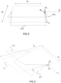
- the solar assembly rests on the secondary support 130 and is connected to said support assembly 130 so as to allow primary angles ⁇ x and secondary angles ⁇ x formed by the solar panels 111 to be varied with a reference plane P x around a first axis X x and around a second axis YX.
- At least one solar panel 111 is mechanically connected to the secondary support 130 via one or more connecting parts. These are, for example, ball joints connected to a ring, each ring being in sliding connection with a guide.
- the support assembly 120 comprises, for example, actuators, such as jacks. pneumatic, hydraulic or electric to vary the position of the rings along the guides and thus vary the primary angles ⁇ x and the secondary angles ⁇ x of the solar panels 111.
- the solar assembly 110 is in an operational configuration in which the solar panels 111 form a primary angle ⁇ x between -10° and 10° with the reference plane P 1 around a first axis X 1 parallel to the first direction.
- the solar assembly 110 is in an operational configuration in which the solar panels 111 form a secondary angle ⁇ x between -10° and 10° with the reference plane P 1 and around the second axis Y 1
- the solar assembly 110 is in an operational configuration in which the solar panels 111 form a primary angle ⁇ x between -10° and 10° with the reference plane P 1 around the first axis X 1 and in which it forms a secondary angle ⁇ x between -10° and 10° with the reference plane P 1 around the second axis Y 1 .
- An advantage of forming angles whose values are included in the above-mentioned intervals is to limit the wind resistance of the solar assembly, and therefore to limit the need for ballast and reinforcements of the structure to ensure its stability.
- the solar assembly 110 is capable of being in a configuration in which the inclination of at least one solar panel 111 is variable according to the third direction D 3 .
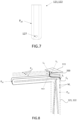
- At least one primary support 121,122 delimits a first cavity C1 .
- the first cavity C1 extends for example inside a first primary beam Pp1 of a primary support 121,122.
- the first cavity C1 extends in the first primary beam Pp1 and in the second primary beam Pp2 of at least one primary support 121,122.
- At least one primary support 121,122 comprises an internal structure S i .
- the internal structure Si is for example arranged in the first cavity C 1 .
- the internal structure Si comprises for example steel, wood, or any other suitable rigid material.
- the internal structure Si comprises for example I-beams with a standardized profile, also designated by the acronym IPN.
- the internal structure Si comprises for example two first longitudinal portions, first ends of which are in contact with the ground and comprising second ends on which a second longitudinal portion rests.
- the first longitudinal portions of the internal structure Si intersect at a predefined angle. According to one case, this crossing is carried out near the first ends. In this case, an advantage is to improve the stability on the ground of the internal structure S i . According to another case, this crossing is carried out near the second ends. In this case, this makes it possible to reinforce the stability of the second longitudinal portion which rests on the second ends of the first longitudinal portions.
- each primary support 121, 122 comprises a base.
- the bases serve for example as anchor points to the ground for the support assembly 120.
- the bases extend for example in a direction substantially parallel to the second direction D 2 .
- the bases extend for example opposite the second primary beams P p2 .
- the bases may comprise an elongated portion extending in a direction substantially parallel to the second direction D 2 .
- One advantage is to improve the stability of the structure 100 by increasing the ground contact area of the bases.
- the support assembly 120 comprises foundations.
- the internal structure Si is for example fixed to the foundations.
- the foundations are for example anchored to the ground.
- the foundations make it possible to reinforce the stability on the ground of the internal structure S i .
- the support assembly comprises low ballast portions connected to the bases.
- this is a portion extending in the second direction and in a direction opposite to a direction in which extends the second primary beam P p2 of a primary support 121, 122.
- the lower ballast portions comprise for example the ballast material M L .
- ballast portions contribute to the stability of the structure, in particular by counterbalancing any forces due to the geometry of the primary supports 121, 122 and to the loads of the solar panels on the support assembly 120.
- the lower ballast portions open onto the first cavity C1 .
- the internal structure Si has various shapes, such as a C shape, or an inverted U shape.
- the ground support points of the internal structure Si are for example located on the branch of the C or the inverted U in contact with the ground.
- An advantage of implementing such shapes for the internal structure Si is to reinforce its stability on the ground.
- this embodiment of the invention is not limited to the aforementioned shapes.
- the invention is likely to be implemented with any type of internal structure Si whose shape is adapted to ensure optimum stability.
- the support assembly 120 comprises an additional structure connected to the external structure S e .
- the additional structure contributes to the stability of the structure 100.
- it comprises the same materials as the internal structure S i .
- it is implemented in addition to or as a replacement for the internal structure S i .
- it is connected to the external surface of the external structure S e .
- the support assembly comprises a ballast material M L .
- the ballast material M L promotes the maintenance of the structure 100 in a mounted and stable position.
- the support assembly comprises for example between 1 tonne and 4 tonnes of ballast material M L .
- the ballast material M L is for example distributed in internal cavities of the structural elements included by the support assembly 120, such as the first cavity C 1 .
- each primary support 121, 122 comprises between 1 tonne and 1.5 tonnes of ballast material M L .
- the ballast material M L is for example also distributed in these other structural elements.
- the ballast material M L comprises, for example, a porous ballast material.
- porous material means a solid material containing pores or small cavities that can contain one or more fluids in liquid or gaseous form.
- the ballast material M L comprises, for example, a granular agglomerate.
- the ballast material M L comprises, for example, an aggregate, such as sand, gravel or gravel.
- the first primary beam P p1 of at least one primary support 121,122 comprises the ballast material M L .
- the bases comprise an internal cavity filled with the ballast material M L .
- the internal cavities of the bases open onto the first cavity C 1 .
- At least one primary support 121, 122 comprises an opening 127.
- the opening 127 is for example circular in shape.
- the opening is for example formed in the second primary beam P p2 of a primary support 121, 122.
- the opening 127 opens onto the first cavity C1 .
- An advantage is to allow the routing of rainwater into the porous ballast material.
- the absorption of rainwater by the porous ballast material makes it possible to increase the density of the material, and consequently to reinforce the stability of the structure 100.
- the density of sand is approximately 1600 km -3
- the density of wet sand is approximately 1900 kg.m -3 .
- At least one second primary beam P p2 comprises a gutter for conveying rainwater into the opening 127.
- the gutter comprises, for example, curved edges to facilitate the flow of water.
- the opening 127 is, for example, formed in the gutter at one end of the second primary beam P p2 .
- the opening 127 comprises a filter.
- the support assembly comprises at least one opening sized to allow the passage of the ballast material M L .
- This is for example an opening positioned on an upper portion of a primary support 121, 122.
- the opening is for example formed in the first primary beam P p1 of a primary support 121, 122.
- the opening 127 is sized to allow the introduction of the ballast material M L into a pillar 122,132 of the support assembly.
- the support assembly 120 comprises an external structure S e .
- the external structure S e delimits boundaries of an interior volume of the support assembly 120, which comprises for example the first cavity C 1 .
- the external structure S e contains for example the internal structure Si and the ballast material M L .
- the external structure S e comprises metal.
- the external structure S e comprises for example a steel alloy, such as a galvanized steel.
- the external structure S e comprises a composite material.
- the support assembly 120 comprises a covering.
- the covering at least partially covers the external structure S e .
- the thickness of the covering is for example between 250 ⁇ m and 450 ⁇ m.
- the weight of the covering is for example between 350 gm -2 and 550 gm 2 .
- the covering of the external structure S e comprises a photovoltaic film.
- a photovoltaic film This is for example a film comprising organic polymers.
- the support assembly 120 comprises a waterproof coating.
- the waterproof coating is applied to an internal surface of the external structure.
- the internal surface delimits for example the first cavity C 1 .
- the coating is applied to an external surface of the external structure.
- One advantage is to reduce the risk of rusting of the external structure caused by external humidity or by humidity coming from the recovery of rainwater and ballast material.
- the support assembly 120 comprises support plates.
- the support plates are for example fixed to the ground.
- the external structure S e is for example fixed to the support plates.
- the support plates are for example supported on each other and each fixed to the ground.
- the support assembly 120 comprises a connecting block 140.
- the connecting block 140 connects the supports 120, 130.
- the connecting block 140 is for example a block of substantially rectangular shape.
- the connecting block 140 is for example in contact with the ground.
- the connecting block 140 is for example fixed to the ground.
- the connecting block 140 comprises at least one accumulator 150.
- the accumulator 150 makes it possible to store electrical energy.
- the accumulator comprises, for example, a battery.
- the batteries comprise, for example, lithium-ion batteries.
- the accumulator 150 is a solid electrolyte battery. It is, for example, an entirely solid silicon battery.
- the invention is not limited to the aforementioned battery technologies. Any suitable means of storing electrical energy may be implemented within the scope of the invention.
- the connecting block 140 comprises a plurality of accumulators 150.
- accumulators 150 are, for example, batteries of the same technologies, or a combination of several battery technologies combined with each other.
- the connecting block 140 comprises interior compartments.
- the interior compartments make it possible, for example, to accommodate one or more accumulators 150.
- the connecting block 140 comprises a second cavity C 2 .
- the connecting block comprises a second cavity
- the connecting block comprises a second cavity
- the second cavity extends for example inside the connecting block 140 and towards the supports 120, 130.
- the connecting block 140 comprises the ballast material M L .
- the ballast material M L is for example arranged in the second cavity C 2 .
- the second cavity C2 is connected to the first cavity C1 .
- the first cavity C1 and the second cavity C2 form a single cavity.
- An advantage is to allow fluid communication between the first cavity C 1 and the second cavity C 2 .
- an advantage is to allow the flow of water in these two cavities to increase the density of the material and therefore reinforce the stability of the structure.
- the connecting block 140 comprises at least one converter.
- This is for example a solar converter, also called a photovoltaic inverter.
- the converter is electrically connected to the solar panels 110.
- the converter makes it possible to convert the direct current produced by the solar panels 110 into alternating current.
- the converter is for example an inverter called “ongrid” or an autonomous inverter called “offgrid”.
- the converter is for example a micro-inverter, a string inverter, a battery inverter, or even a hybrid inverter.
- the converter is for example placed in an interior compartment of the connecting block 140.
- the converter is installed in a sealed interior compartment in the connecting block 140. It is for example positioned near the accumulator 150 in the connecting block 140.
- the accumulator 150 and the converter are for example positioned in the same compartment, or in different communicating compartments to allow the passage of electrical cables.
- the converter is positioned in a primary support 121, 122 of the support assembly 120. It is for example positioned in a lower portion of a primary support 121, 122, for example in a base.
- the structure 100 comprises electrical cables.
- the electrical cables make it possible to electrically connect various equipment, such as the solar assembly, the inverter and the accumulator 150.
- the support assembly 120 comprises electrical cable compartments.
- the electrical cable compartments are for example arranged inside a primary support 121, 122 and/or inside the connecting block 140, for example on an internal face of a primary support 121, 122 and/or of the connecting block 140 and of the primary supports 121, 122.
- the electrical cable compartments make it possible to protect the electrical cables from possible deterioration, for example by contact with the ballast material or with rainwater conveyed into the cavities.
- the electrical cable compartments extend for example through the connecting block 140 and through the primary supports 121, 122 to the solar panels 111 of the solar assembly 110 to allow the passage of the electrical cables from the solar panels 111 to the inverter and to the batteries arranged in the connecting block 140.
- the cable compartments are for example accessible from the outside to allow maintenance of the electrical cables.
- the support assembly comprises means of access to the compartments, such as means of opening the compartments arranged on the external structure.
- the connecting block 140 comprises a hollow portion formed in an upper part.
- the hollow portion is for example of substantially rectangular shape.
- the hollow portion is for example capable of receiving soil to accommodate plants.
- the primary supports 121, 122 comprise means for conveying rainwater to the hollow portion of the support block 140. This is, for example, a dedicated channel extending through the first cavity C1 and the second cavity C2 .
- the connecting block 140 comprises a transparent material. This is, for example, plexiglass.
- connection block such as batteries and electrical cables. This allows in particular to visually detect any possible fault in the installation and to plan maintenance operations if necessary.
- the connecting block 140 comprises several compartments that can be opened to accommodate one or more converters, the batteries and the electrical cables.
- the compartments are for example accessible by an operator to allow maintenance operations.
- the structure 100 comprises a “Maximum power point tracker” system, also designated by the acronym “MPPT system”.
- One advantage is to get maximum possible power from the solar array.
- the support assembly comprises a vehicle charging station 160.
- the vehicle charging station 160 is for example positioned on the connecting block 140.
- the connecting block 140 comprises for example a support for supporting the vehicle charging station 160.
- the support is for example rectangular in shape.
- the support is for example positioned on the upper part of the connecting block 140.
- the vehicle charging station is electrically connected to the accumulator 150.
- One advantage is that a portion of the stored electrical energy can be used to recharge a vehicle parked under the structure.
- the support assembly 120 comprises a plurality of vehicle charging terminals 160 electrically connected to the accumulator 150.
- the vehicle charging station 160 is electrically connected to the converter.
- the vehicle charging station 160 is connected to the electrical network.
- the connecting block 140 comprises means for receiving at least one vehicle charging terminal 160.
- receiving means comprise for example a cavity sized to receive the vehicle charging terminal.
- the receiving means comprise means for fixing the vehicle charging terminal to the connecting block 140.
- the structure 100 comprises a lighting system.
- the lighting system comprises for example a set of LEDs, from the English “Light Emitting Diodes”.
- the lighting system is for example positioned on the upper block 121, 122 of a support 120, 130.
- the lighting system is electrically connected to the accumulator 150.
- the lighting system is electrically connected to the converter.
- the lighting system is connected to the electrical network.
- the support assembly 120 is modular.
- module is meant that elements of the support assembly 120 can be disassembled and replaced or not, or that new elements can be added to the support assembly 120, for example additional primary supports or cable passage elements.
- the support assembly 120 comprises for example mechanical elements capable of receiving at least one additional modular support element.
- the mechanical elements comprise for example connecting elements capable of receiving screws or any other means of connecting or mechanical assembly for adding an additional support element.
- the mechanical elements are for example capable of receiving modular elements allowing the passage of electrical cables, for example connecting the two primary supports 121, 122.
- the modular elements comprise elements capable of receiving another primary support. In this case, it is for example possible to dismantle one of the initial primary supports.
- the support assembly 120 comprises mechanical elements capable of receiving the connecting block 140. These are, for example, mechanical connecting elements positioned on the primary supports 121, 122.
- the solar assembly 110 is modular.
- module is meant that elements of the solar assembly 110 can be disassembled and replaced or not, or that new elements can be added to the solar assembly 110, for example additional solar panels.
- the solar assembly 110 comprises for example additional solar supports 200 for receiving additional solar panels 111, additional mechanical elements for receiving additional solar supports 200, or additional mechanical elements other than the solar supports 200 for receiving one or more additional solar panels 111.
- the structure 100 comprises a control system.
- the control system makes it possible to vary the primary angles ⁇ x and the secondary angles ⁇ x of the solar panels of the solar assembly relative to a reference plane P x .
- the control system comprises, for example, a calculator for implementing functions or calculations according to various parameters.
- the parameters comprise, for example, measurements made by sensors of the solar assembly such as anemometers or brightness sensors.
- the functions implemented are, for example, functions for comparing values measured by the sensors with threshold values. For example, when the anemometers measure a wind force greater than a given threshold, the control system controls means for actuating the connection means between the solar panels 111 of the solar assembly 110 and the secondary support 130.
- the control system activates, for example, the activation means M act .
- the activation means M act comprise, for example, a control console which is, for example, integrated into the structure and powered by the solar panels 111.
- the activation means M act can for example be controlled by a user to vary the angles of the solar panels 111 of the solar assembly 110.
- the structure comprises a computer comprising a pre-recorded program for controlling the solar panels, for example according to date and time parameters, or according to parameters measured by sensors positioned on the structure.
- brightness sensors can be positioned at different points on the structure and the brightness data measured by these sensors make it possible to determine an optimal orientation of the solar panels to obtain optimal electricity production.
- the computer controls for example the activation means M act to vary the orientation of the solar panels according to these parameters.
- the activation means M act comprise a local control interface for controlling orientations of the solar panels 111 of the solar assembly 110.
- the activation means M act are connected to a data network to control orientations of the solar panels of the structure from an interface connected to a remote server.
- the structure 100 comprises a communication interface for receiving data and controlling orientations of the solar panels 111 of the solar assembly 110 according to the processing of these data received by a computer.
- data are, for example, data measured locally by sensors, or data received from a remote database, such as forecast weather data.
- the activation means M act make it possible to vary the primary angles ax and the secondary angles ⁇ x formed by the solar panels 111 with a reference plane Px.
- the control system activates, for example, jacks to bring each solar panel 111 into a reference plane P x when the anemometers measure a wind force greater than a given threshold.
- control system controls the movement of the solar panels 111 of the solar assembly 110 until that the anemometers transmit to the calculator a wind force value lower than a given threshold.
- the control system controls the movement of the solar panels 111 of the solar assembly 110 when the computer receives brightness values below a given threshold.
- the solar assembly comprises brightness sensors which transmit, for example, measured values to the computer at a given frequency.
- the computer implements, for example, functions for comparing the values transmitted by the brightness sensors with thresholds at a given frequency, for example every minute.
- the control system controls the movement of the solar panels 111 of the solar assembly 110 until the values measured by the brightness sensors are above a given threshold.
- the sensors transmit, for example, the brightness values at a higher frequency when the solar assembly is moved.
- One advantage is to adjust the position of the solar panels of the solar array when the solar panels no longer receive enough solar radiation to allow sufficient electricity production, for example due to the presence of a shadow at certain times of the day.
- the control system controls the power supply of the vehicle charging stations.
- the control system controls the power supply of the vehicle charging stations according to various parameters.
- the parameters include for example a charge level of the accumulator 150, an electricity price, a time of day or measurements of the sensors positioned on the solar assembly.
- the computer calculates for example functions of these different parameters to execute a control law to power the vehicle charging station.
- the control law makes it possible for example to power the vehicle charging station either directly from the converter, or from the accumulator or from the electrical network, according to these different parameters.
- One advantage is to optimize the energy management of the system and reduce the consumption cost while allowing a constant power supply to the vehicle charging stations.
Landscapes
- Engineering & Computer Science (AREA)
- Architecture (AREA)
- Civil Engineering (AREA)
- Structural Engineering (AREA)
- Physics & Mathematics (AREA)
- Life Sciences & Earth Sciences (AREA)
- Sustainable Development (AREA)
- Sustainable Energy (AREA)
- Thermal Sciences (AREA)
- Chemical & Material Sciences (AREA)
- Combustion & Propulsion (AREA)
- Mechanical Engineering (AREA)
- General Engineering & Computer Science (AREA)
- Body Structure For Vehicles (AREA)
- Photovoltaic Devices (AREA)
Applications Claiming Priority (1)
| Application Number | Priority Date | Filing Date | Title |
|---|---|---|---|
| FR2304542A FR3148453B1 (fr) | 2023-05-05 | 2023-05-05 | Structure photovoltaïque pour ombrager une zone de stationnement de vehicules |
Publications (1)
| Publication Number | Publication Date |
|---|---|
| EP4459864A1 true EP4459864A1 (de) | 2024-11-06 |
Family
ID=87554326
Family Applications (1)
| Application Number | Title | Priority Date | Filing Date |
|---|---|---|---|
| EP24174383.0A Pending EP4459864A1 (de) | 2023-05-05 | 2024-05-06 | Photovoltaikstruktur zum beschatten eines fahrzeugparkbereichs |
Country Status (2)
| Country | Link |
|---|---|
| EP (1) | EP4459864A1 (de) |
| FR (1) | FR3148453B1 (de) |
Citations (9)
| Publication number | Priority date | Publication date | Assignee | Title |
|---|---|---|---|---|
| EP1626140A2 (de) * | 2004-08-09 | 2006-02-15 | Extel S.r.l. | Unterstand für Kraftfahrzeuge |
| WO2008084102A2 (de) * | 2007-01-12 | 2008-07-17 | Paul Schlossbauer | Vorrichtung aus einer mehrzahl von tragwerksmodulen und vorrichtung zur nachführung von modulen zur umwandlung oder bündelung von sonnenenergie |
| FR2949243A1 (fr) | 2009-08-18 | 2011-02-25 | Onet Technologies En | Dispositif de type ombriere de parking photovoltaique |
| US20110290306A1 (en) * | 2010-04-26 | 2011-12-01 | Todd Roberts | Solar array configurations |
| US20120235017A1 (en) * | 2010-03-29 | 2012-09-20 | Sedona Energy Labs, Limited Company | Counterbalanced dual axis solar tracking system |
| US20140246903A1 (en) * | 2011-10-17 | 2014-09-04 | Tempero 2000 S.L. | Solar parking module with integrated ev charging station |
| US20200220376A1 (en) * | 2019-01-09 | 2020-07-09 | SkyHook Solar Corp | Solar Powered Charging Station |
| US20210211091A1 (en) * | 2018-04-10 | 2021-07-08 | Barry Sgarrella | Dynamically Shifting Photovoltaic Panel Array Apparatus |
| DE102022118730A1 (de) * | 2022-07-26 | 2022-12-29 | Meyer Burger (Germany) Gmbh | Solaranlage mit Solartracker |
-
2023
- 2023-05-05 FR FR2304542A patent/FR3148453B1/fr active Active
-
2024
- 2024-05-06 EP EP24174383.0A patent/EP4459864A1/de active Pending
Patent Citations (9)
| Publication number | Priority date | Publication date | Assignee | Title |
|---|---|---|---|---|
| EP1626140A2 (de) * | 2004-08-09 | 2006-02-15 | Extel S.r.l. | Unterstand für Kraftfahrzeuge |
| WO2008084102A2 (de) * | 2007-01-12 | 2008-07-17 | Paul Schlossbauer | Vorrichtung aus einer mehrzahl von tragwerksmodulen und vorrichtung zur nachführung von modulen zur umwandlung oder bündelung von sonnenenergie |
| FR2949243A1 (fr) | 2009-08-18 | 2011-02-25 | Onet Technologies En | Dispositif de type ombriere de parking photovoltaique |
| US20120235017A1 (en) * | 2010-03-29 | 2012-09-20 | Sedona Energy Labs, Limited Company | Counterbalanced dual axis solar tracking system |
| US20110290306A1 (en) * | 2010-04-26 | 2011-12-01 | Todd Roberts | Solar array configurations |
| US20140246903A1 (en) * | 2011-10-17 | 2014-09-04 | Tempero 2000 S.L. | Solar parking module with integrated ev charging station |
| US20210211091A1 (en) * | 2018-04-10 | 2021-07-08 | Barry Sgarrella | Dynamically Shifting Photovoltaic Panel Array Apparatus |
| US20200220376A1 (en) * | 2019-01-09 | 2020-07-09 | SkyHook Solar Corp | Solar Powered Charging Station |
| DE102022118730A1 (de) * | 2022-07-26 | 2022-12-29 | Meyer Burger (Germany) Gmbh | Solaranlage mit Solartracker |
Also Published As
| Publication number | Publication date |
|---|---|
| FR3148453A1 (fr) | 2024-11-08 |
| FR3148453B1 (fr) | 2025-10-17 |
Similar Documents
| Publication | Publication Date | Title |
|---|---|---|
| US9954478B2 (en) | Solar array support methods and systems | |
| US9077280B2 (en) | Solar array support methods and systems | |
| AU2009246194B2 (en) | Solar array support methods and systems | |
| US8429861B2 (en) | Solar array support methods and systems | |
| US9627921B2 (en) | Solar parking module with integrated EV charging station | |
| CN202993633U (zh) | 太阳能模块附接装置 | |
| KR102848745B1 (ko) | 적어도 1개의 광기전력 소자를 갖는 컬럼, 및 컬럼 상의 광기전력 소자의 용도 | |
| EP3593064B1 (de) | Solarmatte | |
| FR2949243A1 (fr) | Dispositif de type ombriere de parking photovoltaique | |
| EP4243278A1 (de) | System zum verbinden von photovoltaikpaneelen mit einer struktur mit aufgehängten kabeln | |
| EP2773912B1 (de) | Solarpark, solartisch für einen solchen solarpark und verfahren zur herstellung solch eines solarparks | |
| FR3148453A1 (fr) | Structure photovoltaïque pour ombrager une zone de stationnement de vehicules | |
| CN103283035B (zh) | 太阳光跟踪装置 | |
| FR2960343A1 (fr) | Systeme photovoltaique tubulaire | |
| EP1860387A1 (de) | Sonnennachführer mit Gelenkarmen | |
| OA22126A (en) | Photovoltaic Green Roofs And Facades. | |
| WO2024083468A1 (fr) | Toitures et facades vegetalisees photovoltaïques | |
| KR102240651B1 (ko) | 태양광 발전장치의 시공구조 | |
| WO2018220655A1 (en) | A tilt alterable solar modules mounting structure | |
| FR3055074A1 (fr) | Trackers solaires- tables de cellules photovoltaiques orientees par roues et galets. toutes les fonctions sont au sol | |
| FR3151318A1 (fr) | Ensemble de stockage d’eau | |
| WO2025252852A1 (fr) | Structure de panneau photovoltaïque comprenant un dispositif de réglage d'orientation du panneau photovoltaïque | |
| Ross et al. | South Pole expedition | |
| FR3097244A1 (fr) | Bâtiment photovoltaïque | |
| EP3240977A1 (de) | Reflektorfeldinfrastruktur |
Legal Events
| Date | Code | Title | Description |
|---|---|---|---|
| PUAI | Public reference made under article 153(3) epc to a published international application that has entered the european phase |
Free format text: ORIGINAL CODE: 0009012 |
|
| STAA | Information on the status of an ep patent application or granted ep patent |
Free format text: STATUS: THE APPLICATION HAS BEEN PUBLISHED |
|
| AK | Designated contracting states |
Kind code of ref document: A1 Designated state(s): AL AT BE BG CH CY CZ DE DK EE ES FI FR GB GR HR HU IE IS IT LI LT LU LV MC ME MK MT NL NO PL PT RO RS SE SI SK SM TR |
|
| STAA | Information on the status of an ep patent application or granted ep patent |
Free format text: STATUS: REQUEST FOR EXAMINATION WAS MADE |
|
| 17P | Request for examination filed |
Effective date: 20250429 |
|
| RAP1 | Party data changed (applicant data changed or rights of an application transferred) |
Owner name: PROPERPHI |