EP4459853A1 - Bidirektionale stromversorgung, bidirektionaler resonanzwandler und verfahren zur herstellung eines bidirektionalen resonanzwandlers - Google Patents
Bidirektionale stromversorgung, bidirektionaler resonanzwandler und verfahren zur herstellung eines bidirektionalen resonanzwandlers Download PDFInfo
- Publication number
- EP4459853A1 EP4459853A1 EP24166256.8A EP24166256A EP4459853A1 EP 4459853 A1 EP4459853 A1 EP 4459853A1 EP 24166256 A EP24166256 A EP 24166256A EP 4459853 A1 EP4459853 A1 EP 4459853A1
- Authority
- EP
- European Patent Office
- Prior art keywords
- side switches
- primary
- port
- control
- power supply
- Prior art date
- Legal status (The legal status is an assumption and is not a legal conclusion. Google has not performed a legal analysis and makes no representation as to the accuracy of the status listed.)
- Pending
Links
Images





Classifications
-
- H—ELECTRICITY
- H02—GENERATION; CONVERSION OR DISTRIBUTION OF ELECTRIC POWER
- H02M—APPARATUS FOR CONVERSION BETWEEN AC AND AC, BETWEEN AC AND DC, OR BETWEEN DC AND DC, AND FOR USE WITH MAINS OR SIMILAR POWER SUPPLY SYSTEMS; CONVERSION OF DC OR AC INPUT POWER INTO SURGE OUTPUT POWER; CONTROL OR REGULATION THEREOF
- H02M1/00—Details of apparatus for conversion
- H02M1/0067—Converter structures employing plural converter units, other than for parallel operation of the units on a single load
- H02M1/007—Plural converter units in cascade
-
- H—ELECTRICITY
- H02—GENERATION; CONVERSION OR DISTRIBUTION OF ELECTRIC POWER
- H02M—APPARATUS FOR CONVERSION BETWEEN AC AND AC, BETWEEN AC AND DC, OR BETWEEN DC AND DC, AND FOR USE WITH MAINS OR SIMILAR POWER SUPPLY SYSTEMS; CONVERSION OF DC OR AC INPUT POWER INTO SURGE OUTPUT POWER; CONTROL OR REGULATION THEREOF
- H02M7/00—Conversion of AC power input into DC power output; Conversion of DC power input into AC power output
- H02M7/66—Conversion of AC power input into DC power output; Conversion of DC power input into AC power output with possibility of reversal
- H02M7/68—Conversion of AC power input into DC power output; Conversion of DC power input into AC power output with possibility of reversal by static converters
- H02M7/72—Conversion of AC power input into DC power output; Conversion of DC power input into AC power output with possibility of reversal by static converters using discharge tubes with control electrode or semiconductor devices with control electrode
- H02M7/79—Conversion of AC power input into DC power output; Conversion of DC power input into AC power output with possibility of reversal by static converters using discharge tubes with control electrode or semiconductor devices with control electrode using devices of a triode or transistor type requiring continuous application of a control signal
- H02M7/797—Conversion of AC power input into DC power output; Conversion of DC power input into AC power output with possibility of reversal by static converters using discharge tubes with control electrode or semiconductor devices with control electrode using devices of a triode or transistor type requiring continuous application of a control signal using semiconductor devices only
-
- H—ELECTRICITY
- H02—GENERATION; CONVERSION OR DISTRIBUTION OF ELECTRIC POWER
- H02M—APPARATUS FOR CONVERSION BETWEEN AC AND AC, BETWEEN AC AND DC, OR BETWEEN DC AND DC, AND FOR USE WITH MAINS OR SIMILAR POWER SUPPLY SYSTEMS; CONVERSION OF DC OR AC INPUT POWER INTO SURGE OUTPUT POWER; CONTROL OR REGULATION THEREOF
- H02M3/00—Conversion of DC power input into DC power output
- H02M3/01—Resonant DC/DC converters
-
- H—ELECTRICITY
- H02—GENERATION; CONVERSION OR DISTRIBUTION OF ELECTRIC POWER
- H02M—APPARATUS FOR CONVERSION BETWEEN AC AND AC, BETWEEN AC AND DC, OR BETWEEN DC AND DC, AND FOR USE WITH MAINS OR SIMILAR POWER SUPPLY SYSTEMS; CONVERSION OF DC OR AC INPUT POWER INTO SURGE OUTPUT POWER; CONTROL OR REGULATION THEREOF
- H02M3/00—Conversion of DC power input into DC power output
- H02M3/22—Conversion of DC power input into DC power output with intermediate conversion into AC
- H02M3/24—Conversion of DC power input into DC power output with intermediate conversion into AC by static converters
- H02M3/28—Conversion of DC power input into DC power output with intermediate conversion into AC by static converters using discharge tubes with control electrode or semiconductor devices with control electrode to produce the intermediate AC
- H02M3/325—Conversion of DC power input into DC power output with intermediate conversion into AC by static converters using discharge tubes with control electrode or semiconductor devices with control electrode to produce the intermediate AC using devices of a triode or a transistor type requiring continuous application of a control signal
- H02M3/335—Conversion of DC power input into DC power output with intermediate conversion into AC by static converters using discharge tubes with control electrode or semiconductor devices with control electrode to produce the intermediate AC using devices of a triode or a transistor type requiring continuous application of a control signal using semiconductor devices only
- H02M3/33569—Conversion of DC power input into DC power output with intermediate conversion into AC by static converters using discharge tubes with control electrode or semiconductor devices with control electrode to produce the intermediate AC using devices of a triode or a transistor type requiring continuous application of a control signal using semiconductor devices only having several active switching elements
- H02M3/33573—Full-bridge at primary side of an isolation transformer
-
- H—ELECTRICITY
- H02—GENERATION; CONVERSION OR DISTRIBUTION OF ELECTRIC POWER
- H02M—APPARATUS FOR CONVERSION BETWEEN AC AND AC, BETWEEN AC AND DC, OR BETWEEN DC AND DC, AND FOR USE WITH MAINS OR SIMILAR POWER SUPPLY SYSTEMS; CONVERSION OF DC OR AC INPUT POWER INTO SURGE OUTPUT POWER; CONTROL OR REGULATION THEREOF
- H02M3/00—Conversion of DC power input into DC power output
- H02M3/22—Conversion of DC power input into DC power output with intermediate conversion into AC
- H02M3/24—Conversion of DC power input into DC power output with intermediate conversion into AC by static converters
- H02M3/28—Conversion of DC power input into DC power output with intermediate conversion into AC by static converters using discharge tubes with control electrode or semiconductor devices with control electrode to produce the intermediate AC
- H02M3/325—Conversion of DC power input into DC power output with intermediate conversion into AC by static converters using discharge tubes with control electrode or semiconductor devices with control electrode to produce the intermediate AC using devices of a triode or a transistor type requiring continuous application of a control signal
- H02M3/335—Conversion of DC power input into DC power output with intermediate conversion into AC by static converters using discharge tubes with control electrode or semiconductor devices with control electrode to produce the intermediate AC using devices of a triode or a transistor type requiring continuous application of a control signal using semiconductor devices only
- H02M3/33569—Conversion of DC power input into DC power output with intermediate conversion into AC by static converters using discharge tubes with control electrode or semiconductor devices with control electrode to produce the intermediate AC using devices of a triode or a transistor type requiring continuous application of a control signal using semiconductor devices only having several active switching elements
- H02M3/33576—Conversion of DC power input into DC power output with intermediate conversion into AC by static converters using discharge tubes with control electrode or semiconductor devices with control electrode to produce the intermediate AC using devices of a triode or a transistor type requiring continuous application of a control signal using semiconductor devices only having several active switching elements having at least one active switching element at the secondary side of an isolation transformer
- H02M3/33584—Bidirectional converters
-
- H—ELECTRICITY
- H02—GENERATION; CONVERSION OR DISTRIBUTION OF ELECTRIC POWER
- H02M—APPARATUS FOR CONVERSION BETWEEN AC AND AC, BETWEEN AC AND DC, OR BETWEEN DC AND DC, AND FOR USE WITH MAINS OR SIMILAR POWER SUPPLY SYSTEMS; CONVERSION OF DC OR AC INPUT POWER INTO SURGE OUTPUT POWER; CONTROL OR REGULATION THEREOF
- H02M3/00—Conversion of DC power input into DC power output
- H02M3/22—Conversion of DC power input into DC power output with intermediate conversion into AC
- H02M3/24—Conversion of DC power input into DC power output with intermediate conversion into AC by static converters
- H02M3/28—Conversion of DC power input into DC power output with intermediate conversion into AC by static converters using discharge tubes with control electrode or semiconductor devices with control electrode to produce the intermediate AC
- H02M3/325—Conversion of DC power input into DC power output with intermediate conversion into AC by static converters using discharge tubes with control electrode or semiconductor devices with control electrode to produce the intermediate AC using devices of a triode or a transistor type requiring continuous application of a control signal
- H02M3/335—Conversion of DC power input into DC power output with intermediate conversion into AC by static converters using discharge tubes with control electrode or semiconductor devices with control electrode to produce the intermediate AC using devices of a triode or a transistor type requiring continuous application of a control signal using semiconductor devices only
- H02M3/33569—Conversion of DC power input into DC power output with intermediate conversion into AC by static converters using discharge tubes with control electrode or semiconductor devices with control electrode to produce the intermediate AC using devices of a triode or a transistor type requiring continuous application of a control signal using semiconductor devices only having several active switching elements
- H02M3/33576—Conversion of DC power input into DC power output with intermediate conversion into AC by static converters using discharge tubes with control electrode or semiconductor devices with control electrode to produce the intermediate AC using devices of a triode or a transistor type requiring continuous application of a control signal using semiconductor devices only having several active switching elements having at least one active switching element at the secondary side of an isolation transformer
- H02M3/33592—Conversion of DC power input into DC power output with intermediate conversion into AC by static converters using discharge tubes with control electrode or semiconductor devices with control electrode to produce the intermediate AC using devices of a triode or a transistor type requiring continuous application of a control signal using semiconductor devices only having several active switching elements having at least one active switching element at the secondary side of an isolation transformer having a synchronous rectifier circuit or a synchronous freewheeling circuit at the secondary side of an isolation transformer
-
- H—ELECTRICITY
- H02—GENERATION; CONVERSION OR DISTRIBUTION OF ELECTRIC POWER
- H02M—APPARATUS FOR CONVERSION BETWEEN AC AND AC, BETWEEN AC AND DC, OR BETWEEN DC AND DC, AND FOR USE WITH MAINS OR SIMILAR POWER SUPPLY SYSTEMS; CONVERSION OF DC OR AC INPUT POWER INTO SURGE OUTPUT POWER; CONTROL OR REGULATION THEREOF
- H02M7/00—Conversion of AC power input into DC power output; Conversion of DC power input into AC power output
- H02M7/02—Conversion of AC power input into DC power output without possibility of reversal
- H02M7/04—Conversion of AC power input into DC power output without possibility of reversal by static converters
- H02M7/06—Conversion of AC power input into DC power output without possibility of reversal by static converters using discharge tubes without control electrode or semiconductor devices without control electrode
-
- H—ELECTRICITY
- H02—GENERATION; CONVERSION OR DISTRIBUTION OF ELECTRIC POWER
- H02M—APPARATUS FOR CONVERSION BETWEEN AC AND AC, BETWEEN AC AND DC, OR BETWEEN DC AND DC, AND FOR USE WITH MAINS OR SIMILAR POWER SUPPLY SYSTEMS; CONVERSION OF DC OR AC INPUT POWER INTO SURGE OUTPUT POWER; CONTROL OR REGULATION THEREOF
- H02M7/00—Conversion of AC power input into DC power output; Conversion of DC power input into AC power output
- H02M7/66—Conversion of AC power input into DC power output; Conversion of DC power input into AC power output with possibility of reversal
- H02M7/68—Conversion of AC power input into DC power output; Conversion of DC power input into AC power output with possibility of reversal by static converters
- H02M7/72—Conversion of AC power input into DC power output; Conversion of DC power input into AC power output with possibility of reversal by static converters using discharge tubes with control electrode or semiconductor devices with control electrode
-
- H—ELECTRICITY
- H02—GENERATION; CONVERSION OR DISTRIBUTION OF ELECTRIC POWER
- H02M—APPARATUS FOR CONVERSION BETWEEN AC AND AC, BETWEEN AC AND DC, OR BETWEEN DC AND DC, AND FOR USE WITH MAINS OR SIMILAR POWER SUPPLY SYSTEMS; CONVERSION OF DC OR AC INPUT POWER INTO SURGE OUTPUT POWER; CONTROL OR REGULATION THEREOF
- H02M3/00—Conversion of DC power input into DC power output
- H02M3/22—Conversion of DC power input into DC power output with intermediate conversion into AC
- H02M3/24—Conversion of DC power input into DC power output with intermediate conversion into AC by static converters
-
- Y—GENERAL TAGGING OF NEW TECHNOLOGICAL DEVELOPMENTS; GENERAL TAGGING OF CROSS-SECTIONAL TECHNOLOGIES SPANNING OVER SEVERAL SECTIONS OF THE IPC; TECHNICAL SUBJECTS COVERED BY FORMER USPC CROSS-REFERENCE ART COLLECTIONS [XRACs] AND DIGESTS
- Y02—TECHNOLOGIES OR APPLICATIONS FOR MITIGATION OR ADAPTATION AGAINST CLIMATE CHANGE
- Y02B—CLIMATE CHANGE MITIGATION TECHNOLOGIES RELATED TO BUILDINGS, e.g. HOUSING, HOUSE APPLIANCES OR RELATED END-USER APPLICATIONS
- Y02B70/00—Technologies for an efficient end-user side electric power management and consumption
- Y02B70/10—Technologies improving the efficiency by using switched-mode power supplies [SMPS], i.e. efficient power electronics conversion e.g. power factor correction or reduction of losses in power supplies or efficient standby modes
Definitions
- This invention relates to a power supply, a resonant converter and a method of manufacturing a resonant converter, and more particularly to a single-stage bidirectional power supply, a single-stage bidirectional resonant converter and a method of manufacturing a single-stage bidirectional resonant converter.
- a power supply may generally convert alternating current (AC), such as from the grid, to direct current (DC).
- AC alternating current
- DC direct current
- a two-stage approach may be used with a power factor correction (PFC) converter at the first stage to convert AC voltage to a DC voltage, followed by a DC-DC converter at the second stage to obtain the desired DC voltage.
- PFC refers to making the line current follow the shape of the line voltage.
- a PFC converter performs power factor correction as well as rectification of an AC input.
- a DC-DC converter may include a DC-AC converter that converts the source DC to AC signal, a transformer that passes the AC signal by electromagnetic induction to a secondary side of the transformer, and an AC-DC converter on the secondary side to provide the voltage level needed at the output.
- a bidirectional power supply refers to one that facilitates both AC-DC and DC-AC conversion.
- a bidirectional power supply includes an alternating current (AC) port as a source in a first mode of operation and as a load in a second mode of operation and a line-frequency rectifier/inverter including a set of diodes to function as a rectifier to rectify an AC input from the AC port in the first mode of operation and a set of switches to function as an inverter to supply the AC port in the second mode of operation.
- a bidirectional resonant converter is coupled to the line-frequency rectifier/inverter and to a direct current (DC) port.
- the bidirectional resonant converter includes a primary port with primary-side switches and a secondary side port with secondary-side switches respectively arranged on a primary and secondary side of a transformer.
- a controller controls the primary-side switches and the secondary-side switches during a first control mode by controlling a switching frequency based on a determined value while setting a time delay between control of the primary-side switches and the secondary-side switches to be a predefined time delay.
- the controller controls the primary-side switches and the secondary-side switches during a second control mode by controlling the time delay between control of the primary-side switches and the secondary-side switches based on a determined value while setting the switching frequency to be a predefined switching frequency.
- a bidirectional resonant converter includes a primary port with primary-side switches and a secondary side port with secondary-side switches respectively arranged on a primary and secondary side of a transformer.
- a controller controls the primary-side switches and the secondary-side switches during a first control mode by controlling a switching frequency based on a determined value while setting a time delay between control of the primary-side switches and the secondary-side switches to be a predefined time delay.
- the controller controls the primary-side switches and the secondary-side switches during a second control mode by controlling the time delay between control of the primary-side switches and the secondary-side switches based on a determined value while setting the switching frequency to be a predefined switching frequency.
- a method of manufacturing a bidirectional resonant converter includes coupling a line-frequency rectifier/inverter to an AC port.
- the line-frequency rectifier/inverter includes a set of diodes to function as a rectifier to rectify an AC input from the AC port in a first mode of operation and a set of switches to function as an inverter to supply the AC port in a second mode of operation.
- the method also includes coupling a bidirectional resonant converter to the line-frequency rectifier/inverter and to a direct current (DC) port.
- the bidirectional resonant converter includes a primary port with primary-side switches and a secondary side port with secondary-side switches respectively arranged on a primary and secondary side of a transformer.
- a controller is configured to control the primary-side switches and the secondary-side switches during a first control mode by controlling a switching frequency based on a determined value while setting a time delay between control of the primary-side switches and the secondary-side switches to be a predefined time delay.
- the controller is also configured to control the primary-side switches and the secondary-side switches during a second control mode by controlling the time delay between control of the primary-side switches and the secondary-side switches based on a determined value while setting the switching frequency to be a predefined switching frequency.
- a power supply to provide a DC voltage based on an AC input may typically include two separate stages to shape the input current and to regulate the DC output. Employing only a single stage may reduce the overall number of components, resulting in weight and cost savings, for example.
- a prior approach to a single-stage power supply involves a three-phase single-stage AC-DC converter. Each phase is connected to a full-bridge diode rectifier followed by an inductor-inductor-capacitor (LLC) converter that operates in boost mode by operating at switching frequencies below the series resonant frequency of the LLC resonant circuit and in buck mode by operating at switching frequencies above the series resonant frequency of the LLC resonant circuit.
- LLC inductor-inductor-capacitor
- a single-stage bidirectional power supply may be appreciated.
- Single-stage refers to the fact that active switches, whose operation is controllably varied, are only employed at one stage of the power supply, as opposed to both the PFC and DC-DC converter stages in the example of a typical two-stage power supply.
- the PFC shapes the current to follow the shape of the voltage at the first stage.
- the PFC may accomplish the current shaping via high frequency switching or without variable switching, but the switching frequency of the PFC cannot be the same as the frequency of the AC current (i.e., line current) in order to achieve the shaping.
- a DC-DC converter regulates the output voltage.
- the bidirectional converter of the single-stage bidirectional power supply accomplishes both the current shaping and output voltage regulation functions.
- a single-stage converter can be made bidirectional by employing active switches on the primary and secondary sides of the transformer.
- Embodiments detailed herein relate to a single-stage bidirectional power supply that employs an alternating combination of variable frequency and variable time delay associated with control of the switches.
- the time delay is between operation of one set of switches of a bidirectional converter (e.g., at the primary port) and operation of another set of switches of the bidirectional converter (e.g., at the secondary port).
- Variable refers to a variation from a predefined switching frequency (f swmin ) or a predefined time delay (T dpmin ).
- the predefined switching frequency may be a minimum switching frequency and the predefined time delay may be a minimum time delay.
- the predefined switching frequency may be selected from a set of predefined switching frequencies and the predefined time delay may be selected from a set of predefined time delays.
- predefined refers to the fact that the switching frequency or time delay is not determined via a feedback control.
- the control of the switches is either at a frequency other than any predefined switching frequency with the time delay at a predefined time delay, or the control of the switches is at a predefined switching frequency with the time delay other than any predefined time delay.
- This control arrangement allows for handling a wide range of input and output voltages while ensuring that the switching frequency does not vary widely. As shown in the various exemplary embodiments, variations are possible in several aspects of the configuration of the single-stage bidirectional power supply.
- FIG. 1 is a block diagram of a single-stage bidirectional power supply 100 according to one or more embodiments.
- the single-stage bidirectional power supply 100 includes an AC port 110, a line-frequency rectifier/inverter 120, a bidirectional converter 130, a DC port 140, and a controller 150.
- the current is shaped as a sine wave between the AC port 110 and the line-frequency rectifier/inverter 120, as a full-wave rectified sine wave between the line-frequency rectifier/inverter 120 and the bidirectional converter 130, and as a line (i.e., DC) between the bidirectional converter 130 and the DC port 140.
- a line i.e., DC
- Single-stage refers to the fact that only one aspect of the single-stage bidirectional power supply 100, the bidirectional converter 130, includes active switches whose operation is controllably changed.
- Bidirectional refers to the fact that power flow may be from the AC port 110 to the DC port 140 or from the DC port 140 to the AC port 110.
- the line-frequency rectifier/inverter 120 includes a set of diodes 210 and a set of switches 215 (shown in FIG. 2 ).
- the set of diodes 210 functions as a line-frequency rectifier, converting AC to rectified AC
- switches 215 function as a line-frequency inverter, converting rectified AC back to AC.
- the switches 215 of the line-frequency rectifier/inverter 120 operate at a constant AC line frequency (e.g., 60 Hertz).
- the line-frequency rectifier/inverter 120 is not a variable-frequency switching stage of the single-stage bidirectional power supply 100 in the same way as the bidirectional converter 130. Instead, switching frequency of the switches 215 of the line-frequency rectifier/inverter 120 remains at the line frequency of the AC port 110.
- the line-frequency rectifier/inverter 120 and bidirectional converter 130 may be implemented according to different embodiments, as detailed in FIGs. 2 and 5-10 .
- the bidirectional converter 130 includes at least one transformer 225 with a primary port 220 and a secondary port 230 as shown in FIG. 2 , for example.
- every embodiment includes primary-side switches 240 at the primary port 220 and secondary-side switches 250 at the secondary port 230, as also shown in FIG. 2 .
- the controller 150 controls these primary-side switches 240 and secondary-side switches 250 based on an output DC voltage at the DC port 140 and a current flowing to the bidirectional converter 130 during AC to DC conversion and based on a reference AC current or voltage and a current flowing out of the bidirectional converter 130 during DC to AC conversion.
- the line-frequency rectifier/inverter and the bidirectional converter of the present disclosure may be controlled by the same controller, or may be controlled by two controllers respectively.
- FIG. 2 is a circuit diagram of a single-stage bidirectional power supply 100 according to an exemplary embodiment.
- the controller 150 is further detailed in FIGs. 3A and 3B .
- the exemplary embodiment shown in FIG. 2 illustrates AC to DC conversion.
- the AC port 110 is shown with an AC source 201 (V AC ), such as from the grid, and the DC port 140 is shown with a load that receives an output DC voltage (V DC ).
- V AC AC source
- V DC output DC voltage
- the current iac flows from the AC port 110, as shown.
- An EMI filter 205 may be used to filter out high frequency common mode and differential mode noise from the current i AC prior to the AC input to the line-frequency rectifier/inverter 120, which is a full-bridge line frequency rectifier/inverter according to the exemplary embodiment shown in FIG. 2 .
- the set of diodes 210 includes diodes D 1 -D 4
- the set of switches 215 includes switches S I1 -S I4 .
- these switches 215 are not variable high-frequency switches (i.e., they are not controlled to operate at different high switching frequencies). In fact, they always operate at a constant AC line frequency (e.g., 60 Hertz (Hz) in the case of the line frequency being 60 Hz).
- a capacitor C B separates the line-frequency rectifier/inverter 120 and the bidirectional converter 130.
- the line-frequency rectifier/inverter 120 implemented as the full-bridge line rectifier in the AC to DC embodiment shown in FIG.
- V AC the AC source 201
- V B the voltage across the capacitor C B varies from zero to the peak of the source voltage V AC .
- the capacitance of the capacitor C B may be small in order to obtain the voltage V B as rectified AC rather than DC with AC ripple.
- the line-frequency rectifier/inverter 120 may be implemented as a full-bridge diode rectifier formed by the diodes D 1 -D 4 by disabling the switches S I1 -S I4 or by operating the switches S I1 -S I4 as synchronous rectifiers.
- the bidirectional converter 130 then converts the rectified AC voltage (V B ) to the output DC voltage (V DC ).
- the line-frequency rectifier/inverter 120 may be implemented as an inverter by operating the switches S I1 and S I3 during the positive half cycle of AC voltage and the switches S I2 and S I4 during the negative half cycle of AC voltage.
- the bidirectional converter 130 converts a DC input (V DC ) to the rectified AC voltage (V B ).
- the bidirectional converter 130 includes a primary port 220 and secondary port 230 of a transformer 225, as previously noted.
- the primary port 220 includes a primary winding 223 of N 1 turns and the secondary port 230 includes a secondary winding 227 of N 2 turns.
- the primary port 220 includes primary-side switches 240, and the primary-side switches 240 include switches S P1 -S P4 .
- the secondary port 230 includes secondary-side switches 250, and the secondary-side switches 250 includes switches S S1 -S S4 .
- the exemplary primary port 220 shown in FIG. 2 includes an inductor L R1 , inductor L M , and capacitor C R1 , which is a resonant circuit 245 that is an LLC resonant circuit.
- the primary port 220 may include a different resonant circuit 245.
- the primary port 220 may implement a CLLC or CLLLC resonant converter or a series resonant converter (SRC) consisting of an inductor and capacitor in series.
- SRC series resonant converter
- the secondary port 230 includes a blocking capacitor C B1 . As shown in FIG. 2 , secondary-side current i s flows through the blocking capacitor C B1 .
- the secondary port 230 may be dynamically modified via the relays R 1 , R 2 , and R 3 to operate with either a full-bridge or stacked half-bridge configuration.
- the configurable arrangement may facilitate outputting a wide DC output voltage range.
- the relays R 1 and R 2 may be controlled (e.g., by the controller 150) to be open (off) while the relay R 3 is closed (on) for a stacked half-bridge configuration when the value of V DC is relatively large (e.g., above a predefined threshold voltage).
- the average voltage across the blocking capacitor C B1 is equal to half the output DC voltage (V DC ) such that the voltage at the secondary terminals of the transformer 225 varies from -V DC /2 to V DC /2.
- the relays R 1 and R 2 may be controlled to be closed (on) while the relay R 3 is controlled to be open (off) for a full-bridge configuration when the value of V DC is relatively small (e.g., below the threshold voltage).
- the average voltage across the blocking capacitor C B1 is zero and the voltage at the secondary terminals of the transformer 225 varies between +V DC to -V DC .
- operation of the stacked half-bridge configuration at higher values of V DC may be similar to operation of the full-bridge configuration at lower values of V DC .
- the threshold voltage forming the basis for control of the relays R 1 , R 2 , and R 3 may depend on the voltage rating of the secondary-side switches 250.
- control of the switches 240, 250 may be alternated between a predefined switching frequency with variable time delay between the switches 240, 250 and a predefined time delay between the switches 240, 250 with variable switching frequency. Such a control scheme may reduce the overall switching frequency range requirement.
- FIGs. 3A and 3B detail aspects of the operation of the controller 150.
- FIG. 3A shows aspects of the operation of the controller 150 according to an embodiment. Specifically, functions of the controller 150 during conversion from AC to DC are shown. As shown at the bottom right of FIG. 3A , the output DC voltage (V DC ) provided by the bidirectional converter 130 at the DC port 140 is subtracted from a reference DC voltage (V DCref ) that may represent, for example, the desired DC voltage for a load at the DC port 140.
- V DC output DC voltage
- V DCref reference DC voltage
- the subtractor 303 result (E1) is provided to a voltage controller 305 that may be a proportional integral (PI) controller, for example.
- PI proportional integral
- a known PI controller combines proportional control, in which the output (V EA , as shown) is proportional to an input error (E1), and integral control, in which the output V EA is proportional to the integral of the input error E1.
- the voltage controller 305 may be regarded as an error amplifier.
- the output of the voltage controller 305, the voltage V EA is provided to a multiplier 307, along with the rectified AC voltage (V B ).
- the voltage V EA indicates an input admittance while the rectified AC voltage V B indicates the shape of the voltage.
- the output of the multiplier 307 is a reference current I ref that is provided to a subtractor 309.
- the current i BR at the input of the bidirectional converter is a pulsating current.
- a filtered current i BRf may be sensed or an average current i BR,avg may be determined as discussed with reference to FIG. 4 .
- This sensed or obtained current i BRf/ i BR,avg is subtracted from the reference current I ref at the subtractor 309, and the result (E2) is provided to a current controller 310.
- the current controller 310 may be a PI controller like the voltage controller, for example. As shown in FIG. 3A , according to an exemplary embodiment, the current controller 310 outputs a voltage V iea .
- a feed forward approach may be used. Specifically, a mapping 311 may be created between the output DC voltage (V DC ), output power at the DC port 140, AC source 201 (V AC ), and/or rectified AC voltage (V B ) and a voltage V 311 using a computation based on the known values. This mapped voltage V 311 is added to the output V 310 of the current controller 310 at the adder 312 to provide the voltage V iea . According to this feed forward approach, the required V iea may be reached in fewer control cycles and improved total harmonic distortion may be achieved.
- the current controller output V iea causes the controller 150 to output either a determined percentage time delay T dp between the switches 240, 250 at a predefined switching frequency f swmin or a determined switching frequency f sw at a predefined time delay T dpmin .
- the current controller output V iea is a positive value when the sensed or obtained current i BRf/ i BR,avg is smaller than the reference current I ref.
- the scale level V LimF is set to 0 while, at limiter 320, the scale value V LimD is a non-zero value up to an upper limit V LH .
- the current controller output V iea is a negative value when the sensed or obtained current i BRf/ i BR,avg is larger than the reference current I ref .
- the scale value V LimF is a non-zero value down to a lower limit V LL
- the scale value V LimD is set to 0.
- the gain K ⁇ converts the scale value V Limf to a frequency f f that that is subtracted from the predefined switching frequency f swmin at the subtractor 327 to provide the switching frequency f sw at which the switches 240, 250 are controlled.
- the gain K TD converts the scale value V LimD to percentage time delay T D that is added to a predefined time delay T dPmin at the adder 333 to provide the percentage time delay T dp separating control of the switches 240, 250.
- the switches 215 at the rectifier/inverter 120 are not variable high-frequency switches and are unaffected by the values of the switching frequency f sw and percentage time delay T dp determined based on the output DC voltage (V DC ) provided by the bidirectional converter 130 at the DC port 140.
- the comparator 360 compares current i AC from the AC port 110 with 0, as shown. When i AC > 0, then the comparator 360 output is high. In this case, switches Sn and S 13 are on (closed). Further, based on the inverter 365, the complementary switches S 12 and S 14 at the rectifier/inverter 120 are off (open). Alternately, when iac ⁇ 0, then the comparator 360 output is low. In this case, switches Sn and S 13 are off (open). Further, based on the inverter 365, the complementary switches S 12 and S 14 at the rectifier/inverter 120 are on (closed).
- the primary-side switches 240 lead the secondary-side switches 250 in the case of AC to DC conversion.
- the primary-side switches 240 are affected only by the switching frequency f sw
- the secondary-side switches 250 are affected by both the switching frequency f sw and the percentage time delay T dp that defines the delay in control of the secondary-side switches 250 relative to the primary-side switches 240.
- the switching frequency f sw is provided to a digital pulse width modulator (DPWM) 340 to control the frequency at which each of the primary-side switches S P1 -S P4 is turned on or off. Both the switching frequency f sw and the percentage time delay T dp are provided to a DPWM 350 affecting control of each of the secondary-side switches S S1 -S S4 .
- a comparator 355 also provides input to the DPWM 350 and controls the function of the secondary-side switches 250 to operate as synchronous rectifiers to produce a DC output. The comparator 355 compares the secondary-side current i s that flows through the blocking capacitor C B1 and 0. That is, when i s > 0, then the comparator 355 output is high. Alternately, when i s ⁇ 0, then the comparator 355 output is low.
- FIG. 3B shows aspects of the operation of the controller 150 according to an embodiment. Specifically, functions of the controller 150 during conversion from DC to AC are shown. As a comparison with FIG. 3A indicates, generation of V iea differs in FIG. 3B since the output to be controlled is at the AC port 110 rather than at the DC port 140.
- a reference generator 370 generates a reference AC current i AC,ref or a reference AC voltage V AC,ref that may represent the desired output at the AC port 110.
- a rectifier 380 provides a rectified reference AC current
- switching frequency f sw and percentage time delay T dp based on V iea is identical to the determination discussed with reference to FIG. 3A and is not described again.
- control of the switches 240, 250 is based on the switching frequency f sw and, in the case of the switches 240, the control is also based on percentage time delay T dp , whereas the switches 215 operate at AC line frequency and are not controlled based on the switching frequency f sw or percentage delay-time T dP .
- the output of the reference generator 370 (i.e., the reference AC current i AC,ref or the reference AC voltage V AC,ref ) is provided to the comparator 360 with 0.
- the comparator 360 output is high. In this case, switches Sn and S 13 are on (closed).
- the complementary switches S 12 and S 14 at the rectifier/inverter 120 are off (open).
- the comparator 360 output is low. In this case, switches Sn and S 13 are off (open).
- the complementary switches S 12 and S 14 at the rectifier/inverter 120 are on (closed).
- the secondary-side switches 250 lead the primary-side switches 240.
- the secondary-side switches are controlled only by the switching frequency f sw
- the primary-side switches 240 are controlled by both the switching frequency f sw and the percentage time delay T dp that defines the delay in control of the primary-side switches 240 relative to the secondary-side switches 250.
- the switching frequency f sw is provided to the DPWM 340 to control the frequency at which each of the secondary-side switches S S1 -S S4 is turned on or off. Both the switching frequency f sw and the percentage time delay T dp are provided to DPWM 350 affecting control of each of the primary-side switches S P1 -S P4 .
- the comparator 355 also provides input to the DPWM 350 and helps to operate the primary-side switches 240 as synchronous rectifiers.
- the comparator 355 compares the primary-side current i LR that flows through the inductor L R1 and 0. That is, when i LR > 0, then the comparator 355 output is high. Alternately, when i LR ⁇ 0, then the comparator 355 output is low.
- FIG. 4 illustrates the current shaping performed by the bidirectional converter 130 based on the control discussed with reference to FIGs. 3A and 3B .
- the values shown in FIG. 4 are indicated in the exemplary circuit diagram of FIG. 2 .
- the output DC voltage V DC is shown as output voltage Vo in FIG. 6 .
- the current i AC from the AC port 110 is shaped via control of the percentage (%) time delay T dp between the primary-side switches 240 and the secondary-side switches 250 and the switching frequency f sw indicated in kilohertz (kHz).
- the source voltage V AC and the voltage V B across the capacitor 216 C B are also indicated, along with the output DC voltage V DC , in volts (V).
- the percentage time delay T dp starts decreasing. As the source voltage V AC increases from 0, the percentage time delay T dp decreases while the switching frequency f sw is fixed. As the source voltage V AC approaches its peak value, the percentage time delay T dp is fixed while the switching frequency f sw increases. As the source voltage V AC decreases from its peak value, the percentage time delay T dp remains fixed while the switching frequency f sw decreases. When the source voltage V AC is decreasing to 0 crossing, the percentage time delay T dp increases while the switching frequency f sw is fixed. As discussed with reference to FIGs.
- this control scheme for the percentage time delay T dp and the switching frequency f sw controls the primary side switches 240 and the secondary side switches 250 of the bidirectional converter 130.
- the control shapes the current i AC from the AC port 110 to follow the shape of the source voltage V AC .
- FIG. 5 is a circuit diagram of a single-stage bidirectional power supply 100 illustrating optional embodiments.
- the exemplary single-stage bidirectional power supply 100 of FIG. 5 is used to show three different approaches, indicated as A, B, and C, to determining the sensed or obtained current i BRf/ i BR,avg used in the control scheme described with reference to FIGs. 3A and 3B . Only one of these approaches may be implemented in a single-stage bidirectional power supply 100 according to an exemplary embodiment.
- the exemplary single-stage bidirectional power supply 100 shown in FIG. 5 is similar in configuration to the one shown in FIG. 2 , and only relevant components are labeled and discussed.
- the controller 150 is not shown.
- the single-stage bidirectional power supply 100 includes an AC port 110, line-frequency rectifier/inverter 120, bidirectional converter 130, and DC port 140.
- a sensing resistor R sense may be included between the line-frequency rectifier/inverter 120 and the capacitor C B .
- the capacitor C B may have a small value of capacitance as previously noted and may absorb high frequency ripple of current i BR .
- a filtered current i BRf with very small ripple flows through the sensing resistor R sense .
- the magnitude of this filtered current i BRf is the average value i BR,avg of the input current i BR to the bidirectional converter 130.
- the filtered current i BRf obtained by measuring voltage across the sensing resistor R sense is the sensed current that may be used by the controller 150 according to an exemplary embodiment.
- the average value i BR,avg of the input current i BR to the bidirectional converter 130 may be obtained by integrating current i LR over a half switching period T sw /2 when switches S P1 and S P3 are on.
- T on is the time when switch S P1 turns on
- T off is the time when switch S P1 turns off
- the switching period T sw is 1/f sw or the inverse of switching frequency. Integration of resonant inductor current i LR during half the switching period T sw is proportional to the difference in voltage V CR across the resonant capacitor C R .
- V CRon is the voltage across the resonant capacitor C R when the switch S P1 turns on and V CRoff is the voltage across the resonant capacitor C R when the switch S P1 turns off.
- the voltage at the output of the current transformer 510 is low-pass filtered using RC filter 520, which includes filter resistance R f and filter capacitance C f .
- R CT is the load resistor at the output of the current transformer 510
- N CT is a number of secondary-side turns of the current transformer 510.
- FIG. 6 is a circuit diagram of a single-stage bidirectional power supply 100 according to an exemplary embodiment. All of the components discussed with reference to FIG. 2 are not detailed again.
- the line-frequency rectifier/inverter 120 is shown with the switches 215 disabled during the exemplary AC to DC operation of the single-stage bidirectional power supply 100 shown FIG. 6 .
- the exemplary configuration shown in FIG. 6 includes a full-bridge arrangement of the secondary-side switches 250 of the bidirectional converter 130.
- the input voltage of the bidirectional converter 130 operates from 0 to a peak of the input voltage V L-L .
- the control scheme discussed with reference to FIGs. 3A and 3B may be applied to the exemplary single-stage bidirectional power supply 100 of FIG. 6 , as indicated.
- a predefined switching frequency may be used with a controlled time delay between operation of the switches 240, 250 or a predefined time delay may be used with a controlled switching frequency.
- FIG. 7 is a circuit diagram of a single-stage bidirectional power supply 100 according to an exemplary embodiment.
- the secondary port 230 may be dynamically modified via the relays R 1 , R 2 , and R 3 to operate with either a full-bridge or stacked half-bridge configuration.
- the exemplary configuration shown in FIG. 7 includes a half-bridge arrangement of the primary-side switches 240 of the bidirectional converter 130. As such, there are only two primary-side switches 240. In this case, the output of the DPWM 340, during AC to DC operation, and the output of DPWM 350, during DC to AC operation, control the two primary-side switches S P1 and SL2.
- control scheme discussed with reference to FIGs. 3A and 3B may be applied to the exemplary single-stage bidirectional power supply 100 of FIG. 7 .
- a predefined switching frequency may be used with a controlled time delay between operation of the switches 240, 250 or a predefined minimum time delay may be used with a controlled switching frequency.
- FIG. 8 is a circuit diagram of a single-stage bidirectional power supply 100 according to an exemplary embodiment.
- the single-stage bidirectional converter 130 is split into two parts, each with a transformer 225-1, 225-2 separating a primary port 220-1, 220-2 and a secondary port 230-1, 230-2. Each part resembles the configuration in FIG. 2 with a full-bridge configuration on the secondary side of the transformer.
- the two sets of primary-side switches 240-1 and 240-2 are connected in parallel at the input.
- the two sets of secondary-side switches 250-1 and 250-2 may be connected in parallel or in series based on control of the relays R 1 , R 2 , and R 3 by the controller 150. In either arrangement, the secondary-side switches 250-1 and 250-2 both have full-bridge configurations.
- the output of DPWM 340, during AC to DC operation, and the output of DPWM 350, during DC to AC operation control both sets of primary-side switches 240-1 and 240-2, and the output of DPWM 350, during AC to DC operation, and the output of DPWM 340, during DC to AC operation, control both sets of secondary-side switches 250-1 and 250-2 according to the control scheme discussed with reference to FIGs. 3A and 3B .
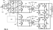
- FIG. 9 is a circuit diagram of a single-stage bidirectional power supply 100 according to an exemplary embodiment.
- the single-stage bidirectional converter 130 is split into two parts, each with a transformer 225-1, 225-2 separating a primary port 220-1, 220-2 and a secondary port 230-1, 230-2.
- both the primary-side switches 240-1 and 240-2 have a half-bridge arrangement. As such, there are only two switches S PH and S P21 in the primary-side switches 240-1 in the first part and only two witches S P12 and S P22 in the primary-side switches 240-2 in the second part.
- each of the respective secondary-side switches 250-1 and 250-2 is in a full-bridge configuration.
- the two sets of primary-side switches 240-1 and 240-2 are connected in parallel at the input.
- the two sets of secondary-side switches 250-1 and 250-2 may be connected in parallel or in series based on control of the relays R 1 , R 2 , and R 3 by the controller 150, similarly to the arrangement discussed with reference to FIG. 8 .
- the control scheme discussed with reference to FIGs. 3A and 3B is used for the configuration shown in FIG. 9 .
- FIG. 10 is a circuit diagram of a single-stage bidirectional power supply 100 according to an exemplary embodiment.
- the controller 150 is part of the configuration of FIG. 10 but is not shown.
- the split to two parts is directly following the EMI filter 205.
- both the line-frequency rectifier/inverter 120 and the bidirectional converter 130 are split into two parts.
- Each part of the bidirectional converter 130 includes a transformer 225-1, 225-2 separating a primary port 220-1, 220-2 and a secondary port 230-1, 230-2.
- the line-frequency rectifier/inverter 120 and primary-side and secondary-side switches 240-1, 240-2, 250-1, and 250-2 are all in a full-bridge configuration.
- Each part of the line-frequency rectifier/inverter 120 and associated primary port 220-1, 220-2 is in parallel with the other.
- the two sets of secondary-side switches 250-1 and 250-2 may be connected in parallel or in series based on control of the relays R 1 , R 2 , and R 3 by the controller 150, similarly to the arrangement discussed with reference to FIG. 8 .
- the control scheme discussed with reference to FIGs. 3A and 3B is used for the configuration shown in FIG. 10 with the DPWM 340 and DPWM 350 each controlling eight switches (i.e., both 240-1 and 240-2 or both 250-1 and 250-1) rather than four, as indicated in FIGs. 3A and 3B .
- FIGS. 11-14 illustrate different embodiments of a three-phase power supply 1000 that includes various embodiments of the line-frequency rectifier/inverter 120 and the bidirectional converter 130, along with the control scheme discussed with reference to FIGs. 3A and 3B .
- FIG. 11 is a block diagram of a three-phase power supply 1000 that implements the rectifier/inverter 120 and the bidirectional converter 130 for each phase according to one or more embodiments. As shown, the rectifier/inverter 120 and the bidirectional converter 130 of each phase is controlled by a separate controller 150 that implements the control discussed with reference to FIGs. 3A and 3B .
- the exemplary arrangement is not intended to limit the various ways that the control scheme discussed with reference to FIGs. 3A and 3B may be implemented.
- the control functionality may be combined into one controller 150 or split into two or more than three controllers 150 according to alternate embodiments.
- each line-frequency rectifier/inverter 120 and bidirectional converter 130 pair is connected to the phase-to-phase input terminals.
- Each line-frequency rectifier/inverter 120 and bidirectional converter 130 pair may be implemented according to any of the embodiments detailed with reference to FIGs. 2 and 6-10 .
- the voltages V TN , V SN , V RN associated with the different phases are phase-shifted by 120 degrees from each other.
- the ripple of the output DC voltages of the three phases (V DC,1 , V DC,2 , V DC,3 ) are also 120 degrees phase-shifted from each other.
- the ripple of the DC output voltage V DC is very small.
- FIG. 12 is a block diagram of a three-phase power supply 1000 that implements the line-frequency rectifier/inverter 120 and the bidirectional converter 130 for each phase according to one or more embodiments.
- the configuration shown in FIG. 12 differs from the configuration of FIG. 11 in that a separate EMI filter 205 is provided for each phase. This embodiment is further detailed in FIG. 13 .
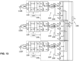
- FIG. 13 is a circuit diagram of the three-phase power supply 1000 shown in FIG. 12 .
- the exemplary embodiment of each line-frequency rectifier/inverter 120 and bidirectional converter 130 pair is similar to the embodiment shown in FIG. 2 .
- the relays R 1 , R 2 , and R 3 may be controlled by one or more of the controllers 150 or by a separate controller to connect the secondary port 230 of the three bidirectional converters 130 in a full-bridge or stacked half-bridge arrangement.
- the control of the relays R 1 , R 2 , and R 3 may be based on the value of the output DC voltage V DC , as discussed with reference to FIG. 8 .
- FIG. 14 is a block diagram of a three-phase power supply 1000 that implements the line-frequency rectifier/inverter 120 and the bidirectional converter 130 for each phase according to one or more embodiments.
- the embodiment shown in FIG. 14 differs from the embodiment shown in FIG. 12 in that each line-frequency rectifier/inverter 120 and bidirectional converter 130 pair is connected to the phase-neutral input terminals (rather than to the phase-to-phase input terminals).
- Another exemplary variation of Fig. 14 involves the three phases sharing a common EMI filter 205, as shown in FIG. 11 .
- a bidirectional power supply includes an alternating current (AC) port as a source in a first mode of operation and as a load in a second mode of operation and a line-frequency rectifier/inverter including a set of diodes to function as a rectifier to rectify an AC input from the AC port in the first mode of operation and a set of switches to function as an inverter to supply the AC port in the second mode of operation.
- a bidirectional resonant converter is coupled to a direct current (DC) port.
- the bidirectional resonant converter includes a primary port with primary-side switches and a secondary side port with secondary-side switches respectively arranged on a primary and secondary side of a transformer.
- a controller controls the primary-side switches and the secondary-side switches during a first control mode by controlling a switching frequency based on a determined value while setting a time delay between control of the primary-side switches and the secondary-side switches to be a predefined time delay.
- the controller controls the primary-side switches and the secondary-side switches during a second control mode by controlling the time delay between control of the primary-side switches and the secondary-side switches based on a determined value while setting the switching frequency to be a predefined switching frequency.
- the controller controls the set of switches at a fixed frequency based on a frequency of AC current at the AC port.
- An electromagnetic interference (EMI) filter is disposed between the AC port and the line-frequency rectifier/inverter.
- a capacitor is arranged between the line-frequency rectifier/inverter and the bidirectional resonant converter.
- a voltage V B across the capacitor is a rectified AC voltage.
- the controller applies the time delay from control of the primary-side switches to control of the secondary-side switches.
- the controller obtains an output voltage V DC at the DC port, the voltage V B across the capacitor, and an average input current of the bidirectional resonant converter i BR,avg to determine a control voltage V iea .
- the controller obtains the control voltage V iea directly from a current controller or from an adder arranged to add an output of the current controller and a mapped voltage obtained from a mapping of the output voltage V DC at the DC port, the voltage V B across the capacitor, a voltage VAC at the AC port, or a power output at the DC port to the mapped voltage.
- the controller provides the control voltage V iea to a first limiter that provides the time delay and a second limiter that provides the switching frequency and either the first limiter causes the time delay to be the predefined time delay or the second limiter causes the switching frequency to be the predefined switching frequency but not both.
- the controller applies the time delay from control of the secondary-side switches to control of the primary-side switches.
- the controller obtains a reference AC current i AC,ref or a reference AC voltage V AC,ref from a reference generator and the voltage V B across the capacitor to determine a control voltage V iea .
- the controller provides the control voltage V iea to a first limiter that provides the time delay and a second limiter that provides the switching frequency and either the first limiter causes the time delay to be the predefined time delay or the second limiter causes the switching frequency to be the predefined switching frequency but not both.
- the primary-side switches of the bidirectional resonant converter are arranged in a full-bridge or half-bridge configuration and the secondary-side switches of the bidirectional resonant converter are arranged in a full-bridge or a stacked half-bridge configuration.
- the secondary-side switches are arranged in the stacked half-bridge configuration and the secondary port includes relays to be controlled to maintain the stacked half-bridge configuration when an output voltage V DC at the DC port is above a threshold value and to convert to the full-bridge configuration when the output voltage V DC at the DC port is below a threshold value.
- the bidirectional resonant converter includes a second primary port with second primary-side switches and a second secondary side port with second secondary-side switches respectively arranged on a primary and secondary side of a second transformer.
- a second line-frequency rectifier/inverter is coupled to the second primary port.
- the power supply is a three-phase power supply such that the AC port includes three ports of different phases and each of the three ports is coupled to a pair of the line-frequency rectifier/inverter and the bidirectional resonant converter.
- a bidirectional resonant converter includes a primary port with primary-side switches and a secondary side port with secondary-side switches respectively arranged on a primary and secondary side of a transformer.
- a controller controls the primary-side switches and the secondary-side switches during a first control mode by controlling a switching frequency based on a determined value while setting a time delay between control of the primary-side switches and the secondary-side switches to be a predefined time delay.
- the controller controls the primary-side switches and the secondary-side switches during a second control mode by controlling the time delay between control of the primary-side switches and the secondary-side switches based on a determined value while setting the switching frequency to be a predefined switching frequency.
- the primary-side switches of the bidirectional resonant converter are arranged in a full-bridge or half-bridge configuration and the secondary-side switches of the bidirectional resonant converter are arranged in a full-bridge or a stacked half-bridge configuration and the secondary-side switches are arranged in the stacked half-bridge configuration.
- the secondary port includes relays to be controlled to maintain the stacked half-bridge configuration when an output voltage V DC at the secondary port is above a threshold value and to convert to the full-bridge configuration when the output voltage V DC is below a threshold value.
- the bidirectional resonant converter includes a second primary port with second primary-side switches and a second secondary side port with second secondary-side switches respectively arranged on a primary and secondary side of a second transformer.
- a method of manufacturing a bidirectional resonant converter includes coupling a line-frequency rectifier/inverter to an AC port.
- the line-frequency rectifier/inverter includes a set of diodes to function as a rectifier to rectify an AC input from the AC port in a first mode of operation and a set of switches to function as an inverter to supply the AC port in a second mode of operation.
- the method also includes coupling a bidirectional resonant converter to the line-frequency rectifier/inverter and to a direct current (DC) port.
- the bidirectional resonant converter and the line-frequency rectifier/inverter may be integrated on the same PCB or on different PCB according to actual needs.
- the AC input and the line-frequency rectifier/inverter may be disposed in a case
- the bidirectional resonant converter and the DC input may be disposed in another case, and two cases are connected to each other through external wires.
- the bidirectional resonant converter includes a primary port with primary-side switches and a secondary side port with secondary-side switches respectively arranged on a primary and secondary side of a transformer.
- a controller is configured to control the primary-side switches and the secondary-side switches during a first control mode by controlling a switching frequency based on a determined value while setting a time delay between control of the primary-side switches and the secondary-side switches to be a predefined time delay.
- the controller is also configured to control the primary-side switches and the secondary-side switches during a second control mode by controlling the time delay between control of the primary-side switches and the secondary-side switches based on a determined value while setting the switching frequency to be a predefined switching frequency.
Landscapes
- Engineering & Computer Science (AREA)
- Power Engineering (AREA)
- Dc-Dc Converters (AREA)
- Rectifiers (AREA)
- Ac-Ac Conversion (AREA)
- Physics & Mathematics (AREA)
- Electromagnetism (AREA)
Applications Claiming Priority (1)
| Application Number | Priority Date | Filing Date | Title |
|---|---|---|---|
| US18/311,651 US12531467B2 (en) | 2023-05-03 | 2023-05-03 | Single-stage bidirectional power supply |
Publications (1)
| Publication Number | Publication Date |
|---|---|
| EP4459853A1 true EP4459853A1 (de) | 2024-11-06 |
Family
ID=90482376
Family Applications (1)
| Application Number | Title | Priority Date | Filing Date |
|---|---|---|---|
| EP24166256.8A Pending EP4459853A1 (de) | 2023-05-03 | 2024-03-26 | Bidirektionale stromversorgung, bidirektionaler resonanzwandler und verfahren zur herstellung eines bidirektionalen resonanzwandlers |
Country Status (5)
| Country | Link |
|---|---|
| US (2) | US12531467B2 (de) |
| EP (1) | EP4459853A1 (de) |
| JP (1) | JP2024160938A (de) |
| CN (1) | CN118900051A (de) |
| TW (1) | TWI897321B (de) |
Families Citing this family (2)
| Publication number | Priority date | Publication date | Assignee | Title |
|---|---|---|---|---|
| WO2022229730A1 (en) * | 2021-04-29 | 2022-11-03 | Terna S.P.A. | Ac/dc converter, dc/ac converter and dc/dc converter and method of control of the converter |
| JP2022185478A (ja) * | 2021-06-02 | 2022-12-14 | 株式会社日立製作所 | 電力変換装置、電力変換システム、および、電力変換装置の制御方法 |
Citations (2)
| Publication number | Priority date | Publication date | Assignee | Title |
|---|---|---|---|---|
| US20210099096A1 (en) * | 2019-09-27 | 2021-04-01 | Infineon Technologies Austria Ag | Bi-directional LLC Converter |
| CN115995985A (zh) * | 2023-02-13 | 2023-04-21 | 重庆邮电大学 | 一种双向对称llc谐振变换器的控制方法 |
Family Cites Families (20)
| Publication number | Priority date | Publication date | Assignee | Title |
|---|---|---|---|---|
| US5283726A (en) | 1991-12-20 | 1994-02-01 | Wilkerson A W | AC line current controller utilizing line connected inductance and DC voltage component |
| EP1195877B1 (de) | 2000-10-06 | 2018-09-12 | ABB Schweiz AG | Stromrichtersystem mit durch einen Gleichspannungszwischenkreis verbundenen Stromrichtermodulen sowie Verfahren zum Betrieb |
| TWI239134B (en) | 2004-04-28 | 2005-09-01 | Wai Zheng Zhong | High-efficiency voltage-clamped DC/DC converter |
| US9048720B2 (en) | 2013-04-02 | 2015-06-02 | Raytheon Company | Bidirectional motor driver low voltage power supply (LVPS) |
| US9325252B2 (en) | 2014-01-13 | 2016-04-26 | Rockwell Automation Technologies, Inc. | Multilevel converter systems and sinusoidal pulse width modulation methods |
| US9490704B2 (en) | 2014-02-12 | 2016-11-08 | Delta Electronics, Inc. | System and methods for controlling secondary side switches in resonant power converters |
| GB2528894B (en) | 2014-08-01 | 2017-05-10 | Eisergy Ltd | Power factor correction stages in power conversion |
| CN107241021A (zh) * | 2017-08-03 | 2017-10-10 | 上海交通大学 | 一种三重移相控制下dab变换器全局优化闭环控制方法 |
| US11491883B2 (en) * | 2018-04-10 | 2022-11-08 | University Of Maryland, College Park | Vehicle on-board charger for bi-directional charging of low/high voltage batteries |
| CN109361318B (zh) * | 2018-09-19 | 2021-03-02 | 上海交通大学 | 基于dab的单级隔离型pfc变换器直接电流控制系统及控制方法 |
| US10693381B1 (en) * | 2018-11-30 | 2020-06-23 | Infineon Technologies Austria Ag | Startup mode for control of a resonant power converter |
| US11451139B2 (en) | 2019-01-22 | 2022-09-20 | Queen's University At Kingston | Three-phase single-stage soft-switching AC-DC converter with power factor correction |
| US11837962B2 (en) * | 2020-07-10 | 2023-12-05 | Uti Limited Partnership | Control system and method for dual active bridge DC/DC converters |
| US12046997B2 (en) | 2020-07-13 | 2024-07-23 | Delta Electronics, Inc. | Isolated resonant converter and control method thereof |
| TWI766314B (zh) | 2020-07-21 | 2022-06-01 | 茂達電子股份有限公司 | 具飛馳電容自動平衡機制的電源轉換器 |
| US11594973B2 (en) | 2020-08-04 | 2023-02-28 | Delta Electronics Inc. | Multiple-port bidirectional converter and control method thereof |
| WO2022190988A1 (ja) | 2021-03-12 | 2022-09-15 | パナソニックホールディングス株式会社 | 電力変換装置 |
| US20220321016A1 (en) | 2021-03-29 | 2022-10-06 | University Of Maryland, College Park | Multi-port power converters and power conversion systems, and methods for design and operation thereof |
| US11984815B2 (en) * | 2021-05-27 | 2024-05-14 | North Carolina State University | Modular isolated power electronics converter for HVAC/MVAC to LVDC power conversion |
| US11894776B2 (en) | 2021-10-28 | 2024-02-06 | Utah State University | Constant current to constant voltage dual active bridge LCL-transformer resonant DC-DC converter |
-
2023
- 2023-05-03 US US18/311,651 patent/US12531467B2/en active Active
-
2024
- 2024-03-26 EP EP24166256.8A patent/EP4459853A1/de active Pending
- 2024-03-27 JP JP2024052149A patent/JP2024160938A/ja active Pending
- 2024-03-28 TW TW113111606A patent/TWI897321B/zh active
- 2024-04-02 CN CN202410393602.1A patent/CN118900051A/zh active Pending
-
2025
- 2025-12-23 US US19/431,488 patent/US20260121510A1/en active Pending
Patent Citations (2)
| Publication number | Priority date | Publication date | Assignee | Title |
|---|---|---|---|---|
| US20210099096A1 (en) * | 2019-09-27 | 2021-04-01 | Infineon Technologies Austria Ag | Bi-directional LLC Converter |
| CN115995985A (zh) * | 2023-02-13 | 2023-04-21 | 重庆邮电大学 | 一种双向对称llc谐振变换器的控制方法 |
Non-Patent Citations (1)
| Title |
|---|
| MUKHERJEE SATYAKI ET AL: "A High Power Density Wide Range DC-DC Converter for Universal Electric Vehicle Charging", IEEE TRANSACTIONS ON POWER ELECTRONICS, INSTITUTE OF ELECTRICAL AND ELECTRONICS ENGINEERS, USA, vol. 38, no. 2, 24 October 2022 (2022-10-24), pages 1998 - 2012, XP011927443, ISSN: 0885-8993, [retrieved on 20221115], DOI: 10.1109/TPEL.2022.3217092 * |
Also Published As
| Publication number | Publication date |
|---|---|
| US12531467B2 (en) | 2026-01-20 |
| US20260121510A1 (en) | 2026-04-30 |
| TW202445967A (zh) | 2024-11-16 |
| CN118900051A (zh) | 2024-11-05 |
| JP2024160938A (ja) | 2024-11-15 |
| TWI897321B (zh) | 2025-09-11 |
| US20240372476A1 (en) | 2024-11-07 |
Similar Documents
| Publication | Publication Date | Title |
|---|---|---|
| US6310785B1 (en) | Zero voltage switching DC-DC converter | |
| TWI547076B (zh) | 低輸入電流諧波三相升壓整流器 | |
| US8693213B2 (en) | Resonant power factor correction converter | |
| CN102457193B (zh) | 具有单级转换器的电源供应器 | |
| EP4459853A1 (de) | Bidirektionale stromversorgung, bidirektionaler resonanzwandler und verfahren zur herstellung eines bidirektionalen resonanzwandlers | |
| US7633782B1 (en) | 100% duty-cycle buck-derived and 0% duty-cycle boost-derived power factor corrected (PFC) 3-phase Ac-Dc power converters | |
| US5734562A (en) | Power factor correction circuit | |
| US5790389A (en) | Consolidated soft-switching AC/DC converters | |
| CN102668352B (zh) | 带有功率因数校正的转换器 | |
| KR20190115364A (ko) | 단상 및 3상 겸용 충전기 | |
| Jang et al. | Bridgeless buck PFC rectifier | |
| CN111835208A (zh) | 一种具有pfc电路的开关电源 | |
| Duarte et al. | Single-stage high power factor step-up/step-down isolated AC/DC converter | |
| CN111404401A (zh) | 三相ac-dc交直流转换器、实现三相ac-dc交直流转换器的方法 | |
| JP5661818B2 (ja) | 混合型直流交流変換システムおよびその制御方法 | |
| JP2022006847A (ja) | 昇圧型電流共振dc-dcコンバータ | |
| WO2018148932A1 (en) | Dc to dc converter | |
| WO2023224008A1 (ja) | 多相llc共振コンバータ回路 | |
| US20250385621A1 (en) | Three-phase single-stage power supply | |
| Choi et al. | A new unity power factor telecom rectifier system by an active waveshaping technique | |
| Postiglione et al. | Single-stage PFC AC–DC converter based on serial-interleaved boost | |
| RU205720U1 (ru) | Резонансный конвертор напряжения | |
| EP4670266B1 (de) | Elektrischer wechselstrom-gleichstrom-schaltwandler | |
| EP4664739A1 (de) | Bidirektionale wechselstrom-gleichstrom-stromversorgung | |
| CN209963965U (zh) | Ac/dc变换电路 |
Legal Events
| Date | Code | Title | Description |
|---|---|---|---|
| PUAI | Public reference made under article 153(3) epc to a published international application that has entered the european phase |
Free format text: ORIGINAL CODE: 0009012 |
|
| STAA | Information on the status of an ep patent application or granted ep patent |
Free format text: STATUS: THE APPLICATION HAS BEEN PUBLISHED |
|
| AK | Designated contracting states |
Kind code of ref document: A1 Designated state(s): AL AT BE BG CH CY CZ DE DK EE ES FI FR GB GR HR HU IE IS IT LI LT LU LV MC ME MK MT NL NO PL PT RO RS SE SI SK SM TR |
|
| STAA | Information on the status of an ep patent application or granted ep patent |
Free format text: STATUS: REQUEST FOR EXAMINATION WAS MADE |
|
| 17P | Request for examination filed |
Effective date: 20250429 |