EP4459846A1 - Bürstenloser doppelt gespeister induktionsgenerator mit steuerwicklung und rotor - Google Patents
Bürstenloser doppelt gespeister induktionsgenerator mit steuerwicklung und rotor Download PDFInfo
- Publication number
- EP4459846A1 EP4459846A1 EP24460018.5A EP24460018A EP4459846A1 EP 4459846 A1 EP4459846 A1 EP 4459846A1 EP 24460018 A EP24460018 A EP 24460018A EP 4459846 A1 EP4459846 A1 EP 4459846A1
- Authority
- EP
- European Patent Office
- Prior art keywords
- winding
- phase
- stator
- power
- rotor
- Prior art date
- Legal status (The legal status is an assumption and is not a legal conclusion. Google has not performed a legal analysis and makes no representation as to the accuracy of the status listed.)
- Pending
Links
Images

Classifications
-
- H—ELECTRICITY
- H02—GENERATION; CONVERSION OR DISTRIBUTION OF ELECTRIC POWER
- H02K—DYNAMO-ELECTRIC MACHINES
- H02K17/00—Asynchronous induction motors; Asynchronous induction generators
- H02K17/42—Asynchronous induction generators
-
- H—ELECTRICITY
- H02—GENERATION; CONVERSION OR DISTRIBUTION OF ELECTRIC POWER
- H02K—DYNAMO-ELECTRIC MACHINES
- H02K3/00—Details of windings
- H02K3/04—Windings characterised by the conductor shape, form or construction, e.g. with bar conductors
- H02K3/28—Layout of windings or of connections between windings
-
- H—ELECTRICITY
- H02—GENERATION; CONVERSION OR DISTRIBUTION OF ELECTRIC POWER
- H02P—CONTROL OR REGULATION OF ELECTRIC MOTORS, ELECTRIC GENERATORS OR DYNAMO-ELECTRIC CONVERTERS; CONTROLLING TRANSFORMERS, REACTORS OR CHOKE COILS
- H02P9/00—Arrangements for controlling electric generators for the purpose of obtaining a desired output
- H02P9/007—Control circuits for doubly fed generators
-
- H—ELECTRICITY
- H02—GENERATION; CONVERSION OR DISTRIBUTION OF ELECTRIC POWER
- H02P—CONTROL OR REGULATION OF ELECTRIC MOTORS, ELECTRIC GENERATORS OR DYNAMO-ELECTRIC CONVERTERS; CONTROLLING TRANSFORMERS, REACTORS OR CHOKE COILS
- H02P9/00—Arrangements for controlling electric generators for the purpose of obtaining a desired output
- H02P9/42—Arrangements for controlling electric generators for the purpose of obtaining a desired output to obtain desired frequency without varying speed of the generator
-
- H—ELECTRICITY
- H02—GENERATION; CONVERSION OR DISTRIBUTION OF ELECTRIC POWER
- H02K—DYNAMO-ELECTRIC MACHINES
- H02K17/00—Asynchronous induction motors; Asynchronous induction generators
- H02K17/02—Asynchronous induction motors
- H02K17/16—Asynchronous induction motors having rotors with internally short-circuited windings, e.g. cage rotors
-
- H—ELECTRICITY
- H02—GENERATION; CONVERSION OR DISTRIBUTION OF ELECTRIC POWER
- H02K—DYNAMO-ELECTRIC MACHINES
- H02K2213/00—Specific aspects, not otherwise provided for and not covered by codes H02K2201/00 - H02K2211/00
- H02K2213/03—Machines characterised by numerical values, ranges, mathematical expressions or similar information
-
- Y—GENERAL TAGGING OF NEW TECHNOLOGICAL DEVELOPMENTS; GENERAL TAGGING OF CROSS-SECTIONAL TECHNOLOGIES SPANNING OVER SEVERAL SECTIONS OF THE IPC; TECHNICAL SUBJECTS COVERED BY FORMER USPC CROSS-REFERENCE ART COLLECTIONS [XRACs] AND DIGESTS
- Y02—TECHNOLOGIES OR APPLICATIONS FOR MITIGATION OR ADAPTATION AGAINST CLIMATE CHANGE
- Y02E—REDUCTION OF GREENHOUSE GAS [GHG] EMISSIONS, RELATED TO ENERGY GENERATION, TRANSMISSION OR DISTRIBUTION
- Y02E10/00—Energy generation through renewable energy sources
- Y02E10/70—Wind energy
- Y02E10/72—Wind turbines with rotation axis in wind direction
Definitions
- the invention relates to brushless doubly-fed induction generator - doubly-fed brushless induction with an external rotor and a multiphase control winding for use in a wind turbine.
- Wind power generation is a proven and widely used method for producing electricity without harmful carbon emissions. Turbines with capacities up to several megawatts are commonly used. Electromechanical converters such as classical synchronous generators, permanent magnet synchronous generators, and induction generators are used. An alternative to magnet-based generators are synchronous generators without magnets. Efficient and reliable electricity generation over a wide range of speed variations is sought due to the nature of wind turbine operation. Therefore, a popular solution in wind turbines is a doubly-fed induction generator, which can be successfully used in a wind turbine or other industrial solutions.
- Brushless doubly-fed induction generators with an internal rotor are known, e.g. in US 2014/0145541 A1 , WO2005/0460644 A1 ; US5083077A ; WO 2009/150464 and with an external rotor described e.g. in CN201045750Y ; CN1674415A , which consist of three main circuits: a stator with a three-phase power winding connected to the power grid, a movable rotor circuit with a three-phase short-circuited winding and a second independent stationary three-phase control circuit located on the stator. The three-phase stationary winding of the stator power winding is connected directly to the power grid.
- the second independent stationary three-phase stator control winding is supplied by a power electronic converter with bi-directional power flow, which adapts the required winding supply frequency to the actual rotor speed.
- the generator rotor which has a multiphase short-circuited winding, is a rotating element that magnetically couples the stationary power and control windings to the stator.
- the key advantage of the brushless doubly-fed induction generator is its ability to independently control active and reactive power on the three-phase power winding side of the stator through the five-phase control winding, which is also located on the stator.
- the second significant advantage is the ratio of power returned to the grid from the stator power winding to the power of the stator control winding. This ratio is typically 3:1, resulting in lower converter power requirements compared to other variable-speed generator solutions.
- the most significant advantage of a doubly-fed brushless induction generator is the ability to operate in a wide range of changes in the rotational speed of the machine shaft (typically from 0.7 to 1.3 synchronous speed) and suitable technical parameters of the quality of energy transferred to the grid. These functions are very beneficial due to maximising energy obtained from the wind, especially for high-power generators. Hence, solutions with even better parameters and construction, such as brushless generators, are being sought.
- the purpose of this invention was to provide a generator without disadvantages of the known generator.
- the goal was to provide generator with external rotor that could be connected to a wind turbine, since such generator enabling the blades to be mounted directly on the rotating element of the rotor.
- the described invention is based on the known structures of the double-fed induction generator presented above; however, it allows using a five-phase control winding placed on the internal stator in the invention's structure instead of the classic three-phase one.
- the control winding of the internal stator is powered by a dedicated five-phase power electronic converter.
- the generator's external shorted rotor is not directly powered.
- the current flow in the rotor results from the supply of the five-phase control winding from the converter and the three-phase power winding from the power grid.
- a doubly-fed brushless induction generator with a movable external rotor and an internal stator circuit with at least two windings is equipped with - comprising a fixed three-phase power winding S1 and a five-phase control winding.
- the three-phase power winding on the stator is connected directly to the three-phase power grid, while the five-phase control winding is supplied by a power electronic converter with bidirectional power flow.
- the five-phase stator control winding is powered by a five-phase power electronic converter with a constant number of phases in the three-phase stator power winding equal to three.
- the three-phase power winding is constructed, arranged such that it prevent magnetic coupling with the five-phase control winding - between three and five-phase control winding.
- three-phase control winding there is a coil span - so it uses a coil span equal to the number of slots per pole and phase of this winding.
- stator slots Qs with the three-phase power winding and the five-phase control winding must be - are divisible - are dividable by the natural number 3 and 5 without remainder - rest/change and are not equal to the rotor slots Qr in which the three-phase and five-phase control windings are placed.
- the generator comprising - is equipped with a fixed three-phase power winding on the internal stator -non-movable - immobile - immovable - stationary, a fixed - stationary five-phase control winding on the internal stator, a rotating - mobile/movable winding short-circuited - concrete in the outer rotor, and comprising a five-phase power electronic converter.
- the core of the internal stator is a stationary element - not movable - made of electrotechnical sheet packages embedded - that is placed-positioned in the generator's supporting structure.
- the outer rotor is a hub to which three wind turbine blades are directly mounted - in the number 3.
- 5-phase windings are used on the control side.
- the stator windings power and control windings
- the stator windings are doubly-layered with a coil span number corresponding to the number of slots per pole and phase. This enable to eliminate direct coupling of the windings.
- the use of a five-phase control winding in the internal stator instead of a three-phase winding increases the reliability of the generator and reduces service and inspection costs.
- the system can operate even if two phases of the stator control winding are damaged or if the converter branches are damaged.
- the invention enable to have low sensitivity to voltage disturbances on the stator power winding side. As a result, voltage disturbances on the stator side and the inability to continue operation in the event of failure of at least one of the branches of the converter supplying the control winding circuit have been eliminated.
- the generator with a five-phase control winding in the internal stator and a short-circuited winding in the external rotor is also characterised by better parameters of the quality of energy transferred to the grid. This quality of energy is due to the possibility of generating additional voltage harmonics on the side of the stator power winding to compensate for interference from the power grid or asymmetry of the machine's magnetic circuit.
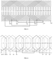
- Fig. 1 shows a diagram of the generator
- Fig. 2 shows a cross-section of the generator
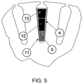
- Fig. 5 shows a method of placing a double-layer power winding S1 and a method of placing a single-layer control winding S2 in the slot of the generator stator.
- the doubly-fed induction generator has a cylindrical structure. It is composed - comprises - of the following structural elements: inner stator 1, outer rotor 2, generator shaft 3, fixed three-phase power S1 winding 4 - stationary three-phase winding 4 power S1 - on stator 1, fixed five-phase control winding 5 - S2 - on the stator 1 - control - steer winding, rotating winding 6 short-circuited in the outer rotor 2, integrated five-phase power electronic converter 7.
- the stator core 1 is a stationary element of electrotechnical sheet packages mounted on the stationary generator shaft.
- the type designation such as Qs is standardly, generally used, known and refers to the number of stator 1 slots located around the perimeter of the electrotechnical sheet stack.
- the number of slots Qs of stator 1 is a multiple of the number of phases, what means 3 and 5.
- the stationary - not movable - three-phase power S1 winding 4 is magnetically coupled to the control winding 5 - S2 through the movable, rotating short-circuit winding W1 of rotor 2. It is essential that the number of rotor slots Qr was different from the stator slots Qs. Additionally, the number of nurseries must be even.
- the short-circuited W1 winding 6 is placed in the outer rotor 2 and must have a number of poles equal to the sum of the number of pairs of poles of the control winding and the power winding - (p1 + p2)/2.
- a compact winding means that the beginnings and ends of the windings are permanently connected.
- Fig. 5 shows a view of one slot 11 of the internal stator, in which three layers of windings are placed: one two-layer three-phase power winding 4 S1, which is divided into the upper part of the power winding 13, the lower part of the stationary three-phase power S1 winding 4 12. In the remaining part of the slot, there is a single-layer, five-phase control winding 5.
- the three-phase power S1 winding 4 is distributed, arranged in such a way as to eliminate magnetic coupling between the three-phase power S1 winding 4 and the five-phase control winding 5 - S2, in the three-phase power S1 winding 4 an abbreviation of the coil span equal in value to the number of slots per pole and phase of this winding.
- the three-phase power S1 winding designed this way eliminates the possibility of magnetic coupling between it and the five-phase control winding S2. It also eliminate the influence of the third harmonic in the power S1 winding in the case of the configuration of the number of pole pairs of the power windings (one pair of poles) and the control winding (three pairs of poles).
- the number of slots Qs of stator 1 is 30, while the number of slots Qr of the rotor is 24.
- the S1, fixed three-phase power winding 4 is distributed evenly around the circumference of stator 1.
- a single phase of the power winding occupies 20 slots of the stator, 1 - 10 upper layers, and 10 middle layers of the slot, giving a coil shortcut of 5.
- the S2, five-phase control winding 5 is distributed evenly in all the lower layers of the stator slots 1.
- a single coil of each phase occupies 2 slots (beginning and end), and the entire single phase has 6 slots (evenly every 72 degrees).
- the beginning and end of the three-phase power S1 winding 4 of stator 1 and the five-phase control winding 5 - S2 of stator 1 are connected to a terminal board inside the nacelle.
- the three-phase power S1 winding 4 of the stator is connected to the power grid, while the five-phase control winding 5 - S2 of stator 1 is powered by the power electronics converter 7.
- the outer rotor 2 is the machine's rotating element. Its magnetic core is made of packages of electrotechnical sheets with a number of slots equal to Qr, in which a winding made of copper rods is placed.
- the ends and beginnings of all phases of the winding W1 of rotor 3 are permanently connected to each other, creating a short-circuited concentric winding W1. Due to the principle of operation of a brushless doubly-fed induction generator with a multiphase rotor winding W1 and control winding 5 - S2 of stator 1, the power electronic converter 7 supplies - energizes the control winding and delivers power to the rotor winding.
- the power electronic converter 7 is an adjustable voltage or current source supplying the five-phase stator control circuit.
- the power electronic converter 7 in the stator control winding S2 basically consists of two frequency converters, a machine one and a grid side one, connecting a three-phase electrical network with a constant voltage frequency of 50 Hz with a five-phase generator control circuit in which electric signals are characterised by variable frequency.
- the task of the converter is to power the rotor circuit by changing the voltage or current at the terminals of the stator control winding, taking into account changes in the frequency of electrical signals resulting from the principle of operation of the generator and the changing rotational speed of the generator shaft.
- a characteristic feature of the power electronic converter is four-quadrant operation, which requires the flow of electricity in the direction from the mains-supplied stator power winding through the short-circuit winding of the machine rotor to the stator control winding and in the opposite direction.
- the generator's condition is determined by the machine's operating point.
- the direction of the current in the i us power winding remains unchanged, i.e. from the generator to the power grid, while the direction of current flow in the i us control winding circuit.
- the current of the i ps power converter depends on the actual rotational speed of the external rotor generator relative to the magnetic field of stator 1.
- the invention is constructed similar as described in Example 1, except that the outer rotor is a hub to which 3 wind turbine blades are directly mounted.
- the hub housing is marked with the number 10, and an exemplary drawing of the mounting hook 8 and the turbine blade 9 is shown.
Landscapes
- Engineering & Computer Science (AREA)
- Power Engineering (AREA)
- Control Of Eletrric Generators (AREA)
Applications Claiming Priority (1)
| Application Number | Priority Date | Filing Date | Title |
|---|---|---|---|
| PL444544A PL444544A1 (pl) | 2023-04-24 | 2023-04-24 | Bezszczotkowy dwustronnie zasilany generator indukcyjny z uzwojeniem sterującym i zewnętrznym wirnikiem |
Publications (1)
| Publication Number | Publication Date |
|---|---|
| EP4459846A1 true EP4459846A1 (de) | 2024-11-06 |
Family
ID=91276881
Family Applications (1)
| Application Number | Title | Priority Date | Filing Date |
|---|---|---|---|
| EP24460018.5A Pending EP4459846A1 (de) | 2023-04-24 | 2024-04-19 | Bürstenloser doppelt gespeister induktionsgenerator mit steuerwicklung und rotor |
Country Status (2)
| Country | Link |
|---|---|
| EP (1) | EP4459846A1 (de) |
| PL (1) | PL444544A1 (de) |
Citations (6)
| Publication number | Priority date | Publication date | Assignee | Title |
|---|---|---|---|---|
| US5083077A (en) | 1990-07-31 | 1992-01-21 | The State Of Oregon Acting By And Through The State Board Of Higher Education On Behalf Of Oregon State University | Brushless doubly-fed generation system for vehicles |
| CN1674415A (zh) | 2004-03-25 | 2005-09-28 | 新疆金风科技股份有限公司 | 一种外转子双馈交流无刷异步电机 |
| CN201045750Y (zh) | 2007-05-15 | 2008-04-09 | 天津市新源电气科技有限公司 | 外转子无刷双馈发电机及其控制装置 |
| WO2009150464A1 (en) | 2008-06-13 | 2009-12-17 | Wind Technologies Limited | Power generators |
| US20140145541A1 (en) | 2011-07-15 | 2014-05-29 | Wind Technologies Limited | Brushless doubly fed machines |
| CN107134905A (zh) * | 2017-04-27 | 2017-09-05 | 南京航空航天大学 | 一种定子三相‑多相双绕组感应发电机系统 |
Family Cites Families (1)
| Publication number | Priority date | Publication date | Assignee | Title |
|---|---|---|---|---|
| PL441695A1 (pl) * | 2022-07-11 | 2023-07-31 | Politechnika Gdańska | Bezszczotkowy dwustronnie zasilany generator indukcyjny z uzwojeniem sterującym ze zwartym uzwojeniem wirnika |
-
2023
- 2023-04-24 PL PL444544A patent/PL444544A1/pl unknown
-
2024
- 2024-04-19 EP EP24460018.5A patent/EP4459846A1/de active Pending
Patent Citations (7)
| Publication number | Priority date | Publication date | Assignee | Title |
|---|---|---|---|---|
| US5083077A (en) | 1990-07-31 | 1992-01-21 | The State Of Oregon Acting By And Through The State Board Of Higher Education On Behalf Of Oregon State University | Brushless doubly-fed generation system for vehicles |
| CN1674415A (zh) | 2004-03-25 | 2005-09-28 | 新疆金风科技股份有限公司 | 一种外转子双馈交流无刷异步电机 |
| CN201045750Y (zh) | 2007-05-15 | 2008-04-09 | 天津市新源电气科技有限公司 | 外转子无刷双馈发电机及其控制装置 |
| WO2009150464A1 (en) | 2008-06-13 | 2009-12-17 | Wind Technologies Limited | Power generators |
| EP2301143B1 (de) * | 2008-06-13 | 2011-11-30 | Wind Technologies Limited | Stromgeneratoren |
| US20140145541A1 (en) | 2011-07-15 | 2014-05-29 | Wind Technologies Limited | Brushless doubly fed machines |
| CN107134905A (zh) * | 2017-04-27 | 2017-09-05 | 南京航空航天大学 | 一种定子三相‑多相双绕组感应发电机系统 |
Also Published As
| Publication number | Publication date |
|---|---|
| PL444544A1 (pl) | 2024-10-28 |
Similar Documents
| Publication | Publication Date | Title |
|---|---|---|
| US8193654B2 (en) | Variable speed power generator having two induction generators on a common shaft | |
| CA2658203C (en) | A hydroelectric turbine | |
| US8415817B2 (en) | Wind farm | |
| CN110971095B (zh) | 一种双定子风力发电机及发电系统 | |
| US7843078B2 (en) | Method and apparatus for generating power in a wind turbine | |
| EP2403111B1 (de) | Generator, Windturbine, Verfahren zur Montage eines Generators und Verwendung eines Generators in einer Windturbine | |
| Beik et al. | High-voltage hybrid generator and conversion system for wind turbine applications | |
| WO1996029774A1 (en) | Doubly-salient permanent-magnet machine | |
| CN101964575B (zh) | 双等极双段定转子磁阻发电机 | |
| Mirnikjoo et al. | Effect of rotor topology on the performance of counter-rotating double-sided flux switching permanent magnet generator | |
| Zhang | A brushless doubly fed machine with separated field and armature windings in dual stators | |
| US6930471B2 (en) | Hybrid synchronous/induction generator power plant | |
| EP4459846A1 (de) | Bürstenloser doppelt gespeister induktionsgenerator mit steuerwicklung und rotor | |
| Gwóźdź et al. | Generator with modulated magnetic flux for wind turbines | |
| CN101483371A (zh) | 调速恒频发电机 | |
| Mirnikjoo et al. | Design of an outer rotor flux switching permanent magnet generator for wind turbine | |
| CN110011505A (zh) | 双定子风力发电机 | |
| CN117240032A (zh) | 一种双转子电机及其工作方法 | |
| CN201138776Y (zh) | 调速恒频发电机 | |
| CN201478964U (zh) | 双等极双段定转子磁阻发电机 | |
| Udosen et al. | Non-Conventional, Non-Permanent Magnet Wind Generator Candidates. Wind 2022, 2, 429–450 | |
| CN109818442A (zh) | 一种交流无刷双馈电机 | |
| TA et al. | A CONCISE OVERVIEW OF GENERATORS FOR WIND ENERGY SYSTEM. | |
| CN116846173A (zh) | 一种双馈风力发电机及其发电系统 | |
| PL242467B1 (pl) | Dwustronnie zasilany generator indukcyjny o wielofazowym wzbudzeniu |
Legal Events
| Date | Code | Title | Description |
|---|---|---|---|
| PUAI | Public reference made under article 153(3) epc to a published international application that has entered the european phase |
Free format text: ORIGINAL CODE: 0009012 |
|
| STAA | Information on the status of an ep patent application or granted ep patent |
Free format text: STATUS: REQUEST FOR EXAMINATION WAS MADE |
|
| 17P | Request for examination filed |
Effective date: 20240515 |
|
| AK | Designated contracting states |
Kind code of ref document: A1 Designated state(s): AL AT BE BG CH CY CZ DE DK EE ES FI FR GB GR HR HU IE IS IT LI LT LU LV MC ME MK MT NL NO PL PT RO RS SE SI SK SM TR |