EP4459840A2 - Extrémité de réception de charge sans fil, dispositif terminal et procédé de charge sans fil - Google Patents
Extrémité de réception de charge sans fil, dispositif terminal et procédé de charge sans fil Download PDFInfo
- Publication number
- EP4459840A2 EP4459840A2 EP24201460.3A EP24201460A EP4459840A2 EP 4459840 A2 EP4459840 A2 EP 4459840A2 EP 24201460 A EP24201460 A EP 24201460A EP 4459840 A2 EP4459840 A2 EP 4459840A2
- Authority
- EP
- European Patent Office
- Prior art keywords
- charging
- voltage
- current
- battery
- wireless charging
- Prior art date
- Legal status (The legal status is an assumption and is not a legal conclusion. Google has not performed a legal analysis and makes no representation as to the accuracy of the status listed.)
- Pending
Links
Images


Classifications
-
- H—ELECTRICITY
- H02—GENERATION; CONVERSION OR DISTRIBUTION OF ELECTRIC POWER
- H02J—CIRCUIT ARRANGEMENTS OR SYSTEMS FOR SUPPLYING OR DISTRIBUTING ELECTRIC POWER; SYSTEMS FOR STORING ELECTRIC ENERGY
- H02J50/00—Circuit arrangements or systems for wireless supply or distribution of electric power
- H02J50/10—Circuit arrangements or systems for wireless supply or distribution of electric power using inductive coupling
- H02J50/12—Circuit arrangements or systems for wireless supply or distribution of electric power using inductive coupling of the resonant type
-
- H—ELECTRICITY
- H02—GENERATION; CONVERSION OR DISTRIBUTION OF ELECTRIC POWER
- H02J—CIRCUIT ARRANGEMENTS OR SYSTEMS FOR SUPPLYING OR DISTRIBUTING ELECTRIC POWER; SYSTEMS FOR STORING ELECTRIC ENERGY
- H02J50/00—Circuit arrangements or systems for wireless supply or distribution of electric power
- H02J50/10—Circuit arrangements or systems for wireless supply or distribution of electric power using inductive coupling
-
- H—ELECTRICITY
- H02—GENERATION; CONVERSION OR DISTRIBUTION OF ELECTRIC POWER
- H02J—CIRCUIT ARRANGEMENTS OR SYSTEMS FOR SUPPLYING OR DISTRIBUTING ELECTRIC POWER; SYSTEMS FOR STORING ELECTRIC ENERGY
- H02J50/00—Circuit arrangements or systems for wireless supply or distribution of electric power
- H02J50/80—Circuit arrangements or systems for wireless supply or distribution of electric power involving the exchange of data, concerning supply or distribution of electric power, between transmitting devices and receiving devices
-
- H—ELECTRICITY
- H02—GENERATION; CONVERSION OR DISTRIBUTION OF ELECTRIC POWER
- H02J—CIRCUIT ARRANGEMENTS OR SYSTEMS FOR SUPPLYING OR DISTRIBUTING ELECTRIC POWER; SYSTEMS FOR STORING ELECTRIC ENERGY
- H02J7/00—Circuit arrangements for charging or depolarising batteries or for supplying loads from batteries
- H02J7/02—Circuit arrangements for charging or depolarising batteries or for supplying loads from batteries for charging batteries from AC mains by converters
- H02J7/04—Regulation of charging current or voltage
- H02J7/06—Regulation of charging current or voltage using discharge tubes or semiconductor devices
-
- H02J7/60—
-
- H02J7/751—
-
- H02J7/975—
-
- H—ELECTRICITY
- H02—GENERATION; CONVERSION OR DISTRIBUTION OF ELECTRIC POWER
- H02J—CIRCUIT ARRANGEMENTS OR SYSTEMS FOR SUPPLYING OR DISTRIBUTING ELECTRIC POWER; SYSTEMS FOR STORING ELECTRIC ENERGY
- H02J1/00—Circuit arrangements for DC mains or DC distribution networks
- H02J1/10—Parallel operation of DC sources
- H02J1/102—Parallel operation of DC sources being switching converters
-
- H—ELECTRICITY
- H02—GENERATION; CONVERSION OR DISTRIBUTION OF ELECTRIC POWER
- H02J—CIRCUIT ARRANGEMENTS OR SYSTEMS FOR SUPPLYING OR DISTRIBUTING ELECTRIC POWER; SYSTEMS FOR STORING ELECTRIC ENERGY
- H02J2207/00—Indexing scheme relating to details of circuit arrangements for charging or depolarising batteries or for supplying loads from batteries
- H02J2207/40—Indexing scheme relating to details of circuit arrangements for charging or depolarising batteries or for supplying loads from batteries adapted for charging from various sources, e.g. AC, DC or multivoltage
Definitions
- the present disclosure generally relates to the technical field of charging, and more particularly, to a wireless charging receiving end, a terminal device and a method for wireless charging.
- a charged terminal device as a wireless charging receiving end, converts a wireless signal sent by a wireless charging transmitting end to obtain a corresponding charging signal provided an input signal of a power management chip to enable the power management chip to charge a battery of the terminal device.
- a wireless charging technology two solutions are required to improve charging power and efficiency: the first solution is to increase a current of a wireless charging signal under the condition of keeping a voltage constant, thereby increasing the power; and the second solution is to increase an input voltage under the condition of keeping a current constant, thereby increasing the power.
- the present disclosure provides a wireless charging receiving end, a terminal device and a method for wireless charging.
- a wireless charging receiving end which may include:
- a maximum input voltage allowed by the wireless charging management chip in the wireless charging receiving end is higher than a maximum input voltage allowed by a power management chip in the related art, so that an input voltage of the wireless charging management chip may be increased to improve charging power and charging efficiency, thus user experiences are improved.
- the terminal device may be charged quickly without any additional wired charging interface, so that the terminal device has better performance in terms of water resistance and safety.
- the wireless charging management chip may include multiple Metal-Oxide-Semiconductor Field-Effect Transistors (MOSFETs).
- MOSFETs Metal-Oxide-Semiconductor Field-Effect Transistors
- the energy receiver may include a receiving end coil and a receiving end capacitor; and the receiving end coil may be coupled to the receiving end processor through the receiving end capacitor, and may be configured to generate magnetic induction with an energy transmitter of a wireless charging transmitting end to send and receive the wireless signals.
- the receiving end processor and the wireless charging management chip may be coupled to a terminal device processor; and the receiving end processor may be configured to convert the alternating current into the direct current, demodulate the wireless signal received from the energy receiver and modulate the wireless signal sent by the wireless charging management chip through the terminal device processor.
- the wireless charging receiving end may further include:
- the wireless charging receiving end may further include a wireless charging switch and a wired charging management chip;
- the receiving end processor may include:
- a terminal device which may include:
- a method for wireless charging which may include that:
- the operation that the battery is controlled to be charged may include that:
- the operation that the target charging current of the battery is determined according to the present battery voltage and the battery is charged according to the target charging voltage and the target charging current may include that:
- the method may further include that:
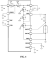
- Fig. 1 is a block diagram of a wireless charging system, according to an exemplary embodiment.
- the system may include a wireless charging transmitting end 2, a power supply 5 and a wireless charging receiving end 1.
- the power supply 5 is coupled to the wireless charging transmitting end 2.
- the wireless charging transmitting end 2 may include an energy transmitter 21, a charger 22, a transmitting end processor 23 and a controller 24.
- the transmitting end processor 23 is coupled to the energy transmitter 21, the charger 22 and the controller 24.
- the energy transmitter 21 may include a transmitting end coil 211 and a transmitting end capacitor 212.
- the transmitting end processor 23 is coupled to the transmitting end coil 211 through the transmitting end capacitor 212.
- the transmitting end processor 23 may include a full-bridge inverter circuit or a half-bridge inverter circuit, and the full-bridge inverter circuit or the half-bridge inverter circuit may be configured to convert a direct current into an alternating current.
- the controller 24 may be configured to control the full-bridge inverter circuit or the half-bridge inverter circuit, and may further be configured to modulate a wirelessly transmitted signal and demodulate an Amplitude Shift Keying (ASK) signal coupled in by the transmitting end coil 211.
- the transmitting end coil 211 may be configured to generate magnetic induction with a receiving end coil 111 in the wireless charging receiving end 1 to send and receive wireless signals.
- the wireless charging receiving end 1 may include an energy receiver 11, a receiving end processor 12 and a wireless charging management chip 13.
- the energy receiver 11 may include the receiving end coil 111 and a receiving end capacitor 112.
- the receiving end coil 111 may be coupled to the receiving end processor 12 through the receiving end capacitor 112, and may be configured to generate magnetic induction with the energy transmitter 21 (specifically the transmitting end coil 211) of the wireless charging transmitting end 2 to send and receive the wireless signals.
- the receiving end processor 12 is coupled to the energy receiver 11 and the wireless charging management chip 13, and may be configured to convert the alternating current into the direct current and modulate and demodulate the wireless signals.
- the receiving end processor 12 may include a rectification circuit 121, a modulation and demodulation circuit 122 and a control circuit 123.
- the rectification circuit 121 may be configured to convert the alternating current into the direct current.
- the modulation and demodulation circuit 122 may be configured to modulate and demodulate the wireless signals.
- the control circuit 123 is coupled to the rectification circuit 121 and the modulation and demodulation circuit 122, and may be configured to control operation of the rectification circuit 121 and the modulation and demodulation circuit 122.
- the wireless charging management chip 13 may be coupled to a battery 3, and may be configured to control charging of the battery 3.
- the wireless charging management chip 13 may include multiple MOSFETs (also referred to as MOS transistors) 131.
- MOSFETs also referred to as MOS transistors
- the wireless charging management chip 13 is a 3-level charger, herein the 3-level charger includes five MOS transistors 131.
- the wireless charging management chip 13 may further be electrically coupled to a terminal device system to supply power to the system.
- a maximum input voltage allowed by the wireless charging management chip in the wireless charging receiving end is higher than a maximum input voltage allowed by a power management chip in the related art, so that an input voltage of the wireless charging management chip may be increased to improve charging power and charging efficiency, thus user experiences are improved.
- a terminal device may be charged quickly without any additional wired charging interface, so that the terminal device has better performance in terms of water resistance and safety.
- Fig. 5 is a block diagram of a wireless charging system, according to another exemplary embodiment.
- the receiving end processor 12 and the wireless charging management chip 13 may be coupled to a terminal device processor 4.
- the receiving end processor 12 may be configured to convert the alternating current into the direct current, demodulate the wireless signal received from the energy receiver 11 and modulate the wireless signal sent by the wireless charging management chip 13 through the terminal device processor 4.
- Fig. 6 is a block diagram of a wireless charging system, according to another exemplary embodiment.
- the wireless charging receiving end 1 may further include a temperature acquisition element 14 (for example, a chip thermistor and an infrared temperature sensor) configured to acquire a terminal device temperature.
- the terminal device temperature may be a temperature of the battery 3, and may also be a temperature of the terminal device.
- the wireless charging management chip 13 is coupled to the temperature acquisition element 14, and may be configured to, when the terminal device temperature acquired by the temperature acquisition element 14 is greater than a preset temperature threshold value, decrease a present charging current and charge the battery 3 according to the decreased current.
- overheat protection of the battery may be implemented, the battery and a rear shell of the terminal device may be prevented from excessively high temperatures, damage to service life of the battery is avoided, the overall temperature of the terminal device is also reduced, the charging efficiency, the degree of charging freedom and the charging speed are balanced and ensured, and the user experience is improved.
- the preset temperature threshold value may be a value set by a user and may also be a default empirical value (for example, 40 degrees) and there are no specific limits made in the present disclosure.
- the wireless charging receiving end 1 may further include a charging control switch 15 and a wired charging management chip 16.
- the charging control switch 15 is coupled to the receiving end processor 12 and the wireless charging management chip 13, while the other end is coupled to the wired charging management chip 16.
- the charging control switch 15 may be a single-pole single-throw switch, a relay, an MOSFET (the charging control switch 15 shown in Fig. 7 is an MOSFET) and the like.
- wired charging management chip 16 One end of the wired charging management chip 16 is coupled to the wireless charging management chip 13, while the other end is coupled to the battery 3, and a wired charging interface 161 is formed in the wired charging management chip 16. Moreover, the wired charging management chip 16 may be configured to, when the charging control switch 15 is turned on or when the charging control switch 15 is turned off and the wired charging interface 161 is occupied, control charging of the battery 3.
- the wireless charging management chip 13 may be configured to, when the charging control switch 15 is turned on or when the charging control switch 15 is turned off and the wired charging interface 161 is not occupied, control the battery 3 to be wirelessly charged. That is, when the charging control switch 15 is turned on, the wireless charging management chip 13 and the wired charging management chip 16 simultaneously control the battery 3 to be wirelessly charged; when the charging control switch 15 is turned off and the wired charging interface 161 is occupied, the wired charging management chip 16 controls the battery to be wiredly charged, and the wireless charging management chip 13 does not work; and when the charging control switch 15 is turned off and the wired charging interface 161 is not occupied, the wireless charging management chip 13 controls the battery 3 to be wirelessly charged, and the wired charging management chip 16 does not work.
- the wired charging interface 161 may be a Universal Serial Bus (USB) interface, a Type-C interface and the like.
- USB Universal Serial Bus
- the wireless charging receiving end 1 may be arranged outside the terminal device, and when charging is required, the terminal device, after being mounted on the wireless charging terminal device 1, may be placed on the wireless charging transmitting end 2 for charging. This undoubtedly increases complexity in charging of the terminal device.
- the wireless charging receiving end 1 may be arranged in the terminal device. Then, when charging is required, the terminal device may directly be placed on the wireless charging transmitting end 2 for convenient and quick charging.
- the wireless charging system may further include a micro switch 6.
- the micro switch 6 may be arranged at a position, forming charging contact with the terminal device, on the wireless charging receiving end 1, and moreover, the wireless charging transmitting end 2 is coupled to the power supply 5 through the micro switch 6.
- the terminal device when being placed on the wireless charging receiving end 1, contacts with the micro switch 6, and then the micro switch 6 is triggered to be turned on to switch on the power supply 5 to start charging; and when the terminal device leaves the wireless charging transmitting end 2, the micro switch 6 is turned off to switch off the power supply 5 to stop charging.
- the present disclosure also provides a terminal device, which may include a battery 3, a terminal device processor 4 and the abovementioned wireless charging receiving end 1.
- Fig. 9 is a flow chart showing a method for wireless charging, according to an exemplary embodiment. As shown in Fig. 9 , the method for wireless charging may include the following operations.
- the alternating current power signal is converted into a direct current.
- a battery is controlled to be charged using the direct current.
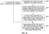
- Operation 903 may include Operation 9031 to Operation 9035 as follows.
- the information about voltage and current capabilities may include fixed Power Data Object (PDO) information and Augmented Power Data Object (APDO) information.
- PDO Power Data Object
- APDO Augmented Power Data Object
- the fixed PDO information may be 5V/3A, 9V/2A, 12V/1.5A and the like.
- the APDO information may represent programmable voltage and current information, for example, 3-5.9V/3A.
- a wireless charging management chip may acquire the information about voltage and current capabilities through the charger in a wireless charging transmitting end. Specifically, in an implementation mode, after the wireless charging transmitting end establishes a connection with a wireless charging receiving end, the charger may send its own information about voltage and current capabilities to the wireless charging receiving end, and the wireless charging receiving end receives the information about voltage and current capabilities of the charger. In such a manner, the wireless charging management chip acquires the information about voltage and current capabilities of the charger.
- the wireless charging receiving end after the wireless charging transmitting end establishes the connection with the wireless charging receiving end, the wireless charging receiving end sends a request message requesting for acquisition of the information about voltage and current capabilities of the charger to the charger in the wireless charging transmitting end, the charger, after receiving the request message, sends its own information about voltage and current capabilities to the wireless charging receiving end, and the wireless charging receiving end receives the information about voltage and current capabilities of the charger.
- the wireless charging management chip acquires the information about voltage and current capabilities of the charger.
- an input voltage threshold value of a wireless charging management chip is determined according to the information about voltage and current capabilities of the charger.
- a voltage value corresponding to a voltage range to which the input voltage threshold value belongs is determined as a target charging voltage of the battery.
- the input voltage threshold value Vrect of the wireless charging management chip may be determined accordingly, and then the voltage value corresponding to the voltage range to which the input voltage threshold value belongs may be determined as the target charging voltage of the battery. Moreover, the greater a lower limit value of the voltage range is, the smaller the voltage value corresponding to the voltage range is.
- the target charging voltage may be determined through prestored correspndences between voltage ranges and voltage values.
- the voltage range to which the input voltage threshold value Vrect belongs may be determined at first, then the voltage value corresponding to the voltage range to which the input voltage threshold value Vrect belongs is determined through the prestored correspondences between voltage ranges and voltage values, and the corresponding voltage value is determined as the target charging voltage of the battery.
- the target charging voltage may be determined in the following manner: when 5 V ⁇ Vrect ⁇ 10 V , the corresponding voltage value is a difference between the input voltage threshold value Vrect and a preset voltage value; when 10 V ⁇ Vrect ⁇ 15 V , the corresponding voltage value is a difference between Vrect/2 and the preset voltage value; when 15 V ⁇ Vrect ⁇ 20 V , the corresponding voltage value is a difference between Vrect/3 and the preset voltage value; and when Vrect ⁇ 20 V , the corresponding voltage value is a difference between Vrect/N and the preset voltage value, the preset voltage value being greater than 0 and less than Vrect/N and N being an integer more than or equal to 4.
- the preset voltage value may be a value set by a user and may also be a default empirical value and there are no specific limits made in the present disclosure.
- a target charging current of the battery is determined according to the present battery voltage, and the battery is charged according to the target charging voltage and the target charging current.
- Operation 9035 may include Operation 90351 to Operation 90359 as follows.
- the present battery voltage of the terminal device after the present battery voltage of the terminal device is acquired through Operation 9032, it may be determined at first whether it is more than or equal to the first preset voltage threshold value (for example, 2.5V) or not.
- the present battery voltage is more than or equal to the first preset voltage threshold value
- it may be determined whether the present battery voltage is less than a second preset voltage threshold value (for example, 4.4V), namely Operation 90352 is executed.
- a second preset voltage threshold value for example, 4.4V
- a trickle charging stage When the present battery voltage is less than the first preset voltage threshold value, a trickle charging stage may be entered, and in such case, a charging current value (for example, 45mA) corresponding to the trickle charging stage may be determined as the target charging current and then trickle charging is performed on the battery according to the target charging current and the target charging voltage determined in Operation 9034, namely Operation 90359 is executed.
- a charging current value for example, 45mA
- the first preset voltage threshold value is less than the second preset voltage threshold value
- all the first preset voltage threshold value, the second preset voltage threshold value and the charging current value corresponding to the trickle charging stage may be values set by the user and may also be default empirical values and there are no specific limits made in the present disclosure.
- a constant current charging stage may be entered, and in such case, the target charging current of the battery may be determined according to the present battery voltage and constant current charging is performed on the battery according to the target charging current and the target charging voltage determined in Operation 9034, namely Operation 90353 is executed.
- a present charging current may be decreased to obtain a new target charging current and, when the new target charging current is more than or equal to a preset charging current threshold value, constant current charging is performed on the battery according to the new target charging current and the target charging voltage determined in Operation 9034, namely Operation 90355 to Operation 90357 are executed.
- the target charging current of the battery is determined according to the present battery voltage, and constant current charging is performed on the battery according to the target charging voltage and the target charging current.
- a constant current charging process may include a pre-charging stage, a first constant current charging stage and a second constant current charging stage, specifically as follows.
- the third current may be set according to a battery cell specification.
- the second current is greater than the first current
- the third current is greater than the second current
- the first current and the second current may be values set by the user and may also be default empirical values and there are no specific limits made in the present disclosure.
- the present charging current may be decreased to obtain the new target charging current; when the new target charging current is more than or equal to the preset charging current threshold value (for example, 1 A), the constant current charging is performed on the battery according to the new target charging current and the target charging voltage determined in Operation 9034, namely Operation 90355 to 90357 are executed; and then, Operation 90354 is re-executed until the new target charging current is less than the preset charging current threshold value.
- the preset charging current threshold value for example, 1 A
- the preset charging current threshold value may be a value set by the user and may also be a default empirical value and there are no specific limits made in the present disclosure.
- a present charging current is decreased to obtain a new target charging current.
- the present charging current may be decreased by a preset current threshold value.
- the preset current threshold value may be a value set by the user and may also be a default empirical value and there are no specific limits made in the present disclosure.
- the present charging current may be decreased by a preset proportion (for example, 25%).
- the preset proportion may be a value set by the user and may also be a default empirical value and there are no specific limits made in the present disclosure.
- constant current charging may be performed on the battery according to the new target charging current and the target charging voltage determined in Operation 9034, namely Operation 90357 is executed.
- constant current charging may be stopped, and a constant voltage charging stage is entered; and in such case, constant voltage charging may be performed on the battery according to the new target charging current and the target charging voltage determined in Operation 9034, namely Operation 90358 is executed.
- charging in a constant voltage charging process, charging is performed in a manner of keeping the charging voltage substantially constant and gradually decreasing the charging current, and when the charging current is less than a preset charging stopping current (for example, 200 mA), charging may be stopped.
- a preset charging stopping current for example, 200 mA
- the preset charging stopping current may be a value set by the user and may also be a default empirical value and there are no specific limits made in the present disclosure.
- a charging current value corresponding to a trickle charging stage is determined as the target charging current of the battery, and trickle charging is performed on the battery according to the target charging voltage and the target charging current.
- different target charging currents IBAT may be set in the following manner.
- the target charging current IBAT is set to be 45mA.
- the target charging current IBAT is set to be 150mA.
- the target charging current IBAT is set to be 1 A.
- the target charging current IBAT may be set (for example, 1C and 1.5C) according to the battery cell specification.
- a third progressive charging stage when the VBAT reaches 4.4 V for the first time, the target charging current IBAT is decreased by 25%, and the second constant current charging stage is continued; when the VBAT reaches 4.4 V for the second time, the target charging current IBAT is continued to be decreased by 25%, and the second constant current charging stage is continued; and when the target charging current IBAT ⁇ 1 A, the third progressive charging stage is stopped, and constant voltage charging is started.
- Operation 9032 may be executed before Operation 9031, may also be executed after Operation 9031 and may further be executed concurrently with Operation 9031 and there are no specific limits made in the present disclosure.
- wireless charging authorization and authentication may be performed at first before Operation 9031.
- the method may further include Operation 9036 to Operation 9038 as follows.
- the battery is charged according to a preset voltage and a preset current.
- the preset voltage is 5 V
- the preset current is 1 A.
- both the preset voltage and the preset current may be values set by the user and may also be default empirical values and there are no specific limits made in the present disclosure.
- the wireless charging transmitting end detects a type of the charger, the type of the charger being an ordinary Dedicated Charging Port (DCP) charger, a QC2.0 charger, a QC3.0 charger, a QC4.0 charger, a PD charger and the like; and then, when the wireless charging transmitting end establishes the connection with the wireless charging receiving end (for example, after the terminal device with a built-in wireless charging receiving end is placed on the wireless charging transmitting end), the terminal device interacts with the wireless charging transmitting end using a protocol of a QI specification (for example, a Baseline Power Profile (BPP) protocol and an Extended Power Profile (EPP) protocol).
- DCP Dedicated Charging Port
- BPP Baseline Power Profile
- EPP Extended Power Profile
- the method may further include the following operations: when it is detected that a charging control switch is turned off and a wired charging interface is occupied, the battery is controlled to be wiredly charged under control of a wired charging management chip; when it is detected that the charging control switch is turned off and the wired charging interface is not occupied, the battery is controlled to be wirelessly charged under control of the wireless charging management chip; and when it is detected that the charging control switch is turned on, the battery is controlled to be wirelessly charged under control of the wireless charging management chip and the wired charging management chip.
- a wireless charging receiving end characterized in that, the wireless charging receiving end comprises:
- Clause 2 The wireless charging receiving end of clause 1, further comprising a charging control switch and a wired charging management chip,
- Clause 3 The wireless charging receiving end of clause 1, wherein the wireless charging management chip comprises multiple Metal-Oxide-Semiconductor Field-Effect Transistors (MOSFETs).
- MOSFETs Metal-Oxide-Semiconductor Field-Effect Transistors
- Clause 4 The wireless charging receiving end of clause 1, wherein the wireless charging receiving end further comprises: a temperature acquisition element, configured to acquire a temperature of the terminal device, wherein the wireless charging management chip is coupled to the temperature acquisition element, and is configured to, when the temperature acquired by the temperature acquisition element is greater than a preset temperature threshold value, decrease a present charging current and charge the battery according to the decreased present charging current.
- a temperature acquisition element configured to acquire a temperature of the terminal device
- the wireless charging management chip is coupled to the temperature acquisition element, and is configured to, when the temperature acquired by the temperature acquisition element is greater than a preset temperature threshold value, decrease a present charging current and charge the battery according to the decreased present charging current.
- Clause 5 The wireless charging receiving end of clause 1, wherein the energy receiver comprises a receiving end coil and a receiving end capacitor, wherein the receiving end coil is coupled to the receiving end processor through the receiving end capacitor, and is configured to send and receive wireless signals by generating magnetic induction with an energy transmitter of a wireless charging transmitting end.
- Clause 6 The wireless charging receiving end of clause 1, wherein the receiving end processor and the wireless charging management chip are coupled to a terminal device processor, wherein the receiving end processor is configured to convert the alternating current into the direct current, demodulate a wireless signal received from the energy receiver and modulate a wireless signal sent by the wireless charging management chip through the terminal device processor.
- Clause 7 The wireless charging receiving end of any one of clauses 1-6, wherein the receiving end processor comprises:
- a terminal device comprising:
- Clause 9 A method for wireless charging, characterized in that, the method comprises:
- Clause 10 The method of clause 9, wherein controlling the battery to be charged using the direct current comprises:
- Clause 11 The method of clause 10, wherein determining the target charging current of the battery according to the present battery voltage and charging the battery according to the target charging voltage and the target charging current comprises:
Landscapes
- Engineering & Computer Science (AREA)
- Power Engineering (AREA)
- Computer Networks & Wireless Communication (AREA)
- Charge And Discharge Circuits For Batteries Or The Like (AREA)
Applications Claiming Priority (2)
| Application Number | Priority Date | Filing Date | Title |
|---|---|---|---|
| CN201910099722.XA CN111509822B (zh) | 2019-01-31 | 2019-01-31 | 无线充电接收端、终端及无线充电方法 |
| EP19204658.9A EP3691076A1 (fr) | 2019-01-31 | 2019-10-22 | Extrémité de réception de chargement sans fil, dispositif terminal et procédé de chargement sans fil |
Related Parent Applications (1)
| Application Number | Title | Priority Date | Filing Date |
|---|---|---|---|
| EP19204658.9A Division EP3691076A1 (fr) | 2019-01-31 | 2019-10-22 | Extrémité de réception de chargement sans fil, dispositif terminal et procédé de chargement sans fil |
Publications (2)
| Publication Number | Publication Date |
|---|---|
| EP4459840A2 true EP4459840A2 (fr) | 2024-11-06 |
| EP4459840A3 EP4459840A3 (fr) | 2025-01-15 |
Family
ID=68342535
Family Applications (2)
| Application Number | Title | Priority Date | Filing Date |
|---|---|---|---|
| EP19204658.9A Withdrawn EP3691076A1 (fr) | 2019-01-31 | 2019-10-22 | Extrémité de réception de chargement sans fil, dispositif terminal et procédé de chargement sans fil |
| EP24201460.3A Pending EP4459840A3 (fr) | 2019-01-31 | 2019-10-22 | Extrémité de réception de charge sans fil, dispositif terminal et procédé de charge sans fil |
Family Applications Before (1)
| Application Number | Title | Priority Date | Filing Date |
|---|---|---|---|
| EP19204658.9A Withdrawn EP3691076A1 (fr) | 2019-01-31 | 2019-10-22 | Extrémité de réception de chargement sans fil, dispositif terminal et procédé de chargement sans fil |
Country Status (3)
| Country | Link |
|---|---|
| US (1) | US11289938B2 (fr) |
| EP (2) | EP3691076A1 (fr) |
| CN (1) | CN111509822B (fr) |
Families Citing this family (10)
| Publication number | Priority date | Publication date | Assignee | Title |
|---|---|---|---|---|
| CN112109567B (zh) * | 2020-08-18 | 2022-04-22 | 上海都都亮科技有限公司 | 一种充电方法、充电电路和充电设备 |
| WO2022041018A1 (fr) * | 2020-08-26 | 2022-03-03 | 华为技术有限公司 | Circuit de réception de charge sans fil, dispositif terminal et système de charge sans fil |
| CN112152955B (zh) * | 2020-09-24 | 2022-03-04 | 华润微集成电路(无锡)有限公司 | 基于无线充电系统实现fsk解码的方法 |
| CN114552683B (zh) * | 2020-11-24 | 2024-09-03 | 北京小米移动软件有限公司 | 检波电路、无线充电装置、终端设备、控制方法及装置 |
| CN112987951A (zh) * | 2021-03-23 | 2021-06-18 | 嘉兴技领信息技术有限公司 | 一种带无线充电功能的鼠标及其充电方法 |
| CN115882093A (zh) * | 2021-09-29 | 2023-03-31 | 北京小米移动软件有限公司 | 一种可无线充电的电池及其充电方法 |
| CN114050627A (zh) * | 2021-11-26 | 2022-02-15 | 努比亚技术有限公司 | 一种无线充电分离控制方法、设备及计算机可读存储介质 |
| CN114678924B (zh) * | 2022-03-15 | 2025-08-15 | 国网浙江省电力有限公司杭州供电公司 | 适应偏移工况的无线充电分阶段恒流恒压输出控制方法 |
| US12099389B2 (en) * | 2022-05-10 | 2024-09-24 | Apple Inc. | Systems and methods for thermal management using a mixed topology switching regulator |
| CN114915043B (zh) * | 2022-06-21 | 2025-12-05 | 珠海格力电器股份有限公司 | 感应加热器件、其控制方法以及感应加热设备 |
Family Cites Families (14)
| Publication number | Priority date | Publication date | Assignee | Title |
|---|---|---|---|---|
| US20060103355A1 (en) | 2004-11-16 | 2006-05-18 | Joseph Patino | Method and system for selectively charging a battery |
| JP2008193783A (ja) * | 2007-02-02 | 2008-08-21 | Nec Corp | 充電制御方法、携帯端末および充電制御システム |
| JP4725664B2 (ja) * | 2008-06-25 | 2011-07-13 | セイコーエプソン株式会社 | 送電制御装置、送電装置、受電制御装置、受電装置、電子機器、送電制御方法、及び受電制御方法 |
| US9287039B2 (en) | 2012-07-09 | 2016-03-15 | Lg Electronics Inc. | Wireless power transfer method, apparatus and system for low and medium power |
| KR102158288B1 (ko) * | 2012-07-09 | 2020-09-21 | 삼성전자주식회사 | 배터리를 충전하기 위한 방법 및 그 전자 장치 |
| US9431848B2 (en) * | 2012-12-06 | 2016-08-30 | Samsung Electronics Co., Ltd | Method and apparatus for protecting wireless power receiver from excessive charging temperature |
| JP2016181953A (ja) * | 2015-03-23 | 2016-10-13 | ルネサスエレクトロニクス株式会社 | ワイヤレス給電システム、送電装置及び受電装置 |
| JP6737636B2 (ja) * | 2016-05-27 | 2020-08-12 | ローム株式会社 | ワイヤレス受電装置およびその制御方法、受電制御回路、電子機器 |
| CN107482710B (zh) | 2017-07-31 | 2019-12-27 | 北京小米移动软件有限公司 | 无线充电方法及终端 |
| CN108767909B (zh) | 2018-03-30 | 2022-05-10 | 超威电源集团有限公司 | 一种标准的充电曲线及充电方法 |
| CN108879841B (zh) * | 2018-06-28 | 2020-10-16 | 努比亚技术有限公司 | 一种并行充电电路和移动终端 |
| CN108767957B (zh) * | 2018-07-27 | 2024-05-31 | 天宝电子(惠州)有限公司 | 一种交流输入无线充电装置、系统及方法 |
| CN109217487B (zh) | 2018-09-03 | 2020-04-10 | Oppo广东移动通信有限公司 | 充电电路及电子设备 |
| CN209217778U (zh) * | 2019-01-31 | 2019-08-06 | 北京小米移动软件有限公司 | 无线充电接收端、无线充电系统及终端 |
-
2019
- 2019-01-31 CN CN201910099722.XA patent/CN111509822B/zh active Active
- 2019-09-30 US US16/587,632 patent/US11289938B2/en active Active
- 2019-10-22 EP EP19204658.9A patent/EP3691076A1/fr not_active Withdrawn
- 2019-10-22 EP EP24201460.3A patent/EP4459840A3/fr active Pending
Also Published As
| Publication number | Publication date |
|---|---|
| CN111509822B (zh) | 2025-08-12 |
| EP3691076A1 (fr) | 2020-08-05 |
| US11289938B2 (en) | 2022-03-29 |
| EP4459840A3 (fr) | 2025-01-15 |
| CN111509822A (zh) | 2020-08-07 |
| US20200251922A1 (en) | 2020-08-06 |
Similar Documents
| Publication | Publication Date | Title |
|---|---|---|
| US11289938B2 (en) | Wireless charging receiving end, terminal device and method for wireless charging | |
| US10797507B2 (en) | Wireless charging method, and apparatus and system therefor | |
| EP2779359B1 (fr) | Appareil et procédé pour détecter des objets étrangers dans un système de transmission de puissance sans fil | |
| EP3319206A1 (fr) | Procédé de transmission d'énergie sans fil multimode et dispositif correspondant | |
| US9780598B2 (en) | Power-receiving device, receiving power regulation method, and semiconductor device | |
| EP3386066A1 (fr) | Dispositif de charge sans fil, procédé de transmission d'énergie sans fil s'y rapportant, et support d'enregistrement pour le procédé | |
| CN104283238B (zh) | 用于移动终端的车载无线充电系统 | |
| US20150270718A1 (en) | Method and apparatus for transmitting power wirelessly | |
| JP7160942B2 (ja) | 充電装置、端末及び充電制御方法 | |
| US20120326661A1 (en) | Contactless power receiving device, and contactless charging system | |
| CN108885504B (zh) | 包括无线电力传输装置的鼠标垫以及鼠标 | |
| CN104283239A (zh) | 用于移动终端的车载无线充电系统 | |
| JP2009213294A (ja) | 非接触充電器 | |
| US10784708B2 (en) | Method for transmitting wireless power in wireless charging system including a wireless power transmitting unit and wireless power receiving unit | |
| KR102867840B1 (ko) | 무선 전력 전송 시스템에서 이물질 감지 장치 및 방법 | |
| CN113726021B (zh) | 用于保护无线充电接收器的方法和装置 | |
| CN106786886A (zh) | 一种基于负载识别技术的无线充电系统充电方法 | |
| CN209217778U (zh) | 无线充电接收端、无线充电系统及终端 | |
| CN114649870A (zh) | 用于在无线充电接收器中增强操作的装置和方法 | |
| US11881732B2 (en) | Active receiver overvoltage and overpower protection in wireless power transfer | |
| KR20170016171A (ko) | 무선 전력 수신기 식별 방법 및 장치 | |
| US12081046B2 (en) | Apparatus for dynamic control of wireless power transfer | |
| CN110932417A (zh) | 无线受电设备、无线充电设备及系统 | |
| KR20170008438A (ko) | 무선 전력 송수신 장치 및 그 제어 방법 | |
| JP2014217116A (ja) | 電子機器、電子機器送電システム及び受電制御方法 |
Legal Events
| Date | Code | Title | Description |
|---|---|---|---|
| PUAI | Public reference made under article 153(3) epc to a published international application that has entered the european phase |
Free format text: ORIGINAL CODE: 0009012 |
|
| STAA | Information on the status of an ep patent application or granted ep patent |
Free format text: STATUS: THE APPLICATION HAS BEEN PUBLISHED |
|
| AC | Divisional application: reference to earlier application |
Ref document number: 3691076 Country of ref document: EP Kind code of ref document: P |
|
| AK | Designated contracting states |
Kind code of ref document: A2 Designated state(s): AL AT BE BG CH CY CZ DE DK EE ES FI FR GB GR HR HU IE IS IT LI LT LU LV MC MK MT NL NO PL PT RO RS SE SI SK SM TR |
|
| REG | Reference to a national code |
Ref country code: DE Ref legal event code: R079 Free format text: PREVIOUS MAIN CLASS: H02J0050800000 Ipc: H02J0007000000 |
|
| PUAL | Search report despatched |
Free format text: ORIGINAL CODE: 0009013 |
|
| AK | Designated contracting states |
Kind code of ref document: A3 Designated state(s): AL AT BE BG CH CY CZ DE DK EE ES FI FR GB GR HR HU IE IS IT LI LT LU LV MC MK MT NL NO PL PT RO RS SE SI SK SM TR |
|
| RIC1 | Information provided on ipc code assigned before grant |
Ipc: H02J 1/10 20060101ALN20241206BHEP Ipc: H02J 50/80 20160101ALI20241206BHEP Ipc: H02J 50/12 20160101ALI20241206BHEP Ipc: H02J 7/00 20060101AFI20241206BHEP |
|
| STAA | Information on the status of an ep patent application or granted ep patent |
Free format text: STATUS: REQUEST FOR EXAMINATION WAS MADE |
|
| 17P | Request for examination filed |
Effective date: 20250708 |