EP4459818A2 - Circuit de protection marin - Google Patents
Circuit de protection marin Download PDFInfo
- Publication number
- EP4459818A2 EP4459818A2 EP24173824.4A EP24173824A EP4459818A2 EP 4459818 A2 EP4459818 A2 EP 4459818A2 EP 24173824 A EP24173824 A EP 24173824A EP 4459818 A2 EP4459818 A2 EP 4459818A2
- Authority
- EP
- European Patent Office
- Prior art keywords
- marine
- protection circuit
- terminals
- shore power
- circuit
- Prior art date
- Legal status (The legal status is an assumption and is not a legal conclusion. Google has not performed a legal analysis and makes no representation as to the accuracy of the status listed.)
- Withdrawn
Links
Images

Classifications
-
- H—ELECTRICITY
- H02—GENERATION; CONVERSION OR DISTRIBUTION OF ELECTRIC POWER
- H02H—EMERGENCY PROTECTIVE CIRCUIT ARRANGEMENTS
- H02H3/00—Emergency protective circuit arrangements for automatic disconnection directly responsive to an undesired change from normal electric working condition with or without subsequent reconnection ; integrated protection
- H02H3/26—Emergency protective circuit arrangements for automatic disconnection directly responsive to an undesired change from normal electric working condition with or without subsequent reconnection ; integrated protection responsive to difference between voltages or between currents; responsive to phase angle between voltages or between currents
- H02H3/28—Emergency protective circuit arrangements for automatic disconnection directly responsive to an undesired change from normal electric working condition with or without subsequent reconnection ; integrated protection responsive to difference between voltages or between currents; responsive to phase angle between voltages or between currents involving comparison of the voltage or current values at two spaced portions of a single system, e.g. at opposite ends of one line, at input and output of apparatus
-
- H—ELECTRICITY
- H02—GENERATION; CONVERSION OR DISTRIBUTION OF ELECTRIC POWER
- H02H—EMERGENCY PROTECTIVE CIRCUIT ARRANGEMENTS
- H02H9/00—Emergency protective circuit arrangements for limiting excess current or voltage without disconnection
- H02H9/04—Emergency protective circuit arrangements for limiting excess current or voltage without disconnection responsive to excess voltage
- H02H9/041—Emergency protective circuit arrangements for limiting excess current or voltage without disconnection responsive to excess voltage using a short-circuiting device
-
- H—ELECTRICITY
- H02—GENERATION; CONVERSION OR DISTRIBUTION OF ELECTRIC POWER
- H02H—EMERGENCY PROTECTIVE CIRCUIT ARRANGEMENTS
- H02H3/00—Emergency protective circuit arrangements for automatic disconnection directly responsive to an undesired change from normal electric working condition with or without subsequent reconnection ; integrated protection
- H02H3/26—Emergency protective circuit arrangements for automatic disconnection directly responsive to an undesired change from normal electric working condition with or without subsequent reconnection ; integrated protection responsive to difference between voltages or between currents; responsive to phase angle between voltages or between currents
-
- H—ELECTRICITY
- H02—GENERATION; CONVERSION OR DISTRIBUTION OF ELECTRIC POWER
- H02H—EMERGENCY PROTECTIVE CIRCUIT ARRANGEMENTS
- H02H3/00—Emergency protective circuit arrangements for automatic disconnection directly responsive to an undesired change from normal electric working condition with or without subsequent reconnection ; integrated protection
- H02H3/02—Details
- H02H3/021—Details concerning the disconnection itself, e.g. at a particular instant, particularly at zero value of current, disconnection in a predetermined order
- H02H3/023—Details concerning the disconnection itself, e.g. at a particular instant, particularly at zero value of current, disconnection in a predetermined order by short-circuiting
-
- B—PERFORMING OPERATIONS; TRANSPORTING
- B60—VEHICLES IN GENERAL
- B60L—PROPULSION OF ELECTRICALLY-PROPELLED VEHICLES; SUPPLYING ELECTRIC POWER FOR AUXILIARY EQUIPMENT OF ELECTRICALLY-PROPELLED VEHICLES; ELECTRODYNAMIC BRAKE SYSTEMS FOR VEHICLES IN GENERAL; MAGNETIC SUSPENSION OR LEVITATION FOR VEHICLES; MONITORING OPERATING VARIABLES OF ELECTRICALLY-PROPELLED VEHICLES; ELECTRIC SAFETY DEVICES FOR ELECTRICALLY-PROPELLED VEHICLES
- B60L53/00—Methods of charging batteries, specially adapted for electric vehicles; Charging stations or on-board charging equipment therefor; Exchange of energy storage elements in electric vehicles
- B60L53/10—Methods of charging batteries, specially adapted for electric vehicles; Charging stations or on-board charging equipment therefor; Exchange of energy storage elements in electric vehicles characterised by the energy transfer between the charging station and the vehicle
- B60L53/14—Conductive energy transfer
- B60L53/16—Connectors, e.g. plugs or sockets, specially adapted for charging electric vehicles
-
- C—CHEMISTRY; METALLURGY
- C23—COATING METALLIC MATERIAL; COATING MATERIAL WITH METALLIC MATERIAL; CHEMICAL SURFACE TREATMENT; DIFFUSION TREATMENT OF METALLIC MATERIAL; COATING BY VACUUM EVAPORATION, BY SPUTTERING, BY ION IMPLANTATION OR BY CHEMICAL VAPOUR DEPOSITION, IN GENERAL; INHIBITING CORROSION OF METALLIC MATERIAL OR INCRUSTATION IN GENERAL
- C23F—NON-MECHANICAL REMOVAL OF METALLIC MATERIAL FROM SURFACE; INHIBITING CORROSION OF METALLIC MATERIAL OR INCRUSTATION IN GENERAL; MULTI-STEP PROCESSES FOR SURFACE TREATMENT OF METALLIC MATERIAL INVOLVING AT LEAST ONE PROCESS PROVIDED FOR IN CLASS C23 AND AT LEAST ONE PROCESS COVERED BY SUBCLASS C21D OR C22F OR CLASS C25
- C23F13/00—Inhibiting corrosion of metals by anodic or cathodic protection
-
- G—PHYSICS
- G01—MEASURING; TESTING
- G01R—MEASURING ELECTRIC VARIABLES; MEASURING MAGNETIC VARIABLES
- G01R31/00—Arrangements for testing electric properties; Arrangements for locating electric faults; Arrangements for electrical testing characterised by what is being tested not provided for elsewhere
- G01R31/50—Testing of electric apparatus, lines, cables or components for short-circuits, continuity, leakage current or incorrect line connections
- G01R31/52—Testing for short-circuits, leakage current or ground faults
-
- H—ELECTRICITY
- H02—GENERATION; CONVERSION OR DISTRIBUTION OF ELECTRIC POWER
- H02H—EMERGENCY PROTECTIVE CIRCUIT ARRANGEMENTS
- H02H3/00—Emergency protective circuit arrangements for automatic disconnection directly responsive to an undesired change from normal electric working condition with or without subsequent reconnection ; integrated protection
- H02H3/02—Details
- H02H3/06—Details with automatic reconnection
-
- H—ELECTRICITY
- H02—GENERATION; CONVERSION OR DISTRIBUTION OF ELECTRIC POWER
- H02H—EMERGENCY PROTECTIVE CIRCUIT ARRANGEMENTS
- H02H3/00—Emergency protective circuit arrangements for automatic disconnection directly responsive to an undesired change from normal electric working condition with or without subsequent reconnection ; integrated protection
- H02H3/08—Emergency protective circuit arrangements for automatic disconnection directly responsive to an undesired change from normal electric working condition with or without subsequent reconnection ; integrated protection responsive to excess current
- H02H3/10—Emergency protective circuit arrangements for automatic disconnection directly responsive to an undesired change from normal electric working condition with or without subsequent reconnection ; integrated protection responsive to excess current additionally responsive to some other abnormal electrical conditions
- H02H3/105—Emergency protective circuit arrangements for automatic disconnection directly responsive to an undesired change from normal electric working condition with or without subsequent reconnection ; integrated protection responsive to excess current additionally responsive to some other abnormal electrical conditions responsive to excess current and fault current to earth
-
- H—ELECTRICITY
- H02—GENERATION; CONVERSION OR DISTRIBUTION OF ELECTRIC POWER
- H02H—EMERGENCY PROTECTIVE CIRCUIT ARRANGEMENTS
- H02H3/00—Emergency protective circuit arrangements for automatic disconnection directly responsive to an undesired change from normal electric working condition with or without subsequent reconnection ; integrated protection
- H02H3/20—Emergency protective circuit arrangements for automatic disconnection directly responsive to an undesired change from normal electric working condition with or without subsequent reconnection ; integrated protection responsive to excess voltage
-
- H—ELECTRICITY
- H02—GENERATION; CONVERSION OR DISTRIBUTION OF ELECTRIC POWER
- H02H—EMERGENCY PROTECTIVE CIRCUIT ARRANGEMENTS
- H02H5/00—Emergency protective circuit arrangements for automatic disconnection directly responsive to an undesired change from normal non-electric working conditions with or without subsequent reconnection
- H02H5/10—Emergency protective circuit arrangements for automatic disconnection directly responsive to an undesired change from normal non-electric working conditions with or without subsequent reconnection responsive to mechanical injury, e.g. rupture of line, breakage of earth connection
- H02H5/105—Emergency protective circuit arrangements for automatic disconnection directly responsive to an undesired change from normal non-electric working conditions with or without subsequent reconnection responsive to mechanical injury, e.g. rupture of line, breakage of earth connection responsive to deterioration or interruption of earth connection
-
- H—ELECTRICITY
- H02—GENERATION; CONVERSION OR DISTRIBUTION OF ELECTRIC POWER
- H02H—EMERGENCY PROTECTIVE CIRCUIT ARRANGEMENTS
- H02H7/00—Emergency protective circuit arrangements specially adapted for specific types of electric machines or apparatus or for sectionalised protection of cable or line systems, and effecting automatic switching in the event of an undesired change from normal working conditions
- H02H7/26—Sectionalised protection of cable or line systems, e.g. for disconnecting a section on which a short-circuit, earth fault, or arc discharge has occured
-
- H—ELECTRICITY
- H02—GENERATION; CONVERSION OR DISTRIBUTION OF ELECTRIC POWER
- H02H—EMERGENCY PROTECTIVE CIRCUIT ARRANGEMENTS
- H02H9/00—Emergency protective circuit arrangements for limiting excess current or voltage without disconnection
- H02H9/02—Emergency protective circuit arrangements for limiting excess current or voltage without disconnection responsive to excess current
-
- H—ELECTRICITY
- H02—GENERATION; CONVERSION OR DISTRIBUTION OF ELECTRIC POWER
- H02H—EMERGENCY PROTECTIVE CIRCUIT ARRANGEMENTS
- H02H9/00—Emergency protective circuit arrangements for limiting excess current or voltage without disconnection
- H02H9/04—Emergency protective circuit arrangements for limiting excess current or voltage without disconnection responsive to excess voltage
- H02H9/044—Physical layout, materials not provided for elsewhere
-
- B—PERFORMING OPERATIONS; TRANSPORTING
- B63—SHIPS OR OTHER WATERBORNE VESSELS; RELATED EQUIPMENT
- B63J—AUXILIARIES ON VESSELS
- B63J3/00—Driving of auxiliaries
- B63J3/04—Driving of auxiliaries from power plant other than propulsion power plant
- B63J2003/043—Driving of auxiliaries from power plant other than propulsion power plant using shore connectors for electric power supply from shore-borne mains, or other electric energy sources external to the vessel, e.g. for docked, or moored vessels
-
- H—ELECTRICITY
- H02—GENERATION; CONVERSION OR DISTRIBUTION OF ELECTRIC POWER
- H02H—EMERGENCY PROTECTIVE CIRCUIT ARRANGEMENTS
- H02H3/00—Emergency protective circuit arrangements for automatic disconnection directly responsive to an undesired change from normal electric working condition with or without subsequent reconnection ; integrated protection
- H02H3/08—Emergency protective circuit arrangements for automatic disconnection directly responsive to an undesired change from normal electric working condition with or without subsequent reconnection ; integrated protection responsive to excess current
- H02H3/083—Emergency protective circuit arrangements for automatic disconnection directly responsive to an undesired change from normal electric working condition with or without subsequent reconnection ; integrated protection responsive to excess current for three-phase systems
-
- H—ELECTRICITY
- H02—GENERATION; CONVERSION OR DISTRIBUTION OF ELECTRIC POWER
- H02H—EMERGENCY PROTECTIVE CIRCUIT ARRANGEMENTS
- H02H3/00—Emergency protective circuit arrangements for automatic disconnection directly responsive to an undesired change from normal electric working condition with or without subsequent reconnection ; integrated protection
- H02H3/14—Emergency protective circuit arrangements for automatic disconnection directly responsive to an undesired change from normal electric working condition with or without subsequent reconnection ; integrated protection responsive to occurrence of voltage on parts normally at earth potential
Definitions
- the disclosure relates generally marine electrical safety protection equipment.
- the disclosure relates to a marine protection circuit connectable to a ground connection of a marine vessel or a waterborne object and to a ground connection of an on-shore power supply.
- the disclosure can be applied in marine vessels, such as boats, ships, and other watercrafts, or in waterborne objects such as floating docks, jetties, or rafts, e.g., with a charger for marine vessels.
- the disclosure may be described with respect to a particular marine vessel, the disclosure is not restricted to any particular marine vessel or waterborne object.
- the marine vessel When a marine vessel, such as a ship, is docked at a port, the marine vessel is commonly connected to an on-shore power supply.
- the on-shore power supply can e.g. be used for charging internal batteries of the marine vessel and/or be used to bypass internal batteries to provide electricity to the marine vessel.
- the marine vessel ground e.g. the ground of a ship hull
- the shore ground ground of the on-shore power supply
- the marine vessel and/or the on-shore power supply are typically provided with an electrical safety device.
- the electrical safety device is triggered when a current is leaked from the on-shore power supply to the ground connection. When triggered, the electrical safety device quickly breaks the ground connection, and thereby protects the marine vessel and the on-shore power supply.
- the electrical safety device may be a residual-current device (RCD) or a fuse.
- galvanic currents also called corrosion currents
- the galvanic currents may corrode any metal that is inferior in an electrochemical series. Such corrosion may destroy the drivetrain, valves, or other components.
- Galvanic isolation means that a direct conduction path is isolated, while information or energy is allowed to flow by other means, such as through inductive or capacitive means.
- a galvanic isolator can thus maintain a ground connection between the marine vessel and the shore for safety purposes, while also preventing any stray currents coming up the ground line and damaging the marine vessel.
- galvanic isolator used for the mentioned marine vessel application comprises diodes.
- a problem with such solution, however, is that they only isolate dc (direct current) voltages up a relatively low magnitude, such as 1.4 Volt.
- dc direct current
- the relatively low magnitude of 1.4 Volt is surpassed, the diodes starts to conduct dc current and the corrosion protective properties are lost.
- Another type of galvanic isolator used for the mentioned marine vessel application comprises a transformer.
- transformers are heavy, large, and expensive.
- Galvanic isolators are not only needed for marine vessels, they are also needed for any waterborne object power is supplied to. Examples of such waterborne objects are floating docks, jetties, or rafts with a charger for marine vessels.
- a marine protection circuit comprising a first terminal connectable to a ground connection of a marine vessel or a waterborne object and a second terminal connectable to a ground connection of an on-shore power supply.
- the marine protection circuit is configured to engage when a voltage across the first and the second terminals is above a selectively set threshold value.
- the marine protection circuit is configured to present low resistance between the first and the second terminals when engaged.
- the marine protection circuit is configured to present high resistance between the first and the second terminals when unengaged.
- the disclosed marine protection circuit can isolate dc voltages larger than diode-based galvanic isolators by selectively setting a threshold value of the voltage across the first and second terminals.
- a galvanic isolator comprising diodes has a set voltage value.
- the disclosed marine protection circuit is also lightweight, compact, and inexpensive.
- the high resistance isolates the first and the second terminals from each other, or at least reduce any current flowing between these terminals. Thus, protection from corrosion currents is provided.
- the low resistance enables an electrical safety system to function properly. For example, when there is a leakage current to ground, the low-resistance path between the first and the second terminals enables an electrical safety device to quickly break an electrical circuit comprising the path with the leakage current to ground.
- Such electrical safety device may be a residual-current device (RCD) or a fuse. Consequently, the disclosed marine protection circuit maintains electrical safety.
- the disclosed marine protection circuit also presents a low-resistance path between the first and the second terminals for dc when engaged. Consequently, any static charge built up on the marine ground or waterborne object ground can safely be discharged.
- the marine protection circuit is configured to present a short circuit between the first and the second terminals when engaged. This way, the marine protection circuit may trigger safety functions quickly and reliably.
- a short circuit may mean a resistance less than 1 Ohm.
- the marine protection circuit is configured to present an open circuit between the first and the second terminals when unengaged. This way, the marine protection circuit provides high isolation between the first and the second terminals when unengaged.
- an open circuit may mean a resistance larger than 1 Megaohm.
- an open circuit may bean a resistance large enough that the corrosion current is negligible.
- the marine protection circuit comprises a crowbar circuit connected between the first and the second terminals.
- a crowbar circuit is particularly lightweight, compact, and inexpensive.
- the crowbar circuit may be an active crowbar circuit.
- An active crowbar can remove the short circuit, i.e., be unengaged after it has been engaged. This allows the protection circuit to resume normal operation after it has been triggered.
- the selectively set threshold value is larger than 20 Volt. According to additional aspects, the selectively set threshold value is within 20 to 60 Volt. Other values are also possible.
- a galvanic isolator comprising diodes only isolate dc voltages up to 1.4 Volt.
- an on-shore power supply for providing power to a marine vessel or a waterborne object.
- the on-shore power supply comprises the marine protection circuit according to the discussions above.
- the on-shore power supply is associated with the above-discussed advantages.
- marine vessel or a waterborne object comprising the marine protection circuit according to the discussions above.
- the marine vessel or waterborne object is associated with the above-discussed advantages.
- the marine power connector for a marine vessel or a waterborne object.
- the marine power connector comprises the marine protection circuit according to the discussions above.
- the marine power connector is arranged to connect to an on-shore power supply.
- the marine power connector is associated with the above-discussed advantages.
- the marine power connector may be adapted to conduct one-phase power or three-phase power.
- an on-shore power connector for an on-shore power supply.
- the on-shore power connector comprises the marine protection circuit according to the discussions above.
- the on-shore power connector is arranged to connect to a marine vessel or a waterborne object.
- the on-shore power connector is associated with the above-discussed advantages.
- the on-shore power connector may be adapted to conduct one-phase power or three-phase power.
- a marine protection circuit for a marine vessel or a waterborne object can be used in any type of marine vessels, such as boats, ships, and other watercrafts, or in waterborne objects such as a floating dock, jetty, or raft, e.g., with a charger for marine vessels.
- FIG. 1 shows a schematic illustration of marine vessel 100.
- the marine vessel 100 is provided with a battery 101.
- the marine vessel 100 is connected to an on-shore power supply 170.
- the on-shore power supply comprises an on-shore power connector 150, which is connected to the marine vessel via a marine power connector 140.
- the termination of the marine power connector 140 is represented by a marine vessel load 110.
- the marine power connector 140 is arranged on the marine vessel 100 and the on-shore power connector 150 is arranged on the on-shore power supply 170. In that case, the marine power connector 140 and the on-shore power connector 150 are connected via a cable.
- the marine power connector 140 may be connected to the marine vessel load 110 via a cable, and/or the on-shore power connector 150 may be connected to the on-shore power supply 170 via a cable.
- the on-shore power supply can e.g. be used for charging internal batteries 101 of the marine vessel 100 and/or be used to bypass internal batteries to provide electricity to the marine vessel.
- the on-shore power supply can be used for supplying power to a waterborne object, such as a raft.
- the raft may comprise a charging station for marine vessels.
- the marine vessel load 110 may represent charging the internal batteries and/or any general consumption of electricity.
- the on-shore power supply may be configured to provide, e.g., one-phase power or three-phase power to the marine vessel or the waterborne object.
- the marine power connector 140 may be adapted to conduct one-phase power or three-phase power.
- the on-shore power connector 150 may be adapted to conduct one-phase power or three-phase power.
- FIG. 2 shows an example of a circuit corresponding to the connections in Figure 1 provided with the disclosed marine protection circuit 130.
- the marine protection circuit 130 does not need to be installed between 110 and 140 as is shown in Figure 2 ; the protection circuit 130 may, e.g., be arranged anywhere between protective earth on the marine vessel and protective earth on shore.
- the marine protection circuit 130 comprises a first terminal 131 connectable to a ground connection 120 of a marine vessel 100 or a waterborne object and a second terminal 132 connectable to a ground connection 160 of an on-shore power supply 170.
- the marine protection circuit 130 is an electronic circuit adapted to provide protection from corrosion currents while maintaining electrical safety.
- the marine vessel load is provided with a ground connection 120, which may also be called marine vessel protective earth, which is connected to the first terminal 131 of the marine protection circuit 130.
- the second terminal 132 is connected to a ground connection 160 of the on-shore power supply 170, which may also be called on-shore power protective earth, via the marine vessel power connector 140 and the on-shore power connector 150.
- a neutral (N) line which is not shown in Figure 2 , may also be present.
- the on-shore power supply provides three-phase power to the marine vessel.
- the connection between the marine power connector 140 and the on-shore power connector 150 comprises a three-phase connection 102 and a ground connection 103, which may be arranged in a single cable.
- the marine protection circuit 130 is configured to engage when a voltage across the first and the second terminals 131, 132 is above a selectively set threshold value. In particular, the marine protection circuit 130 is configured to present low resistance between the first and the second terminals 131, 132 when engaged. The marine protection circuit 130 is further configured to present high resistance between the first and the second terminals 131, 132 when unengaged.
- the marine protection circuit 130 is configured to toggle between an unengaged mode and an engaged mode at least once. Preferably, the marine protection circuit 130 can toggle back and forth between these two modes any number of times. The toggle between the two modes may be performed by an electrical switch reacting upon the voltage across the first and the second terminals.
- the marine protection circuit 130 is, in other words, configured to switch from presenting a high-resistance path between the first and the second terminals and presenting a low-resistance path between the first and the second terminals.
- the low-resistance path is preferably a short circuit between the first and the second terminals 131, 132. In practice, a short circuit may mean a resistance less than 1 Ohm.
- the high-resistance path is preferably an open circuit between the first and the second terminals 131, 132. In practice, an open circuit may mean a resistance larger than 1 Megaohm.
- the marine protection circuit 130 is configured to present the high-resistance path when the voltage across the first and the second terminals is below the selectively set threshold value.
- the marine protection circuit 130 is further configured to present the low-resistance path upon the voltage across the first and the second terminals surpassing the selectively set threshold value.
- This selectively set threshold value may be a predetermined threshold value such as 20 Volt. The threshold value may thus selectively be set to a specific voltage which is not possible for a galvanic isolator.
- the voltage across the first and the second terminals is zero or at least a relatively low nominal value.
- a selectively set threshold selected as a higher value than said nominal value, the marine protection circuit 130 will present a high-resistance path between the first and the second terminals during normal operation. Consequently, the marine protection circuit 130 provides protection from corrosion currents.
- the high resistance preferably isolates the first and the second terminals from each other, or at least significantly reduce any current flowing between these terminals.
- the selectively set threshold value may e.g. be selected as a value larger than 20 Volt.
- the marine protection circuit 130 will engage the low-resistance path between the first and the second terminals.
- This low-resistance path between the first and the second terminals enables an electrical safety device to quickly break an electrical circuit comprising the path with the leakage current to ground.
- Such electrical safety device may be a residual-current device (RCD) or a fuse. Consequently, the disclosed marine protection circuit 130 maintains electrical safety.
- the marine protection circuit 130 will discharge the buildup when it surpasses the selectively set threshold such that the maximum tolerable value is never surpassed.
- the selectively set threshold value may e.g. be selected as maximally 60 Volts. Consequently, the selectively set threshold value may be selected as a value between 20 and 60 Volt.
- the marine protection circuit 130 may be provided with a switch (not shown) for engaging the marine protection circuit 130 manually.
- Said switch may connect the first and the second terminals 131, 132, i.e., provide a short circuit or low-resistance path between the connected the first and the second terminals 131, 132, upon activation of a control signal.
- the marine protection circuit 130 may be both automatically engaged (via the selectively set threshold voltage being surpassed) and manually engaged.
- the marine protection circuit 130 is arranged between the marine vessel load 110 and the marine vessel power connector 140.
- the marine protection circuit 130 may be arranged anywhere along the ground connection from the marine vessel 100 and the on-shore power supply 170. Therefore, there is also disclosed herein an on-shore power supply 170 for providing power to a marine vessel 100 or a waterborne object, where the on-shore power supply comprises the marine protection circuit 130 according to the discussions above.
- a marine vessel 100 or waterborne object comprising the marine protection circuit 130 according to the discussions above.
- a marine power connector 140 for a marine vessel 100 or a waterborne object where the marine power connector 140 comprises the marine protection circuit 130 according to the discussions above.
- the marine power connector may be a plug or a socket suitable for connecting a marine vessel or waterborne object to an on-shore power supply.
- the marine power connector may be configured to be installed on a marine vessel or a waterborne object.
- an on-shore power connector 150 for an on-shore power supply 170 where the on-shore power connector 150 comprises the marine protection circuit 130 according to the discussions above.
- the on-shore power connector may be a plug or a socket suitable for connecting a marine vessel or waterborne object to an on-shore power supply.
- the on-shore power connector may be configured to be installed on an on-shore power supply.
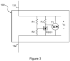
- FIG. 3 shows an example marine protection circuit 130.
- the example marine protection circuit 130 comprises a crowbar circuit connected between the first and the second terminals 131, 132. The voltage across the first and the second terminals is denoted V 0 .
- This example crowbar circuit comprises a so-called TRIAC T1.
- a TRIAC is a type of three-terminal thyristor that allows bidirectional current flow when triggered.
- a voltage regulator REG controls the gate of the TRIAC (the gate is the leftmost terminal of T1 in the figure).
- Resistors R1 and R2 divide the voltage V 0 to provide a reference voltage for the voltage regulator.
- the voltage regulator When the voltage across R2 is below a selectively set threshold value of the voltage regulator, the voltage regulator is in an off-state and conducts no or very little current. With proper dimensioning of R3, the TRIAC is in an off state, i.e., not conducting current, when the voltage across R2 is below the selectively set threshold. If V 0 increases, the voltage across R2 will eventually surpass the selectively set threshold. In that case, the voltage regulator will draw current, and the TRIAC will be latched on, i.e., start to conduct current.
- the crowbar circuit of Figure 3 thus presents a high resistance between the first and the second terminals 131, 132 when the TRIAC is unengaged.
- the high-resistance value is dominated by R1-R3, but is also affected somewhat by non-ideal resistive components of the voltage regulator and the TRIAC.
- the crowbar circuit furthermore presents low resistance between the first and the second terminals 131, 132 when the TRIAC is engaged. Ideally, the low-resistance value corresponds to a short circuit. In practice, however, non-ideal resistive components of the TRIAC are likely present.
- the crowbar circuit may be an active crowbar circuit.
- An active crowbar can remove the short circuit, i.e., be unengaged after it has been engaged. This allows the protection circuit to resume normal operation after it has been triggered.
- the marine protection circuit 130 may comprise means to be "fail safe", which is typically desired. Being fail safe means is that if the marine protection circuit 130 is compromised by, e.g., a surge or other fault, the circuit will engage (i.e., present the low resistance between the first and the second terminals).
Landscapes
- Engineering & Computer Science (AREA)
- Power Engineering (AREA)
- Mechanical Engineering (AREA)
- Chemical & Material Sciences (AREA)
- Emergency Protection Circuit Devices (AREA)
- Transportation (AREA)
- Physics & Mathematics (AREA)
- General Physics & Mathematics (AREA)
- Materials Engineering (AREA)
- Metallurgy (AREA)
- Organic Chemistry (AREA)
Applications Claiming Priority (1)
| Application Number | Priority Date | Filing Date | Title |
|---|---|---|---|
| SE2350534A SE546735C2 (en) | 2023-05-03 | 2023-05-03 | Marine protection circuit |
Publications (2)
| Publication Number | Publication Date |
|---|---|
| EP4459818A2 true EP4459818A2 (fr) | 2024-11-06 |
| EP4459818A3 EP4459818A3 (fr) | 2024-11-27 |
Family
ID=90971803
Family Applications (1)
| Application Number | Title | Priority Date | Filing Date |
|---|---|---|---|
| EP24173824.4A Withdrawn EP4459818A3 (fr) | 2023-05-03 | 2024-05-02 | Circuit de protection marin |
Country Status (4)
| Country | Link |
|---|---|
| US (1) | US20240372357A1 (fr) |
| EP (1) | EP4459818A3 (fr) |
| CN (1) | CN118899804A (fr) |
| SE (1) | SE546735C2 (fr) |
Family Cites Families (7)
| Publication number | Priority date | Publication date | Assignee | Title |
|---|---|---|---|---|
| US4117345A (en) * | 1977-08-22 | 1978-09-26 | Orville Balcom | Marine ground isolator |
| US5840164A (en) * | 1996-11-12 | 1998-11-24 | Brunswick Corporation | Galvanic isolator |
| US5747892A (en) * | 1997-01-06 | 1998-05-05 | Brunswick Corporation | Galvanic isolator fault monitor |
| US6559660B1 (en) * | 2001-08-20 | 2003-05-06 | Brunswick Corporation | Method and apparatus for testing an electrical system of a marine vessel |
| GB2480205A (en) * | 2009-03-05 | 2011-11-09 | Shoreline Products Ltd | Improvements in galvanic isolators |
| BR112013022224B1 (pt) * | 2011-03-02 | 2020-02-11 | Abb Schweiz Ag | Sistema para a operação de uma máquina elétrica e método para a proteção de uma unidade de controle de operação |
| EP2744062B1 (fr) * | 2012-12-14 | 2015-10-21 | ABB Technology AG | Système sous-marin doté de protection d'alimentation |
-
2023
- 2023-05-03 SE SE2350534A patent/SE546735C2/en not_active IP Right Cessation
-
2024
- 2024-04-26 US US18/647,571 patent/US20240372357A1/en active Pending
- 2024-04-30 CN CN202410533818.3A patent/CN118899804A/zh active Pending
- 2024-05-02 EP EP24173824.4A patent/EP4459818A3/fr not_active Withdrawn
Also Published As
| Publication number | Publication date |
|---|---|
| US20240372357A1 (en) | 2024-11-07 |
| SE2350534A1 (en) | 2024-11-04 |
| CN118899804A (zh) | 2024-11-05 |
| EP4459818A3 (fr) | 2024-11-27 |
| SE546735C2 (en) | 2025-02-11 |
Similar Documents
| Publication | Publication Date | Title |
|---|---|---|
| US11456677B2 (en) | Power converter protection circuit | |
| US4992904A (en) | Hybrid contactor for DC airframe power supply | |
| US10651838B2 (en) | DC power switching assembly and method | |
| US10727829B2 (en) | Power supply system and method | |
| US10862300B2 (en) | Power distribution system | |
| US20230278430A1 (en) | Safety circuit for an electrical traction system and method for controlling the system | |
| US5510659A (en) | Electrolysis inhibiting marine energy management system | |
| CN110574253B (zh) | 能量储存系统 | |
| EP4459818A2 (fr) | Circuit de protection marin | |
| US12467148B2 (en) | Impressed current cathodic protection system and a method of operating the system | |
| KR100630210B1 (ko) | 잠수함 | |
| EP3203601A1 (fr) | Système de contrôle d'alimentation | |
| Vicenzutti et al. | High voltage ship-to-shore connection for electric power supply support in landing operations: An analysis | |
| EP1391021B1 (fr) | Bloc d'alimentation | |
| AU2002255146A1 (en) | Power supply | |
| WO2008040054A1 (fr) | Circuit de commande | |
| KR20210042502A (ko) | 선박 전력 공급 시스템 | |
| US20260128581A1 (en) | Electrical protection circuit for energy storage unit | |
| WO2010100391A1 (fr) | Améliorations apportées aux isolateurs galvaniques | |
| EP4435989A1 (fr) | Circuit de protection électrique pour unité de stockage d'énergie | |
| HK1217933B (en) | Boat with electric drive | |
| HK1218995A1 (zh) | 具有浪涌电压保护的电源 |
Legal Events
| Date | Code | Title | Description |
|---|---|---|---|
| PUAI | Public reference made under article 153(3) epc to a published international application that has entered the european phase |
Free format text: ORIGINAL CODE: 0009012 |
|
| STAA | Information on the status of an ep patent application or granted ep patent |
Free format text: STATUS: THE APPLICATION HAS BEEN PUBLISHED |
|
| PUAL | Search report despatched |
Free format text: ORIGINAL CODE: 0009013 |
|
| AK | Designated contracting states |
Kind code of ref document: A2 Designated state(s): AL AT BE BG CH CY CZ DE DK EE ES FI FR GB GR HR HU IE IS IT LI LT LU LV MC ME MK MT NL NO PL PT RO RS SE SI SK SM TR |
|
| AK | Designated contracting states |
Kind code of ref document: A3 Designated state(s): AL AT BE BG CH CY CZ DE DK EE ES FI FR GB GR HR HU IE IS IT LI LT LU LV MC ME MK MT NL NO PL PT RO RS SE SI SK SM TR |
|
| RIC1 | Information provided on ipc code assigned before grant |
Ipc: H02H 5/10 20060101ALI20241022BHEP Ipc: H02H 3/14 20060101ALI20241022BHEP Ipc: H02H 3/02 20060101AFI20241022BHEP |
|
| STAA | Information on the status of an ep patent application or granted ep patent |
Free format text: STATUS: THE APPLICATION IS DEEMED TO BE WITHDRAWN |
|
| 18D | Application deemed to be withdrawn |
Effective date: 20250528 |