EP4459816A1 - Low or medium voltage switchgear - Google Patents
Low or medium voltage switchgear Download PDFInfo
- Publication number
- EP4459816A1 EP4459816A1 EP23171744.8A EP23171744A EP4459816A1 EP 4459816 A1 EP4459816 A1 EP 4459816A1 EP 23171744 A EP23171744 A EP 23171744A EP 4459816 A1 EP4459816 A1 EP 4459816A1
- Authority
- EP
- European Patent Office
- Prior art keywords
- compartment
- wall
- air
- duct
- vent
- Prior art date
- Legal status (The legal status is an assumption and is not a legal conclusion. Google has not performed a legal analysis and makes no representation as to the accuracy of the status listed.)
- Pending
Links
Images
Classifications
-
- H—ELECTRICITY
- H02—GENERATION; CONVERSION OR DISTRIBUTION OF ELECTRIC POWER
- H02B—BOARDS, SUBSTATIONS OR SWITCHING ARRANGEMENTS FOR THE SUPPLY OR DISTRIBUTION OF ELECTRIC POWER
- H02B1/00—Frameworks, boards, panels, desks, casings; Details of substations or switching arrangements
- H02B1/56—Cooling; Ventilation
- H02B1/565—Cooling; Ventilation for cabinets
-
- H—ELECTRICITY
- H02—GENERATION; CONVERSION OR DISTRIBUTION OF ELECTRIC POWER
- H02B—BOARDS, SUBSTATIONS OR SWITCHING ARRANGEMENTS FOR THE SUPPLY OR DISTRIBUTION OF ELECTRIC POWER
- H02B1/00—Frameworks, boards, panels, desks, casings; Details of substations or switching arrangements
- H02B1/26—Casings; Parts thereof or accessories therefor
- H02B1/28—Casings; Parts thereof or accessories therefor dustproof, splashproof, drip-proof, waterproof or flameproof
-
- H—ELECTRICITY
- H02—GENERATION; CONVERSION OR DISTRIBUTION OF ELECTRIC POWER
- H02B—BOARDS, SUBSTATIONS OR SWITCHING ARRANGEMENTS FOR THE SUPPLY OR DISTRIBUTION OF ELECTRIC POWER
- H02B1/00—Frameworks, boards, panels, desks, casings; Details of substations or switching arrangements
- H02B1/26—Casings; Parts thereof or accessories therefor
- H02B1/30—Cabinet-type casings; Parts thereof or accessories therefor
-
- H—ELECTRICITY
- H02—GENERATION; CONVERSION OR DISTRIBUTION OF ELECTRIC POWER
- H02B—BOARDS, SUBSTATIONS OR SWITCHING ARRANGEMENTS FOR THE SUPPLY OR DISTRIBUTION OF ELECTRIC POWER
- H02B1/00—Frameworks, boards, panels, desks, casings; Details of substations or switching arrangements
- H02B1/26—Casings; Parts thereof or accessories therefor
- H02B1/30—Cabinet-type casings; Parts thereof or accessories therefor
- H02B1/32—Mounting of devices therein
Definitions
- the present invention relates to low or medium voltage switchgears.
- Cooling is then an important design consideration, where heat generated by conductors needs to be removed
- Efficient cooling to remove heat means that the size of conductors can be reduced, saving material and cost, and components can be cooled mitigating their overheating
- cooling is performed through utilization of a series of flaps and openings that allow cold air to enter switchgear compartments. Another series of flaps and openings than lets hot air leave the switchgear.
- a compartment can be located at a position within the switchgear, where no fresh cold air can flow into this compartment.
- ventilation flaps can be used to circulate and ventilate the compartment located in this position.
- a busbar compartment can be located within a switchgear, adjacent to a circuit breaker compartment and/or adjacent to a cable connection compartment.
- the busbar compartment may have no wall that is at an outer wall of the switchgear, and/or air entering the switchgear can only do so through an outer wall of the circuit breaker compartment and/or through an outer wall of the cable connection compartment.
- air that enters the busbar compartment has already been heating due to passage through the circuit breaker compartment or cable connection compartment. As the air has already been heated, the cooling effect it has is diminished.
- a low or medium voltage switchgear comprising:
- An air intake or vent is located in an outer wall of the first compartment, and the outer wall separates the first compartment from ambient.
- An air intake or vent is located in a wall of the second compartment, and the wall separates the second compartment from the first compartment.
- An opening at a first end of the air conduit or duct is positioned around the air intake or vent located in the outer wall of the first compartment.
- An opening at a second end of the air conduit or duct is positioned around the air intake or vent located in the wall of the second compartment.
- the switchgear is configured to enable ambient air from outside the switchgear to enter the air intake or vent located in the outer wall of the first compartment, pass through the air conduit or duct, and exit through the intake or vent located in a wall of the second compartment to enter the second compartment.
- the switchgear is configured to enable ambient air from outside the switchgear to enter the air intake or vent located in the outer wall of the first compartment, pass through the air conduit or duct, and exit through the intake or vent located in a wall of the second compartment to enter the second compartment without entering a part of the first compartment surrounding the air conduit or duct.
- the opening at the first end of the air conduit or duct is positioned around and makes an air tight seal around the air intake or vent located in the outer wall of the first compartment.
- the opening at the second end of the air conduit or duct is positioned around and makes an air tight seal around the air intake or vent located in the wall of the second compartment.
- a wall of the air conduit or duct between the first end of the air conduit or duct and the second end of the air conduit or duct is air tight.
- the wall of the air conduit or duct between the first end of the air conduit or duct and the second end of the air conduit or duct comprises a thermal insulation material and/or electrical insulation material.
- an air intake or vent is located in a wall of the second compartment, and the wall separates the second compartment from ambient.
- an air intake or vent is located in a wall of the second compartment, and the wall separates the second compartment from a third compartment (50).
- a low or medium voltage switchgear comprising:
- An air intake or vent is located in an outer wall of the first compartment, and the outer wall separates the first compartment from ambient.
- An air intake or vent is located in an outer wall of the second compartment, and the outer wall separates the second compartment from ambient.
- An air intake or vent is located in a wall of the third compartment, and the wall separates the third compartment from the first compartment.
- An air intake or vent is located in a wall of the third compartment, and the wall separates the third compartment from the second compartment.
- An opening at a first end of the first air conduit or duct is positioned around the air intake or vent located in the outer wall of the first compartment.
- An opening at a first end of the second air conduit or duct is positioned around the air intake or vent (90) located in the outer wall of the second compartment.
- An opening at a second end of the first air conduit or duct is positioned around the air intake or vent located in the wall of the third compartment that separates the third compartment from the first compartment.
- An opening at a second end of the second air conduit or duct is positioned around the air intake or vent located in the wall of the third compartment (30) that separates the third compartment from the second compartment.
- the switchgear is configured to enable ambient air from outside the switchgear to enter the air intake or vent located in the outer wall of the first compartment, pass through the first air conduit or duct, and exit through the intake or vent located in the wall of the third compartment that separates the third compartment from the first compartment to enter the third compartment.
- the switchgear is configured to enable ambient air from outside the switchgear to enter the air intake or vent located in the outer wall of the second compartment, pass through the second air conduit or duct, and exit through the intake or vent located in the wall of the third compartment that separates the third compartment from the second compartment to enter the third compartment.
- the opening at the first end of the first air conduit or duct is positioned around and makes an air tight seal around the air intake or vent located in the outer wall of the first compartment.
- the opening at the first end of the second air conduit or duct is positioned around and makes an air tight seal around the air intake or vent located in the outer wall of the second compartment.
- the opening at the second end of the first air conduit or duct is positioned around and makes an air tight seal around the air intake or vent located in the wall of the third compartment that separates the third compartment from the second compartment.
- the opening at the second end of the second air conduit or duct is positioned around and makes an air tight seal around the air intake or vent located in the wall of the third compartment that separates the third compartment from the second compartment.
- a wall of the first air conduit or duct between the first end of the first air conduit or duct and the second end of the first air conduit or duct is air tight.
- a wall of the second air conduit or duct between the first end of the second air conduit or duct and the second end of the second air conduit or duct is air tight
- the wall of the first air conduit or duct between the first end of the first air conduit or duct and the second end of the first air conduit or duct comprises a thermal insulation material and/or electrical insulation material.
- the wall of the second air conduit or duct between the first end of the second air conduit or duct and the second end of the second air conduit or duct comprises a thermal insulation material and/or electrical insulation material
- an air intake or vent is located in a wall of the third compartment, and the wall separates the third compartment from ambient.
- an air intake or vent is located in a wall of the third compartment, and the wall separates the third compartment from a fourth compartment.
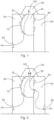
- Fig. 1 shows an example of a known switchgear design.
- the switchgear has a first compartment 20, which can be a circuit breaker department.
- the switchgear also has a second compartment 40, which can be a cable connection compartment.
- the switchgear also has a third compartment 30, which can be a busbar compartment.
- a vent or intake flap 60 in the wall of the first compartment permits the entry of cold air to the switchgear. This air cools the first compartment 20 and the components therein, cools the third compartment 30 by flowing through vents or flaps 70 in the wall of the third compartment separating the first compartment, and cools the second compartment 40 by flowing through vents of flaps 80 in the wall of the third compartment separating the second compartment.
- the air can also flow from the third compartment 30 into a further compartment 50 via a vent or flap 100, and can then flow to ambient by passing through another vent of flap in an outer wall of switchgear.
- FIG. 2 another example of a known switchgear has another vent or intake flap 90 in the wall of the second compartment 40 to provide for increased air flow into the switchgear to increase the cooling effect.
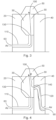
- Figs. 3-4 relate to new designs of switchgear.
- a new design of low, or medium voltage switchgear comprises:
- An air intake or vent 60, 90 is located in an outer wall of the first compartment 20, 40, and the outer wall separates the first compartment from ambient.
- An air intake or vent 130, 140 is located in a wall of the second compartment 30, and the wall separates the second compartment from the first compartment.
- An opening at a first end of the air conduit or duct 110, 120 is positioned around the air intake or vent 60, 90 located in the outer wall of the first compartment 20, 40.
- An opening at a second end of the air conduit or duct 110, 120 is positioned around the air intake or vent 130, 140 located in the wall of the second compartment 30.
- the switchgear is configured to enable ambient air from outside the switchgear to enter the air intake or vent 60, 90 located in the outer wall of the first compartment 20, 40, pass through the air conduit or duct 110, 120, and exit through the intake or vent 130, 140 located in a wall of the second compartment 30 to enter the second compartment 30
- the switchgear is configured to enable ambient air from outside the switchgear to enter the air intake or vent 60, 90 located in the outer wall of the first compartment 20, 40, pass through the air conduit or duct 110, 120, and exit through the intake or vent 130, 140 located in a wall of the second compartment 30 to enter the second compartment 30 without entering a part of the first compartment 20, 40 surrounding the air conduit or duct 110, 120.
- the opening at the first end of the air conduit or duct 110, 120 is positioned around and makes an air tight seal around the air intake or vent 60, 90 located in the outer wall of the first compartment 20, 40.
- the opening at the second end of the air conduit or duct 110, 120 is positioned around and makes an air tight seal around the air intake or vent 130, 140 located in the wall of the second compartment 30.
- the wall of the air conduit or duct 110, 120 between the first end of the air conduit or duct 110, 120 and the second end of the air conduit or duct 110, 120 comprises a thermal insulation material and/or electrical insulation material.
- an air intake or vent 100 is located in a wall of the second compartment 30, and the wall separates the second compartment from ambient or wherein the wall separates the second compartment from a third compartment (50).
- the first compartment is a circuit breaker compartment.
- the first compartment is a cable connection compartment.
- the second compartment is a busbar compartment.
- a new design of low or medium voltage switchgear comprises:
- An air intake or vent 60 is located in an outer wall of the first compartment 20, and the outer wall separates the first compartment 20 from ambient.
- An air intake or vent 90 is located in an outer wall of the second compartment 40, and the outer wall separates the second compartment 40 from ambient.
- An air intake or vent 130 is located in a wall of the third compartment 30, and the wall separates the third compartment from the first compartment.
- An air intake or vent 140 is located in a wall of the third compartment 30, and the wall separates the third compartment from the second compartment.
- An opening at a first end of the first air conduit or duct 110 is positioned around the air intake or vent 60 located in the outer wall of the first compartment 20.
- An opening at a first end of the second air conduit or duct 120 is positioned around the air intake or vent 90 located in the outer wall of the second compartment 40.
- An opening at a second end of the first air conduit or duct 110 is positioned around the air intake or vent 130 located in the wall of the third compartment 30 that separates the third compartment from the first compartment.
- An opening at a second end of the second air conduit or duct 120 is positioned around the air intake or vent 140 located in the wall of the third compartment 30 that separates the third compartment from the second compartment.
- the switchgear is configured to enable ambient air from outside the switchgear to enter the air intake or vent 60 located in the outer wall of the first compartment 20, pass through the first air conduit or duct 110, and exit through the intake or vent 130 located in the wall of the third compartment 30 that separates the third compartment from the first compartment to enter the third compartment 30.
- the switchgear is configured to enable ambient air from outside the switchgear to enter the air intake or vent 90 located in the outer wall of the second compartment 40, pass through the second air conduit or duct 120, and exit through the intake or vent 140 located in the wall of the third compartment 30 that separates the third compartment from the second compartment to enter the third compartment 30.
- the switchgear is configured to enable ambient air from outside the switchgear to enter the air intake or vent 60 located in the outer wall of the first compartment 20, pass through the first air conduit or duct 110, and exit through the intake or vent 130 located in the wall of the third compartment 30 that separates the third compartment from the first compartment to enter the third compartment 30 without entering a part of the first compartment 20 surrounding the first air conduit or duct 110.
- the switchgear is configured to enable ambient air from outside the switchgear to enter the air intake or vent 90 located in the outer wall of the second compartment 40, pass through the second air conduit or duct 120, and exit through the intake or vent 140 located in the wall of the third compartment 30 that separates the third compartment from the second compartment to enter the third compartment 30 without entering a part of the second compartment 40 surrounding the second air conduit or duct 120.
- the opening at the first end of the first air conduit or duct 110 is positioned around and makes an air tight seal around the air intake or vent 60 located in the outer wall of the first compartment 20.
- the opening at the first end of the second air conduit or duct 120 is positioned around and makes an air tight seal around the air intake or vent 90 located in the outer wall of the second compartment 40.
- the opening at the second end of the first air conduit or duct 110 is positioned around and makes an air tight seal around the air intake or vent 130 located in the wall of the third compartment 30 that separates the third compartment from the second compartment.
- the opening at the second end of the second air conduit or duct 120 is positioned around and makes an air tight seal around the air intake or vent 140 located in the wall of the third compartment 30 that separates the third compartment from the second compartment.
- a wall of the first air conduit or duct 110 between the first end of the first air conduit or duct 110 and the second end of the first air conduit or duct 110 is air tight; and wherein a wall of the second air conduit or duct 120 between the first end of the second air conduit or duct 120 and the second end of the second air conduit or duct 120 is air tight.
- the wall of the first air conduit or duct 110 between the first end of the first air conduit or duct 110 and the second end of the first air conduit or duct 110 comprises a thermal insulation material and/or electrical insulation material.
- the wall of the second air conduit or duct 120 between the first end of the second air conduit or duct 120 and the second end of the second air conduit or duct 120 comprises a thermal insulation material and/or electrical insulation material
- an air intake or vent 100 is located in a wall of the third compartment 30, and the wall separates the third compartment from ambient or wherein the wall separates the third compartment from a fourth compartment 50.
- the first compartment is a circuit breaker compartment.
- the second compartment is a cable connection compartment.
- the third compartment is a busbar compartment.
- the new designs make use of air ducts. These ducts guide cold air from ambient air without mixing it with hot air in adjacent compartments to the compartment to be cooled. Therefore, air supplied into a compartments, that previously would have been pre-heated, now remains cold, which greatly increases the cooling potential of the air and improves the cooling of components located in the compartment.
- the amount of air entering the internal compartment via the ducts can be lower than when just vents/flaps are used, but because the air temperature is lower the cooling potential is actually increased.
- the duct or ducts can be strategically positioned as required.
- the cooling air duct or ducts can be constructed from heat insulating and electrically insulating material, like plastic. This way the air inside the duct remains cold even if the duct passes through hot air or close to hot electric parts. Because plastic is an electrically insulating material, the risk of di-electric effects are eliminated. In some applications this duct, or one of more than one ducts, can be integrated into structural component of the compartment, therefore the material can be also metallic or other components from what the structure of the switchgear is made.
Landscapes
- Engineering & Computer Science (AREA)
- Power Engineering (AREA)
- Patch Boards (AREA)
Abstract
The present invention relates to a low or medium voltage switchgear, comprising:- a first compartment (20, 40);- a second compartment (30); and- an air conduit or duct (110, 120);wherein an air intake or vent (60, 90) is located in an outer wall of the first compartment (20, 40), and wherein the outer wall separates the first compartment from ambient;wherein an air intake or vent (130, 140) is located in a wall of the second compartment (30), and wherein the wall separates the second compartment from the first compartment;wherein an opening at a first end of the air conduit or duct (110, 120) is positioned around the air intake or vent (60, 90) located in the outer wall of the first compartment (20, 40); andwherein an opening at a second end of the air conduit or duct (110, 120) is positioned around the air intake or vent (130, 140) located in the wall of the second compartment (30).
Description
- The present invention relates to low or medium voltage switchgears.
- In switchgear, conductors inside the switchgear generate heat when conducting current due to Joule heating.
- Cooling is then an important design consideration, where heat generated by conductors needs to be removed
- Efficient cooling to remove heat, means that the size of conductors can be reduced, saving material and cost, and components can be cooled mitigating their overheating
- In low and medium voltage applications, cooling is performed through utilization of a series of flaps and openings that allow cold air to enter switchgear compartments. Another series of flaps and openings than lets hot air leave the switchgear.
- In some situations a compartment can be located at a position within the switchgear, where no fresh cold air can flow into this compartment. To enforce the cooling effect in such a situation, ventilation flaps can be used to circulate and ventilate the compartment located in this position.
- For example, a busbar compartment can be located within a switchgear, adjacent to a circuit breaker compartment and/or adjacent to a cable connection compartment. The busbar compartment may have no wall that is at an outer wall of the switchgear, and/or air entering the switchgear can only do so through an outer wall of the circuit breaker compartment and/or through an outer wall of the cable connection compartment. In this situation, then air that enters the busbar compartment has already been heating due to passage through the circuit breaker compartment or cable connection compartment. As the air has already been heated, the cooling effect it has is diminished.
- There is a need to address these issues.
- Therefore, it would be advantageous to have an improved switchgear.
- The object of the present invention is solved with the subject matter of the independent claims, wherein further embodiments are incorporated in the dependent claims.
- In a first aspect, there is provided a low or medium voltage switchgear, comprising:
- a first compartment;
- a second compartment; and
- an air conduit or duct.
- An air intake or vent is located in an outer wall of the first compartment, and the outer wall separates the first compartment from ambient. An air intake or vent is located in a wall of the second compartment, and the wall separates the second compartment from the first compartment. An opening at a first end of the air conduit or duct is positioned around the air intake or vent located in the outer wall of the first compartment. An opening at a second end of the air conduit or duct is positioned around the air intake or vent located in the wall of the second compartment.
- In an example, the switchgear is configured to enable ambient air from outside the switchgear to enter the air intake or vent located in the outer wall of the first compartment, pass through the air conduit or duct, and exit through the intake or vent located in a wall of the second compartment to enter the second compartment.
- In an example, the switchgear is configured to enable ambient air from outside the switchgear to enter the air intake or vent located in the outer wall of the first compartment, pass through the air conduit or duct, and exit through the intake or vent located in a wall of the second compartment to enter the second compartment without entering a part of the first compartment surrounding the air conduit or duct.
- In an example, the opening at the first end of the air conduit or duct is positioned around and makes an air tight seal around the air intake or vent located in the outer wall of the first compartment.
- In an example, the opening at the second end of the air conduit or duct is positioned around and makes an air tight seal around the air intake or vent located in the wall of the second compartment.
- In an example, a wall of the air conduit or duct between the first end of the air conduit or duct and the second end of the air conduit or duct is air tight.
- In an example, the wall of the air conduit or duct between the first end of the air conduit or duct and the second end of the air conduit or duct comprises a thermal insulation material and/or electrical insulation material.
- In an example, an air intake or vent is located in a wall of the second compartment, and the wall separates the second compartment from ambient.
- In an example, an air intake or vent is located in a wall of the second compartment, and the wall separates the second compartment from a third compartment (50).
- In a second aspect, there is provided a low or medium voltage switchgear, comprising:
- a first compartment;
- a second compartment;
- a third compartment;
- a first air conduit or duct; and
- a second air conduit or duct.
- An air intake or vent is located in an outer wall of the first compartment, and the outer wall separates the first compartment from ambient. An air intake or vent is located in an outer wall of the second compartment, and the outer wall separates the second compartment from ambient. An air intake or vent is located in a wall of the third compartment, and the wall separates the third compartment from the first compartment. An air intake or vent is located in a wall of the third compartment, and the wall separates the third compartment from the second compartment. An opening at a first end of the first air conduit or duct is positioned around the air intake or vent located in the outer wall of the first compartment. An opening at a first end of the second air conduit or duct is positioned around the air intake or vent (90) located in the outer wall of the second compartment. An opening at a second end of the first air conduit or duct is positioned around the air intake or vent located in the wall of the third compartment that separates the third compartment from the first compartment. An opening at a second end of the second air conduit or duct is positioned around the air intake or vent located in the wall of the third compartment (30) that separates the third compartment from the second compartment.
- In an example, the switchgear is configured to enable ambient air from outside the switchgear to enter the air intake or vent located in the outer wall of the first compartment, pass through the first air conduit or duct, and exit through the intake or vent located in the wall of the third compartment that separates the third compartment from the first compartment to enter the third compartment.
- In an example, the switchgear is configured to enable ambient air from outside the switchgear to enter the air intake or vent located in the outer wall of the second compartment, pass through the second air conduit or duct, and exit through the intake or vent located in the wall of the third compartment that separates the third compartment from the second compartment to enter the third compartment.
- In an example, the opening at the first end of the first air conduit or duct is positioned around and makes an air tight seal around the air intake or vent located in the outer wall of the first compartment.
- In an example, the opening at the first end of the second air conduit or duct is positioned around and makes an air tight seal around the air intake or vent located in the outer wall of the second compartment.
- In an example, the opening at the second end of the first air conduit or duct is positioned around and makes an air tight seal around the air intake or vent located in the wall of the third compartment that separates the third compartment from the second compartment.
- In an example, the opening at the second end of the second air conduit or duct is positioned around and makes an air tight seal around the air intake or vent located in the wall of the third compartment that separates the third compartment from the second compartment.
- In an example, a wall of the first air conduit or duct between the first end of the first air conduit or duct and the second end of the first air conduit or duct is air tight.
- In an example, a wall of the second air conduit or duct between the first end of the second air conduit or duct and the second end of the second air conduit or duct is air tight
- In an example, the wall of the first air conduit or duct between the first end of the first air conduit or duct and the second end of the first air conduit or duct comprises a thermal insulation material and/or electrical insulation material.
- In an example, the wall of the second air conduit or duct between the first end of the second air conduit or duct and the second end of the second air conduit or duct comprises a thermal insulation material and/or electrical insulation material
- In an example, an air intake or vent is located in a wall of the third compartment, and the wall separates the third compartment from ambient.
- In an example, an air intake or vent is located in a wall of the third compartment, and the wall separates the third compartment from a fourth compartment.
- The above aspect and examples will become apparent from and be elucidated with reference to the embodiments described hereinafter.
- Exemplary embodiments will be described in the following with reference to the following drawing:
-
Fig. 1 shows a known switchgear design; -
Fig. 2 shows a known switchgear design; -
Fig. 3 shows a new switchgear design; and -
Fig. 4 shows a new switchgear design. -
Fig. 1 shows an example of a known switchgear design. The switchgear has afirst compartment 20, which can be a circuit breaker department. The switchgear also has asecond compartment 40, which can be a cable connection compartment. The switchgear also has athird compartment 30, which can be a busbar compartment. A vent orintake flap 60 in the wall of the first compartment permits the entry of cold air to the switchgear. This air cools thefirst compartment 20 and the components therein, cools thethird compartment 30 by flowing through vents or flaps 70 in the wall of the third compartment separating the first compartment, and cools thesecond compartment 40 by flowing through vents offlaps 80 in the wall of the third compartment separating the second compartment. The air can also flow from thethird compartment 30 into afurther compartment 50 via a vent orflap 100, and can then flow to ambient by passing through another vent of flap in an outer wall of switchgear. - As shown in
Fig. 2 , another example of a known switchgear has another vent orintake flap 90 in the wall of thesecond compartment 40 to provide for increased air flow into the switchgear to increase the cooling effect. - However, the problem with these designs is that the air that cools the
third compartment 30 and the components therein has already been heater before it enters thethird compartment 30, and the cooling effect is diminished. - The inventors came up with the following new designs to overcome this problem.
-
Figs. 3-4 relate to new designs of switchgear. - In an example, a new design of low, or medium voltage switchgear comprises:
- a
first compartment - a
second compartment 30; and - an air conduit or
duct - An air intake or vent 60, 90 is located in an outer wall of the
first compartment second compartment 30, and the wall separates the second compartment from the first compartment. An opening at a first end of the air conduit orduct first compartment duct second compartment 30. - According to an example, the switchgear is configured to enable ambient air from outside the switchgear to enter the air intake or vent 60, 90 located in the outer wall of the
first compartment duct second compartment 30 to enter thesecond compartment 30 - According to an example, the switchgear is configured to enable ambient air from outside the switchgear to enter the air intake or vent 60, 90 located in the outer wall of the
first compartment duct second compartment 30 to enter thesecond compartment 30 without entering a part of thefirst compartment duct - According to an example, the opening at the first end of the air conduit or
duct first compartment - According to an example, the opening at the second end of the air conduit or
duct second compartment 30. - Switchgear according to any of claims 1-5, wherein a wall of the air conduit or duct (110, 120) between the first end of the air conduit or duct (110, 120) and the second end of the air conduit or duct (110, 120) is air tight.
- According to an example, the wall of the air conduit or
duct duct duct - According to an example, an air intake or vent 100 is located in a wall of the
second compartment 30, and the wall separates the second compartment from ambient or wherein the wall separates the second compartment from a third compartment (50). - In an example, the first compartment is a circuit breaker compartment.
- In an example, the first compartment is a cable connection compartment.
- In an example, the second compartment is a busbar compartment.
- In an example, a new design of low or medium voltage switchgear, comprises:
- a
first compartment 20; - a
second compartment 40; - a
third compartment 30; - a first air conduit or
duct 110; and - a second air conduit or
duct 120. - An air intake or vent 60 is located in an outer wall of the
first compartment 20, and the outer wall separates thefirst compartment 20 from ambient. An air intake or vent 90 is located in an outer wall of thesecond compartment 40, and the outer wall separates thesecond compartment 40 from ambient. An air intake or vent 130 is located in a wall of thethird compartment 30, and the wall separates the third compartment from the first compartment. An air intake or vent 140 is located in a wall of thethird compartment 30, and the wall separates the third compartment from the second compartment. An opening at a first end of the first air conduit orduct 110 is positioned around the air intake or vent 60 located in the outer wall of thefirst compartment 20. An opening at a first end of the second air conduit orduct 120 is positioned around the air intake or vent 90 located in the outer wall of thesecond compartment 40. An opening at a second end of the first air conduit orduct 110 is positioned around the air intake or vent 130 located in the wall of thethird compartment 30 that separates the third compartment from the first compartment. An opening at a second end of the second air conduit orduct 120 is positioned around the air intake or vent 140 located in the wall of thethird compartment 30 that separates the third compartment from the second compartment. - According to an example, the switchgear is configured to enable ambient air from outside the switchgear to enter the air intake or vent 60 located in the outer wall of the
first compartment 20, pass through the first air conduit orduct 110, and exit through the intake or vent 130 located in the wall of thethird compartment 30 that separates the third compartment from the first compartment to enter thethird compartment 30. - According to an example, the switchgear is configured to enable ambient air from outside the switchgear to enter the air intake or vent 90 located in the outer wall of the
second compartment 40, pass through the second air conduit orduct 120, and exit through the intake or vent 140 located in the wall of thethird compartment 30 that separates the third compartment from the second compartment to enter thethird compartment 30. - In an example, the switchgear is configured to enable ambient air from outside the switchgear to enter the air intake or vent 60 located in the outer wall of the
first compartment 20, pass through the first air conduit orduct 110, and exit through the intake or vent 130 located in the wall of thethird compartment 30 that separates the third compartment from the first compartment to enter thethird compartment 30 without entering a part of thefirst compartment 20 surrounding the first air conduit orduct 110. - In an example, the switchgear is configured to enable ambient air from outside the switchgear to enter the air intake or vent 90 located in the outer wall of the
second compartment 40, pass through the second air conduit orduct 120, and exit through the intake or vent 140 located in the wall of thethird compartment 30 that separates the third compartment from the second compartment to enter thethird compartment 30 without entering a part of thesecond compartment 40 surrounding the second air conduit orduct 120. - According to an example, the opening at the first end of the first air conduit or
duct 110 is positioned around and makes an air tight seal around the air intake or vent 60 located in the outer wall of thefirst compartment 20. - According to an example, the opening at the first end of the second air conduit or
duct 120 is positioned around and makes an air tight seal around the air intake or vent 90 located in the outer wall of thesecond compartment 40. - According to an example, the opening at the second end of the first air conduit or
duct 110 is positioned around and makes an air tight seal around the air intake or vent 130 located in the wall of thethird compartment 30 that separates the third compartment from the second compartment. - According to an example, the opening at the second end of the second air conduit or
duct 120 is positioned around and makes an air tight seal around the air intake or vent 140 located in the wall of thethird compartment 30 that separates the third compartment from the second compartment. - According to an example, a wall of the first air conduit or
duct 110 between the first end of the first air conduit orduct 110 and the second end of the first air conduit orduct 110 is air tight; and wherein a wall of the second air conduit orduct 120 between the first end of the second air conduit orduct 120 and the second end of the second air conduit orduct 120 is air tight. - According to an example, the wall of the first air conduit or
duct 110 between the first end of the first air conduit orduct 110 and the second end of the first air conduit orduct 110 comprises a thermal insulation material and/or electrical insulation material. - According to an example, the wall of the second air conduit or
duct 120 between the first end of the second air conduit orduct 120 and the second end of the second air conduit orduct 120 comprises a thermal insulation material and/or electrical insulation material - According to an example, an air intake or vent 100 is located in a wall of the
third compartment 30, and the wall separates the third compartment from ambient or wherein the wall separates the third compartment from afourth compartment 50. - In an example, the first compartment is a circuit breaker compartment.
- In an example, the second compartment is a cable connection compartment.
- In an example, the third compartment is a busbar compartment.
- Thus, the new designs make use of air ducts. These ducts guide cold air from ambient air without mixing it with hot air in adjacent compartments to the compartment to be cooled. Therefore, air supplied into a compartments, that previously would have been pre-heated, now remains cold, which greatly increases the cooling potential of the air and improves the cooling of components located in the compartment.
- It is to be noted that, the amount of air entering the internal compartment via the ducts can be lower than when just vents/flaps are used, but because the air temperature is lower the cooling potential is actually increased. The duct or ducts can be strategically positioned as required.
- The cooling air duct or ducts can be constructed from heat insulating and electrically insulating material, like plastic. This way the air inside the duct remains cold even if the duct passes through hot air or close to hot electric parts. Because plastic is an electrically insulating material, the risk of di-electric effects are eliminated. In some applications this duct, or one of more than one ducts, can be integrated into structural component of the compartment, therefore the material can be also metallic or other components from what the structure of the switchgear is made.
Claims (15)
- A low or medium voltage switchgear, comprising:- a first compartment (20, 40);- a second compartment (30); and- an air conduit or duct (110, 120);wherein an air intake or vent (60, 90) is located in an outer wall of the first compartment (20, 40), and wherein the outer wall separates the first compartment from ambient;wherein an air intake or vent (130, 140) is located in a wall of the second compartment (30), and wherein the wall separates the second compartment from the first compartment;wherein an opening at a first end of the air conduit or duct (110, 120) is positioned around the air intake or vent (60, 90) located in the outer wall of the first compartment (20, 40); andwherein an opening at a second end of the air conduit or duct (110, 120) is positioned around the air intake or vent (130, 140) located in the wall of the second compartment (30).
- Switchgear according to claim 1, wherein the switchgear is configured to enable ambient air from outside the switchgear to enter the air intake or vent (60, 90) located in the outer wall of the first compartment (20, 40), pass through the air conduit or duct (110, 120), and exit through the intake or vent (130, 140) located in a wall of the second compartment (30) to enter the second compartment (30).
- Switchgear according to any of claims 1-2, wherein the switchgear is configured to enable ambient air from outside the switchgear to enter the air intake or vent (60, 90) located in the outer wall of the first compartment (20, 40), pass through the air conduit or duct (110, 120), and exit through the intake or vent (130, 140) located in a wall of the second compartment (30) to enter the second compartment (30) without entering a part of the first compartment (20, 40) surrounding the air conduit or duct (110, 120).
- Switchgear according to any of claims 1-3, wherein the opening at the first end of the air conduit or duct (110, 120) is positioned around and makes an air tight seal around the air intake or vent (60, 90) located in the outer wall of the first compartment (20, 40).
- Switchgear according to any of claims 1-4, wherein the opening at the second end of the air conduit or duct (110, 120) is positioned around and makes an air tight seal around the air intake or vent (130, 140) located in the wall of the second compartment (30).
- Switchgear according to any of claims 1-5, wherein a wall of the air conduit or duct (110, 120) between the first end of the air conduit or duct (110, 120) and the second end of the air conduit or duct (110, 120) is air tight.
- Switchgear according to claim 6, wherein the wall of the air conduit or duct (110, 120) between the first end of the air conduit or duct (110, 120) and the second end of the air conduit or duct (110, 120) comprises a thermal insulation material and/or electrical insulation material.
- Switchgear according to any of claims 1-7, wherein an air intake or vent (100) is located in a wall of the second compartment (30), and wherein the wall separates the second compartment from ambient or wherein the wall separates the second compartment from a third compartment (50).
- A low or medium voltage switchgear, comprising:- a first compartment (20);- a second compartment (40);- a third compartment (30);- a first air conduit or duct (110); and- a second air conduit or duct (120);wherein an air intake or vent (60) is located in an outer wall of the first compartment (20), and wherein the outer wall separates the first compartment (20) from ambient;wherein an air intake or vent (90) is located in an outer wall of the second compartment (40), and wherein the outer wall separates the second compartment (40) from ambient;wherein an air intake or vent (130) is located in a wall of the third compartment (30), and wherein the wall separates the third compartment from the first compartment;wherein an air intake or vent (140) is located in a wall of the third compartment (30), and wherein the wall separates the third compartment from the second compartment;wherein an opening at a first end of the first air conduit or duct (110) is positioned around the air intake or vent (60) located in the outer wall of the first compartment (20);wherein an opening at a first end of the second air conduit or duct (120) is positioned around the air intake or vent (90) located in the outer wall of the second compartment (40);wherein an opening at a second end of the first air conduit or duct (110) is positioned around the air intake or vent (130) located in the wall of the third compartment (30) that separates the third compartment from the first compartment; andwherein an opening at a second end of the second air conduit or duct (120) is positioned around the air intake or vent (140) located in the wall of the third compartment (30) that separates the third compartment from the second compartment.
- Switchgear according to claim 9, wherein the switchgear is configured to enable ambient air from outside the switchgear to enter the air intake or vent (60) located in the outer wall of the first compartment (20), pass through the first air conduit or duct (110), and exit through the intake or vent (130) located in the wall of the third compartment (30) that separates the third compartment from the first compartment to enter the third compartment (30); and wherein the switchgear is configured to enable ambient air from outside the switchgear to enter the air intake or vent (90) located in the outer wall of the second compartment (40), pass through the second air conduit or duct (120), and exit through the intake or vent (140) located in the wall of the third compartment (30) that separates the third compartment from the second compartment to enter the third compartment (30).
- Switchgear according to any of claims 9-10, wherein the opening at the first end of the first air conduit or duct (110) is positioned around and makes an air tight seal around the air intake or vent (60) located in the outer wall of the first compartment (20); and wherein the opening at the first end of the second air conduit or duct (120) is positioned around and makes an air tight seal around the air intake or vent (90) located in the outer wall of the second compartment (40).
- Switchgear according to any of claims 9-11, wherein the opening at the second end of the first air conduit or duct (110) is positioned around and makes an air tight seal around the air intake or vent (130) located in the wall of the third compartment (30) that separates the third compartment from the second compartment; and wherein the opening at the second end of the second air conduit or duct (120) is positioned around and makes an air tight seal around the air intake or vent (140) located in the wall of the third compartment (30) that separates the third compartment from the second compartment.
- Switchgear according to any of claims 9-12, wherein a wall of the first air conduit or duct (110) between the first end of the first air conduit or duct (110) and the second end of the first air conduit or duct (110) is air tight; and wherein a wall of the second air conduit or duct (120) between the first end of the second air conduit or duct (120) and the second end of the second air conduit or duct (120) is air tight
- Switchgear according to claim 13, wherein the wall of the first air conduit or duct (110) between the first end of the first air conduit or duct (110) and the second end of the first air conduit or duct (110) comprises a thermal insulation material and/or electrical insulation material; and/or wherein the wall of the second air conduit or duct (120) between the first end of the second air conduit or duct (120) and the second end of the second air conduit or duct (120) comprises a thermal insulation material and/or electrical insulation material
- Switchgear according to any of claims 9-14, wherein an air intake or vent (100) is located in a wall of the third compartment (30), and wherein the wall separates the third compartment from ambient or wherein the wall separates the third compartment from a fourth compartment (50).
Priority Applications (2)
| Application Number | Priority Date | Filing Date | Title |
|---|---|---|---|
| EP23171744.8A EP4459816A1 (en) | 2023-05-05 | 2023-05-05 | Low or medium voltage switchgear |
| CN202410537075.7A CN118899765A (en) | 2023-05-05 | 2024-04-30 | Low or medium voltage switchgear |
Applications Claiming Priority (1)
| Application Number | Priority Date | Filing Date | Title |
|---|---|---|---|
| EP23171744.8A EP4459816A1 (en) | 2023-05-05 | 2023-05-05 | Low or medium voltage switchgear |
Publications (1)
| Publication Number | Publication Date |
|---|---|
| EP4459816A1 true EP4459816A1 (en) | 2024-11-06 |
Family
ID=86330076
Family Applications (1)
| Application Number | Title | Priority Date | Filing Date |
|---|---|---|---|
| EP23171744.8A Pending EP4459816A1 (en) | 2023-05-05 | 2023-05-05 | Low or medium voltage switchgear |
Country Status (2)
| Country | Link |
|---|---|
| EP (1) | EP4459816A1 (en) |
| CN (1) | CN118899765A (en) |
Citations (4)
| Publication number | Priority date | Publication date | Assignee | Title |
|---|---|---|---|---|
| US3626251A (en) * | 1970-01-19 | 1971-12-07 | Bendix Corp | Air cooling system for cabinet mounted equipment |
| US4528614A (en) * | 1983-10-07 | 1985-07-09 | Westinghouse Electric Corp. | Electric control center having integral air-ventilation system |
| US20110036554A1 (en) * | 2009-08-14 | 2011-02-17 | Sinitec Vertriebsgesellschaft Mbh | Cooling arrangement, server rack and method for controlling a cooling arrangement |
| CN206283132U (en) * | 2016-12-30 | 2017-06-27 | 宁波德沃智能股份有限公司 | A kind of low-tension switch cabinet suitable for severe cold area |
-
2023
- 2023-05-05 EP EP23171744.8A patent/EP4459816A1/en active Pending
-
2024
- 2024-04-30 CN CN202410537075.7A patent/CN118899765A/en active Pending
Patent Citations (4)
| Publication number | Priority date | Publication date | Assignee | Title |
|---|---|---|---|---|
| US3626251A (en) * | 1970-01-19 | 1971-12-07 | Bendix Corp | Air cooling system for cabinet mounted equipment |
| US4528614A (en) * | 1983-10-07 | 1985-07-09 | Westinghouse Electric Corp. | Electric control center having integral air-ventilation system |
| US20110036554A1 (en) * | 2009-08-14 | 2011-02-17 | Sinitec Vertriebsgesellschaft Mbh | Cooling arrangement, server rack and method for controlling a cooling arrangement |
| CN206283132U (en) * | 2016-12-30 | 2017-06-27 | 宁波德沃智能股份有限公司 | A kind of low-tension switch cabinet suitable for severe cold area |
Non-Patent Citations (1)
| Title |
|---|
| LUKA: "Quality Guide Air duct systems 2022-06", 31 May 2022 (2022-05-31), pages 1 - 151, XP093089707, Retrieved from the Internet <URL:https://www.luka.nl/cms/public/files/2022-06/luka-handboek-2022-06-eng-.pdf?99f462046f> [retrieved on 20231009] * |
Also Published As
| Publication number | Publication date |
|---|---|
| CN118899765A (en) | 2024-11-05 |
Similar Documents
| Publication | Publication Date | Title |
|---|---|---|
| US20240429650A1 (en) | Electrical connector assembly with thermal management | |
| CN115989158A (en) | vehicle charging station | |
| US10230221B2 (en) | Spout for switchgear, switchgear having spout, and method thereof | |
| JP7317922B2 (en) | Cooling fluid induction housing and electrical connector system with cooling fluid induction housing | |
| US9631836B2 (en) | Device for electrically heating fluid for a motor vehicle, and related heating and/or air-conditioning apparatus | |
| US4118755A (en) | Self-cooled metal-clad switchgear | |
| CN112956092A (en) | Gas Insulated Switchgear | |
| US11304330B2 (en) | Low-voltage switching device having a defined cooling arrangement | |
| EP4459816A1 (en) | Low or medium voltage switchgear | |
| EP3299743B1 (en) | Electric heater | |
| CN105051853A (en) | Gas cooler for a medium voltage switchgear assembly | |
| JP5879914B2 (en) | Battery module for vehicles | |
| CN105845466B (en) | Fixed contact for joining a busbar and a sliding contact of an electrical switching device | |
| CN110739632A (en) | A contact box and switch cabinet using the same | |
| EP4560674A1 (en) | Switchgear | |
| EP4564390A1 (en) | Circuit breaker pole part | |
| CN218160074U (en) | Heat radiation structure and circuit breaker | |
| CN102263378A (en) | 4,000A contact box | |
| US2953623A (en) | Forced convection cooling for isolated phase bus | |
| CN219544509U (en) | Refrigerating system for charging cabinet | |
| EP4539277A1 (en) | Switchgear | |
| US20260081087A1 (en) | Circuit Breaker | |
| US20200288599A1 (en) | Low-voltage switching device having an asymmetrically guided air flow-based cooling system | |
| US20210410325A1 (en) | Electric Controller | |
| EP4557538A1 (en) | Switchgear |
Legal Events
| Date | Code | Title | Description |
|---|---|---|---|
| PUAI | Public reference made under article 153(3) epc to a published international application that has entered the european phase |
Free format text: ORIGINAL CODE: 0009012 |
|
| STAA | Information on the status of an ep patent application or granted ep patent |
Free format text: STATUS: THE APPLICATION HAS BEEN PUBLISHED |
|
| AK | Designated contracting states |
Kind code of ref document: A1 Designated state(s): AL AT BE BG CH CY CZ DE DK EE ES FI FR GB GR HR HU IE IS IT LI LT LU LV MC ME MK MT NL NO PL PT RO RS SE SI SK SM TR |
|
| STAA | Information on the status of an ep patent application or granted ep patent |
Free format text: STATUS: REQUEST FOR EXAMINATION WAS MADE |
|
| 17P | Request for examination filed |
Effective date: 20250408 |