EP4459809A1 - Track adapter, track, and electrical system - Google Patents
Track adapter, track, and electrical system Download PDFInfo
- Publication number
- EP4459809A1 EP4459809A1 EP22914557.8A EP22914557A EP4459809A1 EP 4459809 A1 EP4459809 A1 EP 4459809A1 EP 22914557 A EP22914557 A EP 22914557A EP 4459809 A1 EP4459809 A1 EP 4459809A1
- Authority
- EP
- European Patent Office
- Prior art keywords
- track
- clamping piece
- connection body
- piece
- power supply
- Prior art date
- Legal status (The legal status is an assumption and is not a legal conclusion. Google has not performed a legal analysis and makes no representation as to the accuracy of the status listed.)
- Pending
Links
Images




Classifications
-
- H—ELECTRICITY
- H01—ELECTRIC ELEMENTS
- H01R—ELECTRICALLY-CONDUCTIVE CONNECTIONS; STRUCTURAL ASSOCIATIONS OF A PLURALITY OF MUTUALLY-INSULATED ELECTRICAL CONNECTING ELEMENTS; COUPLING DEVICES; CURRENT COLLECTORS
- H01R25/00—Coupling parts adapted for simultaneous co-operation with two or more identical counterparts, e.g. for distributing energy to two or more circuits
- H01R25/14—Rails or bus-bars constructed so that the counterparts can be connected thereto at any point along their length
- H01R25/142—Their counterparts
-
- H—ELECTRICITY
- H01—ELECTRIC ELEMENTS
- H01R—ELECTRICALLY-CONDUCTIVE CONNECTIONS; STRUCTURAL ASSOCIATIONS OF A PLURALITY OF MUTUALLY-INSULATED ELECTRICAL CONNECTING ELEMENTS; COUPLING DEVICES; CURRENT COLLECTORS
- H01R25/00—Coupling parts adapted for simultaneous co-operation with two or more identical counterparts, e.g. for distributing energy to two or more circuits
- H01R25/14—Rails or bus-bars constructed so that the counterparts can be connected thereto at any point along their length
-
- F—MECHANICAL ENGINEERING; LIGHTING; HEATING; WEAPONS; BLASTING
- F21—LIGHTING
- F21S—NON-PORTABLE LIGHTING DEVICES; SYSTEMS THEREOF; VEHICLE LIGHTING DEVICES SPECIALLY ADAPTED FOR VEHICLE EXTERIORS
- F21S8/00—Lighting devices intended for fixed installation
- F21S8/04—Lighting devices intended for fixed installation intended only for mounting on a ceiling or the like overhead structures
- F21S8/06—Lighting devices intended for fixed installation intended only for mounting on a ceiling or the like overhead structures by suspension
- F21S8/066—Lighting devices intended for fixed installation intended only for mounting on a ceiling or the like overhead structures by suspension from a light track
-
- F—MECHANICAL ENGINEERING; LIGHTING; HEATING; WEAPONS; BLASTING
- F21—LIGHTING
- F21V—FUNCTIONAL FEATURES OR DETAILS OF LIGHTING DEVICES OR SYSTEMS THEREOF; STRUCTURAL COMBINATIONS OF LIGHTING DEVICES WITH OTHER ARTICLES, NOT OTHERWISE PROVIDED FOR
- F21V21/00—Supporting, suspending, or attaching arrangements for lighting devices; Hand grips
- F21V21/34—Supporting elements displaceable along a guiding element
- F21V21/35—Supporting elements displaceable along a guiding element with direct electrical contact between the supporting element and electric conductors running along the guiding element
Definitions
- the present application relates to the technical field of lighting, in particular to a track adapter, a track, and an electrical system.
- Track lamps mainly include tracks (conductive tracks) fixed on a ceiling or wall and various lamps that can slide along the tracks, which can be spotlights, line lights and so on.
- the track is relatively large in size and relatively high in height, which may occupy high-rise space when used indoors and affect the use effect.
- most of the track lamps in the market are magnetic attraction track lamps, and the lamp body is directly connected with the track by magnetic force. Then, when the lamp body is rotating or swinging, because of the lever principle or shearing force on the magnetic force, the lamp body may fall off or the contact of the power-taking contact may be poor, resulting in potential safety hazards.
- the purpose of the present application is to provide a track adapter with simple and convenient installation and high connection stability.
- a track adapter configured for coupling an electrical device to a track, and including: a connection body, a first clamping piece and a second clamping piece respectively movably connected to the connection body, and a power supply spring piece provided on the first clamping piece and/or the second clamping piece for electrical connection, wherein the first clamping piece and the second clamping piece are disposed facing each other from opposite sides of the connection body, and the first clamping piece, the second clamping piece and the connection body enclose to form an accommodating space at least partially housing the track.
- the first clamping piece and the second clamping piece each include a first abutting surface disposed close to the connection body and a second abutting surface disposed away from the connection body, the power supply spring piece is located between the first abutting surface and the second abutting surface and is at least partially exposed to the first abutting surface and/or the second abutting surface.
- a gap is provided between the first abutting surface and the second abutting surface, and the power supply spring piece is at least partially housed within the gap.
- the track adapter further includes a signal spring piece provided on the first clamping piece and/or the second clamping piece; the signal spring piece and the power supply spring piece are symmetrically arranged along a central axis of the connection body; or the signal spring piece and the power supply spring piece are staggered along the center axis; or the signal spring piece and the power supply spring piece are symmetrically arranged along a direction perpendicular to the center axis.
- the track adapter further includes a locking assembly and an unlocking assembly, the locking assembly is configured to lock and connect the first clamping piece and the second clamping piece with the connection body, and the unlocking assembly is configured to unlock locking connection of the first clamping piece and the second clamping piece with the connection body.
- the locking assembly includes locking parts respectively located on the first clamping piece and the second clamping piece, and engagement parts located on the unlocking assembly, wherein the locking parts are matched and connected with the engagement parts to lock the track adapter.
- the locking assembly further includes a first elastic member, an end of the first elastic member is elastically connected to the first clamping piece /the second clamping piece, and another end of the first elastic member is elastically connected to the connection body; the first clamping piece /the second clamping piece is provided with a protruding part at an end thereof close to the first elastic member, the connection body is provided with a limiting groove for limiting the first elastic member, an end of the first elastic member is connected with the protruding part, and another end of the first elastic member abuts the limiting groove.
- the unlocking assembly is provided between the first clamping piece and the second clamping piece, and is movably connected with the connection body, and the unlocking assembly includes a pressing part and a movable plate extending from a bottom of the pressing part toward a direction away from the pressing part, the movable plate includes a yielding part and an engagement part disposed sequentially from a position close to the pressing part towards a position away from the pressing part.
- the unlocking assembly further includes a second elastic member, an end of the second elastic member is elastically connected with the movable plate, and another end of the second elastic member is elastically connected with the connection body;
- the movable plate is provided with a first sleeve joint part at an end thereof close to the second elastic member
- the connection body is provided with a baffle
- the baffle is provided with a second sleeve joint part at a side thereof close to the second elastic member, an end of the second elastic member is sleeved on the first sleeve joint part, and another end of the second elastic member is sleeved on the second sleeve joint part.
- a distance between the first sleeve joint part and the second sleeve joint part is greater than a length of the engagement part in a moving direction of the movable plate.
- a guide part is provided in the connection body at a position corresponding to the movable plate, and the guide part is configured to guide a moving direction of the movable plate in the connection body.
- connection body includes a housing and an installation space enclosed by the housing, the locking assembly and the unlocking assembly are at least partially housed within the installation space.
- a connection hole is provided at a bottom of the housing, the track adapter further includes a hollow connection rod passing through the connection hole, the hollow connection rod is configured to couple to the electrical device.
- the second purpose of the present application is to provide a track matched and connected with the abovementioned track adapter.
- the present application provides a track, and the track is configured to be mechanically connected and electrically connected with the abovementioned track adapter.
- the third purpose of the present application is to provide an electrical system including the abovementioned track adapter.
- the present application provides an electrical system, including the abovementioned track adapter; the electrical system further includes a track and an electrical device, wherein the electrical device is coupled to the track through the track adapter.
- the track adapter of present application can be mechanically connected and electrically connected with the track from the outer side of the track through the first clamping piece and the second clamping piece that are disposed to face each other, the installation is easy and convenient, the stability of the connection between the track adapter and the track is improved, meanwhile, the accommodating space for partially housing the track is formed on the track adapter, so that the track and the track adapter can be partially overlapped in the height direction, thereby effectively reducing the height of the track and the track adapter, and reducing the occupied space thereof.
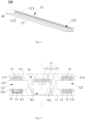
- Figs. 1-5 show a track 100 according to a preferred embodiment of the present application.
- the track 100 is made of rigid material and has a long flat shape, which is used for assembling on an installation foundation and can be coupled with an electrical device 300 through a track adapter 200 to form an electrical system 400, or the electrical device 300 can be coupled with the track 100 through the track adapter 200 to form the electrical system 400 (see Figs. 20 and 27 ).
- the track 100 is made of aluminum alloy material, so that the track 100 has advantages of light weight, strong corrosion resistance and stable chemical properties while having a rigid supporting function.
- the track 100 can also be made of other rigid conductive materials or insulating materials, which is not limited by the present application.
- the track 100 includes a main body 11 and a power supply conductive piece 13 arranged in the main body 11.
- the main body 11 extends along a length direction and includes a width direction and a thickness direction both perpendicular to the length direction, and the main body 11 includes a top wall 111 for assembling with the installation foundation, a bottom wall 112 arranged opposite to the top wall 111, and a left sidewall 113 and a right sidewall 114 both arranged between the top wall 111 and the bottom wall 112.
- the top wall 111 and the bottom wall 112 of the track 100 both extend along the length direction and width direction of the track 100, and the left sidewall 113 and the right sidewall 114 of the track 100 extend along the length direction and thickness direction of the track 100.
- a side of the top wall 111 of the track 100 facing the installation foundation is provided with a plurality of installation holes 1111, and a number of the installation holes 1111 is set according to a length of the track 100, which is not limited by the present application.
- the plurality of installation holes 1111 are uniformly distributed along the length direction of the track 100 for fixing the track 100 on the installation foundation.
- the track 100 of the present application can be a surface-mounted track 100 or a suspension-mounted track 100, which is not limited by the present application.
- the installation foundation can be a ceiling or a wall, and fasteners such as screws pass through the installation holes 1111, and heads of the fasteners are finally pressed on two sides of the installation holes 1111 of the top wall and locked with the installation foundation to fix the track 100 on the installation foundation.
- the track 100 of the present application is used as the suspension-mounted track 100, the track 100 is fixed on the installation foundation through a traction structure.
- both the left sidewall 113 and the right sidewall 114 of the track 100 are recessed in a direction of approaching each other to form a first guide groove 121 and a second guide groove 122 suitable for mechanical connection, that is to say, the track 100 is arranged in an I-shape, and both the left sidewall 113 and the right sidewall 114 of the track 100 are recessed towards an inside of the main body 11 to form the first guide groove 121 and the second guide groove 122.
- the main body 11 includes a central axis perpendicular to the width direction, and the first guide groove 121 and the second guide groove 122 are symmetrically arranged along the central axis and extend along the length direction of the track 100.
- Both the first guide groove 121 and the second guide groove 122 include an opening part 123 away from the central axis and a fixing surface 124 close to the central axis. That is to say, the first guide groove 121 and the second guide groove 122 are both in an inverted U-shape and communicate with the outside, and the opening parts 123 of the first guide groove 121 and the second guide groove 122 are arranged on outer wall surfaces of the left sidewall 113 and the right sidewall 114.
- a first clamping piece 221 and a second clamping piece 222 of a track adapter 200 are inserted into the first guide groove 121 and the second guide groove 122 of the track 100 from the opening parts 123, and are mechanically connected with the track 100, and can slide in the first guide groove 121 and the second guide groove 122 along the length direction of the track 100.
- the track adapter 200 can be connected with the track 100 in a matching way from outer side surfaces of the track 100, thus avoiding the problem in the existing art that the track 100 needs to vertically extend downward to form a guide groove and to get electricity from an inner side, a thickness of the track 100 is effectively reduced and an occupied space of the track 100 is reduced.
- the mechanical connection mode adopting the first guide groove 121 and the second guide groove 122 can avoid the potential safety hazard caused by the falling of the electrical device 300 due to the unstable magnetic connection, and the stability and safety of the connection with the track 100 is improved.
- Both the first guide groove 121 and the second guide groove 122 include an upper surface 125 and a lower surface 126 which are oppositely arranged along the length direction of the main body 11. Extension lengths of the upper surface 125 and the lower surface 126 in the width direction of the main body 11 is longer than a vertical distance between the upper surface 125 and the lower surface 126, so as to increase a contact area between the track 100 and the track adapter 200 and improve the stability and safety of the connection with the track 100.
- At least two power supply conductive pieces 13 are provided, the at least two power supply conductive pieces 13 are in a flat and strip shape, and are a positive electrode and a negative electrode respectively, the at least two power supply conductive pieces 13 are inserted into the main body 11, and peripheral walls of the at least two power supply conductive pieces 13 are wrapped by insulating pieces 15 to play a role of separation and insulation, so as to avoid short circuit in the case that the track 100 is made of conductive materials. In the case that the track 100 is made of insulating materials, the insulating pieces 15 can also be omitted.
- the insulating pieces 15 include openings 151 at the sides facing the first guide groove 121 and the second guide groove 122, so that the power supply conductive piece 13 can be exposed outside of the insulating piece 15 and at least partially exposed in the first guide groove 121 and/or the second guide groove 122.
- both the power supply conductive piece 13 and the insulating piece 15 are arranged on the upper surface 125 and/or the lower surface 126.
- a shape of the insulating piece 15 matches a shape of the power supply conductive piece 13, the insulating piece 15 is wrapped on the peripheral wall of the power supply conductive piece 13, and the insulating piece 15 is provided with an opening 151 at a side of the power supply conductive piece 13 close to the upper surface 125 and/or the lower surface 126, so that the power supply conductive piece 13 is exposed on the upper surface 125 and/or the lower surface 126, and further at least partially exposed in the first guide groove 121 and/or the second guide groove 122.
- the track 100 and the track adapter 200 can be electrically connected while being mechanically connected through the first guide groove 121 and the second guide groove 122, which is convenient and quick.
- four power supply conductive pieces 13 can also be provided, and the four power supply conductive pieces 13 include two positive electrodes and two negative electrodes, which are respectively arranged on the upper surfaces 125 and the lower surfaces 126 of the first guide groove 121 and the second guide groove 122, so that the track 100 has a dual electrical circuit to meet a demand of independent control of two-way output of dimming and toning products in a market trend, and can also be independently controlled for each channel of four wires and three circuits, or a combination of the power supply conductive pieces 13 can also be deleted according to the requirement application of actual circuit.
- the track 100 further includes at least two signal conductive pieces 14, which are in a flat and strip shape, and can be in contact with signal spring pieces 24 on the track adapter 200 to form a control circuit ( Fig. 24 ). Outer peripheral walls of the signal conductive pieces 14 are wrapped with the insulating pieces 15, and a shape of the insulating piece 15 matches a shape of the signal conductive piece 14 to play a role of insulation and separation.
- the insulating piece 15 is provided with an opening 151 at a side of the signal conductive piece 14 close to the upper surface 125 and/or the lower surface 126, so that the signal conductive piece 14 is at least partially exposed on the upper surface 125 and/or the lower surface 126, and then at least partially exposed inside the first guide groove 121 and/or the second guide groove 122, so as to realize intelligent control of the track 100.
- the track 100 includes two power supply conductive pieces 13 and two signal conductive pieces 14, the two power supply conductive pieces 13 and the two signal conductive pieces 14 are staggered along the central axis of the main body 11.
- the two power supply conductive pieces 13 are respectively arranged on the upper surface 125 of the first guide groove 121 and the lower surface 126 of the second guide groove 122.
- the two signal conductive pieces 14 are respectively arranged on the lower surface 126 of the first guide groove 121 and the upper surface 125 of the second guide groove 122.
- the two power supply conductive pieces 13 and the two signal conductive pieces 14 are respectively in contact with the two power supply spring pieces 23 and the two signal spring pieces 24 on the track adapter 200 to form an electrical circuit and a control circuit at the same time.
- the power supply conductive pieces 13 and the signal conductive pieces 14 can also be staggered along the central axis of the main body 11 in other ways, or the signal conductive pieces 14 and the power supply conductive pieces 13 are symmetrically arranged along the central axis of the main body 11, or the signal conductive pieces 14 and the power supply conductive pieces 13 are symmetrically arranged along a direction perpendicular to the central axis.
- both the power supply conductive pieces 13 and the signal conductive pieces 14 can be interchanged left and right or interchanged up and down on the upper surfaces 125 and the lower surfaces 126 of the first guide groove 121 and the second guide groove 122, as long as the electrical circuit and the control circuit can be formed in the case that the track 100 is connected with the track adapter 200.
- both the power supply conductive pieces 13 and the signal conductive pieces 14 are copper bars.
- the copper bars have high conductivity and low cost, which are a good choice for electrical connection.
- the power supply conductive pieces 13 and the signal conductive pieces 14 can also be made of other spring metal materials, and a scope of the present application is not limited in this aspect.
- two power supply conductive pieces 13 and two signal conductive pieces 14 are respectively arranged on the upper surfaces 125 and the lower surfaces 126 of the first guide groove 121 and the second guide groove 122.
- the two power supply conductive pieces 13 and the two signal conductive pieces 14 can respectively realize the electrical circuit and the control circuit with the two power supply spring pieces 23 and the two signal spring pieces 24 on the track adapter 200 ( Fig. 24 ).
- This arrangement can solve the problem that, in the existing art, the power supply conductive pieces 13 are arranged on the fixing surfaces 124 located inside the first guide groove 121 and the second guide groove 122, in the case that four-wire configuration for power supply and control are required, at least two pairs of guide grooves need to be arranged on a vertical surface of the track 100, which makes the track 100 relatively large in size and relatively high in height and affects an overall appearance of the track 100.
- a width of the track 100 is generally 30mm, while a thickness of the track 100 is generally in a range from 20 mm to 30 mm, which makes the track 100 relatively thick and occupies a relatively large area.
- the thickness of the track 100 is less than or equal to 8 mm, and a ratio between the thickness of the track 100 and a width of the track 100 is less than 1/3, which hardly takes up space, thus effectively solving the problem that the track 100 occupies the floor height and improving the present application scope of the track 100.
- the thickness of the track 100 can also be effectively reduced by arranging the four power supply conductive pieces 13 on the upper surfaces 125 and the lower surfaces 126 of the first guide groove 121 and the second guide groove 122, which is not limited by the present application.
- the track 100 further includes a supporting part 16 connecting the top wall 111 and the bottom wall 112 along the thickness (height) direction, and the supporting part 16 is located between the first guide groove 121 and the second guide groove 122 along the width direction, the supporting part 16 is used for supporting the track 100, enhancing an overall strength, and can be used as a basis for arranging a lighting assembly 17.
- the supporting part 16 is provided with an accommodating groove 161 penetrating through the top wall 111 and/or the bottom wall 112, and at least one group of lighting assemblies 17 are arranged in the accommodating groove 161, and the lighting assemblies 17 are arranged between the first guide groove 121 and the second guide groove 122 in the width direction and emit light toward the top wall 111 and/or the bottom wall 112.
- the track 100 can further provide its own auxiliary lighting, avoiding the lack of lighting supplement in a part of the track 100 where a lighting fixture is not installed, effectively utilizing the space of the track 100, improving the lighting environment and lighting effect, and meeting the requirements of zonal lighting.
- the supporting part 16 is provided with the accommodating groove 161 penetrating through the bottom wall 112, and a group of lighting assemblies 17 are arranged in the accommodating groove 161, and the lighting assemblies 17 are arranged between the first guide groove 121 and the second guide groove 122 in the width direction and emit light in a direction toward the bottom wall 112.
- the lighting assembly 17 includes a base plate 171 and a light-emitting piece 172, the base plate 171 extends along the length direction of the track 100 and fixed at a side of the top wall 111 close to the bottom wall 112, and the light-emitting piece 172 arranged at a side of the base plate 171 away from the top wall 111 and emits light toward the bottom wall 112.
- the light-emitting piece 172 is an LED light bead, and the LED light beads are uniformly arranged at the side of the base plate 171 away from the top wall 111 to provide independent illumination for the track 100.
- the lighting assembly 17 can use RGB color light sources to set off the atmosphere.
- the lighting fixtures can provide main lighting, and the lighting assembly 17 can provide auxiliary lighting, so as to effectively use the space of the track, meeting the requirements of zonal lighting, create multi-level light, and improve the user experience.
- the lighting fixtures and lighting assemblies 17 can be controlled separately, or in a lighting environment without special requirements, only auxiliary lighting provided by the lighting assemblies 17 on the track 100 can be used to increase the atmosphere and improve the diversified functions of the track 100.
- the lighting assembly 17 further includes a light-exiting part 173, which is arranged in the accommodating groove 161 close to the bottom wall 112 and is fixedly connected with the supporting part 16.
- the light-exiting part 173 includes a bottom plate 1731 and a side plate 1732 extending from the bottom plate 1731 in a direction close to the top wall 111.
- the supporting part 16 is provided with a clamping groove corresponding to the side plate 1732, and the side plate 1732 extends into the clamping groove to be engaged with the supporting part 16.
- a plane where a lowest point of the light-exiting part 173 is located is flush with a plane where a lowest point of the bottom wall 112 is located, so as to improve the aesthetics of the track 100 without affecting the overall thickness of the track 100, and maintain the ultra-thin structure of the track 100.
- the supporting part 16 may be provided with an accommodating groove 161 penetrating through the top wall 111, a group of lighting assemblies 17 are arranged in the accommodating groove 161, and the lighting assemblies 17 are arranged in the accommodating groove 161 between the first guide groove 121 and the second guide groove 122 in the width direction and emit light in a direction toward the top wall 111.
- a plane where the highest point of the light-exiting part 173 is located is flush with a plane where the highest point of the top wall 111 is located, so as to improve the aesthetics of the track 100 without affecting the overall thickness of the track 100, and maintain the ultra-thin structure of the track 100.
- the supporting part 16 is provided with an accommodating groove 161 penetrating through the top wall 111 and the bottom wall 112, and two groups of lighting assemblies 17 are arranged in the accommodating groove 161, the two groups of lighting assemblies 17 are both arranged between the first guide groove 121 and the second guide groove 122 in the width direction, and are respectively arranged at positions close to the top wall 111 and the bottom wall 112, and emit light in the directions toward the bottom wall 112 and toward the top wall 111 respectively.
- the plane of the highest point of the light-exiting part 173 on the top wall 111 is flush with the plane of the highest point on the top wall 111, and the plane of the lowest point of the light-exiting part 173 on the bottom wall 112 is flush with the plane of the lowest point on the bottom wall 112.
- the light-exiting part 173 can be a diffusion plate or a light guide plate, so that the light-exiting part 173 can evenly and gently diffuse the light irradiated by the light-emitting pieces 172 toward the top wall 111 and/or the bottom wall 112 while blocking the accommodating groove 161, thereby reducing the formation of paragraph-like light spots caused by the spaced arrangement of the light-emitting pieces 172, and meanwhile preventing dust from entering the accommodating groove 161 and affecting the service life of the lighting assembly 17.
- the lighting assembly 17 may further include a light distribution piece (not shown), such as a lens, a reflector, etc.
- a light distribution piece such as a lens, a reflector, etc.
- the lens and/or reflector may be arranged in one-to-one correspondence with the light-emitting pieces 172, or one lens and/or reflector may be shared by a plurality of light-emitting pieces 172, which is not limited by the present application.
- the supporting part 16 is provided with an accommodating groove 161 penetrating through the top wall 111 and the bottom wall 112, and a group of lighting assemblies 17 are arranged in the accommodating groove 161, which are arranged between the first guide groove 121 and the second guide groove 122 in the width direction, and the lighting assemblies 17 are arranged at a position close to the top wall 111, and the light-emitting piece 172 is arranged at the side of the base plate 171 away from the top wall 111 and emits light toward the bottom wall 112, and an annular reflector is arranged in a light-exiting direction of the light-emitting piece 172.
- a central ring of the annular reflector can transmit light, and an annular wall of the reflector around the central ring can reflect light, so that a part of the light emitted by light-emitting piece 172 is exited in the direction toward the bottom wall 112 through the central ring of the reflector, and another part of the light emitted by light-emitting piece 172 is exited in the direction toward the top wall 111 after being reflected by the annular wall of the reflector, therefore, by arranging one group of lighting assemblies 17 in the track 100, the light emitted by the group of lighting assemblies 17 can be exited in the directions toward the top wall 111 and the bottom wall 112 at the same time, thereby improving the aesthetics of the track 100, and maintaining the ultra-thin structure of the track 100 without affecting the overall thickness of the track 100.
- two groups of lighting assemblies 17 can also be arranged in the track 100, and the light distribution pieces are arranged in the accommodating groove 161, so that the two groups of lighting assemblies 17 can emit light in the direction toward the top wall 111 or the bottom wall 112 at the same time, which is not limited in the present application.
- the lighting assembly 17 is integrally formed with the track 100, and the lighting assembly 17 is contained inside the track 100, so that it can provide decorative lighting on the premise of not affecting the use of the track 100, and the overall structure is simple and the shape is beautiful.
- the track 100 further includes end caps 18 arranged at two ends of the main body 11, and the end caps 18 are mechanically connected with the main body 11.
- the supporting part 16 is provided with fixing holes 162, and fasteners pass through the fixing holes 162 to fixedly connect the end caps 18 with the track 100, but the present application is not limited thereto.
- the track 100 further includes a conversion connector 19, the conversion connector 19 is configured to cascade at least two tracks 100, and the at least two tracks 100 are mechanically and electrically connected through the conversion connector 19.
- the tracks 100 are cascaded into different track light groups 1 through conversion connectors 19 to meet more lighting requirements.
- the conversion connector 19 includes an insulating body 191, and a conductive terminal 192 and a butting part 193, the conductive terminal 192 is arranged in the insulating body 191 and partially protrude from the insulating body 191. At least two conductive terminals 192 are provided, the at least two conductive terminals 192 are a positive electrode and a negative electrode respectively, the at least two conductive terminals 192 correspond to the at least two power supply conductive pieces 13 of the track 100.
- the conductive terminals 192 of the conversion connector 19 are arranged on a top surface or a bottom surface of the butting part 193, so that in the case that the butting part 193 extends into the first guide groove 121 and the second guide groove 122 of the at least two tracks 100, the conductive terminals 192 and the power supply conductive pieces 13 are electrically connected. So that the at least two tracks 100 are mechanically and electrically connected through the conductive terminals 192 and the butting part 193 of the conversion connector 19 to form the track light group 1.
- the conversion connectors 19 with different structures are selected to have different structures, so that the structures of the cascaded track light groups 1 are different.
- the structure of the conversion connector 19 includes, but is not limited to, straight-line, T-shaped, cross-shaped, mouth-shaped and L-shaped facades and other structures, so the shape of the track light group 1 can be correspondingly formed into straight-line, T-shaped, cross-shaped, mouth-shaped and L-shaped facades and other shapes, the present application is not limited thereto, so as to meet the diverse needs of users.
- the track 100 can be mechanically and electrically connected with various electrical devices 300 through the conversion connector 19, which improves the present application range of the track 100 and is convenient and reliable.
- the present application provides a track adapter 200 of a preferred embodiment, the track adapter 200 is used to be clamped to the track 100 to realize mechanical connection with the track 100 and electrical connection at the same time.
- the track adapter 200 includes a connection body 21, a first clamping piece 221 and a second clamping piece 222 movably connected with the connection body 21 respectively, a power supply spring piece 23 arranged on the first clamping piece 221 and/or the second clamping piece 222 for electrically connecting with the track 100, and a pressing part 271 positioned between the first clamping piece 221 and the second clamping piece 222 and movably connected with the connection body 21.
- a direction in which the first clamping piece 221 and the second clamping piece 222 move relative to the connection body 21 as a first direction
- a direction perpendicular to the moving direction as a second direction.
- the first clamping piece 221 and the second clamping piece 222 are arranged to face each other from opposite sides of the connection body 21, that is to say, both the first clamping piece 221 and the second clamping piece 222 are arranged in a direction close to the connection body 21, and the first clamping piece 221 and the second clamping piece 222, together with the connection body 21, surround and define an accommodating space 25 for accommodating at least a part of the track 100.
- the accommodating space 25 is generally configured in a convex shape structure, the accommodating space 25 includes a first space 251 and a second space 252 which are communicated with each other.
- the first space 251 is surrounded by a housing 211 of the connection body 21, a third part 225 of the first clamping piece 221 and a third part 225 of the second clamping piece 222.
- the second space 252 is surrounded by a vertical sidewall 2236 of the first clamping piece 221 close to the second clamping piece 222 and a vertical sidewall 2236 of the second clamping piece 222 close to the first clamping piece 221. Because the first clamping piece 221 and the second clamping piece 222 are arranged to face each other, a distance of the second space 252 is smaller than a distance of the first space 251 in the first direction, so that the convex-shaped accommodating space 25 is just matched with the I-shaped track 100.
- first clamping piece 221 and the second clamping piece 222 of the track adapter 200 respectively enter the first guide groove 121 and the second guide groove 122 from the left sidewall 113 and the right sidewall 114 of the track 100, the first clamping piece 221 and the first guide groove 121 are in face-to-face contact, and the second clamping piece 222 and the second guide groove 122 are in face-to-face contact, thus realizing mechanical connection.
- the track adapter 200 can be connected from outsides of the left sidewall 113 and the right sidewall 114 of the track 100, which is convenient for installation, and the track adapter 200 and the track 100 partially overlap in the height direction, thereby reducing a height of the electrical system 400 with the track adapter 200 and the track 100.
- the track adapter 200 is installed outside the track 100, the independent wireless control of the electrical system 400 can be realized, and the technical problem that a traditional track adapter 200 is installed inside a track 100 and the wireless communication signal is weak can be solved.
- the connection body 21 includes a housing 211, the housing 211 includes an upper housing 2111 and a lower housing 2112.
- An installation space 2113 is formed between and surrounded by the upper housing 2111 and the lower housing 2112, and the first clamping piece 221 and the second clamping piece 222 and the pressing part 271 are at least partially accommodated in the installation space 2113.
- a side of the lower housing 2112 close to the upper housing 2111 is provided with four combining parts 212, and the four combining parts 212 are located at four corners of the lower housing 2112.
- Each of the four combining parts 212 includes a first limiting baffle 2121 with an extension direction parallel to the first direction, a second limiting baffle 2122 with an extension direction parallel to the second direction, and a hollow fixing post 2123 located inside the first limiting baffle 2121 and the second limiting baffle 2122.
- the upper housing 2111 is provided with a through hole 2114, and fasteners such as bolts extend into the hollow fixing posts 2123 through the through holes 2114, so that the upper housing 2111 and the lower housing 2112 are fixedly connected through four combining parts 212.
- the first limiting baffle 2121 and the second limiting baffle 2122 are angularly arranged.
- the first limiting baffle 2121 and the second limiting baffle 2122 are integrally formed.
- a distance between two adjacent first limit baffles 2121 is greater than a distance between two ends of the pressing part 271 exposed outside the installation space 2113, but less than a distance between two ends of the pressing part 271 accommodated inside the installation space 2113, thus a movable space is provided for the pressing part 271 to movably connect with the connection body 21 and meanwhile the pressing part 271 is prevented from falling off the connection body 21.
- a distance between two adjacent second limiting baffles 2122 is larger than a distance between two ends of the first clamping piece 221 or the second clamping piece 222 exposed outside the installation space 2113, but smaller than a distance between two ends of the first clamping piece 221 or the second clamping piece 222 accommodated inside the installation space 2113, thus a movable space is provided for the first clamping piece 221 and the second clamping piece 222 to movably connect with the connection body 21 and meanwhile the first clamping piece 221 and the second clamping piece 222 are prevented from falling off the connection body 21.
- the first clamping piece 221 and the second clamping piece 222 are arranged in a U-shape, and both of the first clamping piece 221 and the second clamping piece 222 include a first part 223 located above the connection body 21 for clamping connection with the track 100, a second part 224 movably connected with the connection body 21, and a third part 225 connecting the first part 223 and the second part 224.
- connection body 21 There is a height difference between the first part 223 and the second part 224, which is not less than a thickness of the connection body 21, so that the connection body 21 can be at least partially accommodated in an U-shaped groove formed by the first part 223 and the second part 224, thereby facilitating the movable connection between the connection body 21 and the first clamping piece 221 and the second clamping piece 222.
- the first part 223 is located above the connection body 21, and an orthographic projection of the first part 223 in a thickness direction of the track adapter 200 is located on the connection body 21.
- the first part 223 includes a first abutting surface 2231 close to the connection body 21 and a second abutting surface 2232 away from the connection body 21.
- the power supply spring piece 23 is located between the first abutting surface 2231 and the second abutting surface 2232, and at least partially exposed on the first abutting surface 2231 and/or the second abutting surface 2232 for electrically connecting with the power supply conductive piece 13 on the track 100.
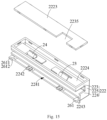
- the first part 223 may be integrally formed with the power supply spring piece 23, or may include an upper cover 2233 and a lower groove body 2234 assembled with the upper cover 2233 in the height direction, and the power supply spring piece 23 is sandwiched between the upper cover 2233 and the lower groove body 2234.
- the first part 223 includes the upper cover 2233 and the lower groove body 2234 assembled with the upper cover 2233 in the height direction.
- a peripheral wall of the upper cover 2233 is provided with a hook
- an inner peripheral wall of the lower groove body 2234 is correspondingly provided with a bayonet, and the hook extends into the bayonet, so that the upper cover 2233 and the lower groove body 2234 are snap-connected.
- the surface of the upper cover 2233 facing away from the lower groove body 2234 is the second abutting surface 2232
- the surface of the lower groove body 2234 facing away from the upper cover 2233 is the first abutting surface 2231.
- the power supply spring piece 23 includes a fixing part 231 and an abutting part 232 which are connected in sequence.
- the fixing part 231 is plate-shaped and accommodated in the gap, and the abutting part 232 protrudes in a direction close to the first abutting surface 2231 or the second abutting surface 2232 to form an inverted V-shaped structure.
- the first abutting surface 2231 and the second abutting surface 2232 are provided with connection openings 2235 at positions corresponding to the abutting part 232.
- the abutting parts 232 are exposed on the first abutting surface 2231 and/or the second abutting surface 2232 through the connection opening 2235, and are in contact with the power supply conductive pieces 13 of the track 100, thereby realizing the electrical connection between the track 100 and the track adapter 200.
- the power supply spring piece 23 can have certain elasticity. In the case that the power supply spring piece 23 passes through the connection opening 2235 and is in contact with the power supply conductive piece 13, the power supply conductive piece 13 exerts a certain force on the power supply spring piece 23, and a restoring force of the power supply spring piece 23 enables the power supply spring piece 23 to better contact with the power supply conductive piece 13, thus realizing reliable electrical connection.
- the gap also provides a deformation space for the elastic deformation of the power supply spring piece 23.
- the inverted V-shaped abutting part 232 also facilitates the reliable deformation of the power supply spring piece 23 in the case that the power supply spring piece 23 is installed and stressed.
- the power supply spring piece 23 may also have other structures, which is not limited by the present application.
- the track adapter 200 further includes the signal spring pieces 24 arranged on the first clamping piece 221 and/or the second clamping piece 222.
- the signal spring pieces 24 pass through the connection openings 2235 in the first abutting surface 2231 and the second abutting surface 2232 and are in contact with the signal conductive pieces 14 on the track 100.
- the signal conductive piece 14 gives a certain force to the signal spring piece 24.
- a restoring force of the signal spring piece 24 enables the signal spring piece 24 to better contact with the signal conductive piece 14, thus realizing reliable signal connection to receive the control signal of the electrical system 400, thus realizing the intelligent control of the electrical system 400.
- the signal spring piece 24 is also arranged on the first part 223, and can be integrally formed with the first part 223 or sandwiched between the upper cover 2233 and the lower groove body 2234.
- the signal spring piece 24 and the power supply spring piece 23 have the same structure, so the details are not repeated here.
- the structures of the signal spring piece 24 and the power supply spring piece 23 may be different, which is not limited by the present application.
- the track adapter 200 includes two power supply spring pieces 23 and two signal spring pieces 24, and the arrangement of the two power supply spring pieces 23 and the two signal spring pieces 24 corresponds to the arrangement of the two power supply conductive pieces 13 and the two signal conductive pieces 14 of the track 100.
- the two power supply conductive pieces 23 and the two signal conductive pieces 24 are staggered along the central axis of the main body 11 of the track 100, that is to say, in the case that the two power supply conductive pieces 13 are respectively arranged on the upper surface 125 of the first guide groove 121 and the lower surface 126 of the second guide groove 122, and two signal conductive pieces 14 are respectively arranged on the lower surface 126 of the first guide groove 121 and the upper surface 125 of the second guide groove 122, the two power supply spring pieces 23 and two signal elastic pieces 24 are also staggered along the central axis of the connection body 21 of the track adapter 200, that is to say, the two power supply spring pieces 23 are respectively exposed on the second abutting surface 2232 of the first clamping piece 221 and the first abutting surface 2231 of the second clamping piece 222, and the two signal spring pieces 24 are respectively exposed on the first abutting surface 2231 of the first clamping piece 221 and the second abutting surface 2232
- the power supply spring piece 23 and the signal spring piece 24 can also be staggered along the central axis of the connection body 21 in other ways, or the signal spring piece 24 and the power supply spring piece 23 are symmetrically arranged along the central axis of the connection body 21, or the signal spring piece 24 and the power supply spring piece 23 are symmetrically arranged along a direction perpendicular to the central axis.
- the power supply spring piece 23 and the signal spring piece 24 follow the installation positions of the power supply conductive piece 13 and the signal conductive member 14, and are interchanged left and right or up and down at the first abutting surfaces 2231 and the second abutment surfaces 2232 of the first clamping piece 221 and the second clamping piece 222, as long as the electrical circuit and the control circuit can be formed when the track 100 is connected with the track adapter 200.
- the power supply spring piece 23 and the signal spring piece 24 are both elastic copper pieces. Under the action of the restoring force of the power supply spring piece 23, the power supply spring piece 23 is in contact with the power supply conductive piece 13 more closely, thus realizing reliable electrical connection. Under the action of the restoring force of the signal spring piece 24, the signal spring piece 24 is in contact with the signal conductive piece 14 more closely, thus realizing reliable signal connection.
- the power supply spring piece 23 and the signal elastic piece 24 exposed outside of the first clamping piece 221 and the second clamping piece 222 on the track adapter 200 are always in contact with the power supply conductive piece 13 and the signal conductive piece 14 exposed in the first guide groove 121 and the second guide groove 122 on the track 100, which will not affect the power supply transmission and the signal transmission between the track adapter 200 and the track 100.
- the power supply spring piece 23 and the signal spring piece 24 can also be made of other elastic metal materials, and the scope disclosed in the present application is not limited in this aspect.
- the track adapter 200 further includes a locking assembly 26 and an unlocking assembly 27, the locking assembly 26 and the unlocking assembly 27 are at least partially accommodated in the installation space 2113 to improve the aesthetics of the track adapter 200.
- the locking assembly 26 is configured to lock and connect the first clamping piece 221 and the second clamping piece 222 with the connection body 21, thereby fixing the track 100 in the accommodating space 25, so that the track adapter 200 and the track 100 remain locked, that is to say, in a relatively static state.
- the unlocking assembly 27 is configured to unlock the locking connection between the first clamping piece 221 and the second clamping piece 222 and the connection body 21, so that the track adapter 200 and the track 100 are released, that is to say, they can slide relatively.
- the locking assembly 26 includes locking parts 261 respectively located on the first clamping part 221 and the second clamping part 222, and an engagement part 2722 located on the unlocking assembly 27.
- the locking part 261 is matched and connected with the engagement part 2722 to lock the track adapter 200 on the track 100.
- the locking part 261 is disposed at a connection end 2241 of the second part 224 close to the connection body 21, and includes a first wall 2611 and a second wall 2612 which are arranged at a folded angle, the first wall 2611 is formed by extending horizontally from an end of the first part 223 to the connection body 21, and the second wall 2612 is formed at a folded angle of 90 degrees downward from an end of the first wall 2611.
- a locking groove for locking the engagement part 2722 is formed between the first wall 2611 and the second wall 2612.
- An inclined guide surface is provided at a side of the second wall 2612 close to the connection body 21 to guide the locking part 261 to connect and lock with the engagement part 2722.
- the locking part 261 can also have other structures, which is not limited by the present application.
- the locking assembly 26 further includes two first elastic members 262, which are symmetrically arranged along the second direction, and elastic directions of the two first elastic members 262 are parallel to the first direction.
- An end of one of the two first elastic members 262 is elastically connected with the first clamping piece 221, and another end of the one is elastically connected with the connection body 21, an end of the other first elastic member 262 is elastically connected with the second clamping piece 222, and another end of the other first elastic member 262 is elastically connected with the connection body 21.
- ends of the first clamping piece 221 and second clamping piece 222 close to the first elastic member 262 are provided with protruding parts 2242, that is to say, the protruding part 2242 is arranged at the connection end 2241 of the second part 224, and a limiting groove 213 for limiting the first elastic member 262 is arranged in the connection body 21, an end of the first elastic member 262 is connected with the protruding part 2242, and another end abuts against the limiting groove 213.
- connection end 2241 is further provided with a first retaining wall 2243 extending in the second direction.
- the first retaining wall 2243 is accommodated in the installation space 2113 and is close to a center of the installation space 2113 relative to the second limiting baffle 2122, so as to prevent the first clamping piece 221 or the second clamping piece 222 from falling off the connection body 21.
- the unlocking assembly 27 is arranged between the first clamping piece 221 and the second clamping piece 222, and is movably connected with the connection body 21, and includes the pressing part 271 and a movable plate 272 extending from a bottom of the pressing part 271 in a direction away from the pressing part 271.
- the pressing part 271 and the movable plate 272 can be integrally arranged or separately arranged and connected by assembly, which is not limited in the present application.
- the pressing part 271 is at least partially accommodated in the installation space 2113, and a second retaining wall 2711 extending in the first direction is provided at an end of the pressing part 271 close to the installation space 2113.
- the second retaining wall 2711 is accommodated in the installation space 2113 and is close to the center of the installation space 2113 relative to the first limiting baffle 2121 to prevent the pressing part 271 from falling off the connection body 21.
- the movable plate 272 is accommodated in the installation space 2113 and can slide in the second direction relative to the lower housing 2112.
- guide parts 214 are provided at positions corresponding to two ends of the movable plate 272, the guide parts 214 extend from the lower housing 2112 to a direction close to the upper housing 2111 and are configured to guide a moving direction of the movable plate 272 in the connection body 21. That is to say, because of the existence of the guide part 214, the movable plate 272 can only slide relative to the lower housing 2112 in the second direction.
- the two guide parts 214 and a baffle 215 located between the guide parts 214 form an accommodating groove 216 for accommodating and limiting the movable plate 272.
- the movable plate 272 includes a yielding part 2721 and the engagement part 2722 which are arranged in sequence from a position close to the pressing part 271 to a position away from the pressing part 271.
- the engagement part 2722 is formed by the movable plate 272 extending in a direction away from the lower housing 2112, and is used for engaging with the locking part 261 to realize the locking connection between the first clamping piece 221 and the second clamping piece 222 and the connection body 21.
- the two engagement parts 2722 move towards each other, thus sliding out of the locking groove.
- the locking part 261 and the engagement part 2722 are released from the locking connection, thereby releasing the locking connection between the first clamping part 221 and the second clamping part 222 and the connection body 21.
- the unlocking assembly 27 further includes second elastic members 273, two second elastic members 273 are provided, the two second elastic members 273 are symmetrically arranged along the first direction, and elastic directions of the two second elastic members 273 are parallel to the second direction.
- An end of each of the two second elastic members 273 is elastically connected with the movable plate 272, and another end of each of the two second elastic members 273 is elastically connected with the connection body 21.
- the movable plate 272 is further provided with a reinforcing plate 2723 extending in parallel with the engagement part 2722, and an end of the reinforcing plate 2723 close to the second elastic member 2733 is provided with a first sleeve joint part 2724.
- connection body 21 is provided with the baffle 215, and a side of the baffle 215 close to the second elastic member 273 is provided with a second sleeve joint part 2151.
- An end of the second elastic member 273 is sleeved on the first sleeve joint part 2724, and another end is sleeved on the second sleeve joint part 2151.
- a distance between the first sleeve joint part 2724 and the second sleeve joint part 2151 is greater than a length of the engagement part 2722.
- the engagement part 2722 has enough moving space, so as to release the locking connection between the first clamping part 221 and the second clamping part 222 and the connection body 21.
- the electrical system 400 includes a track 100, a track adapter 200 and an electrical device 300, and the electrical device 300 is coupled to the track 100 through the track adapter 200.
- the electrical device 300 is a lighting fixture, which is used for accent lighting of a local region.
- the lighting assembly 17 is further arranged in the track 100, so that the electrical system 400 can provide supplementary lighting at a part of the track 100 where no lighting fixture is installed without affecting the use of the track 100, thus improving the lighting environment and lighting effect, effectively utilizing the space of the track 100 and meeting the lighting requirements of the districts.
- the electrical system 400 of the present application has the functions of both main lighting and auxiliary lighting, and the auxiliary lighting makes the whole light transparent, bright and textured.
- the lighting assembly 17 can use RGB color light sources to set off the atmosphere.
- the lighting fixture and the lighting assembly 17 are controlled separately, for example, the lighting fixture is not installed in the lighting environment without special requirements, so as to meet the different use requirements of users and improve the user's experience.
- the electrical system 400 further includes a driving power supply, which can be arranged in the installation foundation to provide appropriate power supply for the track 100 and the electrical system 400 with the track 100 without affecting the aesthetics of the electrical system 400.
- the driving power supply can also be assembled on the track or placed outside the track, which is not limited by the present application.
- the electrical device 300 is only used for illustrative purposes and is not intended to limit the scope of the present application. It is understood by those skilled in the art that the electrical device 300 can be of various types suitable for the installation on the track 100.
- the electrical device 300 can be a power consumption device such as a lighting fixture, a monitoring device, an intelligent control device or a sensor module, and can also be a power supply device such as a driving power supply.
- the present application is not limited thereto.
- the electrical device 300 is a driving power supply, and the driving power supply can also be directly coupled to the track 100, and other electrical device 300, such as the lighting fixture, the monitoring device, the intelligent control device or the sensor module, can be coupled to the driving power supply.
- the driving power supply is integrated with the track adapter 200, that is to say, the driving power supply is arranged in the track adapter 200 to receive the power of the commercial power and convert it into the power required by the other electrical device 300.
- the other electrical device 300 such as lighting fixture, the monitoring device, the intelligent control device or the sensor module, can also be provided with its own driving device to realize power conversion, which is not limited by the present application.
- the lower housing 2112 of the track adapter 200 can further be provided with a connection hole 2115.
- the track adapter 200 further includes a hollow connection rod 28 passing through the connection hole 2115.
- the hollow connection rod 28 is suitable for coupling the electrical device 300.
- wires can be arranged in the hollow connection rod 28 for electrically connecting the track adapter 200 and the electrical device 300. With this arrangement, the electrical device 300 can be easily coupled to the track adapter 200, and the mechanical and electrical connection between the electrical device 300 and the track adapter 200 can be realized.
- the electrical device 300 may be directly connected to the track adapter 200 without additional components interposed between the electrical device 300 and the track adapter 200.
- the electrical system 400 may further include more connection pieces interposed between the electrical device 300 and the track adapter 200, and the scope of the present application is not limited in this aspect.
- the first clamping piece 221 and the second clamping piece 222 of the track adapter 200 extend into the first guide groove 121 and the second guide groove 122 of the track 100 to realize the mechanical connection between the track adapter 200 and the track 100
- the power supply spring piece 23 and the signal elastic piece 24 located on the first clamping piece 221 and the second clamping piece 222 are elastically abutted with the power supply conductive piece 13 and the signal conductive piece 14 located in the first guide groove 121 and the second guide groove 122, respectively, so as to realize the electrical connection between the track adapter 200 and the track 100.
- the electrical system 400 is convenient and quick to install, and the track adapter 200 and the track 100 partially overlap in the thickness direction (i.e., the height direction) of the track 100 when the track adapter 200 and the track 100 are connected, so that a thickness of the electrical system 400 can be effectively reduced and the occupied space of the electrical system 400 can be reduced.
- the locking connection between the first clamping piece 221 and the second clamping piece 222 and the connection body 21 can be released, so that the track 100 can move in the accommodating space 25 of the track adapter 200, that is to say, the locking connection between the track 100 and the track adapter 200 can be released, and the track adapter 200 can slide relative to the track 100.
- a lighting module is integrated in the track adapter 200, thus avoiding coupling the electrical device 300 to the track adapter 200 and reducing the occupied space of the electrical system 400.
- the lighting module can be a grid light or a linear light, etc., which is not limited by the present application.
- the track adapter 200 has a simple structure, by the first clamping piece 221 and the second clamping piece 222 being disposed to face each other, can be mechanically connected and electrically connected with the track 100 from the outer side of the track 100, which is easy and convenient to install, and the stability of the connection between the track adapter 200 and the track 100 is improved, meanwhile, the accommodating space 25 for partially housing the track 100 is formed on the track adapter 200, so that the track 100 and the track adapter 200 can be partially overlapped in the height direction, thus, the height of the track 100 and the track adapter 200 are effectively reduced, and the occupied space thereof is reduced.
Landscapes
- Engineering & Computer Science (AREA)
- General Engineering & Computer Science (AREA)
- Arrangement Of Elements, Cooling, Sealing, Or The Like Of Lighting Devices (AREA)
- Details Of Connecting Devices For Male And Female Coupling (AREA)
Abstract
Description
- The present application claims the priority of
Chinese patent application No.202123410379.8, filed on December 30, 2021 Chinese patent application No.202111661528. X, filed on December 30, 2021 - The present application relates to the technical field of lighting, in particular to a track adapter, a track, and an electrical system.
- Track lamps mainly include tracks (conductive tracks) fixed on a ceiling or wall and various lamps that can slide along the tracks, which can be spotlights, line lights and so on.
- Usually, the track is relatively large in size and relatively high in height, which may occupy high-rise space when used indoors and affect the use effect. Moreover, at present, most of the track lamps in the market are magnetic attraction track lamps, and the lamp body is directly connected with the track by magnetic force. Then, when the lamp body is rotating or swinging, because of the lever principle or shearing force on the magnetic force, the lamp body may fall off or the contact of the power-taking contact may be poor, resulting in potential safety hazards.
- In view of this, it is really needed to provide a track adapter, a track and an electrical system to solve the above problems.
- The purpose of the present application is to provide a track adapter with simple and convenient installation and high connection stability.
- In order to achieve the above purpose, the present application provides a track adapter, configured for coupling an electrical device to a track, and including: a connection body, a first clamping piece and a second clamping piece respectively movably connected to the connection body, and a power supply spring piece provided on the first clamping piece and/or the second clamping piece for electrical connection, wherein the first clamping piece and the second clamping piece are disposed facing each other from opposite sides of the connection body, and the first clamping piece, the second clamping piece and the connection body enclose to form an accommodating space at least partially housing the track.
- As a further improvement of the present application, the first clamping piece and the second clamping piece each include a first abutting surface disposed close to the connection body and a second abutting surface disposed away from the connection body, the power supply spring piece is located between the first abutting surface and the second abutting surface and is at least partially exposed to the first abutting surface and/or the second abutting surface.
- As a further improvement of the present application, a gap is provided between the first abutting surface and the second abutting surface, and the power supply spring piece is at least partially housed within the gap.
- As a further improvement of the present application, the track adapter further includes a signal spring piece provided on the first clamping piece and/or the second clamping piece; the signal spring piece and the power supply spring piece are symmetrically arranged along a central axis of the connection body; or the signal spring piece and the power supply spring piece are staggered along the center axis; or the signal spring piece and the power supply spring piece are symmetrically arranged along a direction perpendicular to the center axis.
- As a further improvement of the present application, the track adapter further includes a locking assembly and an unlocking assembly, the locking assembly is configured to lock and connect the first clamping piece and the second clamping piece with the connection body, and the unlocking assembly is configured to unlock locking connection of the first clamping piece and the second clamping piece with the connection body.
- As a further improvement of the present application, the locking assembly includes locking parts respectively located on the first clamping piece and the second clamping piece, and engagement parts located on the unlocking assembly, wherein the locking parts are matched and connected with the engagement parts to lock the track adapter.
- As a further improvement of the present application, the locking assembly further includes a first elastic member, an end of the first elastic member is elastically connected to the first clamping piece /the second clamping piece, and another end of the first elastic member is elastically connected to the connection body; the first clamping piece /the second clamping piece is provided with a protruding part at an end thereof close to the first elastic member, the connection body is provided with a limiting groove for limiting the first elastic member, an end of the first elastic member is connected with the protruding part, and another end of the first elastic member abuts the limiting groove.
- As a further improvement of the present application, the unlocking assembly is provided between the first clamping piece and the second clamping piece, and is movably connected with the connection body, and the unlocking assembly includes a pressing part and a movable plate extending from a bottom of the pressing part toward a direction away from the pressing part, the movable plate includes a yielding part and an engagement part disposed sequentially from a position close to the pressing part towards a position away from the pressing part.
- As a further improvement of the present application, the unlocking assembly further includes a second elastic member, an end of the second elastic member is elastically connected with the movable plate, and another end of the second elastic member is elastically connected with the connection body; the movable plate is provided with a first sleeve joint part at an end thereof close to the second elastic member, the connection body is provided with a baffle, the baffle is provided with a second sleeve joint part at a side thereof close to the second elastic member, an end of the second elastic member is sleeved on the first sleeve joint part, and another end of the second elastic member is sleeved on the second sleeve joint part.
- As a further improvement of the present application, a distance between the first sleeve joint part and the second sleeve joint part is greater than a length of the engagement part in a moving direction of the movable plate.
- As a further improvement of the present application, a guide part is provided in the connection body at a position corresponding to the movable plate, and the guide part is configured to guide a moving direction of the movable plate in the connection body.
- As a further improvement of the present application, the connection body includes a housing and an installation space enclosed by the housing, the locking assembly and the unlocking assembly are at least partially housed within the installation space.
- As a further improvement of the present application, a connection hole is provided at a bottom of the housing, the track adapter further includes a hollow connection rod passing through the connection hole, the hollow connection rod is configured to couple to the electrical device.
- The second purpose of the present application is to provide a track matched and connected with the abovementioned track adapter.
- In order to achieve the above purpose, the present application provides a track, and the track is configured to be mechanically connected and electrically connected with the abovementioned track adapter.
- The third purpose of the present application is to provide an electrical system including the abovementioned track adapter.
- In order to achieve the above purpose, the present application provides an electrical system, including the abovementioned track adapter; the electrical system further includes a track and an electrical device, wherein the electrical device is coupled to the track through the track adapter.
- The present application has the following beneficial effect: compared with the existing art, the track adapter of present application can be mechanically connected and electrically connected with the track from the outer side of the track through the first clamping piece and the second clamping piece that are disposed to face each other, the installation is easy and convenient, the stability of the connection between the track adapter and the track is improved, meanwhile, the accommodating space for partially housing the track is formed on the track adapter, so that the track and the track adapter can be partially overlapped in the height direction, thereby effectively reducing the height of the track and the track adapter, and reducing the occupied space thereof.
- Hereinafter, the technical scheme and other beneficial effects of the present application will be obvious by describing the specific embodiments of the present application in detail with the attached drawings.
-
Fig. 1 is a perspective view of a track according to a preferred embodiment of the present application. -
Fig. 2 is a sectional view ofFig. 1 -
Fig. 3 is a perspective view from another angle ofFig. 1 . -
Fig. 4 is a sectional view of a first installation mode ofFig. 1 . -
Fig. 5 is a sectional view of a second installation mode ofFig. 1 . -
Fig. 6 is a perspective view of an adapter according to a preferred embodiment of the present application. -
Fig. 7 is a perspective view of a track light group according to a first preferred embodiment of the present application. -
Fig. 8 is a perspective view of a track light group according to a second preferred embodiment of the present application. -
Fig. 9 is a perspective view of a track light group according to a third preferred embodiment of the present application. -
Fig. 10 is a perspective view of a track light group according to a fourth preferred embodiment of the present application. -
Fig. 9 is a perspective view of a track light group according to a fifth preferred embodiment of the present application. -
Fig. 12 is a perspective view of a track adapter according to a preferred embodiment of the present application. -
Fig. 13 is a top view ofFig. 12 with an upper housing removed. -
Fig. 14 is an exploded view of a structure ofFig. 12 . -
Fig. 15 is an exploded view of a structure of a second clamping piece inFig. 14 . -
Fig. 16 is a perspective view of a power supply spring piece inFig. 14 -
Fig. 17 is a perspective view of an unlocking assembly inFig. 14 . -
Fig. 18 is a partial structural perspective view of a connection body inFig. 14 . -
Fig. 19 is a sectional view ofFig. 12 . -
Fig. 20 is a perspective view of an electrical system of the first preferred embodiment of the present application. -
Fig. 21 is a side view ofFig. 20 . -
Fig. 22 is an exploded view of a structure ofFig. 20 . -
Fig. 23 is a sectional view ofFig. 20 . -
Fig. 24 is a partial structural sectional view ofFig. 20 . -
Fig. 25 is a schematic view of an unlocked state of the electrical system ofFig. 20 . -
Fig. 26 is a schematic view of a locking state of the electrical system ofFig. 20 . -
Fig. 27 is a perspective view of an electrical system of the second preferred embodiment of the present application. -
- 100-track,
- 1-track light group, 11-main body, 111-top wall, 1111-installation hole, 1112-traction structure, 112-bottom wall, 113-left sidewall, 114-right sidewall, 121-first guide groove, 122-second guide groove, 123-opening part, 124-fixing surface, 125-upper surface, 126-lower surface, 13-power supply conductive piece, 14-signal conductive piece, 15-insulating piece, 151-opening, 16-supporting part, 161-accommodating groove, 162-fixing hole, 17-lighting assembly, 171-base plate, 172-light-emitting piece, 173-light-exiting part, 1731-bottom plate, 1732-side plate, 18-end cap, 19- conversion connector, 191-insulating body, 192-conductive terminal, 193-butting part,
- 200-track adapter,
- 21-connection body, 211-housing, 2111-upper housing, 2112-lower housing, 2113-installation space, 2114-through hole, 2115-connection hole, 212-combining part, 2121-first limiting baffle, 2122- second limiting baffle, 2123-hollow fixing post, 213-limiting groove, 214-guide part, 215-baffle, 2151-second sleeve joint part, 216-accommodating groove, 221-first clamping piece, 222-second clamping piece, 223-first part, 2231-first abutting surface, 2232-second abutting surface, 2233-upper cover, 2234-lower groove body, 2235-connection opening, 2236-vertical sidewall, 224-second part, 2241-connection end, 2242-protruding part, 2243-first retaining wall, 225-third part, 23-power supply spring piece, 231-fixing part, 232-abutting part, 24-signal spring piece, 25-accommodating space, 251-first space, 252-second space, 26-locking assembly, 261-locking part, 2611-first wall, 2612-second wall, 262-first elastic member, 27-unlocking assembly, 271-pressing part, 2711-second retaining wall, 272-movable plate, 2721-yielding part, 2722-engagement part, 2723-reinforcing plate, 2724-first sleeve joint part, 273-second elastic member, 28-hollow connection rod,
- 300-electrical device,
- 400-electrical system.
- In order to make the purpose, technical solution and advantages of the present application more clear, the application will be described in detail with the attached drawings and specific embodiments.
- Here, it should be noted that, in order to avoid obscuring the present application with unnecessary details, only the structure and/or processing steps closely related to the technical solution of the present application are shown in the attached drawings, while other details that are not related to the present application are omitted.
- In addition, it should be noted that the terms "including", "including" or any other variation thereof are intended to cover non-exclusive inclusion, so that a process, method, article or equipment including a series of elements includes not only those elements, but also other elements not explicitly listed, or elements inherent to such process, method, article or equipment.
- Please refer to
Figs. 1-5 , which show atrack 100 according to a preferred embodiment of the present application. Thetrack 100 is made of rigid material and has a long flat shape, which is used for assembling on an installation foundation and can be coupled with anelectrical device 300 through atrack adapter 200 to form anelectrical system 400, or theelectrical device 300 can be coupled with thetrack 100 through thetrack adapter 200 to form the electrical system 400 (seeFigs. 20 and27 ). In this embodiment, thetrack 100 is made of aluminum alloy material, so that thetrack 100 has advantages of light weight, strong corrosion resistance and stable chemical properties while having a rigid supporting function. In other embodiments, thetrack 100 can also be made of other rigid conductive materials or insulating materials, which is not limited by the present application. - The
track 100 includes amain body 11 and a power supplyconductive piece 13 arranged in themain body 11. Themain body 11 extends along a length direction and includes a width direction and a thickness direction both perpendicular to the length direction, and themain body 11 includes atop wall 111 for assembling with the installation foundation, abottom wall 112 arranged opposite to thetop wall 111, and aleft sidewall 113 and aright sidewall 114 both arranged between thetop wall 111 and thebottom wall 112. Thetop wall 111 and thebottom wall 112 of thetrack 100 both extend along the length direction and width direction of thetrack 100, and theleft sidewall 113 and theright sidewall 114 of thetrack 100 extend along the length direction and thickness direction of thetrack 100. - A side of the
top wall 111 of thetrack 100 facing the installation foundation is provided with a plurality ofinstallation holes 1111, and a number of the installation holes 1111 is set according to a length of thetrack 100, which is not limited by the present application. The plurality ofinstallation holes 1111 are uniformly distributed along the length direction of thetrack 100 for fixing thetrack 100 on the installation foundation. Alternatively, thetrack 100 of the present application can be a surface-mountedtrack 100 or a suspension-mountedtrack 100, which is not limited by the present application. In the case that thetrack 100 of the present application is used as the surface-mountedtrack 100, the installation foundation can be a ceiling or a wall, and fasteners such as screws pass through the installation holes 1111, and heads of the fasteners are finally pressed on two sides of theinstallation holes 1111 of the top wall and locked with the installation foundation to fix thetrack 100 on the installation foundation. In the case that thetrack 100 of the present application is used as the suspension-mountedtrack 100, thetrack 100 is fixed on the installation foundation through a traction structure. - Please continue to refer to
Figs. 1-5 in conjunction withFigs. 20-24 , both theleft sidewall 113 and theright sidewall 114 of thetrack 100 are recessed in a direction of approaching each other to form afirst guide groove 121 and asecond guide groove 122 suitable for mechanical connection, that is to say, thetrack 100 is arranged in an I-shape, and both theleft sidewall 113 and theright sidewall 114 of thetrack 100 are recessed towards an inside of themain body 11 to form thefirst guide groove 121 and thesecond guide groove 122. Themain body 11 includes a central axis perpendicular to the width direction, and thefirst guide groove 121 and thesecond guide groove 122 are symmetrically arranged along the central axis and extend along the length direction of thetrack 100. - Both the
first guide groove 121 and thesecond guide groove 122 include anopening part 123 away from the central axis and a fixingsurface 124 close to the central axis. That is to say, thefirst guide groove 121 and thesecond guide groove 122 are both in an inverted U-shape and communicate with the outside, and the openingparts 123 of thefirst guide groove 121 and thesecond guide groove 122 are arranged on outer wall surfaces of theleft sidewall 113 and theright sidewall 114. Afirst clamping piece 221 and asecond clamping piece 222 of atrack adapter 200 are inserted into thefirst guide groove 121 and thesecond guide groove 122 of thetrack 100 from the openingparts 123, and are mechanically connected with thetrack 100, and can slide in thefirst guide groove 121 and thesecond guide groove 122 along the length direction of thetrack 100. With this arrangement, thetrack adapter 200 can be connected with thetrack 100 in a matching way from outer side surfaces of thetrack 100, thus avoiding the problem in the existing art that thetrack 100 needs to vertically extend downward to form a guide groove and to get electricity from an inner side, a thickness of thetrack 100 is effectively reduced and an occupied space of thetrack 100 is reduced. Meanwhile, the mechanical connection mode adopting thefirst guide groove 121 and thesecond guide groove 122 can avoid the potential safety hazard caused by the falling of theelectrical device 300 due to the unstable magnetic connection, and the stability and safety of the connection with thetrack 100 is improved. - Both the
first guide groove 121 and thesecond guide groove 122 include anupper surface 125 and alower surface 126 which are oppositely arranged along the length direction of themain body 11. Extension lengths of theupper surface 125 and thelower surface 126 in the width direction of themain body 11 is longer than a vertical distance between theupper surface 125 and thelower surface 126, so as to increase a contact area between thetrack 100 and thetrack adapter 200 and improve the stability and safety of the connection with thetrack 100. - At least two power supply
conductive pieces 13 are provided, the at least two power supplyconductive pieces 13 are in a flat and strip shape, and are a positive electrode and a negative electrode respectively, the at least two power supplyconductive pieces 13 are inserted into themain body 11, and peripheral walls of the at least two power supplyconductive pieces 13 are wrapped by insulatingpieces 15 to play a role of separation and insulation, so as to avoid short circuit in the case that thetrack 100 is made of conductive materials. In the case that thetrack 100 is made of insulating materials, the insulatingpieces 15 can also be omitted. The insulatingpieces 15 includeopenings 151 at the sides facing thefirst guide groove 121 and thesecond guide groove 122, so that the power supplyconductive piece 13 can be exposed outside of the insulatingpiece 15 and at least partially exposed in thefirst guide groove 121 and/or thesecond guide groove 122. Preferably, both the power supplyconductive piece 13 and the insulatingpiece 15 are arranged on theupper surface 125 and/or thelower surface 126. A shape of the insulatingpiece 15 matches a shape of the power supplyconductive piece 13, the insulatingpiece 15 is wrapped on the peripheral wall of the power supplyconductive piece 13, and the insulatingpiece 15 is provided with anopening 151 at a side of the power supplyconductive piece 13 close to theupper surface 125 and/or thelower surface 126, so that the power supplyconductive piece 13 is exposed on theupper surface 125 and/or thelower surface 126, and further at least partially exposed in thefirst guide groove 121 and/or thesecond guide groove 122. With this arrangement, thetrack 100 and thetrack adapter 200 can be electrically connected while being mechanically connected through thefirst guide groove 121 and thesecond guide groove 122, which is convenient and quick. - In an alternative embodiment, four power supply
conductive pieces 13 can also be provided, and the four power supplyconductive pieces 13 include two positive electrodes and two negative electrodes, which are respectively arranged on theupper surfaces 125 and thelower surfaces 126 of thefirst guide groove 121 and thesecond guide groove 122, so that thetrack 100 has a dual electrical circuit to meet a demand of independent control of two-way output of dimming and toning products in a market trend, and can also be independently controlled for each channel of four wires and three circuits, or a combination of the power supplyconductive pieces 13 can also be deleted according to the requirement application of actual circuit. - Further, in order to improve an intelligence of the
electrical system 400 with thetrack 100, thetrack 100 further includes at least two signalconductive pieces 14, which are in a flat and strip shape, and can be in contact withsignal spring pieces 24 on thetrack adapter 200 to form a control circuit (Fig. 24 ). Outer peripheral walls of the signalconductive pieces 14 are wrapped with the insulatingpieces 15, and a shape of the insulatingpiece 15 matches a shape of the signalconductive piece 14 to play a role of insulation and separation. The insulatingpiece 15 is provided with anopening 151 at a side of the signalconductive piece 14 close to theupper surface 125 and/or thelower surface 126, so that the signalconductive piece 14 is at least partially exposed on theupper surface 125 and/or thelower surface 126, and then at least partially exposed inside thefirst guide groove 121 and/or thesecond guide groove 122, so as to realize intelligent control of thetrack 100. - In an alternative embodiment, the
track 100 includes two power supplyconductive pieces 13 and two signalconductive pieces 14, the two power supplyconductive pieces 13 and the two signalconductive pieces 14 are staggered along the central axis of themain body 11. For example, the two power supplyconductive pieces 13 are respectively arranged on theupper surface 125 of thefirst guide groove 121 and thelower surface 126 of thesecond guide groove 122. The two signalconductive pieces 14 are respectively arranged on thelower surface 126 of thefirst guide groove 121 and theupper surface 125 of thesecond guide groove 122. In the case that thetrack adapter 200 is connected with thetrack 100, the two power supplyconductive pieces 13 and the two signalconductive pieces 14 are respectively in contact with the two powersupply spring pieces 23 and the twosignal spring pieces 24 on thetrack adapter 200 to form an electrical circuit and a control circuit at the same time. It can be known that the power supplyconductive pieces 13 and the signalconductive pieces 14 can also be staggered along the central axis of themain body 11 in other ways, or the signalconductive pieces 14 and the power supplyconductive pieces 13 are symmetrically arranged along the central axis of themain body 11, or the signalconductive pieces 14 and the power supplyconductive pieces 13 are symmetrically arranged along a direction perpendicular to the central axis. In other words, the power supplyconductive pieces 13 and the signalconductive pieces 14 can be interchanged left and right or interchanged up and down on theupper surfaces 125 and thelower surfaces 126 of thefirst guide groove 121 and thesecond guide groove 122, as long as the electrical circuit and the control circuit can be formed in the case that thetrack 100 is connected with thetrack adapter 200. In this embodiment, both the power supplyconductive pieces 13 and the signalconductive pieces 14 are copper bars. The copper bars have high conductivity and low cost, which are a good choice for electrical connection. In other embodiments, the power supplyconductive pieces 13 and the signalconductive pieces 14 can also be made of other spring metal materials, and a scope of the present application is not limited in this aspect. - In a case of four-wire configuration for power supply and control, two power supply
conductive pieces 13 and two signalconductive pieces 14 are respectively arranged on theupper surfaces 125 and thelower surfaces 126 of thefirst guide groove 121 and thesecond guide groove 122. In the case that thetrack 100 is mechanically connected with thetrack adapter 200, the two power supplyconductive pieces 13 and the two signalconductive pieces 14 can respectively realize the electrical circuit and the control circuit with the two powersupply spring pieces 23 and the twosignal spring pieces 24 on the track adapter 200 (Fig. 24 ). This arrangement can solve the problem that, in the existing art, the power supplyconductive pieces 13 are arranged on the fixing surfaces 124 located inside thefirst guide groove 121 and thesecond guide groove 122, in the case that four-wire configuration for power supply and control are required, at least two pairs of guide grooves need to be arranged on a vertical surface of thetrack 100, which makes thetrack 100 relatively large in size and relatively high in height and affects an overall appearance of thetrack 100. In the existing art, in order to meet the case of four-wire configuration for power supply and control, a width of thetrack 100 is generally 30mm, while a thickness of thetrack 100 is generally in a range from 20 mm to 30 mm, which makes thetrack 100 relatively thick and occupies a relatively large area. In this embodiment, under the condition of satisfying the use of power supply and control and without changing a width of thetrack 100, the thickness of thetrack 100 is less than or equal to 8 mm, and a ratio between the thickness of thetrack 100 and a width of thetrack 100 is less than 1/3, which hardly takes up space, thus effectively solving the problem that thetrack 100 occupies the floor height and improving the present application scope of thetrack 100. As a variation, in the case that four power supplyconductive pieces 13 form at least two power supply circuits, the thickness of thetrack 100 can also be effectively reduced by arranging the four power supplyconductive pieces 13 on theupper surfaces 125 and thelower surfaces 126 of thefirst guide groove 121 and thesecond guide groove 122, which is not limited by the present application. - Further, the
track 100 further includes a supportingpart 16 connecting thetop wall 111 and thebottom wall 112 along the thickness (height) direction, and the supportingpart 16 is located between thefirst guide groove 121 and thesecond guide groove 122 along the width direction, the supportingpart 16 is used for supporting thetrack 100, enhancing an overall strength, and can be used as a basis for arranging alighting assembly 17. The supportingpart 16 is provided with anaccommodating groove 161 penetrating through thetop wall 111 and/or thebottom wall 112, and at least one group oflighting assemblies 17 are arranged in theaccommodating groove 161, and thelighting assemblies 17 are arranged between thefirst guide groove 121 and thesecond guide groove 122 in the width direction and emit light toward thetop wall 111 and/or thebottom wall 112. With this arrangement, under the premise of not affecting the use of thetrack 100, thetrack 100 can further provide its own auxiliary lighting, avoiding the lack of lighting supplement in a part of thetrack 100 where a lighting fixture is not installed, effectively utilizing the space of thetrack 100, improving the lighting environment and lighting effect, and meeting the requirements of zonal lighting. - In an alternative embodiment, the supporting
part 16 is provided with theaccommodating groove 161 penetrating through thebottom wall 112, and a group oflighting assemblies 17 are arranged in theaccommodating groove 161, and thelighting assemblies 17 are arranged between thefirst guide groove 121 and thesecond guide groove 122 in the width direction and emit light in a direction toward thebottom wall 112. Thelighting assembly 17 includes abase plate 171 and a light-emittingpiece 172, thebase plate 171 extends along the length direction of thetrack 100 and fixed at a side of thetop wall 111 close to thebottom wall 112, and the light-emittingpiece 172 arranged at a side of thebase plate 171 away from thetop wall 111 and emits light toward thebottom wall 112. Preferably, the light-emittingpiece 172 is an LED light bead, and the LED light beads are uniformly arranged at the side of thebase plate 171 away from thetop wall 111 to provide independent illumination for thetrack 100. Optionally, thelighting assembly 17 can use RGB color light sources to set off the atmosphere. - In the case that the
first guide groove 121 and thesecond guide groove 122 of thetrack 100 are coupled with lighting fixtures, the lighting fixtures can provide main lighting, and thelighting assembly 17 can provide auxiliary lighting, so as to effectively use the space of the track, meeting the requirements of zonal lighting, create multi-level light, and improve the user experience. The lighting fixtures andlighting assemblies 17 can be controlled separately, or in a lighting environment without special requirements, only auxiliary lighting provided by thelighting assemblies 17 on thetrack 100 can be used to increase the atmosphere and improve the diversified functions of thetrack 100. - The
lighting assembly 17 further includes a light-exitingpart 173, which is arranged in theaccommodating groove 161 close to thebottom wall 112 and is fixedly connected with the supportingpart 16. The light-exitingpart 173 includes abottom plate 1731 and aside plate 1732 extending from thebottom plate 1731 in a direction close to thetop wall 111. The supportingpart 16 is provided with a clamping groove corresponding to theside plate 1732, and theside plate 1732 extends into the clamping groove to be engaged with the supportingpart 16. A plane where a lowest point of the light-exitingpart 173 is located is flush with a plane where a lowest point of thebottom wall 112 is located, so as to improve the aesthetics of thetrack 100 without affecting the overall thickness of thetrack 100, and maintain the ultra-thin structure of thetrack 100. - As a variation, the supporting
part 16 may be provided with anaccommodating groove 161 penetrating through thetop wall 111, a group oflighting assemblies 17 are arranged in theaccommodating groove 161, and thelighting assemblies 17 are arranged in theaccommodating groove 161 between thefirst guide groove 121 and thesecond guide groove 122 in the width direction and emit light in a direction toward thetop wall 111. In this case, a plane where the highest point of the light-exitingpart 173 is located is flush with a plane where the highest point of thetop wall 111 is located, so as to improve the aesthetics of thetrack 100 without affecting the overall thickness of thetrack 100, and maintain the ultra-thin structure of thetrack 100. Or, the supportingpart 16 is provided with anaccommodating groove 161 penetrating through thetop wall 111 and thebottom wall 112, and two groups oflighting assemblies 17 are arranged in theaccommodating groove 161, the two groups oflighting assemblies 17 are both arranged between thefirst guide groove 121 and thesecond guide groove 122 in the width direction, and are respectively arranged at positions close to thetop wall 111 and thebottom wall 112, and emit light in the directions toward thebottom wall 112 and toward thetop wall 111 respectively. In this case, there are two light-exitingparts 173, which are respectively arranged in theaccommodating groove 161 close to thetop wall 111 and thebottom wall 112 and are fixedly connected with the supportingpart 16. The plane of the highest point of the light-exitingpart 173 on thetop wall 111 is flush with the plane of the highest point on thetop wall 111, and the plane of the lowest point of the light-exitingpart 173 on thebottom wall 112 is flush with the plane of the lowest point on thebottom wall 112. - The light-exiting
part 173 can be a diffusion plate or a light guide plate, so that the light-exitingpart 173 can evenly and gently diffuse the light irradiated by the light-emittingpieces 172 toward thetop wall 111 and/or thebottom wall 112 while blocking theaccommodating groove 161, thereby reducing the formation of paragraph-like light spots caused by the spaced arrangement of the light-emittingpieces 172, and meanwhile preventing dust from entering theaccommodating groove 161 and affecting the service life of thelighting assembly 17. - Optionally, the
lighting assembly 17 may further include a light distribution piece (not shown), such as a lens, a reflector, etc. The lens and/or reflector may be arranged in one-to-one correspondence with the light-emittingpieces 172, or one lens and/or reflector may be shared by a plurality of light-emittingpieces 172, which is not limited by the present application. - In an alternative embodiment, the supporting
part 16 is provided with anaccommodating groove 161 penetrating through thetop wall 111 and thebottom wall 112, and a group oflighting assemblies 17 are arranged in theaccommodating groove 161, which are arranged between thefirst guide groove 121 and thesecond guide groove 122 in the width direction, and thelighting assemblies 17 are arranged at a position close to thetop wall 111, and the light-emittingpiece 172 is arranged at the side of thebase plate 171 away from thetop wall 111 and emits light toward thebottom wall 112, and an annular reflector is arranged in a light-exiting direction of the light-emittingpiece 172. A central ring of the annular reflector can transmit light, and an annular wall of the reflector around the central ring can reflect light, so that a part of the light emitted by light-emittingpiece 172 is exited in the direction toward thebottom wall 112 through the central ring of the reflector, and another part of the light emitted by light-emittingpiece 172 is exited in the direction toward thetop wall 111 after being reflected by the annular wall of the reflector, therefore, by arranging one group oflighting assemblies 17 in thetrack 100, the light emitted by the group oflighting assemblies 17 can be exited in the directions toward thetop wall 111 and thebottom wall 112 at the same time, thereby improving the aesthetics of thetrack 100, and maintaining the ultra-thin structure of thetrack 100 without affecting the overall thickness of thetrack 100. - As a variation, two groups of
lighting assemblies 17 can also be arranged in thetrack 100, and the light distribution pieces are arranged in theaccommodating groove 161, so that the two groups oflighting assemblies 17 can emit light in the direction toward thetop wall 111 or thebottom wall 112 at the same time, which is not limited in the present application. - Further, the
lighting assembly 17 is integrally formed with thetrack 100, and thelighting assembly 17 is contained inside thetrack 100, so that it can provide decorative lighting on the premise of not affecting the use of thetrack 100, and the overall structure is simple and the shape is beautiful. - Further, the
track 100 further includes end caps 18 arranged at two ends of themain body 11, and the end caps 18 are mechanically connected with themain body 11. Optionally, the supportingpart 16 is provided with fixingholes 162, and fasteners pass through the fixingholes 162 to fixedly connect the end caps 18 with thetrack 100, but the present application is not limited thereto. By arranging theend cap 18, the aesthetics of thetrack 100 can be improved, and meanwhile, the performance of thelighting assembly 17 in thetrack 100 can be prevented from being affected by dust entering theaccommodating groove 161. - Please refer to
Figs. 6-11 , thetrack 100 further includes aconversion connector 19, theconversion connector 19 is configured to cascade at least twotracks 100, and the at least twotracks 100 are mechanically and electrically connected through theconversion connector 19. Thetracks 100 are cascaded into differenttrack light groups 1 throughconversion connectors 19 to meet more lighting requirements. - Further, the
conversion connector 19 includes an insulatingbody 191, and aconductive terminal 192 and abutting part 193, theconductive terminal 192 is arranged in the insulatingbody 191 and partially protrude from the insulatingbody 191. At least twoconductive terminals 192 are provided, the at least twoconductive terminals 192 are a positive electrode and a negative electrode respectively, the at least twoconductive terminals 192 correspond to the at least two power supplyconductive pieces 13 of thetrack 100. Because the at least two power supplyconductive pieces 13 of thetrack 100 are located on theupper surfaces 125 and thelower surfaces 126 of thefirst guide groove 121 and/or thesecond guide groove 122, correspondingly, theconductive terminals 192 of theconversion connector 19 are arranged on a top surface or a bottom surface of the buttingpart 193, so that in the case that the buttingpart 193 extends into thefirst guide groove 121 and thesecond guide groove 122 of the at least twotracks 100, theconductive terminals 192 and the power supplyconductive pieces 13 are electrically connected. So that the at least twotracks 100 are mechanically and electrically connected through theconductive terminals 192 and the buttingpart 193 of theconversion connector 19 to form thetrack light group 1. - According to the requirements of the required
track light group 1, theconversion connectors 19 with different structures are selected to have different structures, so that the structures of the cascadedtrack light groups 1 are different. Optionally, the structure of theconversion connector 19 includes, but is not limited to, straight-line, T-shaped, cross-shaped, mouth-shaped and L-shaped facades and other structures, so the shape of thetrack light group 1 can be correspondingly formed into straight-line, T-shaped, cross-shaped, mouth-shaped and L-shaped facades and other shapes, the present application is not limited thereto, so as to meet the diverse needs of users. Alternatively, thetrack 100 can be mechanically and electrically connected with variouselectrical devices 300 through theconversion connector 19, which improves the present application range of thetrack 100 and is convenient and reliable. - Please refer to
Figs. 12-19 in conjunction withFigs. 20-26 , the present application provides atrack adapter 200 of a preferred embodiment, thetrack adapter 200 is used to be clamped to thetrack 100 to realize mechanical connection with thetrack 100 and electrical connection at the same time. - The
track adapter 200 includes aconnection body 21, afirst clamping piece 221 and asecond clamping piece 222 movably connected with theconnection body 21 respectively, a powersupply spring piece 23 arranged on thefirst clamping piece 221 and/or thesecond clamping piece 222 for electrically connecting with thetrack 100, and apressing part 271 positioned between thefirst clamping piece 221 and thesecond clamping piece 222 and movably connected with theconnection body 21. Define a direction in which thefirst clamping piece 221 and thesecond clamping piece 222 move relative to theconnection body 21 as a first direction, and a direction perpendicular to the moving direction as a second direction. - The
first clamping piece 221 and thesecond clamping piece 222 are arranged to face each other from opposite sides of theconnection body 21, that is to say, both thefirst clamping piece 221 and thesecond clamping piece 222 are arranged in a direction close to theconnection body 21, and thefirst clamping piece 221 and thesecond clamping piece 222, together with theconnection body 21, surround and define anaccommodating space 25 for accommodating at least a part of thetrack 100. Theaccommodating space 25 is generally configured in a convex shape structure, theaccommodating space 25 includes afirst space 251 and asecond space 252 which are communicated with each other. Thefirst space 251 is surrounded by ahousing 211 of theconnection body 21, athird part 225 of thefirst clamping piece 221 and athird part 225 of thesecond clamping piece 222. Thesecond space 252 is surrounded by avertical sidewall 2236 of thefirst clamping piece 221 close to thesecond clamping piece 222 and avertical sidewall 2236 of thesecond clamping piece 222 close to thefirst clamping piece 221. Because thefirst clamping piece 221 and thesecond clamping piece 222 are arranged to face each other, a distance of thesecond space 252 is smaller than a distance of thefirst space 251 in the first direction, so that the convex-shapedaccommodating space 25 is just matched with the I-shapedtrack 100. - In the case that the
first clamping piece 221 and thesecond clamping piece 222 of thetrack adapter 200 respectively enter thefirst guide groove 121 and thesecond guide groove 122 from theleft sidewall 113 and theright sidewall 114 of thetrack 100, thefirst clamping piece 221 and thefirst guide groove 121 are in face-to-face contact, and thesecond clamping piece 222 and thesecond guide groove 122 are in face-to-face contact, thus realizing mechanical connection. The powersupply spring pieces 23 located on thefirst clamping piece 221 and/or thesecond clamping piece 222 elastically abut against the power supplyconductive pieces 13 located in thefirst guide groove 121 and/or thesecond guide groove 122 to realize electrical connection, in this case, the relatively widebottom wall 112 of thetrack 100 is accommodated in the relatively largefirst space 251, and the relatively narrow supportingpart 16 is at least partially accommodated in the relatively smallsecond space 252. With this arrangement, thetrack adapter 200 can be connected from outsides of theleft sidewall 113 and theright sidewall 114 of thetrack 100, which is convenient for installation, and thetrack adapter 200 and thetrack 100 partially overlap in the height direction, thereby reducing a height of theelectrical system 400 with thetrack adapter 200 and thetrack 100. Meanwhile, because thetrack adapter 200 is installed outside thetrack 100, the independent wireless control of theelectrical system 400 can be realized, and the technical problem that atraditional track adapter 200 is installed inside atrack 100 and the wireless communication signal is weak can be solved. - The
connection body 21 includes ahousing 211, thehousing 211 includes anupper housing 2111 and alower housing 2112. Aninstallation space 2113 is formed between and surrounded by theupper housing 2111 and thelower housing 2112, and thefirst clamping piece 221 and thesecond clamping piece 222 and thepressing part 271 are at least partially accommodated in theinstallation space 2113. Optionally, a side of thelower housing 2112 close to theupper housing 2111 is provided with four combiningparts 212, and the four combiningparts 212 are located at four corners of thelower housing 2112. Each of the four combiningparts 212 includes a first limitingbaffle 2121 with an extension direction parallel to the first direction, a second limiting baffle 2122 with an extension direction parallel to the second direction, and a hollow fixing post 2123 located inside the first limitingbaffle 2121 and the second limiting baffle 2122. Theupper housing 2111 is provided with a throughhole 2114, and fasteners such as bolts extend into the hollow fixing posts 2123 through the throughholes 2114, so that theupper housing 2111 and thelower housing 2112 are fixedly connected through four combiningparts 212. The first limitingbaffle 2121 and the second limiting baffle 2122 are angularly arranged. Preferably, the first limitingbaffle 2121 and the second limiting baffle 2122 are integrally formed. In the first direction, a distance between two adjacent first limit baffles 2121 is greater than a distance between two ends of thepressing part 271 exposed outside theinstallation space 2113, but less than a distance between two ends of thepressing part 271 accommodated inside theinstallation space 2113, thus a movable space is provided for thepressing part 271 to movably connect with theconnection body 21 and meanwhile thepressing part 271 is prevented from falling off theconnection body 21. In the second direction, a distance between two adjacent second limiting baffles 2122 is larger than a distance between two ends of thefirst clamping piece 221 or thesecond clamping piece 222 exposed outside theinstallation space 2113, but smaller than a distance between two ends of thefirst clamping piece 221 or thesecond clamping piece 222 accommodated inside theinstallation space 2113, thus a movable space is provided for thefirst clamping piece 221 and thesecond clamping piece 222 to movably connect with theconnection body 21 and meanwhile thefirst clamping piece 221 and thesecond clamping piece 222 are prevented from falling off theconnection body 21. - The
first clamping piece 221 and thesecond clamping piece 222 are arranged in a U-shape, and both of thefirst clamping piece 221 and thesecond clamping piece 222 include afirst part 223 located above theconnection body 21 for clamping connection with thetrack 100, asecond part 224 movably connected with theconnection body 21, and athird part 225 connecting thefirst part 223 and thesecond part 224. There is a height difference between thefirst part 223 and thesecond part 224, which is not less than a thickness of theconnection body 21, so that theconnection body 21 can be at least partially accommodated in an U-shaped groove formed by thefirst part 223 and thesecond part 224, thereby facilitating the movable connection between theconnection body 21 and thefirst clamping piece 221 and thesecond clamping piece 222. - The
first part 223 is located above theconnection body 21, and an orthographic projection of thefirst part 223 in a thickness direction of thetrack adapter 200 is located on theconnection body 21. Thefirst part 223 includes a firstabutting surface 2231 close to theconnection body 21 and a secondabutting surface 2232 away from theconnection body 21. The powersupply spring piece 23 is located between the first abuttingsurface 2231 and the secondabutting surface 2232, and at least partially exposed on the first abuttingsurface 2231 and/or the secondabutting surface 2232 for electrically connecting with the power supplyconductive piece 13 on thetrack 100. - The
first part 223 may be integrally formed with the powersupply spring piece 23, or may include an upper cover 2233 and a lower groove body 2234 assembled with the upper cover 2233 in the height direction, and the powersupply spring piece 23 is sandwiched between the upper cover 2233 and the lower groove body 2234. - Optionally, the
first part 223 includes the upper cover 2233 and the lower groove body 2234 assembled with the upper cover 2233 in the height direction. A peripheral wall of the upper cover 2233 is provided with a hook, and an inner peripheral wall of the lower groove body 2234 is correspondingly provided with a bayonet, and the hook extends into the bayonet, so that the upper cover 2233 and the lower groove body 2234 are snap-connected. The surface of the upper cover 2233 facing away from the lower groove body 2234 is the secondabutting surface 2232, and the surface of the lower groove body 2234 facing away from the upper cover 2233 is the first abuttingsurface 2231. There is a gap between the first abuttingsurface 2231 and the secondabutting surface 2232, and the powersupply spring piece 23 is at least partially accommodated in this gap. - In this embodiment, the power
supply spring piece 23 includes a fixingpart 231 and anabutting part 232 which are connected in sequence. The fixingpart 231 is plate-shaped and accommodated in the gap, and theabutting part 232 protrudes in a direction close to the first abuttingsurface 2231 or the secondabutting surface 2232 to form an inverted V-shaped structure. The firstabutting surface 2231 and the secondabutting surface 2232 are provided withconnection openings 2235 at positions corresponding to theabutting part 232. The abuttingparts 232 are exposed on the first abuttingsurface 2231 and/or the secondabutting surface 2232 through theconnection opening 2235, and are in contact with the power supplyconductive pieces 13 of thetrack 100, thereby realizing the electrical connection between thetrack 100 and thetrack adapter 200. - The power
supply spring piece 23 can have certain elasticity. In the case that the powersupply spring piece 23 passes through theconnection opening 2235 and is in contact with the power supplyconductive piece 13, the power supplyconductive piece 13 exerts a certain force on the powersupply spring piece 23, and a restoring force of the powersupply spring piece 23 enables the powersupply spring piece 23 to better contact with the power supplyconductive piece 13, thus realizing reliable electrical connection. The gap also provides a deformation space for the elastic deformation of the powersupply spring piece 23. The inverted V-shapedabutting part 232 also facilitates the reliable deformation of the powersupply spring piece 23 in the case that the powersupply spring piece 23 is installed and stressed. In other embodiments, the powersupply spring piece 23 may also have other structures, which is not limited by the present application. - Optionally, the
track adapter 200 further includes thesignal spring pieces 24 arranged on thefirst clamping piece 221 and/or thesecond clamping piece 222. Thesignal spring pieces 24 pass through theconnection openings 2235 in the first abuttingsurface 2231 and the secondabutting surface 2232 and are in contact with the signalconductive pieces 14 on thetrack 100. In the case that thesignal spring piece 24 is in contact with the signalconductive piece 14, the signalconductive piece 14 gives a certain force to thesignal spring piece 24. A restoring force of thesignal spring piece 24 enables thesignal spring piece 24 to better contact with the signalconductive piece 14, thus realizing reliable signal connection to receive the control signal of theelectrical system 400, thus realizing the intelligent control of theelectrical system 400. Thesignal spring piece 24 is also arranged on thefirst part 223, and can be integrally formed with thefirst part 223 or sandwiched between the upper cover 2233 and the lower groove body 2234. In this embodiment, thesignal spring piece 24 and the powersupply spring piece 23 have the same structure, so the details are not repeated here. In other embodiments, the structures of thesignal spring piece 24 and the powersupply spring piece 23 may be different, which is not limited by the present application. - In an alternative embodiment, the
track adapter 200 includes two powersupply spring pieces 23 and twosignal spring pieces 24, and the arrangement of the two powersupply spring pieces 23 and the twosignal spring pieces 24 corresponds to the arrangement of the two power supplyconductive pieces 13 and the two signalconductive pieces 14 of thetrack 100. For example, in the case that the two power supplyconductive pieces 13 and the two signalconductive pieces 14 are staggered along the central axis of themain body 11 of thetrack 100, that is to say, in the case that the two power supplyconductive pieces 13 are respectively arranged on theupper surface 125 of thefirst guide groove 121 and thelower surface 126 of thesecond guide groove 122, and two signalconductive pieces 14 are respectively arranged on thelower surface 126 of thefirst guide groove 121 and theupper surface 125 of thesecond guide groove 122, the two powersupply spring pieces 23 and two signalelastic pieces 24 are also staggered along the central axis of theconnection body 21 of thetrack adapter 200, that is to say, the two powersupply spring pieces 23 are respectively exposed on the secondabutting surface 2232 of thefirst clamping piece 221 and the first abuttingsurface 2231 of thesecond clamping piece 222, and the twosignal spring pieces 24 are respectively exposed on the first abuttingsurface 2231 of thefirst clamping piece 221 and the secondabutting surface 2232 of thesecond clamping piece 222, when thetrack adapter 200 is connected with thetrack 100, the electrical circuit and the control circuit are formed at the same time. As a variation, the powersupply spring piece 23 and thesignal spring piece 24 can also be staggered along the central axis of theconnection body 21 in other ways, or thesignal spring piece 24 and the powersupply spring piece 23 are symmetrically arranged along the central axis of theconnection body 21, or thesignal spring piece 24 and the powersupply spring piece 23 are symmetrically arranged along a direction perpendicular to the central axis. In other words, the powersupply spring piece 23 and thesignal spring piece 24 follow the installation positions of the power supplyconductive piece 13 and the signalconductive member 14, and are interchanged left and right or up and down at the first abuttingsurfaces 2231 and thesecond abutment surfaces 2232 of thefirst clamping piece 221 and thesecond clamping piece 222, as long as the electrical circuit and the control circuit can be formed when thetrack 100 is connected with thetrack adapter 200. - In this embodiment, the power
supply spring piece 23 and thesignal spring piece 24 are both elastic copper pieces. Under the action of the restoring force of the powersupply spring piece 23, the powersupply spring piece 23 is in contact with the power supplyconductive piece 13 more closely, thus realizing reliable electrical connection. Under the action of the restoring force of thesignal spring piece 24, thesignal spring piece 24 is in contact with the signalconductive piece 14 more closely, thus realizing reliable signal connection. When thetrack adapter 200 slides on thetrack 100, the powersupply spring piece 23 and the signalelastic piece 24 exposed outside of thefirst clamping piece 221 and thesecond clamping piece 222 on thetrack adapter 200 are always in contact with the power supplyconductive piece 13 and the signalconductive piece 14 exposed in thefirst guide groove 121 and thesecond guide groove 122 on thetrack 100, which will not affect the power supply transmission and the signal transmission between thetrack adapter 200 and thetrack 100. In other embodiments, the powersupply spring piece 23 and thesignal spring piece 24 can also be made of other elastic metal materials, and the scope disclosed in the present application is not limited in this aspect. - Further, in order to prevent the
track adapter 200 from falling off thetrack 100 and improve the stability of the connection between thetrack adapter 200 and thetrack 100, thetrack adapter 200 further includes a lockingassembly 26 and an unlockingassembly 27, the lockingassembly 26 and the unlockingassembly 27 are at least partially accommodated in theinstallation space 2113 to improve the aesthetics of thetrack adapter 200. The lockingassembly 26 is configured to lock and connect thefirst clamping piece 221 and thesecond clamping piece 222 with theconnection body 21, thereby fixing thetrack 100 in theaccommodating space 25, so that thetrack adapter 200 and thetrack 100 remain locked, that is to say, in a relatively static state. The unlockingassembly 27 is configured to unlock the locking connection between thefirst clamping piece 221 and thesecond clamping piece 222 and theconnection body 21, so that thetrack adapter 200 and thetrack 100 are released, that is to say, they can slide relatively. - The locking
assembly 26 includes lockingparts 261 respectively located on thefirst clamping part 221 and thesecond clamping part 222, and anengagement part 2722 located on the unlockingassembly 27. The lockingpart 261 is matched and connected with theengagement part 2722 to lock thetrack adapter 200 on thetrack 100. - Optionally, the locking
part 261 is disposed at aconnection end 2241 of thesecond part 224 close to theconnection body 21, and includes afirst wall 2611 and asecond wall 2612 which are arranged at a folded angle, thefirst wall 2611 is formed by extending horizontally from an end of thefirst part 223 to theconnection body 21, and thesecond wall 2612 is formed at a folded angle of 90 degrees downward from an end of thefirst wall 2611. A locking groove for locking theengagement part 2722 is formed between thefirst wall 2611 and thesecond wall 2612. An inclined guide surface is provided at a side of thesecond wall 2612 close to theconnection body 21 to guide the lockingpart 261 to connect and lock with theengagement part 2722. In other embodiments, the lockingpart 261 can also have other structures, which is not limited by the present application. - The locking
assembly 26 further includes two firstelastic members 262, which are symmetrically arranged along the second direction, and elastic directions of the two firstelastic members 262 are parallel to the first direction. An end of one of the two firstelastic members 262 is elastically connected with thefirst clamping piece 221, and another end of the one is elastically connected with theconnection body 21, an end of the other firstelastic member 262 is elastically connected with thesecond clamping piece 222, and another end of the other firstelastic member 262 is elastically connected with theconnection body 21. - Optionally, ends of the
first clamping piece 221 andsecond clamping piece 222 close to the firstelastic member 262 are provided with protrudingparts 2242, that is to say, the protrudingpart 2242 is arranged at theconnection end 2241 of thesecond part 224, and a limitinggroove 213 for limiting the firstelastic member 262 is arranged in theconnection body 21, an end of the firstelastic member 262 is connected with the protrudingpart 2242, and another end abuts against the limitinggroove 213. - The
connection end 2241 is further provided with afirst retaining wall 2243 extending in the second direction. Thefirst retaining wall 2243 is accommodated in theinstallation space 2113 and is close to a center of theinstallation space 2113 relative to the second limiting baffle 2122, so as to prevent thefirst clamping piece 221 or thesecond clamping piece 222 from falling off theconnection body 21. - The unlocking
assembly 27 is arranged between thefirst clamping piece 221 and thesecond clamping piece 222, and is movably connected with theconnection body 21, and includes thepressing part 271 and amovable plate 272 extending from a bottom of thepressing part 271 in a direction away from thepressing part 271. Thepressing part 271 and themovable plate 272 can be integrally arranged or separately arranged and connected by assembly, which is not limited in the present application. - The
pressing part 271 is at least partially accommodated in theinstallation space 2113, and asecond retaining wall 2711 extending in the first direction is provided at an end of thepressing part 271 close to theinstallation space 2113. Thesecond retaining wall 2711 is accommodated in theinstallation space 2113 and is close to the center of theinstallation space 2113 relative to the first limitingbaffle 2121 to prevent thepressing part 271 from falling off theconnection body 21. - The
movable plate 272 is accommodated in theinstallation space 2113 and can slide in the second direction relative to thelower housing 2112. In theconnection body 21, guideparts 214 are provided at positions corresponding to two ends of themovable plate 272, theguide parts 214 extend from thelower housing 2112 to a direction close to theupper housing 2111 and are configured to guide a moving direction of themovable plate 272 in theconnection body 21. That is to say, because of the existence of theguide part 214, themovable plate 272 can only slide relative to thelower housing 2112 in the second direction. The twoguide parts 214 and abaffle 215 located between theguide parts 214 form anaccommodating groove 216 for accommodating and limiting themovable plate 272. Themovable plate 272 includes ayielding part 2721 and theengagement part 2722 which are arranged in sequence from a position close to thepressing part 271 to a position away from thepressing part 271. Theengagement part 2722 is formed by themovable plate 272 extending in a direction away from thelower housing 2112, and is used for engaging with the lockingpart 261 to realize the locking connection between thefirst clamping piece 221 and thesecond clamping piece 222 and theconnection body 21. When the twomovable plates 272 move towards each other, the twoengagement parts 2722 move towards each other, thus sliding out of the locking groove. At this time, because of the existence of theyielding part 2721, the lockingpart 261 and theengagement part 2722 are released from the locking connection, thereby releasing the locking connection between thefirst clamping part 221 and thesecond clamping part 222 and theconnection body 21. - The unlocking
assembly 27 further includes secondelastic members 273, two secondelastic members 273 are provided, the two secondelastic members 273 are symmetrically arranged along the first direction, and elastic directions of the two secondelastic members 273 are parallel to the second direction. An end of each of the two secondelastic members 273 is elastically connected with themovable plate 272, and another end of each of the two secondelastic members 273 is elastically connected with theconnection body 21. Themovable plate 272 is further provided with a reinforcingplate 2723 extending in parallel with theengagement part 2722, and an end of the reinforcingplate 2723 close to the second elastic member 2733 is provided with a first sleevejoint part 2724. Theconnection body 21 is provided with thebaffle 215, and a side of thebaffle 215 close to the secondelastic member 273 is provided with a second sleevejoint part 2151. An end of the secondelastic member 273 is sleeved on the first sleevejoint part 2724, and another end is sleeved on the second sleevejoint part 2151. - Further, in the moving direction of the
movable plate 272, that is to say, in the second direction, a distance between the first sleevejoint part 2724 and the second sleevejoint part 2151 is greater than a length of theengagement part 2722. In this way, theengagement part 2722 has enough moving space, so as to release the locking connection between thefirst clamping part 221 and thesecond clamping part 222 and theconnection body 21. - Please refer to
Figs. 20-26 , which show anelectrical system 400 according to a preferred embodiment of the present application. Theelectrical system 400 includes atrack 100, atrack adapter 200 and anelectrical device 300, and theelectrical device 300 is coupled to thetrack 100 through thetrack adapter 200. In this embodiment, theelectrical device 300 is a lighting fixture, which is used for accent lighting of a local region. At the same time, thelighting assembly 17 is further arranged in thetrack 100, so that theelectrical system 400 can provide supplementary lighting at a part of thetrack 100 where no lighting fixture is installed without affecting the use of thetrack 100, thus improving the lighting environment and lighting effect, effectively utilizing the space of thetrack 100 and meeting the lighting requirements of the districts. That is to say, theelectrical system 400 of the present application has the functions of both main lighting and auxiliary lighting, and the auxiliary lighting makes the whole light transparent, bright and textured. Alternatively, thelighting assembly 17 can use RGB color light sources to set off the atmosphere. In other embodiments, the lighting fixture and thelighting assembly 17 are controlled separately, for example, the lighting fixture is not installed in the lighting environment without special requirements, so as to meet the different use requirements of users and improve the user's experience. - In this embodiment, the
electrical system 400 further includes a driving power supply, which can be arranged in the installation foundation to provide appropriate power supply for thetrack 100 and theelectrical system 400 with thetrack 100 without affecting the aesthetics of theelectrical system 400. In other embodiments, the driving power supply can also be assembled on the track or placed outside the track, which is not limited by the present application. - In this embodiment, the
electrical device 300 is only used for illustrative purposes and is not intended to limit the scope of the present application. It is understood by those skilled in the art that theelectrical device 300 can be of various types suitable for the installation on thetrack 100. For example, theelectrical device 300 can be a power consumption device such as a lighting fixture, a monitoring device, an intelligent control device or a sensor module, and can also be a power supply device such as a driving power supply. The present application is not limited thereto. - In an alternative embodiment, the
electrical device 300 is a driving power supply, and the driving power supply can also be directly coupled to thetrack 100, and otherelectrical device 300, such as the lighting fixture, the monitoring device, the intelligent control device or the sensor module, can be coupled to the driving power supply. In this case, the driving power supply is integrated with thetrack adapter 200, that is to say, the driving power supply is arranged in thetrack adapter 200 to receive the power of the commercial power and convert it into the power required by the otherelectrical device 300. Or the otherelectrical device 300, such as lighting fixture, the monitoring device, the intelligent control device or the sensor module, can also be provided with its own driving device to realize power conversion, which is not limited by the present application. - Please continue to refer to
Figs. 20-26 , and as illustrated byFigs. 14 and18 , thelower housing 2112 of thetrack adapter 200 can further be provided with aconnection hole 2115. Correspondingly, thetrack adapter 200 further includes ahollow connection rod 28 passing through theconnection hole 2115. Thehollow connection rod 28 is suitable for coupling theelectrical device 300. For example, wires can be arranged in thehollow connection rod 28 for electrically connecting thetrack adapter 200 and theelectrical device 300. With this arrangement, theelectrical device 300 can be easily coupled to thetrack adapter 200, and the mechanical and electrical connection between theelectrical device 300 and thetrack adapter 200 can be realized. In other embodiments, theelectrical device 300 may be directly connected to thetrack adapter 200 without additional components interposed between theelectrical device 300 and thetrack adapter 200. Alternatively, theelectrical system 400 may further include more connection pieces interposed between theelectrical device 300 and thetrack adapter 200, and the scope of the present application is not limited in this aspect. - Referring to
Figs. 20-26 , when it is needed to connect thetrack adapter 200 coupled with theelectrical device 300 with thetrack 100, thefirst clamping piece 221 and thesecond clamping piece 222 of thetrack adapter 200 extend into thefirst guide groove 121 and thesecond guide groove 122 of thetrack 100 to realize the mechanical connection between thetrack adapter 200 and thetrack 100, at the same time, the powersupply spring piece 23 and the signalelastic piece 24 located on thefirst clamping piece 221 and thesecond clamping piece 222 are elastically abutted with the power supplyconductive piece 13 and the signalconductive piece 14 located in thefirst guide groove 121 and thesecond guide groove 122, respectively, so as to realize the electrical connection between thetrack adapter 200 and thetrack 100. Theelectrical system 400 is convenient and quick to install, and thetrack adapter 200 and thetrack 100 partially overlap in the thickness direction (i.e., the height direction) of thetrack 100 when thetrack adapter 200 and thetrack 100 are connected, so that a thickness of theelectrical system 400 can be effectively reduced and the occupied space of theelectrical system 400 can be reduced. - When the
track adapter 200 slides to a position where lighting is needed, external forces are applied to thefirst clamping piece 221 and thesecond clamping piece 222 of thetrack adapter 200, so that thefirst clamping piece 221 and thesecond clamping piece 222 move towards each other, and the lockingparts 261 on thefirst clamping piece 221 and thesecond clamping piece 222 are locked with theengagement parts 2722 on themovable plate 272 to fix theengagement parts 2722 in the locking grooves, and the locking connection between thefirst clamping piece 221 and thesecond clamping piece 222 and theconnection body 21 is realized, so that thetrack 100 is fixed in theaccommodating space 25 of thetrack adapter 200, and the locking connection between thetrack 100 and thetrack adapter 200 is realized, thereby preventing potential safety hazards caused by thetrack adapter 200 falling off thetrack 100 when theelectrical device 300 rotates, and improving the safety of theelectrical system 400. When the lighting position needs to be changed or the connection between thetrack adapter 200 and thetrack 100 needs to be released, external forces are applied to thepressing parts 271 of the unlockingassembly 27, so that the twopressing parts 271 move towards each other, and theengagement part 2722 slides out of the locking groove, because of the existence of theyielding part 2721, the lockingpart 261 and theengagement part 2722 are released from the locking connection, and thefirst clamping part 221 and thesecond clamping part 222 slide away from each other under the elastic force of the firstelastic member 262, returning to an initial state. At this time, cancelling the external force, thepressing part 271 returns to an initial state under the elastic force of the second elastic member 2733. In this way, the locking connection between thefirst clamping piece 221 and thesecond clamping piece 222 and theconnection body 21 can be released, so that thetrack 100 can move in theaccommodating space 25 of thetrack adapter 200, that is to say, the locking connection between thetrack 100 and thetrack adapter 200 can be released, and thetrack adapter 200 can slide relative to thetrack 100. - Please refer to
Fig. 27 , which shows anelectrical system 400 according to another preferred embodiment of the present application. In this embodiment, a lighting module is integrated in thetrack adapter 200, thus avoiding coupling theelectrical device 300 to thetrack adapter 200 and reducing the occupied space of theelectrical system 400. The lighting module can be a grid light or a linear light, etc., which is not limited by the present application. - In summary, in the
track adapter 200, thetrack 100 and theelectrical system 400 of the present application, thetrack adapter 200 has a simple structure, by thefirst clamping piece 221 and thesecond clamping piece 222 being disposed to face each other, can be mechanically connected and electrically connected with thetrack 100 from the outer side of thetrack 100, which is easy and convenient to install, and the stability of the connection between thetrack adapter 200 and thetrack 100 is improved, meanwhile, theaccommodating space 25 for partially housing thetrack 100 is formed on thetrack adapter 200, so that thetrack 100 and thetrack adapter 200 can be partially overlapped in the height direction, thus, the height of thetrack 100 and thetrack adapter 200 are effectively reduced, and the occupied space thereof is reduced. - The above embodiments are only used to illustrate the technical scheme of the application, but not to limit it. Although the application has been described in detail with reference to the preferred embodiments, it should be understood by those skilled in the art that the technical scheme of the application can be modified or replaced by equivalents without departing from the spirit and scope of the technical scheme of the application.
Claims (15)
- A track adapter, configured for coupling an electrical device (300) to a track (100), and comprising: a connection body (21), a first clamping piece (221) and a second clamping piece (222) respectively movably connected to the connection body (21), and a power supply spring piece (23) provided on the first clamping piece (221) and/or the second clamping piece (222) for electrical connection, wherein the first clamping piece (221) and the second clamping piece (222) are disposed facing each other from opposite sides of the connection body (21), and the first clamping piece (221), the second clamping piece (222) and the connection body (21) enclose to form an accommodating space (25) at least partially housing the track (100).
- The track adapter according to claim 1, wherein the first clamping piece (221) and the second clamping piece (222) each comprise a first abutting surface (2231) disposed close to the connection body (21) and a second abutting surface (2232) disposed away from the connection body (21), the power supply spring piece (23) is located between the first abutting surface (2231) and the second abutting surface (2232) and is at least partially exposed to the first abutting surface (2231) and/or the second abutting surface (2232).
- The track adapter according to claim 2, wherein a gap is provided between the first abutting surface (2231) and the second abutting surface (2232), and the power supply spring piece (23) is at least partially housed within the gap.
- The track adapter according to claim 1, wherein the track adapter (200) further comprises a signal spring piece (24) provided on the first clamping piece (221) and/or the second clamping piece (222);the signal spring piece (24) and the power supply spring piece (23) are symmetrically arranged along a central axis of the connection body (21); orthe signal spring piece (24) and the power supply spring piece (23) are staggered along the center axis; orthe signal spring piece (24) and the power supply spring piece (23) are symmetrically arranged along a direction perpendicular to the center axis.
- The track adapter according to claim 1, wherein the track adapter (200) further comprises a locking assembly (26) and an unlocking assembly (27), the locking assembly (26) is configured to lock and connect the first clamping piece (221) and the second clamping piece (222) with the connection body (21), and the unlocking assembly (27) is configured to unlock locking connection of the first clamping piece (221) and the second clamping piece (222) with the connection body (21).
- The track adapter according to claim 5, wherein the locking assembly (26) comprises locking parts (261) respectively located on the first clamping piece (221) and the second clamping piece (222), and engagement parts (2722) located on the unlocking assembly (27), wherein the locking parts (261) are matched and connected with the engagement parts (2722) to lock the track adapter (200).
- The track adapter according to claim 6, wherein the locking assembly (26) further comprises a first elastic member (262), an end of the first elastic member (262) is elastically connected to the first clamping piece (221)/the second clamping piece (222), and another end of the first elastic member (262) is elastically connected to the connection body (21);
the first clamping piece (221)/the second clamping piece (222) is provided with a protruding part (2242) at an end thereof close to the first elastic member (262), the connection body (21) is provided with a limiting groove (213) for limiting the first elastic member (262), an end of the first elastic member (262) is connected with the protruding part (2242), and another end of the first elastic member (262) abuts the limiting groove (213). - The track adapter according to claim 5, wherein the unlocking assembly (27) is provided between the first clamping piece (221) and the second clamping piece (222), and is movably connected with the connection body (21), and the unlocking assembly (27) comprises a pressing part (271) and a movable plate (272) extending from a bottom of the pressing part (271) toward a direction away from the pressing part (271), the movable plate (272) comprises a yielding part (2721) and an engagement part (2722) disposed sequentially from a position close to the pressing part (271) towards a position away from the pressing part (271).
- The track adapter according to claim 8, wherein the unlocking assembly (27) further comprises a second elastic member (273), an end of the second elastic member (273) is elastically connected with the movable plate (272), and another end of the second elastic member (273) is elastically connected with the connection body (21);
the movable plate (272) is provided with a first sleeve j oint part (2724) at an end thereof close to the second elastic member (273), the connection body (21) is provided with a baffle (215), the baffle (215) is provided with a second sleeve joint part (2151) at a side thereof close to the second elastic member (273), an end of the second elastic member (273) is sleeved on the first sleeve joint part (2724), and another end of the second elastic member (273) is sleeved on the second sleeve joint part (2151). - The track adapter according to claim 9, wherein a distance between the first sleeve joint part (2724) and the second sleeve joint part (2151) is greater than a length of the engagement part (2722) in a moving direction of the movable plate (272).
- The track adapter according to claim 8, wherein a guide part (214) is provided in the connection body (21) at a position corresponding to the movable plate (272), and the guide part (214) is configured to guide a moving direction of the movable plate (272) in the connection body (21).
- The track adapter according to claim 5, wherein the connection body (21) comprises a housing (211) and an installation space (2113) enclosed by the housing (211), the locking assembly (26) and the unlocking assembly (27) are at least partially housed within the installation space (2113).
- The track adapter according to claim 12, wherein a connection hole (2115) is provided at a bottom of the housing (211), the track adapter (200) further comprises a hollow connection rod (28) passing through the connection hole (2115), the hollow connection rod (28) is configured to couple to the electrical device (300).
- A track, wherein the track (100) is configured to be mechanically connected and electrically connected with the track adapter (200) in any one of claims 1 to 13.
- An electrical system, comprising a track adapter (200) according to any one of claims 1 to 13; the electrical system (400) further comprises a track (100) and an electrical device (300), wherein the electrical device (300) is coupled to the track (100) through the track adapter (200).
Applications Claiming Priority (3)
| Application Number | Priority Date | Filing Date | Title |
|---|---|---|---|
| CN202123410379.8U CN216980954U (en) | 2021-12-30 | 2021-12-30 | Track adapter, track and electric system |
| CN202111661528.XA CN115939830A (en) | 2021-12-30 | 2021-12-30 | Track adapters, track and electrical systems |
| PCT/CN2022/141544 WO2023125303A1 (en) | 2021-12-30 | 2022-12-23 | Track adapter, track, and electrical system |
Publications (2)
| Publication Number | Publication Date |
|---|---|
| EP4459809A1 true EP4459809A1 (en) | 2024-11-06 |
| EP4459809A4 EP4459809A4 (en) | 2025-04-16 |
Family
ID=86997844
Family Applications (1)
| Application Number | Title | Priority Date | Filing Date |
|---|---|---|---|
| EP22914557.8A Pending EP4459809A4 (en) | 2021-12-30 | 2022-12-23 | TRACK ADAPTER, TRACK AND ELECTRICAL SYSTEM |
Country Status (3)
| Country | Link |
|---|---|
| US (1) | US20240353090A1 (en) |
| EP (1) | EP4459809A4 (en) |
| WO (1) | WO2023125303A1 (en) |
Family Cites Families (14)
| Publication number | Priority date | Publication date | Assignee | Title |
|---|---|---|---|---|
| CN2221712Y (en) * | 1995-05-25 | 1996-03-06 | 沈伟宏 | A track-type clamping connection mechanism |
| CN206176300U (en) * | 2016-10-19 | 2017-05-17 | 福建摩实达新能源科技股份有限公司 | Multi -functional track system of intelligence illumination lamps and lanterns |
| CN209229436U (en) * | 2018-09-18 | 2019-08-09 | 佛山市威得士灯饰电器有限公司 | Track lamp and its connector |
| DE102019000410B4 (en) * | 2019-01-22 | 2022-12-08 | Paulmann Licht Gmbh | Lamp and adapter for lamp |
| CN110762501B (en) * | 2019-10-12 | 2025-04-01 | 中山市叶子照明科技有限公司 | Track conductive line straight connector |
| CN111720804A (en) * | 2020-07-22 | 2020-09-29 | 青岛易来智能科技股份有限公司 | Connectors, track structures and track lighting systems |
| CN212517619U (en) * | 2020-07-24 | 2021-02-09 | 中山市形加照明科技有限公司 | Track Connectors, Track Wires and Track Lights |
| CN213542262U (en) * | 2020-11-17 | 2021-06-25 | 青岛易来智能科技股份有限公司 | Magnetic attraction mounting structure for track lamp |
| CN112728453B (en) * | 2020-12-31 | 2022-10-11 | 欧普照明股份有限公司 | Coupling device, lighting device and lighting system |
| CN216980954U (en) * | 2021-12-30 | 2022-07-15 | 欧普照明股份有限公司 | Track adapter, track and electric system |
| CN216667416U (en) * | 2021-12-30 | 2022-06-03 | 欧普照明股份有限公司 | Track, track adapter and electrical system |
| CN114526458B (en) * | 2021-12-30 | 2025-05-23 | 欧普照明股份有限公司 | Tracks, track adapters and electrical systems |
| CN114530719A (en) * | 2021-12-30 | 2022-05-24 | 欧普照明股份有限公司 | Track, track adapter and electrical system |
| CN216671998U (en) * | 2021-12-30 | 2022-06-03 | 欧普照明股份有限公司 | Track, track adapter and electrical system |
-
2022
- 2022-12-23 EP EP22914557.8A patent/EP4459809A4/en active Pending
- 2022-12-23 WO PCT/CN2022/141544 patent/WO2023125303A1/en not_active Ceased
-
2024
- 2024-07-01 US US18/760,083 patent/US20240353090A1/en active Pending
Also Published As
| Publication number | Publication date |
|---|---|
| EP4459809A4 (en) | 2025-04-16 |
| US20240353090A1 (en) | 2024-10-24 |
| WO2023125303A1 (en) | 2023-07-06 |
Similar Documents
| Publication | Publication Date | Title |
|---|---|---|
| KR101903005B1 (en) | Line type lighting device for lighting rail | |
| CN216980954U (en) | Track adapter, track and electric system | |
| CN105889782B (en) | Adapter and lighting device | |
| CN114530719A (en) | Track, track adapter and electrical system | |
| US11149933B2 (en) | Electrical connector and luminaire assembly | |
| WO2022228206A1 (en) | Magnetic attraction conductive track and lighting apparatus | |
| CN114526458B (en) | Tracks, track adapters and electrical systems | |
| CN216667416U (en) | Track, track adapter and electrical system | |
| EP4459176A1 (en) | Track, track adapter and electrical system | |
| US20240353090A1 (en) | Track adapter, track and electrical system | |
| CN216671998U (en) | Track, track adapter and electrical system | |
| US20220205600A1 (en) | Lighting Fixture and Its Composite Structures | |
| CN211694535U (en) | Lamp fitting | |
| CN115939830A (en) | Track adapters, track and electrical systems | |
| CN220623814U (en) | Ceiling lamp | |
| CN111396783A (en) | Lamp fitting | |
| CN222026905U (en) | Lamp with socket | |
| CN115218164B (en) | Power drive structure, track linear lighting system and lighting fixtures | |
| CN205560308U (en) | Lighting device | |
| CN104613376B (en) | A kind of illumination module and a kind of illuminator | |
| CN211232635U (en) | LED ceiling lamp easy to assemble and disassemble | |
| CN105870749A (en) | Switching joint and illuminating device | |
| CN210107115U (en) | Illumination lamp with diversified light emission | |
| CN219473597U (en) | Back-lighting ceiling lamp | |
| CN219912820U (en) | Mounting assembly and lamp |
Legal Events
| Date | Code | Title | Description |
|---|---|---|---|
| STAA | Information on the status of an ep patent application or granted ep patent |
Free format text: STATUS: THE INTERNATIONAL PUBLICATION HAS BEEN MADE |
|
| PUAI | Public reference made under article 153(3) epc to a published international application that has entered the european phase |
Free format text: ORIGINAL CODE: 0009012 |
|
| STAA | Information on the status of an ep patent application or granted ep patent |
Free format text: STATUS: REQUEST FOR EXAMINATION WAS MADE |
|
| 17P | Request for examination filed |
Effective date: 20240730 |
|
| AK | Designated contracting states |
Kind code of ref document: A1 Designated state(s): AL AT BE BG CH CY CZ DE DK EE ES FI FR GB GR HR HU IE IS IT LI LT LU LV MC ME MK MT NL NO PL PT RO RS SE SI SK SM TR |
|
| REG | Reference to a national code |
Ref country code: DE Ref legal event code: R079 Free format text: PREVIOUS MAIN CLASS: H01R0013502000 Ipc: F21S0008060000 |
|
| DAV | Request for validation of the european patent (deleted) | ||
| DAX | Request for extension of the european patent (deleted) | ||
| A4 | Supplementary search report drawn up and despatched |
Effective date: 20250317 |
|
| RIC1 | Information provided on ipc code assigned before grant |
Ipc: F21V 21/35 20060101ALN20250311BHEP Ipc: H01R 25/14 20060101ALI20250311BHEP Ipc: F21S 8/06 20060101AFI20250311BHEP |