EP4459766A1 - Batteriepack - Google Patents
Batteriepack Download PDFInfo
- Publication number
- EP4459766A1 EP4459766A1 EP23898226.8A EP23898226A EP4459766A1 EP 4459766 A1 EP4459766 A1 EP 4459766A1 EP 23898226 A EP23898226 A EP 23898226A EP 4459766 A1 EP4459766 A1 EP 4459766A1
- Authority
- EP
- European Patent Office
- Prior art keywords
- cross beam
- upper cross
- lower cross
- base plate
- pack case
- Prior art date
- Legal status (The legal status is an assumption and is not a legal conclusion. Google has not performed a legal analysis and makes no representation as to the accuracy of the status listed.)
- Pending
Links
Images


Classifications
-
- H—ELECTRICITY
- H01—ELECTRIC ELEMENTS
- H01M—PROCESSES OR MEANS, e.g. BATTERIES, FOR THE DIRECT CONVERSION OF CHEMICAL ENERGY INTO ELECTRICAL ENERGY
- H01M50/00—Constructional details or processes of manufacture of the non-active parts of electrochemical cells other than fuel cells, e.g. hybrid cells
- H01M50/20—Mountings; Secondary casings or frames; Racks, modules or packs; Suspension devices; Shock absorbers; Transport or carrying devices; Holders
- H01M50/262—Mountings; Secondary casings or frames; Racks, modules or packs; Suspension devices; Shock absorbers; Transport or carrying devices; Holders with fastening means, e.g. locks
-
- H—ELECTRICITY
- H01—ELECTRIC ELEMENTS
- H01M—PROCESSES OR MEANS, e.g. BATTERIES, FOR THE DIRECT CONVERSION OF CHEMICAL ENERGY INTO ELECTRICAL ENERGY
- H01M50/00—Constructional details or processes of manufacture of the non-active parts of electrochemical cells other than fuel cells, e.g. hybrid cells
- H01M50/20—Mountings; Secondary casings or frames; Racks, modules or packs; Suspension devices; Shock absorbers; Transport or carrying devices; Holders
- H01M50/204—Racks, modules or packs for multiple batteries or multiple cells
-
- H—ELECTRICITY
- H01—ELECTRIC ELEMENTS
- H01M—PROCESSES OR MEANS, e.g. BATTERIES, FOR THE DIRECT CONVERSION OF CHEMICAL ENERGY INTO ELECTRICAL ENERGY
- H01M10/00—Secondary cells; Manufacture thereof
- H01M10/60—Heating or cooling; Temperature control
- H01M10/65—Means for temperature control structurally associated with the cells
- H01M10/653—Means for temperature control structurally associated with the cells characterised by electrically insulating or thermally conductive materials
-
- H—ELECTRICITY
- H01—ELECTRIC ELEMENTS
- H01M—PROCESSES OR MEANS, e.g. BATTERIES, FOR THE DIRECT CONVERSION OF CHEMICAL ENERGY INTO ELECTRICAL ENERGY
- H01M50/00—Constructional details or processes of manufacture of the non-active parts of electrochemical cells other than fuel cells, e.g. hybrid cells
- H01M50/20—Mountings; Secondary casings or frames; Racks, modules or packs; Suspension devices; Shock absorbers; Transport or carrying devices; Holders
- H01M50/204—Racks, modules or packs for multiple batteries or multiple cells
- H01M50/207—Racks, modules or packs for multiple batteries or multiple cells characterised by their shape
- H01M50/209—Racks, modules or packs for multiple batteries or multiple cells characterised by their shape adapted for prismatic or rectangular cells
-
- H—ELECTRICITY
- H01—ELECTRIC ELEMENTS
- H01M—PROCESSES OR MEANS, e.g. BATTERIES, FOR THE DIRECT CONVERSION OF CHEMICAL ENERGY INTO ELECTRICAL ENERGY
- H01M50/00—Constructional details or processes of manufacture of the non-active parts of electrochemical cells other than fuel cells, e.g. hybrid cells
- H01M50/20—Mountings; Secondary casings or frames; Racks, modules or packs; Suspension devices; Shock absorbers; Transport or carrying devices; Holders
- H01M50/204—Racks, modules or packs for multiple batteries or multiple cells
- H01M50/207—Racks, modules or packs for multiple batteries or multiple cells characterised by their shape
- H01M50/211—Racks, modules or packs for multiple batteries or multiple cells characterised by their shape adapted for pouch cells
-
- H—ELECTRICITY
- H01—ELECTRIC ELEMENTS
- H01M—PROCESSES OR MEANS, e.g. BATTERIES, FOR THE DIRECT CONVERSION OF CHEMICAL ENERGY INTO ELECTRICAL ENERGY
- H01M50/00—Constructional details or processes of manufacture of the non-active parts of electrochemical cells other than fuel cells, e.g. hybrid cells
- H01M50/20—Mountings; Secondary casings or frames; Racks, modules or packs; Suspension devices; Shock absorbers; Transport or carrying devices; Holders
- H01M50/262—Mountings; Secondary casings or frames; Racks, modules or packs; Suspension devices; Shock absorbers; Transport or carrying devices; Holders with fastening means, e.g. locks
- H01M50/264—Mountings; Secondary casings or frames; Racks, modules or packs; Suspension devices; Shock absorbers; Transport or carrying devices; Holders with fastening means, e.g. locks for cells or batteries, e.g. straps, tie rods or peripheral frames
-
- H—ELECTRICITY
- H01—ELECTRIC ELEMENTS
- H01M—PROCESSES OR MEANS, e.g. BATTERIES, FOR THE DIRECT CONVERSION OF CHEMICAL ENERGY INTO ELECTRICAL ENERGY
- H01M50/00—Constructional details or processes of manufacture of the non-active parts of electrochemical cells other than fuel cells, e.g. hybrid cells
- H01M50/20—Mountings; Secondary casings or frames; Racks, modules or packs; Suspension devices; Shock absorbers; Transport or carrying devices; Holders
- H01M50/271—Lids or covers for the racks or secondary casings
-
- H—ELECTRICITY
- H01—ELECTRIC ELEMENTS
- H01M—PROCESSES OR MEANS, e.g. BATTERIES, FOR THE DIRECT CONVERSION OF CHEMICAL ENERGY INTO ELECTRICAL ENERGY
- H01M50/00—Constructional details or processes of manufacture of the non-active parts of electrochemical cells other than fuel cells, e.g. hybrid cells
- H01M50/20—Mountings; Secondary casings or frames; Racks, modules or packs; Suspension devices; Shock absorbers; Transport or carrying devices; Holders
- H01M50/289—Mountings; Secondary casings or frames; Racks, modules or packs; Suspension devices; Shock absorbers; Transport or carrying devices; Holders characterised by spacing elements or positioning means within frames, racks or packs
- H01M50/291—Mountings; Secondary casings or frames; Racks, modules or packs; Suspension devices; Shock absorbers; Transport or carrying devices; Holders characterised by spacing elements or positioning means within frames, racks or packs characterised by their shape
-
- H—ELECTRICITY
- H01—ELECTRIC ELEMENTS
- H01M—PROCESSES OR MEANS, e.g. BATTERIES, FOR THE DIRECT CONVERSION OF CHEMICAL ENERGY INTO ELECTRICAL ENERGY
- H01M50/00—Constructional details or processes of manufacture of the non-active parts of electrochemical cells other than fuel cells, e.g. hybrid cells
- H01M50/50—Current conducting connections for cells or batteries
- H01M50/502—Interconnectors for connecting terminals of adjacent batteries; Interconnectors for connecting cells outside a battery casing
- H01M50/505—Interconnectors for connecting terminals of adjacent batteries; Interconnectors for connecting cells outside a battery casing comprising a single busbar
-
- H—ELECTRICITY
- H01—ELECTRIC ELEMENTS
- H01M—PROCESSES OR MEANS, e.g. BATTERIES, FOR THE DIRECT CONVERSION OF CHEMICAL ENERGY INTO ELECTRICAL ENERGY
- H01M50/00—Constructional details or processes of manufacture of the non-active parts of electrochemical cells other than fuel cells, e.g. hybrid cells
- H01M50/50—Current conducting connections for cells or batteries
- H01M50/502—Interconnectors for connecting terminals of adjacent batteries; Interconnectors for connecting cells outside a battery casing
- H01M50/507—Interconnectors for connecting terminals of adjacent batteries; Interconnectors for connecting cells outside a battery casing comprising an arrangement of two or more busbars within a container structure, e.g. busbar modules
-
- H—ELECTRICITY
- H01—ELECTRIC ELEMENTS
- H01M—PROCESSES OR MEANS, e.g. BATTERIES, FOR THE DIRECT CONVERSION OF CHEMICAL ENERGY INTO ELECTRICAL ENERGY
- H01M2220/00—Batteries for particular applications
- H01M2220/20—Batteries in motive systems, e.g. vehicle, ship, plane
-
- Y—GENERAL TAGGING OF NEW TECHNOLOGICAL DEVELOPMENTS; GENERAL TAGGING OF CROSS-SECTIONAL TECHNOLOGIES SPANNING OVER SEVERAL SECTIONS OF THE IPC; TECHNICAL SUBJECTS COVERED BY FORMER USPC CROSS-REFERENCE ART COLLECTIONS [XRACs] AND DIGESTS
- Y02—TECHNOLOGIES OR APPLICATIONS FOR MITIGATION OR ADAPTATION AGAINST CLIMATE CHANGE
- Y02E—REDUCTION OF GREENHOUSE GAS [GHG] EMISSIONS, RELATED TO ENERGY GENERATION, TRANSMISSION OR DISTRIBUTION
- Y02E60/00—Enabling technologies; Technologies with a potential or indirect contribution to GHG emissions mitigation
- Y02E60/10—Energy storage using batteries
Definitions
- the present invention relates to a battery pack and, more particularly, to a battery pack having a structure that allows cell laminates or battery modules to be installed tightly to a separation wall without interference from welding beads, while regulating the mounting position thereof.
- the present invention provides a battery pack suitable for a Cell to Pack (CTP) structure in which the cell laminates are installed directly into the battery pack.
- CTP Cell to Pack
- Conventional battery packs are manufactured with a plurality of battery modules having a plurality of cell laminates accommodated in a module housing in a pack case.
- the present invention is directed to providing a pack case in which a welding operation for coupling a cross beam to a base plate can be easily performed, in which a uniform surface pressure can be applied to a plurality of cell laminates, and in which a loading jig handling the plurality of cell laminates integrally can perform the operation stably without interference from the cross beam.
- the present invention has another object to provide a pack case that can solve the problem of interference of the cell laminate by the welding bead that inevitably occurs when welding the cross beam to the base plate.
- the present invention relates to a pack case, in one example, comprising a base plate, a side plate coupled to the base plate along a periphery of the base plate to form a receiving space therein, a lower cross beam coupled to the base plate to transversely divide the receiving space inside the base plate, and an upper cross beam coupled to the lower cross beam, wherein the lower cross beam and the upper cross beam are each provided with fastening grooves to regulate the installation position of a cell laminate.
- the pack case of the present invention wherein the upper cross beam is upwardly coupled with respect to the lower cross beam to form a single cross beam.
- the lower cross beam may comprise a first uneven structure having repeated concave portion and projecting portion in the direction of coupling of the upper cross beam
- the upper cross beam may comprise a second uneven structure having a shape complementary to the first uneven structure
- the lower cross beam may be welded to the base plate, and the upper cross beam may be coupled to the lower cross beam by bolts.
- the lower cross beam and the upper cross beam are made of different materials, wherein the upper cross beam may be made of a lighter material than the lower cross beam.
- the lower cross beam may comprise at least one concave welding groove at a boundary with the base plate.
- the welding grooves may be provided on both sides of the lower cross beam.
- Each of the welding grooves provided on both sides of the lower cross beam may be dispersedly arranged so as to be at least partially non-overlapping along a direction facing each other.
- the lower cross beam may be welded to the base plate via the welding grooves, and the welding bead formed in the welding grooves may not project outside of the lower cross beam.
- the fastening groove may be formed in the form of an open groove with the coupling surface of the lower cross beam and the upper cross beam as an opening.
- the fastening groove may be formed in the form of a hole separated from each other by a boundary between the coupling surfaces of the lower cross beam and the upper cross beam, and may further comprise an induction groove extending from the coupling surfaces of the lower cross beam and the upper cross beam to the hole.
- the present invention may provide a battery pact including the pack case having the above configuration, and a plurality of cell laminates mounted in a divided receiving space of the pack case.
- the plurality of cell laminates may comprise a busbar frame assembly coupling to the cell laminates at both ends from which leads are projected, the busbar frame assembly comprising a protruding structure that is fastened to respective fastening grooves of the lower cross beam and the upper cross beam.
- the fastening grooves may be formed in the form of an opening groove in a coupling surface of the lower cross beam and the upper cross beam, and correspondingly, the protruding structure may be arranged as a fin structure corresponding to the form in which the opening grooves of the lower and upper cross beams are connected into one.
- the fastening groove may be formed in the form of holes separated from each other by a boundary between the coupling surfaces of the lower cross beam and the upper cross beam, and correspondingly, the protruding structure may be arranged as a snap-fit joint comprising a cantilever lug fastened to the holes of the lower and upper cross beams.
- the fastening groove may comprise an induction groove extending from a coupling surface of the lower cross beam and the upper cross beam to the holes, and the protruding structure may be fastened to the holes by the cantilever lugs gliding over the surface of the induction groove.
- the protruding structures may be disposed on either side of the busbar frame assembly, facing respective fastening grooves of the lower cross beam and the upper cross beam.
- busbar frame assembly may include an insulating cover that is coupled to a front surface thereof.
- the contact surfaces of the plurality of cell laminates and the base plate may be interposed with a thermal resin.
- the pack case of the present invention comprises a double-layered structure of a lower cross beam coupled to a base plate by a single cross beam and an upper cross beam coupled upwardly to the lower cross beam.
- the bi-layer configuration of the cross beam facilitates welding of the lower cross beam to the base plate by improving the accessibility of the welding tool tip, and improves the operation of the loading jig by enabling the plurality of cell laminates to be placed in the pack case before the upper cross beam is assembled.
- the bilayer configuration of the cross beam allows the upper cross beam, which does not involve welding to the base plate, to be constructed of a lightweight different material, such as engineering plastics, thereby contributing to the lightweight of the battery pack.
- the pack case of the present invention is provided with fastening grooves for regulating the installation position of the cell laminate in each of the lower and upper cross beams, which enables regulating the position of the cell laminate even in pack case structures with simplified configuration, e.g. in cell-to-pack structures without separate module housings, thereby improving the productivity and safety of the battery pack.
- the lower cross beam is provided with a first uneven structure, which enables the gripper of the loading jig to grip the cell laminate firmly without interfering with the lower cross beam and to place the cell laminate on the base plate in a shockless and stable manner.
- the present invention relates to a pack case, in one example, comprising a base plate, a side plate coupled along a periphery of the base plate to form a receiving space therein, a lower cross beam coupled to the base plate to transversely divide the receiving space inside the base plate, and an upper cross beam coupled to the lower cross beam, wherein the lower cross beam and the upper cross beam are each provided with fastening grooves to regulate the installation position of the cell laminate.
- the pack case of the present invention wherein the upper cross beam is upwardly coupled to the lower cross beam to form a single cross beam.
- the pack case of the present invention has a two-layer structure, with a lower cross beam coupling to the base plate and an upper cross beam coupling upwardly to the lower cross beam.
- the upper cross beam which does not involve welding to the base plate, can be constructed from lightweight different materials, for example engineering plastics, thereby contributing to the lightweight of the battery pack.
- the pack case of the present invention is provided with fastening grooves for regulating the installation position of the cell laminates in each of the lower and upper cross beams, which enables regulating the position of the cell laminates even in a cell-to-pack structure without a separate module housing, thereby improving the productivity and safety of the battery pack.
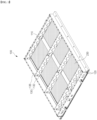
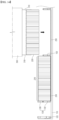
- FIG. 1 is a perspective view of the pack case 100 according to one embodiment of the present invention
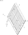
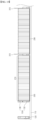
- FIG. 2 is a perspective view showing the upper cross beam 136 detached from the pack case 100 of FIG. 1 .
- FIGS. 1 and 2 the overall configuration of the pack case 100 according to an embodiment of the present invention will be described.
- the present invention relates to a pack case (100) that accommodates a plurality of cell laminates (210) equally divided.
- a cell laminate 210 is a single completed battery cell that is capable of being charged and discharged as a secondary battery, and is used herein in an encompassing sense regardless of whether it is a pouch battery, prismatic battery, or the like.
- a plurality of cell laminates 210 may comprise a battery module housed in a single housing and mounted in the pack case 100
- the plurality of cell laminates 210 are illustrated in the drawings as a simple aggregation of pouch-type batteries, particularly considering that the pack case 100 of the present invention is suitable for a cell-to-pack structure that does not utilize various module components such as module housings, etc.
- the illustrated pack case 100 includes a base plate 110 and side plates 120 coupled along a periphery of the base plate 110 to form a receiving space therein.
- the base plate 110 comprises a cross beam 130 coupled to the base plate 110 in a transverse direction, with reference to the drawings, as a separation wall member to divide the receiving space within the base plate 110.
- the cross beam 130 of the pack case 100 has a length corresponding to the transverse width of the base plate 110, such that both ends of the cross beam 130 are in contact with or adjacent to the side plates 120.
- the cross beam 130 comprises two cross beams: a lower cross beam 132 that couples directly to the base plate 110 to transversely divide the receiving space inside the base plate 110, and an upper cross beam 136 that couples to the lower cross beam 132.
- the upper cross beam 136 is bi-layer in that the lower cross beam 132 and the upper cross beam 136 are upwardly coupled with respect to the lower cross beam 132, i.e., they are aligned and coupled such that the upper cross beam 136 is overlapping the top of the lower cross beam 132, thereby forming a single cross beam 130.
- the pack case 100 of the present invention has many advantages. For example, since only the lower cross beam 132 needs to be joined to the base plate 110, the reduced height of the cross beam 130 facilitates welding operations on the lower cross beam 132 by improving accessibility of the welding tool tip. Further, the plurality of cell laminates 210 can be mounted in the pack case 100 before the upper cross beam 136 is assembled, which reduces the problem of interference with the cross beam 130, thereby improving the workability of the loading jig 300 for handling the plurality of cell laminates 210 at once.
- the cross beam 130 by constructing the cross beam 130 as a bi-layer structure, it is possible to contribute to the lightweight of the battery pack 200 by constructing the upper cross beam 136, which does not involve welding to the base plate 110, from a lightweight different material, for example, a metal material such as stainless steel that can be welded to the lower cross beam 132 while the upper cross beam 136 is constructed from a lighter weight engineering plastic or the like.
- a lightweight different material for example, a metal material such as stainless steel that can be welded to the lower cross beam 132 while the upper cross beam 136 is constructed from a lighter weight engineering plastic or the like.
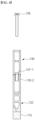
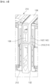
- FIG. 3 is a drawing illustrating one embodiment of the coupling structure of the lower and upper cross beams 132, 136
- FIG. 4 is a cross-sectional view cut along the line "A-A" in FIG. 3
- the lower cross beam 132 has a first uneven structure 133 with repeated concave portions 133-1 and projecting portions 133-2 in the upward engagement direction of the upper cross beam 136
- the upper cross beam 136 correspondingly has a second uneven structure 137 in a form complementary to the first uneven structure 133.
- first uneven structure 133 and the second uneven structure 137 have a complementary shape
- concave portion 133-1 of the first uneven structure 133 and the projecting portion 137-2 of the second uneven structure 137, and the projecting portion 133-2 of the first uneven structure 133 and the concave portion 137-1 of the second uneven structure 137 form a kind of overlapping structure facing each other.
- the complementary uneven structures 133, 137 By the complementary uneven structures 133, 137, a single coupling position of the upper cross beam 136 with respect to the lower cross beam 132 is determined, thereby ensuring accurate alignment of the lower and upper cross beams 132, 136, and thereby facilitating the operation of completing the fastening with the bolts 138 in the prefabricated state of the lower and upper cross beams 132, 136.
- the first uneven structure 133 of the lower cross beam 132 is also advantageously utilized to avoid interference with the loading jig 300.
- the lower cross beam 132 may be coupled to the base plate 110 by welding, and the upper cross beam 136 may be coupled to the lower cross beam 132 by bolts 138, and by such a separate bilayer coupling structure, it is possible to make the upper cross beam 136 of a lightweight different material.
- the lower and upper cross beams 132, 136 are essentially hollow and have a ribbed structure connecting the two side walls for rigidity reinforcement.
- the hollow structure of the lower and upper cross beams 132, 136 allows for lightweighting, and is also advantageous for retarding heat transfer due to thermal runaway by inhibiting heat generated by any of the cell laminates 210 within the pack case 100 from moving, in the form of conduction, to the other cell laminates 210 spaced between the cross beams 130.
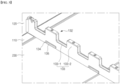
- FIG. 5 is a perspective view illustrating the welding structure of the lower cross beam 132 to the base plate 110
- FIG. 6 is a plan view illustrating the welding points of the lower cross beam 132 to the base plate 110.
- the cross beam 130 is an important member of the pack case 100 that strengthens the transverse rigidity of the pack case 100 and is welded or bolted to the base plate 110. Welding is often used due to its strength, productivity, and light weight, but in this case, the welding bead 135 that forms on the welding surface of the cross beam 130 and the base plate 110 causes problems with the safety and capacity of the battery pack 200.
- a plurality of cell laminates 210 are mounted inside the cross beam 130, especially in a module housing-free or simplified cell-to-pack structure, the cell laminates 210 interfere with the welding bead 135, and in an environment subject to long-term vibration or shock, the cell laminates 210 that interfere with the welding bead 135 are susceptible to damage or breakage, which can cause serious safety issues such as fire.
- a design that avoids interference with the welding bead 135 creates dead space, which reduces the energy density of the battery pack 200.
- the welding structure of the lower cross beam 132 of FIGS. 5 and 6 may solve this problem of welding beads 135.
- the lower cross beam 132 has at least one concave welding groove 134 at a boundary with the base plate 110.
- the lower cross beam 132 is welded against the base plate 110 via the welding grooves 134, thereby forming a welding bead 135 in the concave space within the welding grooves 134, wherein the welding bead 135 formed within the welding grooves 134 does not protrude outside of the lower cross beam 132.
- interference of the cell laminate 210 by the welding bead 135 and/or generation of dead space by the avoidance design can be prevented.
- the size of the welding groove 134 may be designed in consideration of the size of the welding tool tip and the size of the welding bead 135 depending on the welding method.
- wire laser welding has a small tip size and the size of the welding bead 135 is on the order of 2 to 3 millimeters, so the size of the welding groove 134 can be correspondingly made to be on the order of a few millimeters in height and depth.
- the welding grooves 134 may be provided on both sides of the lower cross beam 132.
- each of the welding grooves 134 provided on both sides of the lower cross beam 132 may be at least partially non-overlapping along the direction in which they face each other, i.e., dispersed and disposed crossed apart from each other.
- FIGS. 7 and 8 illustrate a pack case 100 according to a third embodiment of the present invention.
- the third embodiment of FIGS. 7 and 8 is characterized in that the lower cross beam 132 and the upper cross beam 136 are each provided with fastening grooves 140 that regulate the installation position of the cell laminates 210.
- the fastening grooves 140 in the cross beam 130 can be utilized to rigidly regulate the installation position of the cell laminates.
- the plurality of cell laminates 210 with regulated positions are installed in precise locations and are less likely to shift in position during use of the battery pack 200, thereby improving the stability of the battery pack 200.
- FIG. 7 shows an embodiment of the fastening groove 140, wherein the fastening groove 140 is formed in the form of an open groove 142 with an opening in the coupling surface of the lower cross beam 132 and the upper cross beam 136.
- the fastening groove 140 in FIG. 7 is formed in the form of a half-and-half longitudinal groove in the lower cross beam 132 and the upper cross beam 136, with one side of each longitudinal groove, i.e., the coupling surface of the lower and upper cross beams 132, 136, forming an open opening.
- FIG. 8 shows another embodiment of the fastening grooves 140, wherein the fastening grooves 140 are formed in the form of holes 144 separated from each other by the coupling surfaces of the lower cross beam 132 and the upper cross beam 136.
- the pair of fastening grooves 140 do not connect as one, even when the lower and upper cross beams 132, 136 are coupled.
- the shape of the hole 144 is illustrated in FIG. 8 as a semicircular hole, but is not limited thereto, and various other shapes not shown, such as a circular hole or a square hole, etc. are possible.
- the fastening groove 140 of the separated structure of FIG. 8 may include an induction groove 145 extending from the coupling surface of the lower cross beam 132 and the upper cross beam 136 to a hole 144.
- the induction groove 145 is intended to facilitate gliding of the protruding structure 214 that is engaged in the fastening groove 140, as will be described further below.
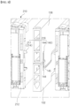
- FIGS. 9 and 10 are drawings to illustrate a configuration in which the installation position of the plurality of cell laminates 210 is regulated by the fastening grooves 140 of FIG. 7 .
- FIG. 9 illustrates a configuration in which the plurality of cell laminates 210 are mounted on the pack case 100 in a third embodiment.
- the cell laminate 210 shown includes a busbar frame assembly 212 that couples to the cell laminate 210 at two ends (transverse ends in the drawing) from which leads protrude, and the busbar frame assembly 212 has a protruding structure 214 that engages in respective fastening grooves 140 of the lower cross beam 132 and the upper cross beam 136.
- the protruding structures 214 As the protruding structures 214 corresponding to the fastening grooves 140 in FIG. 7 , the protruding structures 214 provided in the busbar frame assembly 212 form a fin structure 215 corresponding to a shape in which the open grooves 142 of the lower and upper cross beams 132, 136 are connected
- FIG. 10 illustrates a busbar frame assembly 212 coupled to a plurality of cell laminates 210 with respect to the fastening grooves 140 of FIG. 7 .
- the plurality of cell laminates 210 are not shown in FIG. 10 , and adjacent cell laminates 210 on either side that share a single cross beam 130 are regulated in position by the same fastening groove 140.
- the cross beam 130 is installed in the pack case 100 with only the lower cross beam 132 installed, and the openings of the open groove 142, which are the fastening grooves 140 of the lower cross beam 132, are open upward. Accordingly, when the plurality of cell laminate 210 is inserted between the lower cross beams 132 from top to bottom, approximately half of the fin structures 215 of the busbar frame assembly 212 fit into the open grooves 142, and fastening between these fin structures 215 and the open grooves 142 occurs at both ends of the plurality of cell laminate 210, thereby aligning the installation position of the plurality of cell laminate 210.
- the pack case 100 of the third embodiment can precisely regulate the mounting position of all cell laminates 210 by the fastening grooves 140 of the cross beams 130 and the protruding structures 214 of the cell laminates 210.
- FIG. 11 illustrates the coupling of the busbar frame assembly 212 to the fastening groove 140 of FIG. 8 .
- the embodiment of FIG. 8 is the same in that the position of the plurality of cell laminates 210 is regulated by the coupling of the lower and upper cross beams 132, 136, with the difference being the fastening of the protruding structure 214 to the fastening groove 140.
- the fastening grooves 140 are formed in the form of holes 144 separated from each other by the coupling surfaces of the lower cross beam 132 and the upper cross beam 136, and correspondingly, the protruding structures 214 of the busbar frame assembly 212 comprise snap-fit joints 216 comprising cantilever lugs 217 that engage the holes 144 of the lower and upper cross beams 132, 136.
- the fastening groove 140 is configured in the form of a separate hole 144 without an incision
- the cantilever lugs 217 of the protruding structure 214 comprising the snap-fit joint 216 can be resiliently bent to allow the projecting portion of the cantilever ends to enter the hole 144 and be fastened.
- the fastening groove 140 may comprise an induction groove 145 extending from the coupling surface of the lower and upper cross beams 132, 136, respectively, to the hole 144, whereby the cantilever lugs 217 of the snap-fit joint 216 may glide over the surface of the induction groove 145 and gently fasten into the hole 144.
- the protruding structures 214 of the plurality of cell laminates 210 may be preferably disposed on either side of the busbar frame assembly 212 facing the respective fastening grooves 140 of the lower and upper cross beams 132, 136.
- the busbar frame assembly 212 may include an insulating cover 218 coupled to a front surface thereof. The insulating cover 218 is a covering member for electrically and physically protecting the front side of the busbar frame assembly 212 that faces the side plate 120, or other cell laminate 210.
- the insulating cover 218 may also be configured to be easily attached to the busbar frame assembly 212 by a snap-fit structure, and the insulating cover 218 is designed to not block or obscure the protruding structures 214 disposed on the sides of the busbar frame assembly 212 (refer to FIG. 9 ).
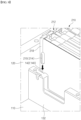
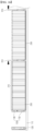
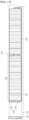
- FIG. 12 is a perspective view of a battery pack 200 according to an embodiment of the present invention.
- the battery pack 200 is completed by mounting a plurality of cell laminates 210 each in a plurality of receiving spaces divided by cross beams 130.
- the embodiment shown is a battery pack 200 of cell-to-pack construction with a plurality of cell laminates 210 assembled between a busbar frame assembly 212 for electrical connections without a separate module housing, and leads closing the top surface are omitted to show the internal structure.
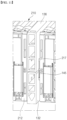
- FIG. 13 is a cross-sectional view cut along the "B-B" line of FIG. 12 , showing an insulating sheet or compression pad 220 interposed between the lower and upper cross beams 132, 136 and the contact surfaces of the cell laminate 210.
- the insulating sheet and the compression pad are referred to for convenience as the insulating sheet for a thin member and the compression pad for a thicker member with a relatively high elasticity, and both are protective members for reinforcing electrical insulation and layer rigidity and abrasion resistance of the cell laminate 210, and serve to protect the cell laminate 210 against the cross beam 130.
- FIGS. 14 to 17 illustrate a series of steps for manufacturing a battery pack 200 using the pack case 100 of the present invention described above in first to third embodiments.
- the method of manufacturing the battery pack 200 begins with the first step of preparing the pack case 100 of the present invention, namely, a pack case 100 comprising a base plate 110, side plates 120 coupled along the perimeter of the base plate 110 to form a receiving space therein, and a lower cross beam 132 coupled to the base plate 110 to divide the receiving space inside the base plate 110.
- a first step only the lower cross beam 132 of the entire cross beam 130 is prepared in the pack case 100, and in this state, the loading of the cell laminate 210 takes place.
- the plurality of cell laminates 210 are loaded into the receiving space divided by the lower cross beam 132, and in particular, for productivity, a loading jig 300 can be used to handle a plurality of cell laminates 210 at once.
- FIG. 14 is a perspective view illustrating an embodiment in which the gripper 310 of the loading jig 300 gripping the plurality of cell laminates 210 enters the lower cross beam 132
- FIG. 15 is a cross-sectional view illustrating the loading jig 300 of FIG. 14 with the gripper 310 entering the lower cross beam 132.
- the pack case 100 prepared in the first step comprises a first uneven structure 133 in which the lower cross beam 132 has repeated concave portions 133-1 and projecting portions 133-2 in the direction of coupling of the lower cross beam 132 and the upper cross beam 136.
- the loading jig 300 has grippers 310 for gripping the plurality of cell laminates 210 integrally.
- the grippers 310 of the loading jig 300 are provided in pairs that grip two sides of the cell laminate 210 parallel to the lower cross beam 132, and may additionally have grippers 310 that grip other sides of the cell laminate 210.
- the grippers 310 gripping both sides of the cell laminate 210 facing the lower cross beam 132 may include a plurality of feet corresponding to a location (or locations and number) of concave portions 133-1 of the first uneven structure 133 formed in the lower cross beam 132. Accordingly, the gripper 310 of the loading jig 300 enters the concave portion 133-1 of the first uneven structure 133 and grips the plurality of cell laminates 210 on the base plate 110.
- the depth of the concave portion 133-1 of the first uneven structure 133 is at least half of the total height of the cell laminate 210.
- the gripper 310 of the loading jig 300 can have a gripping area of at least half of the total height of the cell laminate 210.
- the gripper 310 of the loading jig 300 can firmly grip and enter the cell laminate 210 without causing interference with the lower cross beam 132, and can also stably and shock-free place the cell laminate 210 on the base plate 110.
- the cross beam 130 of the pack case 100 comprises the fastening grooves 140 described in the third embodiment
- the plurality of cell laminates 210 comprises a protruding structure 214 that fastens to the fastening grooves 140, so that the installation position of the plurality of cell laminates 210 in the pack case 100 is precisely controlled by the loading jig.
- a thermal resin 230 which serves to improve the heat transfer performance of the battery pack 200 by facilitating conduction heat transfer between the base plate 110 and the cell laminate 210.
- the thermal resin 230 directly mediates the conduction heat transfer between the base plate 110 and the cell laminate 210 without the need for an intermediate structure such as a module housing, allowing for better heat dissipation.
- the thermal resin 230 is evenly applied to a suitable thickness on the base plate 110 prior to mounting the cell laminate 210 inside the pack case 100.
- FIG. 16 is a cross-sectional view illustrating the leaving process of the loading jig 300 after the plurality of cell laminates 210 have been seated. Due to the thinner thickness of the grippers 310 compared to the thickness of the lower cross beam 132, once the grippers 310 of the loading jig 300 have gripped the plurality of cell laminates 210 integrally and seated them on the base plate 110, the grippers 310 can retract, release their grip, and continue to leave upwardly on the lower cross beam 132.
- the third step of coupling the upper cross beam 136 with respect to the lower cross beam 132 on which the plurality of cell laminates 210 are mounted is then performed, as shown in FIG. 17 .
- the upper cross beam 136 with respect to the lower cross beam 132 By engaging the upper cross beam 136 with respect to the lower cross beam 132, sufficient surface pressure can be formed over the entire height of the cell laminate 210.
- the surface pressure applied to the cell laminate 210 By the surface pressure applied to the cell laminate 210, the swelling phenomenon that occurs as the cell laminate 210 repeats charging and discharging can be effectively suppressed.
- the gripping surfaces of the plurality of cell laminates 210 gripped by the loading jig 300 may be attached with insulating sheets or compression pads 220 as described above, which may also assist in suppressing the swelling phenomenon.
Landscapes
- Chemical & Material Sciences (AREA)
- Chemical Kinetics & Catalysis (AREA)
- Electrochemistry (AREA)
- General Chemical & Material Sciences (AREA)
- Engineering & Computer Science (AREA)
- Manufacturing & Machinery (AREA)
- Battery Mounting, Suspending (AREA)
- Secondary Cells (AREA)
Applications Claiming Priority (3)
| Application Number | Priority Date | Filing Date | Title |
|---|---|---|---|
| KR20220167142 | 2022-12-02 | ||
| KR1020230035421A KR20240082976A (ko) | 2022-12-02 | 2023-03-17 | 배터리 팩 |
| PCT/KR2023/019152 WO2024117695A1 (ko) | 2022-12-02 | 2023-11-24 | 배터리 팩 |
Publications (2)
| Publication Number | Publication Date |
|---|---|
| EP4459766A1 true EP4459766A1 (de) | 2024-11-06 |
| EP4459766A4 EP4459766A4 (de) | 2025-07-16 |
Family
ID=91324529
Family Applications (1)
| Application Number | Title | Priority Date | Filing Date |
|---|---|---|---|
| EP23898226.8A Pending EP4459766A4 (de) | 2022-12-02 | 2023-11-24 | Batteriepack |
Country Status (4)
| Country | Link |
|---|---|
| US (1) | US20250141023A1 (de) |
| EP (1) | EP4459766A4 (de) |
| JP (1) | JP2025505008A (de) |
| WO (1) | WO2024117695A1 (de) |
Families Citing this family (1)
| Publication number | Priority date | Publication date | Assignee | Title |
|---|---|---|---|---|
| US11756934B2 (en) * | 2021-04-16 | 2023-09-12 | Taiwan Semiconductor Manufacturing Company, Ltd. | Semiconductor structure and manufacturing method thereof |
Family Cites Families (12)
| Publication number | Priority date | Publication date | Assignee | Title |
|---|---|---|---|---|
| DE102012015818B4 (de) * | 2012-08-10 | 2023-10-26 | Dr. Ing. H.C. F. Porsche Ag | Kraftfahrzeugbatterie |
| US10170739B2 (en) * | 2015-10-27 | 2019-01-01 | Bosch Battery Systems GmbH | Pin mount for battery module |
| JP2018206495A (ja) * | 2017-05-31 | 2018-12-27 | 株式会社日立製作所 | 二次電池モジュール |
| TWI790120B (zh) | 2017-06-02 | 2023-01-11 | 美商輝瑞大藥廠 | 對flt3具特異性之抗體及其用途 |
| KR102378527B1 (ko) * | 2018-12-05 | 2022-03-23 | 주식회사 엘지에너지솔루션 | 전지 모듈 및 그 제조 방법 |
| JP7194094B2 (ja) * | 2019-09-10 | 2022-12-21 | 株式会社神戸製鋼所 | 電動車両用バッテリーケース |
| CN211017198U (zh) * | 2019-12-31 | 2020-07-14 | 宁德时代新能源科技股份有限公司 | 电池模块、电池组及装置 |
| KR102802106B1 (ko) * | 2020-07-28 | 2025-05-02 | 에스케이온 주식회사 | 배터리 팩 |
| CN214898744U (zh) * | 2021-03-09 | 2021-11-26 | 恒大新能源技术(深圳)有限公司 | 一种电池包 |
| KR20220167142A (ko) | 2021-06-11 | 2022-12-20 | 주식회사 케이티앤지 | 가연성 열원을 포함하는 에어로졸 생성 물품 |
| CN215299382U (zh) * | 2021-07-28 | 2021-12-24 | 蜂巢能源科技有限公司 | 电池托盘、电池包及动力装置 |
| CN215731965U (zh) * | 2021-08-19 | 2022-02-01 | 东软睿驰汽车技术(沈阳)有限公司 | 电池包箱体 |
-
2023
- 2023-11-24 US US18/836,933 patent/US20250141023A1/en active Pending
- 2023-11-24 WO PCT/KR2023/019152 patent/WO2024117695A1/ko not_active Ceased
- 2023-11-24 EP EP23898226.8A patent/EP4459766A4/de active Pending
- 2023-11-24 JP JP2024546181A patent/JP2025505008A/ja active Pending
Also Published As
| Publication number | Publication date |
|---|---|
| JP2025505008A (ja) | 2025-02-19 |
| WO2024117695A1 (ko) | 2024-06-06 |
| US20250141023A1 (en) | 2025-05-01 |
| EP4459766A4 (de) | 2025-07-16 |
Similar Documents
| Publication | Publication Date | Title |
|---|---|---|
| US20230352722A1 (en) | Linked battery module and linked battery pack | |
| KR101794265B1 (ko) | 보강 비드부를 포함하는 배터리 팩 | |
| EP3852187B1 (de) | Batteriepack und fahrzeug | |
| EP2450990B1 (de) | Batteriemodul mit Batteriezellenhalter | |
| EP3926734B1 (de) | Batteriemodul und batteriepack damit | |
| EP4167361A1 (de) | Batteriepack | |
| JP7368609B2 (ja) | 補強ビームを用いた冷却プレートの締結を改善した電池モジュールおよびそれを含む電池パック | |
| EP4459766A1 (de) | Batteriepack | |
| EP4345985B1 (de) | Batteriemodul | |
| JP2019197622A (ja) | 電池パック | |
| US20250158186A1 (en) | Battery Pack | |
| KR20230098059A (ko) | 개선된 안전성과 조립성을 갖는 배터리 모듈 | |
| JP7693101B2 (ja) | バッテリーパック及びこれを含む自動車 | |
| KR20240019677A (ko) | 배터리 팩 | |
| EP4468480A2 (de) | Batteriemodul und batteriepack | |
| US20140363733A1 (en) | Sealed battery | |
| JP7753514B2 (ja) | バッテリーパック | |
| KR20240082976A (ko) | 배터리 팩 | |
| CN118661324A (zh) | 电池组 | |
| CN117859236A (zh) | 电池组 | |
| JP7751746B2 (ja) | 熱伝播防止構造が改善されたパックケース | |
| KR20250091059A (ko) | 축전 스택 | |
| JP2025518953A (ja) | 電池モジュールおよびこれを含む電池パック | |
| KR20250000193A (ko) | 배터리팩 | |
| KR20250158416A (ko) | 배터리 팩 |
Legal Events
| Date | Code | Title | Description |
|---|---|---|---|
| STAA | Information on the status of an ep patent application or granted ep patent |
Free format text: STATUS: THE INTERNATIONAL PUBLICATION HAS BEEN MADE |
|
| PUAI | Public reference made under article 153(3) epc to a published international application that has entered the european phase |
Free format text: ORIGINAL CODE: 0009012 |
|
| STAA | Information on the status of an ep patent application or granted ep patent |
Free format text: STATUS: REQUEST FOR EXAMINATION WAS MADE |
|
| 17P | Request for examination filed |
Effective date: 20240731 |
|
| AK | Designated contracting states |
Kind code of ref document: A1 Designated state(s): AL AT BE BG CH CY CZ DE DK EE ES FI FR GB GR HR HU IE IS IT LI LT LU LV MC ME MK MT NL NO PL PT RO RS SE SI SK SM TR |
|
| A4 | Supplementary search report drawn up and despatched |
Effective date: 20250617 |
|
| RIC1 | Information provided on ipc code assigned before grant |
Ipc: H01M 50/264 20210101AFI20250611BHEP Ipc: H01M 50/291 20210101ALI20250611BHEP Ipc: H01M 50/502 20210101ALI20250611BHEP Ipc: H01M 50/204 20210101ALI20250611BHEP Ipc: H01M 50/289 20210101ALI20250611BHEP Ipc: H01M 50/209 20210101ALI20250611BHEP Ipc: H01M 50/211 20210101ALI20250611BHEP Ipc: H01M 50/262 20210101ALI20250611BHEP Ipc: H01M 50/271 20210101ALI20250611BHEP Ipc: H01M 50/507 20210101ALI20250611BHEP |