EP4459762A1 - Electricity storage pack - Google Patents
Electricity storage pack Download PDFInfo
- Publication number
- EP4459762A1 EP4459762A1 EP22915755.7A EP22915755A EP4459762A1 EP 4459762 A1 EP4459762 A1 EP 4459762A1 EP 22915755 A EP22915755 A EP 22915755A EP 4459762 A1 EP4459762 A1 EP 4459762A1
- Authority
- EP
- European Patent Office
- Prior art keywords
- electricity storage
- pack according
- housing
- storage pack
- lid
- Prior art date
- Legal status (The legal status is an assumption and is not a legal conclusion. Google has not performed a legal analysis and makes no representation as to the accuracy of the status listed.)
- Pending
Links
Images






Classifications
-
- H—ELECTRICITY
- H01—ELECTRIC ELEMENTS
- H01M—PROCESSES OR MEANS, e.g. BATTERIES, FOR THE DIRECT CONVERSION OF CHEMICAL ENERGY INTO ELECTRICAL ENERGY
- H01M50/00—Constructional details or processes of manufacture of the non-active parts of electrochemical cells other than fuel cells, e.g. hybrid cells
- H01M50/20—Mountings; Secondary casings or frames; Racks, modules or packs; Suspension devices; Shock absorbers; Transport or carrying devices; Holders
- H01M50/204—Racks, modules or packs for multiple batteries or multiple cells
- H01M50/207—Racks, modules or packs for multiple batteries or multiple cells characterised by their shape
- H01M50/213—Racks, modules or packs for multiple batteries or multiple cells characterised by their shape adapted for cells having curved cross-section, e.g. round or elliptic
-
- H—ELECTRICITY
- H01—ELECTRIC ELEMENTS
- H01G—CAPACITORS; CAPACITORS, RECTIFIERS, DETECTORS, SWITCHING DEVICES, LIGHT-SENSITIVE OR TEMPERATURE-SENSITIVE DEVICES OF THE ELECTROLYTIC TYPE
- H01G11/00—Hybrid capacitors, i.e. capacitors having different positive and negative electrodes; Electric double-layer [EDL] capacitors; Processes for the manufacture thereof or of parts thereof
- H01G11/10—Multiple hybrid or EDL capacitors, e.g. arrays or modules
-
- H—ELECTRICITY
- H01—ELECTRIC ELEMENTS
- H01G—CAPACITORS; CAPACITORS, RECTIFIERS, DETECTORS, SWITCHING DEVICES, LIGHT-SENSITIVE OR TEMPERATURE-SENSITIVE DEVICES OF THE ELECTROLYTIC TYPE
- H01G11/00—Hybrid capacitors, i.e. capacitors having different positive and negative electrodes; Electric double-layer [EDL] capacitors; Processes for the manufacture thereof or of parts thereof
- H01G11/14—Arrangements or processes for adjusting or protecting hybrid or EDL capacitors
- H01G11/18—Arrangements or processes for adjusting or protecting hybrid or EDL capacitors against thermal overloads, e.g. heating, cooling or ventilating
-
- H—ELECTRICITY
- H01—ELECTRIC ELEMENTS
- H01G—CAPACITORS; CAPACITORS, RECTIFIERS, DETECTORS, SWITCHING DEVICES, LIGHT-SENSITIVE OR TEMPERATURE-SENSITIVE DEVICES OF THE ELECTROLYTIC TYPE
- H01G11/00—Hybrid capacitors, i.e. capacitors having different positive and negative electrodes; Electric double-layer [EDL] capacitors; Processes for the manufacture thereof or of parts thereof
- H01G11/78—Cases; Housings; Encapsulations; Mountings
- H01G11/82—Fixing or assembling a capacitive element in a housing, e.g. mounting electrodes, current collectors or terminals in containers or encapsulations
-
- H—ELECTRICITY
- H01—ELECTRIC ELEMENTS
- H01M—PROCESSES OR MEANS, e.g. BATTERIES, FOR THE DIRECT CONVERSION OF CHEMICAL ENERGY INTO ELECTRICAL ENERGY
- H01M50/00—Constructional details or processes of manufacture of the non-active parts of electrochemical cells other than fuel cells, e.g. hybrid cells
- H01M50/10—Primary casings; Jackets or wrappings
- H01M50/102—Primary casings; Jackets or wrappings characterised by their shape or physical structure
- H01M50/112—Monobloc comprising multiple compartments
-
- H—ELECTRICITY
- H01—ELECTRIC ELEMENTS
- H01M—PROCESSES OR MEANS, e.g. BATTERIES, FOR THE DIRECT CONVERSION OF CHEMICAL ENERGY INTO ELECTRICAL ENERGY
- H01M50/00—Constructional details or processes of manufacture of the non-active parts of electrochemical cells other than fuel cells, e.g. hybrid cells
- H01M50/20—Mountings; Secondary casings or frames; Racks, modules or packs; Suspension devices; Shock absorbers; Transport or carrying devices; Holders
- H01M50/262—Mountings; Secondary casings or frames; Racks, modules or packs; Suspension devices; Shock absorbers; Transport or carrying devices; Holders with fastening means, e.g. locks
-
- H—ELECTRICITY
- H01—ELECTRIC ELEMENTS
- H01M—PROCESSES OR MEANS, e.g. BATTERIES, FOR THE DIRECT CONVERSION OF CHEMICAL ENERGY INTO ELECTRICAL ENERGY
- H01M50/00—Constructional details or processes of manufacture of the non-active parts of electrochemical cells other than fuel cells, e.g. hybrid cells
- H01M50/20—Mountings; Secondary casings or frames; Racks, modules or packs; Suspension devices; Shock absorbers; Transport or carrying devices; Holders
- H01M50/262—Mountings; Secondary casings or frames; Racks, modules or packs; Suspension devices; Shock absorbers; Transport or carrying devices; Holders with fastening means, e.g. locks
- H01M50/264—Mountings; Secondary casings or frames; Racks, modules or packs; Suspension devices; Shock absorbers; Transport or carrying devices; Holders with fastening means, e.g. locks for cells or batteries, e.g. straps, tie rods or peripheral frames
-
- H—ELECTRICITY
- H01—ELECTRIC ELEMENTS
- H01M—PROCESSES OR MEANS, e.g. BATTERIES, FOR THE DIRECT CONVERSION OF CHEMICAL ENERGY INTO ELECTRICAL ENERGY
- H01M50/00—Constructional details or processes of manufacture of the non-active parts of electrochemical cells other than fuel cells, e.g. hybrid cells
- H01M50/20—Mountings; Secondary casings or frames; Racks, modules or packs; Suspension devices; Shock absorbers; Transport or carrying devices; Holders
- H01M50/271—Lids or covers for the racks or secondary casings
-
- H—ELECTRICITY
- H01—ELECTRIC ELEMENTS
- H01M—PROCESSES OR MEANS, e.g. BATTERIES, FOR THE DIRECT CONVERSION OF CHEMICAL ENERGY INTO ELECTRICAL ENERGY
- H01M50/00—Constructional details or processes of manufacture of the non-active parts of electrochemical cells other than fuel cells, e.g. hybrid cells
- H01M50/20—Mountings; Secondary casings or frames; Racks, modules or packs; Suspension devices; Shock absorbers; Transport or carrying devices; Holders
- H01M50/289—Mountings; Secondary casings or frames; Racks, modules or packs; Suspension devices; Shock absorbers; Transport or carrying devices; Holders characterised by spacing elements or positioning means within frames, racks or packs
-
- H—ELECTRICITY
- H01—ELECTRIC ELEMENTS
- H01M—PROCESSES OR MEANS, e.g. BATTERIES, FOR THE DIRECT CONVERSION OF CHEMICAL ENERGY INTO ELECTRICAL ENERGY
- H01M50/00—Constructional details or processes of manufacture of the non-active parts of electrochemical cells other than fuel cells, e.g. hybrid cells
- H01M50/20—Mountings; Secondary casings or frames; Racks, modules or packs; Suspension devices; Shock absorbers; Transport or carrying devices; Holders
- H01M50/289—Mountings; Secondary casings or frames; Racks, modules or packs; Suspension devices; Shock absorbers; Transport or carrying devices; Holders characterised by spacing elements or positioning means within frames, racks or packs
- H01M50/293—Mountings; Secondary casings or frames; Racks, modules or packs; Suspension devices; Shock absorbers; Transport or carrying devices; Holders characterised by spacing elements or positioning means within frames, racks or packs characterised by the material
-
- H—ELECTRICITY
- H01—ELECTRIC ELEMENTS
- H01M—PROCESSES OR MEANS, e.g. BATTERIES, FOR THE DIRECT CONVERSION OF CHEMICAL ENERGY INTO ELECTRICAL ENERGY
- H01M50/00—Constructional details or processes of manufacture of the non-active parts of electrochemical cells other than fuel cells, e.g. hybrid cells
- H01M50/30—Arrangements for facilitating escape of gases
-
- H—ELECTRICITY
- H01—ELECTRIC ELEMENTS
- H01M—PROCESSES OR MEANS, e.g. BATTERIES, FOR THE DIRECT CONVERSION OF CHEMICAL ENERGY INTO ELECTRICAL ENERGY
- H01M50/00—Constructional details or processes of manufacture of the non-active parts of electrochemical cells other than fuel cells, e.g. hybrid cells
- H01M50/30—Arrangements for facilitating escape of gases
- H01M50/317—Re-sealable arrangements
- H01M50/325—Re-sealable arrangements comprising deformable valve members, e.g. elastic or flexible valve members
-
- H—ELECTRICITY
- H01—ELECTRIC ELEMENTS
- H01M—PROCESSES OR MEANS, e.g. BATTERIES, FOR THE DIRECT CONVERSION OF CHEMICAL ENERGY INTO ELECTRICAL ENERGY
- H01M50/00—Constructional details or processes of manufacture of the non-active parts of electrochemical cells other than fuel cells, e.g. hybrid cells
- H01M50/40—Separators; Membranes; Diaphragms; Spacing elements inside cells
- H01M50/471—Spacing elements inside cells other than separators, membranes or diaphragms; Manufacturing processes thereof
- H01M50/477—Spacing elements inside cells other than separators, membranes or diaphragms; Manufacturing processes thereof characterised by their shape
-
- H—ELECTRICITY
- H01—ELECTRIC ELEMENTS
- H01G—CAPACITORS; CAPACITORS, RECTIFIERS, DETECTORS, SWITCHING DEVICES, LIGHT-SENSITIVE OR TEMPERATURE-SENSITIVE DEVICES OF THE ELECTROLYTIC TYPE
- H01G11/00—Hybrid capacitors, i.e. capacitors having different positive and negative electrodes; Electric double-layer [EDL] capacitors; Processes for the manufacture thereof or of parts thereof
- H01G11/78—Cases; Housings; Encapsulations; Mountings
-
- Y—GENERAL TAGGING OF NEW TECHNOLOGICAL DEVELOPMENTS; GENERAL TAGGING OF CROSS-SECTIONAL TECHNOLOGIES SPANNING OVER SEVERAL SECTIONS OF THE IPC; TECHNICAL SUBJECTS COVERED BY FORMER USPC CROSS-REFERENCE ART COLLECTIONS [XRACs] AND DIGESTS
- Y02—TECHNOLOGIES OR APPLICATIONS FOR MITIGATION OR ADAPTATION AGAINST CLIMATE CHANGE
- Y02E—REDUCTION OF GREENHOUSE GAS [GHG] EMISSIONS, RELATED TO ENERGY GENERATION, TRANSMISSION OR DISTRIBUTION
- Y02E60/00—Enabling technologies; Technologies with a potential or indirect contribution to GHG emissions mitigation
- Y02E60/10—Energy storage using batteries
Definitions
- the present disclosure relates to an electricity storage pack.
- An electricity storage pack includes a plurality of electricity storage blocks.
- Each electricity storage block includes a plurality of cells (elementary batteries) held in a cell holder (for example, Patent Literature (PTL) 1).
- PTL Patent Literature 1
- respective electricity storage blocks that are linearly connected are fixed to one another by screws that penetrate the cell holders.
- the electricity storage pack includes a housing that houses a plurality of electricity storage blocks.
- the housing needs to be firmly fixed to the electricity storage blocks, no specific configuration is disclosed.
- design changes such as making the cell holders stronger than necessary, are required to increase the fixing strength between the housing and the electricity storage blocks.
- An object of the present disclosure is to provide an electricity storage pack that is capable of firmly fixing a housing and electricity storage blocks to one another.
- An electricity storage module is an electricity storage pack that includes at least one electricity storage block including a plurality of cells, and a housing that houses the at least one electricity storage block.
- the at least one electricity storage block and the housing are fixed by a fixing shaft that extends in a first direction and penetrates one side face of the housing and the at least one electricity storage block.
- the housing and the electricity storage blocks are firmly fixed to one another.
- electricity storage pack 10 With reference to FIG. 1 to FIG. 4 , electricity storage pack 10 according to an example of an embodiment will be described.
- Electricity storage pack 10 is mainly mounted in an electrically powered vehicle to supply electric power to a drive motor.
- Electricity storage pack 10 according to the present disclosure is used, for example, as a power source for electric bikes, assisted bicycles, electric wheelchairs, electric tricycles, electric carts, and the like.
- the present disclosure does not specify the usage of electricity storage pack 10, which can also be used as a power source for various electrical equipment used outdoors, such as power tools.
- Electricity storage pack 10 is capable of firmly fixing housing 50 and at least one electricity storage block 20 to one other, as will be described in detail below.
- electricity storage pack 10 according to the present disclosure is capable of reducing the number of components.
- electricity storage pack 10 includes a plurality of electricity storage blocks 20 each including a plurality of cells 30, circuit board 40 in which a protection circuit that controls charging and discharging of cells 30 is mounted, housing 50 that houses electricity storage blocks 20, fixing shafts 60 that penetrate one side face of housing 50 and at least one electricity storage block 20.
- housing 50 that houses electricity storage blocks 20
- fixing shafts 60 that penetrate one side face of housing 50
- at least the direction in which electricity storage blocks 20 are aligned and in which fixing shafts 60 extend is defined by a first direction.
- electricity storage pack 10 includes a plurality of electricity storage blocks 20.
- electricity storage pack 10 includes four electricity storage blocks 20 that are connected in series in the longitudinal direction.
- Inter-block member 21 is disposed between adjacent ones of electricity storage blocks 20.
- Inter-block member 21 includes a wall that separates adjacent ones of electricity storage blocks 20, a cushioning material, and the like.
- Each of electricity storage blocks 20 is a unit in which a plurality of cells 30 are arranged in multi-tiers.
- a plurality of cells 30 are arranged so that the longitudinal direction of cells 30 is parallel to the first direction.
- Electricity storage block 20 includes a plurality of cells 30, cell holders 31 and 32 that hold respective cells 30, and filler 35 that fills the gaps between cells 30.
- ten cells 30 are arranged in three rows of three, four, and three cells (three parallel units to be described below) in a hexagonal grid.
- Electricity storage block 20 may include a plurality of parallel units including a plurality of cells 30.
- both end-face electrodes of cells 30 may be connected in parallel via lead plates.
- cells 30 may be arranged in a row.
- Adjacent parallel units may be arranged such that the polarities of the end-face electrodes of cells 30 are opposite.
- adjacent parallel units may be connected in series.
- Each of cells 30 is, for example, a cylindrical lithium-ion secondary battery with end-face electrodes as described above.
- Cell 30 is not limited to the present embodiment, but may be other secondary batteries such as a nickel-metal hydride battery, nickel-cadmium battery, or lithium polymer battery, or other electricity storage devices such as a capacitor.
- Cell 30 is a cylindrical secondary battery, but the present disclosure is not limited to the embodiment.
- Cell 30 may be a square secondary battery.
- Cell 30 may include: an electrode group in which positive and negative electrodes are opposite to each other with a separator therebetween and are wound; a can that houses the electrode group together with electrolyte, and includes a tubular part and a bottom part that closes one end of the tubular part; and a sealing member that closes the opening at the other end of the can.
- the sealing member may be electrically connected to one of the positive electrode and the negative electrode via a lead or the like.
- the can may be electrically connected to the other of the positive electrode and the negative electrode via a lead or the like.
- At least one end of cell 30 in the first direction may include an exhaust part. This configuration allows gas accumulated in cell 30 to be discharged to the outside of cell 30 and the outside of electricity storage block 20 via the exhaust part.
- the exhaust part may be a non-reversible valve that opens by breaking the imprint, or a reversible valve that forms an exhaust path by further compressing a compressed elastic material under gas pressure.
- cell 30 may include exhaust parts at both ends
- cell holders 31 and 32 are divided into two at the generally longitudinal central part of cells 30.
- Cell holder 31 holds one side of cells 30 arranged in a hexagonal grid.
- Cell holder 31 includes holding part 31A and lateral wall 31B.
- tubular storage parts with which one longitudinal end parts of arranged cells 30 are respectively engaged, are integrally formed.
- Lateral wall 31B is formed along the outer periphery of cells 30.
- Each of holding part 31A of cell holder 31 and holding part 32A of cell holder 32 includes a plurality of openings that penetrate therethrough in the first direction (longitudinal direction of cell 30). Current collection and gas exhaustion of cells 30 are performed through the openings.
- Lateral wall 31B of cell holder 31 includes holes 32H that penetrate cell holder 31 in the longitudinal direction. Fixing shaft 60 is inserted into hole 32H. Hole 32H is engaged with spacer 21B of inter-block member 21. Although holes 32H are provided at two positions, the present disclosure is not limited to the embodiment. The number of holes 32H may correspond to the number of fixing shafts 60. Cell holder 31 may also include injection hole 31T into which a potting material is poured after cells 30 are housed and assembled in cell holders 31 and 32.
- Cell holder 32 includes the same configuration as cell holder 31, and thus, the description thereof is omitted.
- Cell holder 31 and cell holder 32 are connected to each other by an engagement of an engagement part at the other longitudinal end of lateral wall 31B of cell holder 31 with an engagement part at one longitudinal end of lateral wall 32B of cell holder 32.
- Filler 35 fills the gaps between cells 30 arranged in electricity storage block 20.
- Filler 35 is disposed to fill the gaps between cells 30 arranged in a hexagonal grid as described above.
- filler 35 is made of a material with some elasticity, such as hard plastic or potting material, filler 35 is not limited to the present embodiment.
- Filler 35 may include a heat-absorbing material such as aluminum hydroxide. When filler 35 is made of resin, filler 35 may be integral with cell holder 31.
- inter-block member 21 defines the distance between two adjacent electricity storage blocks 20, forming a gap between two adjacent electricity storage blocks 20.
- Inter-block member 21 includes: plate-shaped cover 21A interposed between two adjacent electricity storage blocks 20 described above; spacers 21B and 21D that are disposed along the outer peripheral edge of inter-block member 21 and are coupled with cell holders 31 and 32 of two electricity storage blocks 20; and spacers 21C interposed between cover 21A and each of cell holders 31 and 32 in the first direction.
- Cover 21A is arranged such that the thickness of cover 21A is parallel to the first direction, and covers the openings of cell holders 31 and 32. When gas is discharged from the exhaust parts of cells 30 through the openings, cover 21A prevents the gas from reaching adjacent electricity storage block 20. This prevents cell holders 31 and 32 and cells 30 of adjacent electricity storage block 20 from being thermally damaged due to the heat of the gas.
- a material with a high melting point is preferrable for the material of cover 21A. Examples of the material with a high melting point include aluminum, copper, iron, and stainless steel.
- Each spacer 21B is tubular in shape that extends in the first direction. Both ends of spacer 21B in the first direction have hollow protrusions that are engaged and coupled with through holes 31H of cell holder 31 and through hole 31H of cell holder 32. Fixing shaft 60 is inserted into the hollow part of spacer 21B together with through hole 31H.
- Spacer 21C is in a shape of a block. One end faces of spacers 21C in the first direction are in contact with cover 21A, and the other end faces of spacers 21C in the first direction are in contact with holding parts 31A and 32A of cell holders 31 and 32. Each spacer 21C may be arranged between adjacent ones of a plurality of openings of holding parts 31A and 32A. Spacer 21C may partially overlap with the openings in the first direction. In the present embodiment, it may be that a plurality of spacers 21C are disposed, some of spacers 21C are arranged between a first main face of cover 21A and one electricity storage block 20, and between a second main face (back side of the first main face) of cover 21A and the other electricity storage block 20. Spacers 21C may be fixed to cover 21A with, for example, adhesive. Spacers 21C may be mechanically engaged with cover 21A.
- Each of spacers 21D is in a shape of plate that extends in the first direction.
- Each spacer 21D includes protrusions at both ends in the first direction that are engaged with cell holders 31 and 32. Cell holders 31 and 32 are engaged with the protrusions of spacers 21D.
- the end face (main face) of spacer 21D in a second direction perpendicular to the first direction may be a curved surface along the curve of the peripheral edge of cover 21A. This curved surface contacting the curved peripheral edge of cover 21A allows cover 21A to be fixed more firmly in the second direction.
- Spacers 21B and 21D are disposed along the edge of cover 21A (either the outer or inner peripheral edge) and do not overlap with cover 21A in the first direction. This configuration allows spacers 21B and 21D to preferentially regulate the movement of cover 21A in the second direction perpendicular to the first direction.
- Spacers 21B and 21D also allow cover 21A to move in the first direction.
- Spacers 21B and 21D each have a rigidity higher than the rigidity of spacers 21C. In other words, spacers 21C are softer or have a lower Young's modulus or a lower elastic modulus than spacers 21B and 21D. Due to such a magnitude relationship of rigidity, when gas is discharged from the exhaust part of cell 30 to cover 21A, among spacers 21C disposed on both main faces of cover 21A, spacers 21C closer to the first main face where gas is discharged are pulled in the first direction, and spacers 21C closer to the second main face that is the back side of the first main face are compressed in the first direction.
- spacers 21C and cover 21A are capable of increasing the distance in the first direction between electricity storage block 20 that includes cells 30, from which gas is blown, and cover 21A. This displaces cover 21A in the first direction, widening the exhaust path around electricity storage block 20 that discharges gas and prompting the gas exhaust to the outside of electricity storage pack 10.
- Spacers 21B and 21D may be made of electrically insulating and rigid plastic. Spacers 21B and 21D may be made of, for example, polycarbonate. Spacer 21C may be made of an electrically insulating and elastic material. Spacer 21C may be made of, for example, chloroprene rubber or flame-retardant foam resin. Spacers 21C may be arranged in a compressed state under the force in the first direction when spacers 21C are arranged between two adjacent electricity storage blocks 20. Whether each spacer 21C is arranged in a compressed state can be checked as described below.
- spacer 21C When electricity storage pack 10 is disassembled and the sum of the dimensions of at least one spacer 21C after disassembly is larger than the sum of the dimensions of at least one spacer 21C aligned in the first direction before disassembly, spacer 21C can be considered to have been arranged between two electricity storage blocks 20 in a compressed state.
- At least one of spacers 21B and 21D may penetrate hole 31H instead of the outer peripheral edge of cover 21A.
- spacers 21B and 21D surround cover 21A while being in close proximity to the edge of cover 21A.
- spacers 21B and 21D do not necessarily have to be in contact with the edge of cover 21A.
- the exhaust parts of cells 30 may face toward one common inter-block member 21. This configuration can simplify the arrangement of inter-block members 21.
- circuit board 40 As illustrated in FIG. 2 and FIG. 3 , a protection circuit that controls charging and discharging of cells 30 is mounted in circuit board 40 as described above. Electronic components that implement the protection circuit are mounted in circuit board 40. Circuit board 40 is in a shape of plate that extends along the longitudinal direction. In such a manner, circuit board 40 is disposed which extends along the lengthwise direction in which cells 30 are connected in series. With this, the distance between circuit board 40 and each cell 30 is short, facilitating wiring to each cell 30 for detecting intermediate potentials and the like.
- the protection circuit also includes a circuit that detects voltage of each of cells 30 and interrupts charge and discharge current. When the voltage of any of cells 30 becomes lower than the minimum voltage, the protection circuit interrupts the discharge current by turning off a switching device that interrupts the discharge current. When the voltage of any of cells 30 becomes higher than the maximum voltage, the protection circuit stops charging by turning off a switching device that stops charging. In such a manner, electricity storage pack 10 can be used safely while protecting cells 30 by including the protection circuit that detects the voltage of each of cells 30 and controls charging and discharging.
- circuit board 40 also includes a temperature detection circuit that detects temperature anomalies of cells 30.
- the temperature detection circuit detects an abnormal rise in the temperature of each cell 30 detected by a temperature sensor, and executes current control of discharging and charging of cell 30, or stops charging and discharging of cell 30.
- Electricity storage pack 10 may also include current collecting members that electrically connect electricity storage blocks 20 to one another. These current collector plates are adjacent to each other.
- housing 50 houses electricity storage blocks 20, and also protects electricity storage blocks 20.
- Housing 50 includes: tubular body 51 with the longitudinal direction as the first direction; and lids 52 and 53 that close both longitudinal ends of body 51.
- Housing 50 may include a ring packing sandwiched between the openings of body 51 at both ends and lids 52 and 53 to close the openings of body 51 with a waterproof structure.
- Housing 50 includes a pair of lids 52 and 53 that close the openings of body 51 at both ends.
- body 51 may be in a bottomed tubular shape in which only one end face of body 51 is open and the end face opening is closed with only lid 52.
- Body 51 is made of a metal, such as aluminum, which is strong and has excellent heat dissipation properties.
- Body 51 is in a rectangular tubular shape.
- Body 51 is in a square tubular shape with both end parts open.
- Body 51 may include a groove or a projection that extends along the longitudinal direction of body 51 to improve the strength.
- the surface of body 51 may be covered with laminated film, vinyl, or the like.
- Lids 52 and 53 are made of hard plastic, but are not limited to the present embodiment. Lids 52 and 53 may be made of metal. Lids 52 and 53 include holes 52H and 53H which fixing shafts 60 to be described below penetrate. Although holes 52H are provided at two positions and holes 53H are provided at two positions, the present disclosure is not limited to the present embodiment. The number of holes 52H and 53H may correspond to the number of fixing shafts 60.
- One of lids 52 and 53 may include a discharge connector for discharge from cell 30 or a charge connector for charging cell 30.
- lid 52 includes frame body 52A with exhaust port 52B, a plurality of porous bodies 52C that close exhaust port 52B, shielding plate 52D interposed between porous body 52C and electricity storage block 20 in the first direction, spacers 52E that are interposed between porous body 52C and shielding plate 52D and define the distance between porous body 52C and shielding plate 52D, screws 52F that penetrate the respective insertion holes of frame body 52A, porous bodies 52C, spacers 52E and shielding plate 52D, and nuts 52G fastened to one longitudinal ends of screws 52F.
- Frame body 52A may be made of hard plastic or metal.
- Frame body 52A includes holes 52H which fixing shafts 60 penetrate and insertion holes which screws 52F penetrate.
- Four insertion holes are provided for four screws 52F.
- the number of insertion holes and the number of screws 52F are not limited to such an example.
- porous bodies 52C may be, for example, a perforated metal with numerous through-holes in an aluminum sheet.
- Electricity storage pack 10 includes two porous bodies 52C for frame body 52A. Porous bodies 52C prevent the contents of cells 30 from being discharged along with gas to the outside of electricity storage pack 10. Moreover, as the gas passes through porous bodies 52C, heat from the gas is transferred to porous bodies 52C, allowing the gas having passed to be cooled. Only one porous body 52C may be provided.
- Shielding plate 52D is interposed between electricity storage block 20 closest to lid 52 and porous bodies 52C in the first direction. Shielding plate 52D is capable of blocking the gas discharged from cells 30 of electricity storage block 20 and preventing hot gas from blowing directly onto porous bodies 52C. Shielding plate 52D may be made of a material with a higher melting point than porous body 52C. For example, shielding plate 52D may be made of steel, stainless steel, or ceramics.
- Spacers 52E form a gap between porous body 52C and shielding plate 52D.
- a spacing between spacers 52E defines the exhaust path that allows gas to enter the gap.
- Each spacer 52E is tubular, and screw 52F penetrates the hollow part of spacer 52E.
- Four spacers 52E are provided corresponding to the number of screws 52F. However, the number of spacers 52E is not limited to four.
- Each screw 52F includes a screw head at one end, and is fastened to nut 52G at the other end.
- Screw 52F and nut 52G may be made of hard plastic or metal.
- lid 53 may also include a frame body, porous bodies, a shielding plate, spacers, screws, and nuts. Lid 53 may be made of only a frame body with no exhaust port.
- each of fixing shafts 60 is a shaft that penetrates housing 50 and four electricity storage blocks 20 to fasten and fix housing 50 and four electricity storage blocks 20 along the longitudinal direction. More specifically, fixing shaft 60 penetrates lids 52 and 53 of housing 50 and cell holders 31 and 32 of electricity storage blocks 20. Fixing shafts 60 are capable of firmly fixing housing 50 and electricity storage blocks 20 to one another. In addition, fixing shafts 60 reduces the number of components in electricity storage pack 10.
- Fixing shaft 60 includes rod 61 that penetrates lids 52 and 53 of housing 50 and cell holders 31 and 32 of each of four electricity storage blocks 20, and fixtures 62 that fix both ends of rod 61 to lids 52 and 53 of housing 50.
- Rod 61 is a metal shaft with screw parts at both ends and has a length that penetrates housing 50 in the first direction.
- Fixtures 62 are nuts, which press against the end faces of lids 52 and 53.
- Fixing shafts 60 are not limited to the above configuration, but may include a rod made of a metal shaft and fixtures, such as a push nut or E-ring.
- Fixing shaft 60 is not limited to the present embodiment.
- Fixing shaft 60 may penetrate at least one electricity storage block 20 and one lid 52 to fix electricity storage block 20 and housing 50. In such a configuration, a separate fixing shaft to fix the electricity storage blocks to one another and a separate fixing shaft to fix electricity storage block 20 and the other lid 53 are required.
- fixing shaft 60 may penetrate all electricity storage blocks 20 and one lid 52 to fix electricity storage blocks 20 and housing 50. In such a configuration, a separate fixing shaft to fix electricity storage block 20 and the other lid 53 is required.
- Fixing shaft 60 is not limited to the present embodiment, but may be configured to penetrate at least one electricity storage block 20 and body 51 to fix electricity storage block 20 and housing 50.
- electricity storage pack 10 With electricity storage pack 10 according to the present disclosure, storage blocks 20 and housing 50 are fixed penetrating at least one electricity storage block 20 and one lid 52, so that electricity storage blocks 20 and housing 50 can be firmly fixed. Moreover, the number of components can be reduced compared to an electricity storage pack that includes fixing shafts to fix electricity storage blocks 20 to one another and fixtures to fix lids 52 and 53 and adjacent electricity storage blocks 20. In particular, there is no need to increase the strength of cell holders 31 and 32 more than necessary, unlike the configuration in which lids 52 and 53 are fixed by fixtures to adjacent electricity storage blocks 20 without penetrating electricity storage blocks 20.
- electricity storage pack 10 according to another example of the embodiment will be described.
- components that are different from or added to electricity storage pack 10 described above will be described with different reference numerals.
- the components that are the same as those in electricity storage pack 10 described above will be described with the same reference numerals and their descriptions will be omitted.
- electricity storage pack 10 includes fixing shafts 70 that extend along the axis of electricity storage pack 10 when the internal pressure of housing 50 reaches at least a predetermined pressure. More specifically, each fixing shaft 70 includes rod 71 that is plastically deformed along the axis when pulled at a predetermined pressure or higher. Rod 71 may include a reduced-diameter part that is plastically deformed along the axis when pulled at a predetermined pressure or higher.
- spring washers 63 are disposed between fixtures 62 of fixing shafts 60 and lids 52 and 53. Each spring washer 63 always axially biases fixture 62, and contracts when force against the biasing force is applied.
- Spring washer 63 may be a conical spring washer.
- lid 52 has edge part 52W with a thickness that is smaller than the thickness of lid 52 excluding edge part 52W.
- groove-shaped thin part 53X along the shape of edge part 53W may be disposed inside relative to edge part 53W of frame body 53A. This allows lid 52 to be opened by displacing the region from thin part 53X to edge part 53W as illustrated in FIG. 10B .
- the peripheral edge of edge part 53W may include a wall-shaped flared part that extends toward body 51. This flared part stabilizes the arrangement of lid 53 relative to body 51.
Landscapes
- Chemical & Material Sciences (AREA)
- Chemical Kinetics & Catalysis (AREA)
- Electrochemistry (AREA)
- General Chemical & Material Sciences (AREA)
- Engineering & Computer Science (AREA)
- Power Engineering (AREA)
- Microelectronics & Electronic Packaging (AREA)
- Battery Mounting, Suspending (AREA)
- Sealing Battery Cases Or Jackets (AREA)
Abstract
Description
- The present disclosure relates to an electricity storage pack.
- An electricity storage pack includes a plurality of electricity storage blocks. Each electricity storage block includes a plurality of cells (elementary batteries) held in a cell holder (for example, Patent Literature (PTL) 1). In the electricity storage pack disclosed in
PTL 1, respective electricity storage blocks that are linearly connected are fixed to one another by screws that penetrate the cell holders. - [PTL 1]
Japanese Unexamined Patent Application Publication No. 2013-218932 - The electricity storage pack includes a housing that houses a plurality of electricity storage blocks. Although the housing needs to be firmly fixed to the electricity storage blocks, no specific configuration is disclosed. For example, when the housing and the cell holders are fixed to one another by fixtures such as screws, design changes, such as making the cell holders stronger than necessary, are required to increase the fixing strength between the housing and the electricity storage blocks.
- An object of the present disclosure is to provide an electricity storage pack that is capable of firmly fixing a housing and electricity storage blocks to one another.
- An electricity storage module according to one aspect of the present disclosure is an electricity storage pack that includes at least one electricity storage block including a plurality of cells, and a housing that houses the at least one electricity storage block. The at least one electricity storage block and the housing are fixed by a fixing shaft that extends in a first direction and penetrates one side face of the housing and the at least one electricity storage block.
- According to one aspect of the present disclosure, the housing and the electricity storage blocks are firmly fixed to one another.
-
- [
FIG. 1] FIG. 1 is a perspective view of an electricity storage pack according to an example of an embodiment. - [
FIG. 2] FIG. 2 is a cross-sectional view taken along line A-A inFIG. 1 . - [
FIG. 3] FIG. 3 is an exploded perspective view of the electricity storage pack according to an example of the embodiment. - [
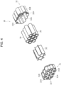
FIG. 4] FIG. 4 is an exploded perspective view of an electricity storage block. - [
FIG. 5] FIG. 5 is an exploded perspective view of an inter-block member. - [
FIG. 6] FIG. 6 is an exploded perspective view of a lid. - [
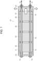
FIG. 7] FIG. 7 is a schematic view of an electricity storage pack according to another example of the embodiment. - [
FIG. 8] FIG. 8 is a schematic view of an electricity storage pack according to another example of the embodiment. - [
FIG. 9] FIG. 9 is a schematic view of an electricity storage pack according to another example of the embodiment. - [
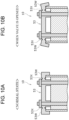
FIG. 10A] FIG. 10A is a schematic view of an electricity storage pack according to another example of the embodiment. - [
FIG. 10B] FIG. 10B is a schematic view of an electricity storage pack according to another example of the embodiment. - Hereinafter, an embodiment according to the present disclosure will be described with reference to the drawings. The shapes, materials, and the number of components described below are examples, and can be changed appropriately in accordance with the specification of an electricity storage module.
- With reference to
FIG. 1 to FIG. 4 ,electricity storage pack 10 according to an example of an embodiment will be described. -
Electricity storage pack 10 is mainly mounted in an electrically powered vehicle to supply electric power to a drive motor.Electricity storage pack 10 according to the present disclosure is used, for example, as a power source for electric bikes, assisted bicycles, electric wheelchairs, electric tricycles, electric carts, and the like. However, the present disclosure does not specify the usage ofelectricity storage pack 10, which can also be used as a power source for various electrical equipment used outdoors, such as power tools. -
Electricity storage pack 10 according to the present disclosure is capable of firmly fixinghousing 50 and at least oneelectricity storage block 20 to one other, as will be described in detail below. In addition,electricity storage pack 10 according to the present disclosure is capable of reducing the number of components. - As illustrated in
FIG. 1 to FIG. 3 ,electricity storage pack 10 includes a plurality ofelectricity storage blocks 20 each including a plurality ofcells 30,circuit board 40 in which a protection circuit that controls charging and discharging ofcells 30 is mounted, housing 50 that houses electricity storage blocks 20, fixingshafts 60 that penetrate one side face ofhousing 50 and at least oneelectricity storage block 20. In the following description, at least the direction in whichelectricity storage blocks 20 are aligned and in whichfixing shafts 60 extend is defined by a first direction. - As illustrated in
FIG. 2 to FIG. 4 ,electricity storage pack 10 includes a plurality ofelectricity storage blocks 20. In the present embodiment,electricity storage pack 10 includes fourelectricity storage blocks 20 that are connected in series in the longitudinal direction. However, the present disclosure is not limited to this embodiment. Inter-blockmember 21 is disposed between adjacent ones ofelectricity storage blocks 20. Inter-blockmember 21 includes a wall that separates adjacent ones ofelectricity storage blocks 20, a cushioning material, and the like. - Each of
electricity storage blocks 20 is a unit in which a plurality ofcells 30 are arranged in multi-tiers. Inelectricity storage block 20, a plurality ofcells 30 are arranged so that the longitudinal direction ofcells 30 is parallel to the first direction. -
Electricity storage block 20 includes a plurality ofcells 30,cell holders respective cells 30, andfiller 35 that fills the gaps betweencells 30. Inelectricity storage block 20 according to the present embodiment, tencells 30 are arranged in three rows of three, four, and three cells (three parallel units to be described below) in a hexagonal grid. -
Electricity storage block 20 may include a plurality of parallel units including a plurality ofcells 30. Here, in the parallel units, both end-face electrodes ofcells 30 may be connected in parallel via lead plates. In the parallel units,cells 30 may be arranged in a row. Adjacent parallel units may be arranged such that the polarities of the end-face electrodes ofcells 30 are opposite. Moreover, inelectricity storage block 20, adjacent parallel units may be connected in series. - Each of
cells 30 is, for example, a cylindrical lithium-ion secondary battery with end-face electrodes as described above.Cell 30 is not limited to the present embodiment, but may be other secondary batteries such as a nickel-metal hydride battery, nickel-cadmium battery, or lithium polymer battery, or other electricity storage devices such as a capacitor.Cell 30 is a cylindrical secondary battery, but the present disclosure is not limited to the embodiment.Cell 30 may be a square secondary battery. -
Cell 30 may include: an electrode group in which positive and negative electrodes are opposite to each other with a separator therebetween and are wound; a can that houses the electrode group together with electrolyte, and includes a tubular part and a bottom part that closes one end of the tubular part; and a sealing member that closes the opening at the other end of the can. The sealing member may be electrically connected to one of the positive electrode and the negative electrode via a lead or the like. The can may be electrically connected to the other of the positive electrode and the negative electrode via a lead or the like. At least one end ofcell 30 in the first direction may include an exhaust part. This configuration allows gas accumulated incell 30 to be discharged to the outside ofcell 30 and the outside ofelectricity storage block 20 via the exhaust part. The exhaust part may be a non-reversible valve that opens by breaking the imprint, or a reversible valve that forms an exhaust path by further compressing a compressed elastic material under gas pressure. In the first direction,cell 30 may include exhaust parts at both ends. - As illustrated in
FIG. 4 ,cell holders cells 30.Cell holder 31 holds one side ofcells 30 arranged in a hexagonal grid.Cell holder 31 includes holdingpart 31A andlateral wall 31B. In holdingpart 31A, tubular storage parts, with which one longitudinal end parts of arrangedcells 30 are respectively engaged, are integrally formed.Lateral wall 31B is formed along the outer periphery ofcells 30. Each of holdingpart 31A ofcell holder 31 and holdingpart 32A ofcell holder 32 includes a plurality of openings that penetrate therethrough in the first direction (longitudinal direction of cell 30). Current collection and gas exhaustion ofcells 30 are performed through the openings. -
Lateral wall 31B ofcell holder 31 includesholes 32H that penetratecell holder 31 in the longitudinal direction. Fixingshaft 60 is inserted intohole 32H.Hole 32H is engaged withspacer 21B ofinter-block member 21. Althoughholes 32H are provided at two positions, the present disclosure is not limited to the embodiment. The number ofholes 32H may correspond to the number of fixingshafts 60.Cell holder 31 may also includeinjection hole 31T into which a potting material is poured aftercells 30 are housed and assembled incell holders -
Cell holder 32 includes the same configuration ascell holder 31, and thus, the description thereof is omitted.Cell holder 31 andcell holder 32 are connected to each other by an engagement of an engagement part at the other longitudinal end oflateral wall 31B ofcell holder 31 with an engagement part at one longitudinal end oflateral wall 32B ofcell holder 32. -
Filler 35 fills the gaps betweencells 30 arranged inelectricity storage block 20.Filler 35 is disposed to fill the gaps betweencells 30 arranged in a hexagonal grid as described above. Althoughfiller 35 is made of a material with some elasticity, such as hard plastic or potting material,filler 35 is not limited to the present embodiment.Filler 35 may include a heat-absorbing material such as aluminum hydroxide. Whenfiller 35 is made of resin,filler 35 may be integral withcell holder 31. - As illustrated in
FIG. 5 ,inter-block member 21 defines the distance between two adjacent electricity storage blocks 20, forming a gap between two adjacent electricity storage blocks 20.Inter-block member 21 includes: plate-shapedcover 21A interposed between two adjacent electricity storage blocks 20 described above;spacers inter-block member 21 and are coupled withcell holders spacers 21C interposed betweencover 21A and each ofcell holders -
Cover 21A is arranged such that the thickness ofcover 21A is parallel to the first direction, and covers the openings ofcell holders cells 30 through the openings,cover 21A prevents the gas from reaching adjacentelectricity storage block 20. This preventscell holders cells 30 of adjacentelectricity storage block 20 from being thermally damaged due to the heat of the gas. A material with a high melting point is preferrable for the material ofcover 21A. Examples of the material with a high melting point include aluminum, copper, iron, and stainless steel. - Each
spacer 21B is tubular in shape that extends in the first direction. Both ends ofspacer 21B in the first direction have hollow protrusions that are engaged and coupled with throughholes 31H ofcell holder 31 and throughhole 31H ofcell holder 32. Fixingshaft 60 is inserted into the hollow part ofspacer 21B together with throughhole 31H. -
Spacer 21C is in a shape of a block. One end faces ofspacers 21C in the first direction are in contact withcover 21A, and the other end faces ofspacers 21C in the first direction are in contact with holdingparts cell holders spacer 21C may be arranged between adjacent ones of a plurality of openings of holdingparts Spacer 21C may partially overlap with the openings in the first direction. In the present embodiment, it may be that a plurality ofspacers 21C are disposed, some ofspacers 21C are arranged between a first main face ofcover 21A and oneelectricity storage block 20, and between a second main face (back side of the first main face) ofcover 21A and the otherelectricity storage block 20.Spacers 21C may be fixed to cover 21A with, for example, adhesive.Spacers 21C may be mechanically engaged withcover 21A. - Each of
spacers 21D is in a shape of plate that extends in the first direction. Eachspacer 21D includes protrusions at both ends in the first direction that are engaged withcell holders Cell holders spacers 21D. When part of the peripheral edge ofcover 21A is curved, the end face (main face) ofspacer 21D in a second direction perpendicular to the first direction may be a curved surface along the curve of the peripheral edge ofcover 21A. This curved surface contacting the curved peripheral edge ofcover 21A allows cover 21A to be fixed more firmly in the second direction. -
Spacers cover 21A (either the outer or inner peripheral edge) and do not overlap withcover 21A in the first direction. This configuration allowsspacers cover 21A in the second direction perpendicular to the first direction. -
Spacers cover 21A to move in the first direction.Spacers spacers 21C. In other words,spacers 21C are softer or have a lower Young's modulus or a lower elastic modulus thanspacers cell 30 to cover 21A, amongspacers 21C disposed on both main faces ofcover 21A,spacers 21C closer to the first main face where gas is discharged are pulled in the first direction, andspacers 21C closer to the second main face that is the back side of the first main face are compressed in the first direction. Thesespacers 21C and cover 21A are capable of increasing the distance in the first direction betweenelectricity storage block 20 that includescells 30, from which gas is blown, and cover 21A. This displacescover 21A in the first direction, widening the exhaust path aroundelectricity storage block 20 that discharges gas and prompting the gas exhaust to the outside ofelectricity storage pack 10. -
Spacers Spacers Spacer 21C may be made of an electrically insulating and elastic material.Spacer 21C may be made of, for example, chloroprene rubber or flame-retardant foam resin.Spacers 21C may be arranged in a compressed state under the force in the first direction when spacers 21C are arranged between two adjacent electricity storage blocks 20. Whether eachspacer 21C is arranged in a compressed state can be checked as described below. Whenelectricity storage pack 10 is disassembled and the sum of the dimensions of at least onespacer 21C after disassembly is larger than the sum of the dimensions of at least onespacer 21C aligned in the first direction before disassembly,spacer 21C can be considered to have been arranged between two electricity storage blocks 20 in a compressed state. - At least one of
spacers hole 31H instead of the outer peripheral edge ofcover 21A. Here, it is preferable that at least one ofspacers hole 31H in the first direction. It is also preferable thatspacers 21D surround cover 21A while being in close proximity to the edge ofcover 21A. However,spacers cover 21A. In two adjacent electricity storage blocks 20, the exhaust parts ofcells 30 may face toward onecommon inter-block member 21. This configuration can simplify the arrangement ofinter-block members 21. - As illustrated in
FIG. 2 andFIG. 3 , a protection circuit that controls charging and discharging ofcells 30 is mounted incircuit board 40 as described above. Electronic components that implement the protection circuit are mounted incircuit board 40.Circuit board 40 is in a shape of plate that extends along the longitudinal direction. In such a manner,circuit board 40 is disposed which extends along the lengthwise direction in whichcells 30 are connected in series. With this, the distance betweencircuit board 40 and eachcell 30 is short, facilitating wiring to eachcell 30 for detecting intermediate potentials and the like. - The protection circuit also includes a circuit that detects voltage of each of
cells 30 and interrupts charge and discharge current. When the voltage of any ofcells 30 becomes lower than the minimum voltage, the protection circuit interrupts the discharge current by turning off a switching device that interrupts the discharge current. When the voltage of any ofcells 30 becomes higher than the maximum voltage, the protection circuit stops charging by turning off a switching device that stops charging. In such a manner,electricity storage pack 10 can be used safely while protectingcells 30 by including the protection circuit that detects the voltage of each ofcells 30 and controls charging and discharging. - In addition,
circuit board 40 also includes a temperature detection circuit that detects temperature anomalies ofcells 30. The temperature detection circuit detects an abnormal rise in the temperature of eachcell 30 detected by a temperature sensor, and executes current control of discharging and charging ofcell 30, or stops charging and discharging ofcell 30.Electricity storage pack 10 may also include current collecting members that electrically connect electricity storage blocks 20 to one another. These current collector plates are adjacent to each other. - As illustrated in
FIG. 1 to FIG. 3 ,housing 50 houses electricity storage blocks 20, and also protects electricity storage blocks 20.Housing 50 includes:tubular body 51 with the longitudinal direction as the first direction; andlids body 51.Housing 50 may include a ring packing sandwiched between the openings ofbody 51 at both ends andlids body 51 with a waterproof structure.Housing 50 includes a pair oflids body 51 at both ends. However,body 51 may be in a bottomed tubular shape in which only one end face ofbody 51 is open and the end face opening is closed withonly lid 52. -
Body 51 is made of a metal, such as aluminum, which is strong and has excellent heat dissipation properties.Body 51 is in a rectangular tubular shape.Body 51 is in a square tubular shape with both end parts open.Body 51 may include a groove or a projection that extends along the longitudinal direction ofbody 51 to improve the strength. In addition, in order to insulatemetal body 51, the surface ofbody 51 may be covered with laminated film, vinyl, or the like. -
Lids Lids Lids holes 52H and 53H which fixingshafts 60 to be described below penetrate. Althoughholes 52H are provided at two positions and holes 53H are provided at two positions, the present disclosure is not limited to the present embodiment. The number ofholes 52H and 53H may correspond to the number of fixingshafts 60. One oflids cell 30 or a charge connector for chargingcell 30. - As illustrated in
FIG. 6 ,lid 52 includesframe body 52A withexhaust port 52B, a plurality ofporous bodies 52C thatclose exhaust port 52B, shieldingplate 52D interposed betweenporous body 52C andelectricity storage block 20 in the first direction,spacers 52E that are interposed betweenporous body 52C and shieldingplate 52D and define the distance betweenporous body 52C and shieldingplate 52D, screws 52F that penetrate the respective insertion holes offrame body 52A,porous bodies 52C,spacers 52E and shieldingplate 52D, andnuts 52G fastened to one longitudinal ends ofscrews 52F. -
Frame body 52A may be made of hard plastic or metal.Frame body 52A includesholes 52H which fixingshafts 60 penetrate and insertion holes which screws 52F penetrate. Four insertion holes are provided for fourscrews 52F. However, the number of insertion holes and the number ofscrews 52F are not limited to such an example. - Each of
porous bodies 52C may be, for example, a perforated metal with numerous through-holes in an aluminum sheet.Electricity storage pack 10 includes twoporous bodies 52C forframe body 52A.Porous bodies 52C prevent the contents ofcells 30 from being discharged along with gas to the outside ofelectricity storage pack 10. Moreover, as the gas passes throughporous bodies 52C, heat from the gas is transferred toporous bodies 52C, allowing the gas having passed to be cooled. Only oneporous body 52C may be provided. -
Shielding plate 52D is interposed betweenelectricity storage block 20 closest tolid 52 andporous bodies 52C in the first direction.Shielding plate 52D is capable of blocking the gas discharged fromcells 30 ofelectricity storage block 20 and preventing hot gas from blowing directly ontoporous bodies 52C.Shielding plate 52D may be made of a material with a higher melting point thanporous body 52C. For example, shieldingplate 52D may be made of steel, stainless steel, or ceramics. -
Spacers 52E form a gap betweenporous body 52C and shieldingplate 52D. A spacing betweenspacers 52E defines the exhaust path that allows gas to enter the gap. Eachspacer 52E is tubular, and screw 52F penetrates the hollow part ofspacer 52E. Fourspacers 52E are provided corresponding to the number ofscrews 52F. However, the number ofspacers 52E is not limited to four. - Each
screw 52F includes a screw head at one end, and is fastened tonut 52G at the other end.Screw 52F andnut 52G may be made of hard plastic or metal. In a similar manner tolid 52,lid 53 may also include a frame body, porous bodies, a shielding plate, spacers, screws, and nuts.Lid 53 may be made of only a frame body with no exhaust port. - As illustrated in
FIG. 1 to FIG. 3 , each of fixingshafts 60 is a shaft that penetrateshousing 50 and four electricity storage blocks 20 to fasten and fixhousing 50 and four electricity storage blocks 20 along the longitudinal direction. More specifically, fixingshaft 60 penetrateslids housing 50 andcell holders shafts 60 are capable of firmly fixinghousing 50 and electricity storage blocks 20 to one another. In addition, fixingshafts 60 reduces the number of components inelectricity storage pack 10. - Fixing
shaft 60 includesrod 61 that penetrateslids housing 50 andcell holders fixtures 62 that fix both ends ofrod 61 tolids housing 50.Rod 61 is a metal shaft with screw parts at both ends and has a length that penetrateshousing 50 in the first direction.Fixtures 62 are nuts, which press against the end faces oflids shafts 60 are not limited to the above configuration, but may include a rod made of a metal shaft and fixtures, such as a push nut or E-ring. - Fixing
shaft 60 is not limited to the present embodiment. Fixingshaft 60 may penetrate at least oneelectricity storage block 20 and onelid 52 to fixelectricity storage block 20 andhousing 50. In such a configuration, a separate fixing shaft to fix the electricity storage blocks to one another and a separate fixing shaft to fixelectricity storage block 20 and theother lid 53 are required. Moreover, fixingshaft 60 may penetrate all electricity storage blocks 20 and onelid 52 to fix electricity storage blocks 20 andhousing 50. In such a configuration, a separate fixing shaft to fixelectricity storage block 20 and theother lid 53 is required. - Fixing
shaft 60 is not limited to the present embodiment, but may be configured to penetrate at least oneelectricity storage block 20 andbody 51 to fixelectricity storage block 20 andhousing 50. - With
electricity storage pack 10 according to the present disclosure, storage blocks 20 andhousing 50 are fixed penetrating at least oneelectricity storage block 20 and onelid 52, so that electricity storage blocks 20 andhousing 50 can be firmly fixed. Moreover, the number of components can be reduced compared to an electricity storage pack that includes fixing shafts to fix electricity storage blocks 20 to one another and fixtures to fixlids cell holders - With reference to
FIG. 7 to FIG. 10B ,electricity storage pack 10 according to another example of the embodiment will be described. In the following description, components that are different from or added toelectricity storage pack 10 described above will be described with different reference numerals. The components that are the same as those inelectricity storage pack 10 described above will be described with the same reference numerals and their descriptions will be omitted. - As illustrated in
FIG. 7 ,electricity storage pack 10 includes fixingshafts 70 that extend along the axis ofelectricity storage pack 10 when the internal pressure ofhousing 50 reaches at least a predetermined pressure. More specifically, each fixingshaft 70 includesrod 71 that is plastically deformed along the axis when pulled at a predetermined pressure or higher.Rod 71 may include a reduced-diameter part that is plastically deformed along the axis when pulled at a predetermined pressure or higher. - With the above configuration, when the internal pressure of
housing 50 increases due to the pressure of the gas discharged from the inside ofcell 30 during malfunction ofcell 30, causing high pressure to act onlids housing 50, the axial extension of fixingshaft 70 separatesbody 51 from thelids body 51 andlids housing 50 to be discharged to the outside.Lids body 51 ofhousing 50. The configuration regulates the direction of displacement oflids rod 71 is deformed, allowingelectricity storage pack 10 to be sealed again after the completion of gas discharge. - As illustrated in
FIG. 8 , inelectricity storage pack 10, fixingshafts 60 andlids housing 50 are fixed to one another viaspring washers 63 as elastic members. More precisely,spring washers 63 are disposed betweenfixtures 62 of fixingshafts 60 andlids spring washer 63 always axiallybiases fixture 62, and contracts when force against the biasing force is applied.Spring washer 63 may be a conical spring washer. - With the above configuration, when the internal pressure of
housing 50 increases due to the pressure of gas discharged from the inside ofcell 30 during malfunction ofcell 30, causing high pressure to act onlids housing 50,spring washers 63 contract, separatingbody 51 fromlids body 51 andlids housing 50 to be discharged to the outside. - As illustrated in
FIG. 9 , inelectricity storage pack 10,lid 52 has edge part 52W with a thickness that is smaller than the thickness oflid 52 excluding edge part 52W. - With the above configuration, when the internal pressure of
housing 50 increases due to the pressure of the gas discharged from the inside ofcell 30 during malfunction ofcell 30, causing high pressure to act onlids housing 50, the plastic deformation ofedge part 53W outward in the longitudinal direction generates a gap betweenbody 51 andlid 52. This allows the gas insidehousing 50 to be discharged to the outside. - As illustrated in
FIG. 10A , in the second direction, groove-shapedthin part 53X along the shape ofedge part 53W may be disposed inside relative to edgepart 53W of frame body 53A. This allowslid 52 to be opened by displacing the region fromthin part 53X to edgepart 53W as illustrated inFIG. 10B . In this case, the peripheral edge ofedge part 53W may include a wall-shaped flared part that extends towardbody 51. This flared part stabilizes the arrangement oflid 53 relative tobody 51. - The present invention is not limited to the above-described embodiment and variations thereof. It is of course possible that various changes and modifications are made within the scope of matters described in the claims of the present application.
-
- 10
- electricity storage pack
- 20
- electricity storage block
- 21
- inter-block member
- 21A
- cover
- 21B
- spacer
- 21C
- spacer
- 21D
- spacer
- 30
- cell
- 31
- cell holder
- 31A
- holding part
- 31B
- lateral wall
- 31H
- hole
- 31T
- injection hole
- 32
- cell holder
- 32B
- lateral wall
- 32H
- hole
- 35
- filler
- 40
- circuit board
- 50
- housing
- 51
- body
- 52
- lid
- 52A
- frame body
- 52B
- exhaust port
- 52C
- porous body
- 52D
- shielding plate
- 52E
- spacer
- 52G
- screw
- 52F
- nut
- 52H
- hole
- 53
- lid
- 53H
- hole
- 53W
- edge part
- 53X
- thin part
- 60
- fixing shaft
- 61
- rod
- 62
- fixture
- 63
- spring washer
- 70
- fixing shaft
- 71
- rod
Claims (16)
- An electricity storage pack comprising:at least one electricity storage block that includes a plurality of cells; anda housing that houses the at least one electricity storage block,wherein the at least one electricity storage block and the housing are fixed to a fixing shaft that is elongated in a first direction and penetrates a first side face of the housing and the at least one electricity storage block.
- The electricity storage pack according to claim 1,
wherein the fixing shaft penetrates the first side face and a second side face of the housing in the first direction. - The electricity storage pack according to claim 1 or claim 2, comprisinga cell holder that holds the plurality of cells,wherein the fixing shaft penetrates an insertion hole of the cell holder.
- The electricity storage pack according to claim 1,wherein the at least one electricity storage block comprises a plurality of electricity storage blocks, andthe plurality of electricity storage blocks are arranged in the first direction.
- The electricity storage pack according to claim 4,wherein each of the plurality of electricity storage blocks includes an insertion hole,the insertion holes of the plurality of electricity storage blocks overlap with each other in the first direction, andthe fixing shaft penetrates the insertion holes.
- The electricity storage pack according to claim 4 or claim 5, comprising
an inter-block member between two adjacent ones of the plurality of electricity storage blocks in the first direction with a gap between the two adjacent ones of the plurality of electricity storage blocks. - The electricity storage pack according to claim 6,
wherein the inter-block member includes a cover that is plate-shaped, a first spacer that is disposed along an edge of the cover and connects the two adjacent ones of the plurality of electricity storage blocks, and a second spacer that is interposed between the cover and the two adjacent ones of the plurality of electricity storage blocks. - The electricity storage pack according to claim 7,wherein the first spacer includes a rigidity higher than a rigidity of the second spacer, andthe first spacer does not overlap with the cover in the first direction.
- The electricity storage pack according to claim 7 or claim 8,
wherein the second spacer is disposed in a compressed state between the cover and the at least one electricity storage block. - The electricity storage pack according to any one of claims 7 to 9, comprisinga cell holder that holds the plurality of cells,wherein, in the cell holder, the plurality of cells are arranged in a second direction perpendicular to the first direction,each of the plurality of cells includes an exhaust part at one end of the cell in the first direction, andthe exhaust part opposes the cover in the first direction.
- The electricity storage pack according to any one of claims 1 to 10,wherein the housing includes a body in a tubular shape and a lid that closes each of end parts of the body, andthe fixing shaft penetrates the lid.
- The electricity storage pack according to claim 11,
wherein the lid includes:a vent;a porous body that closes the vent; anda shielding plate that is interposed between the porous body and the at least one electricity storage block in the first direction. - The electricity storage pack according to claim 12, comprisinga third spacer that is disposed between the porous body and the shielding plate,wherein a gap is provided between the porous body and the shielding plate.
- The electricity storage pack according to any one of claims 11 to 13,
wherein, when an internal pressure of the housing is a predetermined pressure or higher, a gap is generated between the body and the lid by an extension of the fixing shaft along an axis of the fixing shaft. - The electricity storage pack according to any one of claims 11 to 13,wherein the lid is fixed to the fixing shaft via an elastic member, andwhen an internal pressure of the housing is a predetermined pressure or higher, a gap is generated between the body and the lid against a biasing force applied by the elastic member.
- The electricity storage pack according to any one of claims 11 to 13,wherein the lid includes an edge part with an axial thickness that is smaller than an axial thickness of the lid excluding the edge part, the edge part being on an outer side relative to a part of the lid where the fixing shaft penetrates, andwhen an internal pressure of the housing is a predetermined pressure or higher, a gap is generated between the body and the lid by deformation of the edge part.
Applications Claiming Priority (2)
| Application Number | Priority Date | Filing Date | Title |
|---|---|---|---|
| JP2021213403 | 2021-12-27 | ||
| PCT/JP2022/046262 WO2023127531A1 (en) | 2021-12-27 | 2022-12-15 | Electricity storage pack |
Publications (2)
| Publication Number | Publication Date |
|---|---|
| EP4459762A1 true EP4459762A1 (en) | 2024-11-06 |
| EP4459762A4 EP4459762A4 (en) | 2025-04-23 |
Family
ID=86998731
Family Applications (1)
| Application Number | Title | Priority Date | Filing Date |
|---|---|---|---|
| EP22915755.7A Pending EP4459762A4 (en) | 2021-12-27 | 2022-12-15 | ELECTRICITY STORAGE BLOCK |
Country Status (5)
| Country | Link |
|---|---|
| US (1) | US20250055103A1 (en) |
| EP (1) | EP4459762A4 (en) |
| JP (1) | JPWO2023127531A1 (en) |
| CN (1) | CN118525414A (en) |
| WO (1) | WO2023127531A1 (en) |
Families Citing this family (2)
| Publication number | Priority date | Publication date | Assignee | Title |
|---|---|---|---|---|
| DE102024209185A1 (en) * | 2024-09-24 | 2026-03-26 | Robert Bosch Gesellschaft mit beschränkter Haftung | Battery arrangement for a pedal-powered vehicle and pedal-powered vehicle with battery arrangement |
| DE102024209183A1 (en) * | 2024-09-24 | 2026-03-26 | Robert Bosch Gesellschaft mit beschränkter Haftung | Battery arrangement for a pedal-powered vehicle and pedal-powered vehicle with battery arrangement |
Family Cites Families (10)
| Publication number | Priority date | Publication date | Assignee | Title |
|---|---|---|---|---|
| JP5311915B2 (en) * | 2008-07-29 | 2013-10-09 | 三洋電機株式会社 | Battery pack for vehicle power supply |
| JP5496746B2 (en) * | 2010-03-31 | 2014-05-21 | 三洋電機株式会社 | Battery pack |
| CN104078630B (en) * | 2009-12-24 | 2017-02-08 | 三洋电机株式会社 | Battery pack |
| KR101191657B1 (en) * | 2010-07-19 | 2012-10-17 | 에스비리모티브 주식회사 | Battery module |
| JP5944204B2 (en) | 2012-04-10 | 2016-07-05 | 三洋電機株式会社 | Battery pack |
| DE102013100545B4 (en) * | 2013-01-18 | 2022-12-01 | Cayago Tec Gmbh | Watercraft with an accumulator unit |
| JP5708784B2 (en) * | 2013-07-04 | 2015-04-30 | 株式会社豊田自動織機 | Battery pack |
| CN206282904U (en) * | 2016-12-15 | 2017-06-27 | 深圳市伟创源科技有限公司 | Lithium battery and scooter |
| JP7096745B2 (en) * | 2018-09-19 | 2022-07-06 | 豊田合成株式会社 | Mobile battery pack system |
| JP7079415B2 (en) * | 2019-03-08 | 2022-06-02 | トヨタ自動車株式会社 | Batteries assembled |
-
2022
- 2022-12-15 US US18/722,244 patent/US20250055103A1/en active Pending
- 2022-12-15 WO PCT/JP2022/046262 patent/WO2023127531A1/en not_active Ceased
- 2022-12-15 CN CN202280083774.8A patent/CN118525414A/en active Pending
- 2022-12-15 EP EP22915755.7A patent/EP4459762A4/en active Pending
- 2022-12-15 JP JP2023570844A patent/JPWO2023127531A1/ja active Pending
Also Published As
| Publication number | Publication date |
|---|---|
| CN118525414A (en) | 2024-08-20 |
| US20250055103A1 (en) | 2025-02-13 |
| WO2023127531A1 (en) | 2023-07-06 |
| JPWO2023127531A1 (en) | 2023-07-06 |
| EP4459762A4 (en) | 2025-04-23 |
Similar Documents
| Publication | Publication Date | Title |
|---|---|---|
| EP2654100B1 (en) | Battery pack | |
| EP3926732B1 (en) | Battery module | |
| KR101058102B1 (en) | Battery pack | |
| US20090239137A1 (en) | Battery module and battery pack | |
| CN113991231B (en) | Battery Pack | |
| KR100590045B1 (en) | Assembling Method of Secondary Battery and Secondary Battery | |
| US20140220396A1 (en) | Battery pack | |
| US20210313637A1 (en) | Battery module | |
| US20120263995A1 (en) | Battery module and battery pack | |
| JP2018129251A (en) | Battery pack | |
| EP4459762A1 (en) | Electricity storage pack | |
| EP3363063B1 (en) | Batterey terminal comprising an integrated spring or a flexible pad | |
| US20240120604A1 (en) | Power supply device | |
| US9356326B2 (en) | Top cover and battery pack having the same | |
| EP3890048A1 (en) | Battery module | |
| CN118077090A (en) | Power supply device and method for manufacturing the same | |
| US12244034B2 (en) | Buffer member and electrical storage module | |
| WO2022071759A1 (en) | Secondary battery and device including same | |
| CN119301810A (en) | Power storage module | |
| US20120208065A1 (en) | Single Cell For a Battery | |
| JP4822760B2 (en) | Power supply | |
| KR102926474B1 (en) | Battery pack and vehicle including same | |
| KR20080010156A (en) | Battery module | |
| JP2006190611A (en) | Power supply device | |
| JP7680118B2 (en) | Battery pack with improved shock resistance |
Legal Events
| Date | Code | Title | Description |
|---|---|---|---|
| STAA | Information on the status of an ep patent application or granted ep patent |
Free format text: STATUS: THE INTERNATIONAL PUBLICATION HAS BEEN MADE |
|
| PUAI | Public reference made under article 153(3) epc to a published international application that has entered the european phase |
Free format text: ORIGINAL CODE: 0009012 |
|
| STAA | Information on the status of an ep patent application or granted ep patent |
Free format text: STATUS: REQUEST FOR EXAMINATION WAS MADE |
|
| 17P | Request for examination filed |
Effective date: 20240712 |
|
| AK | Designated contracting states |
Kind code of ref document: A1 Designated state(s): AL AT BE BG CH CY CZ DE DK EE ES FI FR GB GR HR HU IE IS IT LI LT LU LV MC ME MK MT NL NO PL PT RO RS SE SI SK SM TR |
|
| DAV | Request for validation of the european patent (deleted) | ||
| DAX | Request for extension of the european patent (deleted) | ||
| A4 | Supplementary search report drawn up and despatched |
Effective date: 20250324 |
|
| RIC1 | Information provided on ipc code assigned before grant |
Ipc: H01M 50/264 20210101ALI20250318BHEP Ipc: H01M 50/258 20210101ALI20250318BHEP Ipc: H01M 50/244 20210101ALI20250318BHEP Ipc: H01M 50/392 20210101ALI20250318BHEP Ipc: H01M 50/367 20210101ALI20250318BHEP Ipc: H01M 50/35 20210101ALI20250318BHEP Ipc: H01M 50/342 20210101ALI20250318BHEP Ipc: H01M 50/325 20210101ALI20250318BHEP Ipc: H01M 50/317 20210101ALI20250318BHEP Ipc: H01M 50/289 20210101ALI20250318BHEP Ipc: H01M 50/271 20210101ALI20250318BHEP Ipc: H01M 50/242 20210101ALI20250318BHEP Ipc: H01G 11/78 20130101ALI20250318BHEP Ipc: H01G 11/12 20130101ALI20250318BHEP Ipc: H01M 50/213 20210101AFI20250318BHEP |
|
| STAA | Information on the status of an ep patent application or granted ep patent |
Free format text: STATUS: EXAMINATION IS IN PROGRESS |
|
| 17Q | First examination report despatched |
Effective date: 20260331 |