EP4459746A1 - Heat transfer member - Google Patents
Heat transfer member Download PDFInfo
- Publication number
- EP4459746A1 EP4459746A1 EP22915265.7A EP22915265A EP4459746A1 EP 4459746 A1 EP4459746 A1 EP 4459746A1 EP 22915265 A EP22915265 A EP 22915265A EP 4459746 A1 EP4459746 A1 EP 4459746A1
- Authority
- EP
- European Patent Office
- Prior art keywords
- heat transfer
- transfer member
- protrusions
- cooling fluid
- heat
- Prior art date
- Legal status (The legal status is an assumption and is not a legal conclusion. Google has not performed a legal analysis and makes no representation as to the accuracy of the status listed.)
- Withdrawn
Links
Images


Classifications
-
- F—MECHANICAL ENGINEERING; LIGHTING; HEATING; WEAPONS; BLASTING
- F28—HEAT EXCHANGE IN GENERAL
- F28F—DETAILS OF HEAT-EXCHANGE AND HEAT-TRANSFER APPARATUS, OF GENERAL APPLICATION
- F28F3/00—Plate-like or laminated elements; Assemblies of plate-like or laminated elements
- F28F3/12—Elements constructed in the shape of a hollow panel, e.g. with channels
-
- F—MECHANICAL ENGINEERING; LIGHTING; HEATING; WEAPONS; BLASTING
- F28—HEAT EXCHANGE IN GENERAL
- F28F—DETAILS OF HEAT-EXCHANGE AND HEAT-TRANSFER APPARATUS, OF GENERAL APPLICATION
- F28F3/00—Plate-like or laminated elements; Assemblies of plate-like or laminated elements
- F28F3/02—Elements or assemblies thereof with means for increasing heat-transfer area, e.g. with fins, with recesses, with corrugations
- F28F3/022—Elements or assemblies thereof with means for increasing heat-transfer area, e.g. with fins, with recesses, with corrugations the means being wires or pins
-
- F—MECHANICAL ENGINEERING; LIGHTING; HEATING; WEAPONS; BLASTING
- F28—HEAT EXCHANGE IN GENERAL
- F28D—HEAT-EXCHANGE APPARATUS, NOT PROVIDED FOR IN ANOTHER SUBCLASS, IN WHICH THE HEAT-EXCHANGE MEDIA DO NOT COME INTO DIRECT CONTACT
- F28D9/00—Heat-exchange apparatus having stationary plate-like or laminated conduit assemblies for both heat-exchange media, the media being in contact with different sides of a conduit wall
- F28D9/0031—Heat-exchange apparatus having stationary plate-like or laminated conduit assemblies for both heat-exchange media, the media being in contact with different sides of a conduit wall the conduits for one heat-exchange medium being formed by paired plates touching each other
- F28D9/0043—Heat-exchange apparatus having stationary plate-like or laminated conduit assemblies for both heat-exchange media, the media being in contact with different sides of a conduit wall the conduits for one heat-exchange medium being formed by paired plates touching each other the plates having openings therein for circulation of at least one heat-exchange medium from one conduit to another
- F28D9/005—Heat-exchange apparatus having stationary plate-like or laminated conduit assemblies for both heat-exchange media, the media being in contact with different sides of a conduit wall the conduits for one heat-exchange medium being formed by paired plates touching each other the plates having openings therein for circulation of at least one heat-exchange medium from one conduit to another the plates having openings therein for both heat-exchange media
-
- F—MECHANICAL ENGINEERING; LIGHTING; HEATING; WEAPONS; BLASTING
- F28—HEAT EXCHANGE IN GENERAL
- F28F—DETAILS OF HEAT-EXCHANGE AND HEAT-TRANSFER APPARATUS, OF GENERAL APPLICATION
- F28F1/00—Tubular elements; Assemblies of tubular elements
- F28F1/10—Tubular elements and assemblies thereof with means for increasing heat-transfer area, e.g. with fins, with projections, with recesses
- F28F1/40—Tubular elements and assemblies thereof with means for increasing heat-transfer area, e.g. with fins, with projections, with recesses the means being only inside the tubular element
- F28F1/405—Tubular elements and assemblies thereof with means for increasing heat-transfer area, e.g. with fins, with projections, with recesses the means being only inside the tubular element and being formed of wires
-
- F—MECHANICAL ENGINEERING; LIGHTING; HEATING; WEAPONS; BLASTING
- F28—HEAT EXCHANGE IN GENERAL
- F28F—DETAILS OF HEAT-EXCHANGE AND HEAT-TRANSFER APPARATUS, OF GENERAL APPLICATION
- F28F3/00—Plate-like or laminated elements; Assemblies of plate-like or laminated elements
- F28F3/02—Elements or assemblies thereof with means for increasing heat-transfer area, e.g. with fins, with recesses, with corrugations
- F28F3/04—Elements or assemblies thereof with means for increasing heat-transfer area, e.g. with fins, with recesses, with corrugations the means being integral with the element
-
- F—MECHANICAL ENGINEERING; LIGHTING; HEATING; WEAPONS; BLASTING
- F28—HEAT EXCHANGE IN GENERAL
- F28F—DETAILS OF HEAT-EXCHANGE AND HEAT-TRANSFER APPARATUS, OF GENERAL APPLICATION
- F28F3/00—Plate-like or laminated elements; Assemblies of plate-like or laminated elements
- F28F3/02—Elements or assemblies thereof with means for increasing heat-transfer area, e.g. with fins, with recesses, with corrugations
- F28F3/04—Elements or assemblies thereof with means for increasing heat-transfer area, e.g. with fins, with recesses, with corrugations the means being integral with the element
- F28F3/042—Elements or assemblies thereof with means for increasing heat-transfer area, e.g. with fins, with recesses, with corrugations the means being integral with the element in the form of local deformations of the element
- F28F3/044—Elements or assemblies thereof with means for increasing heat-transfer area, e.g. with fins, with recesses, with corrugations the means being integral with the element in the form of local deformations of the element the deformations being pontual, e.g. dimples
-
- F—MECHANICAL ENGINEERING; LIGHTING; HEATING; WEAPONS; BLASTING
- F28—HEAT EXCHANGE IN GENERAL
- F28F—DETAILS OF HEAT-EXCHANGE AND HEAT-TRANSFER APPARATUS, OF GENERAL APPLICATION
- F28F3/00—Plate-like or laminated elements; Assemblies of plate-like or laminated elements
- F28F3/02—Elements or assemblies thereof with means for increasing heat-transfer area, e.g. with fins, with recesses, with corrugations
- F28F3/04—Elements or assemblies thereof with means for increasing heat-transfer area, e.g. with fins, with recesses, with corrugations the means being integral with the element
- F28F3/042—Elements or assemblies thereof with means for increasing heat-transfer area, e.g. with fins, with recesses, with corrugations the means being integral with the element in the form of local deformations of the element
- F28F3/046—Elements or assemblies thereof with means for increasing heat-transfer area, e.g. with fins, with recesses, with corrugations the means being integral with the element in the form of local deformations of the element the deformations being linear, e.g. corrugations
-
- F—MECHANICAL ENGINEERING; LIGHTING; HEATING; WEAPONS; BLASTING
- F28—HEAT EXCHANGE IN GENERAL
- F28F—DETAILS OF HEAT-EXCHANGE AND HEAT-TRANSFER APPARATUS, OF GENERAL APPLICATION
- F28F3/00—Plate-like or laminated elements; Assemblies of plate-like or laminated elements
- F28F3/02—Elements or assemblies thereof with means for increasing heat-transfer area, e.g. with fins, with recesses, with corrugations
- F28F3/06—Elements or assemblies thereof with means for increasing heat-transfer area, e.g. with fins, with recesses, with corrugations the means being attachable to the element
-
- F—MECHANICAL ENGINEERING; LIGHTING; HEATING; WEAPONS; BLASTING
- F28—HEAT EXCHANGE IN GENERAL
- F28F—DETAILS OF HEAT-EXCHANGE AND HEAT-TRANSFER APPARATUS, OF GENERAL APPLICATION
- F28F3/00—Plate-like or laminated elements; Assemblies of plate-like or laminated elements
- F28F3/08—Elements constructed for building-up into stacks, e.g. capable of being taken apart for cleaning
-
- H—ELECTRICITY
- H01—ELECTRIC ELEMENTS
- H01M—PROCESSES OR MEANS, e.g. BATTERIES, FOR THE DIRECT CONVERSION OF CHEMICAL ENERGY INTO ELECTRICAL ENERGY
- H01M10/00—Secondary cells; Manufacture thereof
- H01M10/60—Heating or cooling; Temperature control
- H01M10/61—Types of temperature control
- H01M10/613—Cooling or keeping cold
-
- H—ELECTRICITY
- H01—ELECTRIC ELEMENTS
- H01M—PROCESSES OR MEANS, e.g. BATTERIES, FOR THE DIRECT CONVERSION OF CHEMICAL ENERGY INTO ELECTRICAL ENERGY
- H01M10/00—Secondary cells; Manufacture thereof
- H01M10/60—Heating or cooling; Temperature control
- H01M10/65—Means for temperature control structurally associated with the cells
- H01M10/653—Means for temperature control structurally associated with the cells characterised by electrically insulating or thermally conductive materials
-
- H—ELECTRICITY
- H01—ELECTRIC ELEMENTS
- H01M—PROCESSES OR MEANS, e.g. BATTERIES, FOR THE DIRECT CONVERSION OF CHEMICAL ENERGY INTO ELECTRICAL ENERGY
- H01M10/00—Secondary cells; Manufacture thereof
- H01M10/60—Heating or cooling; Temperature control
- H01M10/65—Means for temperature control structurally associated with the cells
- H01M10/655—Solid structures for heat exchange or heat conduction
- H01M10/6551—Surfaces specially adapted for heat dissipation or radiation, e.g. fins or coatings
-
- H—ELECTRICITY
- H01—ELECTRIC ELEMENTS
- H01M—PROCESSES OR MEANS, e.g. BATTERIES, FOR THE DIRECT CONVERSION OF CHEMICAL ENERGY INTO ELECTRICAL ENERGY
- H01M10/00—Secondary cells; Manufacture thereof
- H01M10/60—Heating or cooling; Temperature control
- H01M10/65—Means for temperature control structurally associated with the cells
- H01M10/655—Solid structures for heat exchange or heat conduction
- H01M10/6556—Solid parts with flow channel passages or pipes for heat exchange
-
- H—ELECTRICITY
- H01—ELECTRIC ELEMENTS
- H01M—PROCESSES OR MEANS, e.g. BATTERIES, FOR THE DIRECT CONVERSION OF CHEMICAL ENERGY INTO ELECTRICAL ENERGY
- H01M10/00—Secondary cells; Manufacture thereof
- H01M10/60—Heating or cooling; Temperature control
- H01M10/65—Means for temperature control structurally associated with the cells
- H01M10/656—Means for temperature control structurally associated with the cells characterised by the type of heat-exchange fluid
- H01M10/6567—Liquids
Definitions
- the present invention relates to a heat transfer member that is used in a heat exchanger.
- a prior-art heat transfer member is described in, for example, Patent Citation 1.
- the heat transfer member (heat exchange tube) described in Patent Citation 1 has obliquely protruding parts formed obliquely along the flow direction of a heat exchange fluid on at least one of a pair of opposing surfaces (walls).
- the obliquely protruding parts are formed by press working so as to have a protuberant form on one of the opposing surfaces (walls) and have a recessed form on the other.
- the obliquely protruding parts of the heat transfer member generate a longitudinal vortex in a flow channel for the heat exchange fluid and improve heat exchange efficiency while minimizing any increase in resistance due to the generation of a turbulent flow.
- Patent Citation 1 WO 2020-013292
- the present invention was devised in view of the above problems with the prior art, it being an object of the invention to provide a heat transfer member with which manufacturing costs can be reduced and heat transfer performance can be improved.
- the other main surface is flat, when a heating element is placed on the other main surface side or a heating element is placed on the other main surface with a heat conductive material interposed therebetween, heat is transferred uniformly between the heating element and the entire other main surface.
- the protrusions can be formed by, for example, forging, metal wire overlay, metal 3D printing, resin processing, or the like, which allows the total extension dimension to be reduced and material to be saved because the apex angle of the wave protruding parts is an obtuse angle.
- a turbulent flow is generated by the protrusions and the cooling fluid is stirred behind the protrusions.
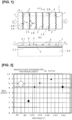
- a heat transfer member 1 shown in Fig. 1(A) is a rectangular plate-form member that is used in a heat exchanger.
- the heat transfer member 1 as shown in Fig. 1(B) , one main surface disposed facing a flow channel C for a cooling fluid is provided with protrusions 2 that extend in a direction perpendicular to a direction F of flow of the cooling fluid, and another main surface is flat.
- a direction along a long side is the direction F of flow of the cooling fluid
- a direction along a short side is a direction perpendicular to the flow direction F, i.e., a width direction of the flow channel C.
- the flow channel C is formed between one main surface of the heat transfer member 1 and a flow channel formation member 21 that faces this main surface, and a side portion (not shown) is closed.
- Another main surface of the heat transfer member 1 is placed on a heating element 23, with a heat conductive layer 22 made of a heat conductive material interposed therebetween.
- the protrusions 2 of the heat transfer member 1 described above have an undulating profile in plan view, and undulating convex portions 2A with an apex angle ⁇ t facing opposite to the flow direction of the cooling fluid is in a range greater than 105° and less than 180°.
- the apex angle ⁇ t of the undulating convex portions 2A is preferably in a range greater than 110° and less than 170°.
- the protrusions 2 of this embodiment have a zigzag profile, which is an example of an undulating profile, and an angle formed by adjacent sides is in a range greater than 105° and less than 180°, this angle being the same between all adjacent sides in the illustrated example.
- the protrusions 2 can be formed by, for example, forging, metal wire overlay, metal 3D printing, resin processing, or the like.
- the total extension dimension is relatively large, and the amount of heat exchanged per length is relatively low.
- the total extension dimension is the same as the width dimension of the heat transfer member 1, and the amount of heat exchanged per length is relatively low.
- the amount of heat exchanged per length becomes relatively large while the total extension dimension is kept short due to the apex angle ⁇ t of the undulating convex portions 2A of the protrusions 2 being in a range greater than 105° and less than 180°, and preferably in a range greater than 110° and less than 170°.
- the protrusions 2 are formed continuously in a range extending from one end to another end of the heat transfer member in a direction (Y direction) that is perpendicular to the flow direction F (X direction) of the cooling fluid.
- the protrusions 2 have, alternately, a plurality of undulating convex portions 2A and a plurality of undulating concave portions 2B on a surface facing opposite to the flow direction F.
- the recessed and protruding parts are reversed between the upstream and downstream sides of the flow direction F, but in particular, the recessed and protruding parts on the upstream-side surface are designated as the undulating convex portions 2A and the undulating concave portions 2B.
- Fig. 3 is a graph of a rate of improvement in the amount of exchanged heat when the width Tw of the protrusions 2 is varied, where a case of no protrusions 2 (flat) is denoted as 100%.
- the rate of improvement in the amount of heat exchanged tends to decrease slightly as the width Tw of the protrusions 2 increases, but it has been found that the amount of heat exchanged is clearly improved by the protrusions 2; in particular, setting the width Tw of the protrusions 2 to 2 mm or less causes the amount of heat exchanged to become relatively large.
- the heat transfer member 1 in the illustrated example has a plurality of protrusions 2 (six in the drawings) at predetermined intervals in the flow direction F (X direction) of the cooling fluid, and as shown by line L in Fig. 1 , the protrusions 2 are arranged such that the respective undulating convex portions 2A are aligned in the direction F of flow of the cooling fluid.
- the protrusions 2 in the illustrated example are arranged at a constant pitch P, but can be arranged at appropriate intervals depending on the apex angle ⁇ t, the width Tw, etc.
- Fig. 4 is a graph of the rate of improvement in the amount of heat exchanged when the protrusions 2 are aligned (middle of the graph) and when the protrusions 2 are offset (right side of the graph), where a case devoid of protrusions 2 (flat) is denoted as 100%.
- the heat exchange rate improves in either case, and it is also understood that offsetting the undulating convex portions 2A yields a relatively greater amount of heat exchanged than aligning the undulating convex portions 2A.
- Fig. 5 is a graph of the rate of improvement in the amount of heat exchanged when a height of the protrusions 2 is varied, where a case of no protrusions 2 (flat) is denoted as 100%.
- the amount of heat exchanged is improved regardless of the height of the protrusions 2; in particular, it is understood that setting the height of the protrusions 2 to 0.5 to 10 mm (inclusive) causes the amount of heat exchanged to become relatively large.
- a Reynolds number Re of the cooling fluid flowing through the flow channel C is 2000 or less. Comparing heat transfer members 1 having undulating protrusions and linear protrusions to a heat transfer member 1 having no protrusions indicates that the amount of heat exchanged becomes large due to the protrusions 2 being undulating.
- Cooling fluid passing through the undulating concave portions 2B of the protrusions 2 flows to the top of the flow channel, the temperature of the fluid rises, and the fluid flows through spaces separated from the surface of the heat transfer member 1 behind the undulating concave portions 2B.
- Cooling fluid passing through the undulating convex portions 2A of the protrusions 2 remains at a low temperature and flows along the surface of the heat transfer member 1 behind the undulating convex portions 2A.
- Low-temperature cooling fluid that has passed through the undulating convex portions 2A and high-temperature cooling fluid that has passed through the undulating concave portions 2B are stirred on the downstream sides of the protrusions 2 of the heat transfer member 1.
- the heat transfer member 1 has undulating (zigzag-shaped) protrusions 2 continuously across the flow channel C in the width direction (Y direction), and the protrusions 2 are placed at predetermined intervals in the flow direction F of the flow channel C; therefore, the above-described flow is generated behind each of the undulating convex portions 2A and undulating concave portions 2B, and cooling fluid stirring is performed over the entire surface.
- the protrusions 2 of the heat transfer member 1 are formed by forging, metal wire overlay, metal 3D printing, resin processing, or the like, but there is no need to form numerous protrusions 2 over the entire surface; an appropriate number of protrusions 2 need only be arranged in the direction F of flow of the cooling fluid. Moreover, the total extension dimension of the protrusions 2 decreases because the apex angle ⁇ t of the undulating convex portions is in a range greater than 105° and less than 180°, and more preferably in a range greater than 110° and less than 170°; i.e., the apex angle ⁇ t is an obtuse angle. As a result, the amount of material used can be reduced and processing time also decreases when the protrusions 2 of the heat transfer member 1 are formed by wire overlay, metal 3D printing, resin processing, or the like.
- the heat transfer member 1 makes it possible to reduce manufacturing costs including material and processing costs and to improve productivity, and heat transfer performance can be improved due to the effect resulting from the cooling fluid being stirred by the protrusions 2.
- the protrusions 2 are formed continuously in a range spanning from one end to the other end in a direction (Y direction) perpendicular to the direction F of flow of the cooling fluid, the protrusions 2 are placed at predetermined intervals in the flow direction F, and the undulating convex portions 2A are arranged in the flow direction F.
- a uniform stirring area is created over the entire surface of the heat transfer member 1, the stirring area and a temperature exchange area can be optimized, and heat transfer performance can be further improved.
- stirring of the cooling fluid can be optimized and heat transfer performance can be further improved due to the protrusions 8 measuring 2 mm or less in width Tw and the protrusions 2 measuring 00.5 to 10 mm (inclusive) in height.
- heat transfer performance can be improved in an environment with a low flow rate and low pressure loss by having the Reynolds number of the cooling fluid flowing through the flow channel C be 2000 or less (laminar flow).
- Fig. 6 shows a second embodiment of the heat transfer member according to the present invention.
- the protrusions 2 of the heat transfer member 1 shown in Fig. 6(A) have the triangular undulating convex portions 2A described in the first embodiment.
- the protrusions 2 of the heat transfer member 1 shown in Fig. 6(B) have trapezoidal undulating convex portions 2A.
- the apex angle ⁇ t of the undulating convex portions 2A is formed by the oblique sides of the trapezoid, and the apex angle ( ⁇ t) is greater than 105° and less than 180°, and more preferably greater than 110° and less than 170°.
- FIG. 6(C) is a graph of a relationship between pressure loss and amount of heat exchanged for a heat transfer member (turbulator) shown in Fig. 6(A) and a heat transfer member (turbulator modification 1) shown in Fig. 6(B) .
- the amount of heat exchanged increases toward the top of the graph.
- the protrusions 2 of the present embodiment when compared to protrusions 2 that have triangular undulating convex portions 2A, the protrusions 2 of the present embodiment, which have trapezoidal undulating convex portions 2A, have a slightly smaller amount of heat exchanged, but a substantially similar amount of heat exchanged can be obtained, and functions and effects similar to those of the first embodiment are achieved.
- Fig. 7 shows an embodiment of a heat exchanger that uses a heat transfer member according to the present invention.
- a heat exchanger 11 used in a heating element is provided with a heat transfer member 1, a heat conductive layer 22 interposed between the heat transfer member 1 and the heating element, and a cooling fluid flow channel C that is faced by one main surface of the heat transfer member 1.
- the heating element of the illustrated example is a battery module BM in which a plurality of battery cells BC are housed.
- the heat transfer member 1 is disposed as a placement surface for the battery module BM in a frame 2.
- the heat conductive layer 22 mentioned above is thereby interposed between the battery module BM and the heat transfer member 1.
- a flow channel (water jacket) C for cooling fluid is formed by the flow channel formation member 21.
- the heat transfer member 1 is disposed such that one main surface, which has a plurality of protrusions 2, faces into the flow channel C, and a cooling fluid flows in a direction in which the protrusions 2 are aligned (arrow F).
- the cooling fluid is stirred in the flow channel C by the heat transfer member 1 having the protrusions 2, heat is exchanged between the battery module BM and the cooling fluid, and the battery module BM can be efficiently cooled.
- thermoelectric member and heat exchanger are not limited to the embodiments described above; the heat transfer member and heat exchanger can be modified as appropriate without departing from the scope of the present invention, and can be used as a heat exchanger for various heating elements.
Landscapes
- Engineering & Computer Science (AREA)
- Physics & Mathematics (AREA)
- Thermal Sciences (AREA)
- Mechanical Engineering (AREA)
- General Engineering & Computer Science (AREA)
- Geometry (AREA)
- Cooling Or The Like Of Semiconductors Or Solid State Devices (AREA)
- Cooling Or The Like Of Electrical Apparatus (AREA)
- Fuel Cell (AREA)
Abstract
Description
- The present invention relates to a heat transfer member that is used in a heat exchanger.
- A prior-art heat transfer member is described in, for example, Patent Citation 1. The heat transfer member (heat exchange tube) described in Patent Citation 1 has obliquely protruding parts formed obliquely along the flow direction of a heat exchange fluid on at least one of a pair of opposing surfaces (walls). The obliquely protruding parts are formed by press working so as to have a protuberant form on one of the opposing surfaces (walls) and have a recessed form on the other. The obliquely protruding parts of the heat transfer member generate a longitudinal vortex in a flow channel for the heat exchange fluid and improve heat exchange efficiency while minimizing any increase in resistance due to the generation of a turbulent flow.
- Patent Citation 1:
WO 2020-013292 - In a prior-art heat transfer member such as that described above, numerous obliquely protruding parts must be formed over the entire surface in order to improve heat transfer performance. Therefore, the prior-art heat transfer performance involves issues in that manufacturing costs including material costs and processing costs are high and processing time also becomes long, and problems have been presented in solving these issues.
- The present invention was devised in view of the above problems with the prior art, it being an object of the invention to provide a heat transfer member with which manufacturing costs can be reduced and heat transfer performance can be improved.
- The heat transfer member according to the present invention is a plate-form heat transfer member that is used in a heat exchanger. This heat transfer member is characterized in that: one main surface disposed facing a flow channel for a cooling fluid is provided with protrusions that extend in a direction perpendicular to a flow direction of the cooling fluid, and another main surface is flat; and the protrusions have an undulating profile in plan view, and undulating convex portions with an apex angle facing opposite to the flow direction of the cooling fluid is greater than 105° and less than 180°.
- In the heat transfer member according to the present invention, since the other main surface is flat, when a heating element is placed on the other main surface side or a heating element is placed on the other main surface with a heat conductive material interposed therebetween, heat is transferred uniformly between the heating element and the entire other main surface. The protrusions can be formed by, for example, forging, metal wire overlay, metal 3D printing, resin processing, or the like, which allows the total extension dimension to be reduced and material to be saved because the apex angle of the wave protruding parts is an obtuse angle. In the flow direction of the cooling fluid in the heat transfer member, a turbulent flow is generated by the protrusions and the cooling fluid is stirred behind the protrusions.
- As a result, manufacturing costs including material costs and processing costs can be reduced and heat transfer performance can be improved with the heat transfer member according to the present invention.
-
-
Fig. 1 includes a plan view (A) illustrating a first embodiment of a heat transfer member according to the present invention, and a side view (B) of the heat transfer member along with a heating element; -
Fig. 2 is a graph of an amount of heat exchanged per length of the protrusions; -
Fig. 3 is a graph of a rate of improvement in the amount of heat exchanged when a width of the protrusions is varied compared to a case without the protrusions; -
Fig. 4 is a graph of the rate of improvement in the amount of heat exchanged when undulating convex portions are aligned and when undulating convex portions are offset, compared to a case without the protrusions; -
Fig. 5 is a graph of the rate of improvement in the amount of heat exchanged when a height of the protrusions is varied, compared to a case without the protrusions; -
Fig. 6 includes a perspective view (A) of protrusions of which the undulating convex portions are triangular, a perspective view (B) of protrusions of which the undulating convex portions have a trapezoidal profile, and a graph (C) of a relationship between pressure loss and amount of heat exchanged in regard to the protrusions shown in A and B; and -
Fig. 7 is a cross-sectional view of a battery pack, which is an example of a heat exchanger that uses the heat transfer member. - A
heat transfer member 1 shown inFig. 1(A) is a rectangular plate-form member that is used in a heat exchanger. In theheat transfer member 1, as shown inFig. 1(B) , one main surface disposed facing a flow channel C for a cooling fluid is provided withprotrusions 2 that extend in a direction perpendicular to a direction F of flow of the cooling fluid, and another main surface is flat. - In the
heat transfer member 1 shown in the drawing, a direction along a long side (X direction) is the direction F of flow of the cooling fluid, and a direction along a short side (Y direction) is a direction perpendicular to the flow direction F, i.e., a width direction of the flow channel C. The flow channel C is formed between one main surface of theheat transfer member 1 and a flowchannel formation member 21 that faces this main surface, and a side portion (not shown) is closed. Another main surface of theheat transfer member 1 is placed on aheating element 23, with a heatconductive layer 22 made of a heat conductive material interposed therebetween. - The
protrusions 2 of theheat transfer member 1 described above have an undulating profile in plan view, and undulatingconvex portions 2A with an apex angle θt facing opposite to the flow direction of the cooling fluid is in a range greater than 105° and less than 180°. The apex angle θt of the undulatingconvex portions 2A is preferably in a range greater than 110° and less than 170°. Theprotrusions 2 of this embodiment have a zigzag profile, which is an example of an undulating profile, and an angle formed by adjacent sides is in a range greater than 105° and less than 180°, this angle being the same between all adjacent sides in the illustrated example. Theprotrusions 2 can be formed by, for example, forging, metal wire overlay, metal 3D printing, resin processing, or the like. -
Fig. 2 is a graph of an amount of heat exchanged per length of theprotrusions 2. InFig. 2 , theheat transfer member 1 is a plate made of A6061, measuring 33 mm × 100 mm. Theprotrusions 2 measure 1 mm in width and 0.5 mm in height. The height of the flow channel C is 2.7 mm. Analyses were performed at a cooling-fluid flow rate of 0.5 to 4 L/min, a heating temperature of 50°C, and a cooling-fluid concentration of 50%. - As is clear from
Fig. 2 , in theprotrusions 2 where the apex angle θt of the undulatingconvex portions 2A is 90°, the total extension dimension is relatively large, and the amount of heat exchanged per length is relatively low. In the protrusions 2 (with an apex angle θt of 180°) devoid of the undulatingconvex portions 2A, the total extension dimension is the same as the width dimension of theheat transfer member 1, and the amount of heat exchanged per length is relatively low. The amount of heat exchanged per length becomes relatively large while the total extension dimension is kept short due to the apex angle θt of the undulatingconvex portions 2A of theprotrusions 2 being in a range greater than 105° and less than 180°, and preferably in a range greater than 110° and less than 170°. - In the
heat transfer member 1 of the illustrated example, theprotrusions 2 are formed continuously in a range extending from one end to another end of the heat transfer member in a direction (Y direction) that is perpendicular to the flow direction F (X direction) of the cooling fluid. Theprotrusions 2 have, alternately, a plurality of undulatingconvex portions 2A and a plurality of undulatingconcave portions 2B on a surface facing opposite to the flow direction F. Since theprotrusions 2 have a zigzag profile, the recessed and protruding parts are reversed between the upstream and downstream sides of the flow direction F, but in particular, the recessed and protruding parts on the upstream-side surface are designated as the undulatingconvex portions 2A and the undulatingconcave portions 2B. - In a more preferred embodiment of the
heat transfer member 2, it is desirable that theprotrusions 2 measure 2 mm or less in width Tw.Fig. 3 is a graph of a rate of improvement in the amount of exchanged heat when the width Tw of theprotrusions 2 is varied, where a case of no protrusions 2 (flat) is denoted as 100%. As shown inFig. 3 , the rate of improvement in the amount of heat exchanged tends to decrease slightly as the width Tw of theprotrusions 2 increases, but it has been found that the amount of heat exchanged is clearly improved by theprotrusions 2; in particular, setting the width Tw of theprotrusions 2 to 2 mm or less causes the amount of heat exchanged to become relatively large. - Furthermore, the
heat transfer member 1 in the illustrated example has a plurality of protrusions 2 (six in the drawings) at predetermined intervals in the flow direction F (X direction) of the cooling fluid, and as shown by line L inFig. 1 , theprotrusions 2 are arranged such that the respective undulatingconvex portions 2A are aligned in the direction F of flow of the cooling fluid. Theprotrusions 2 in the illustrated example are arranged at a constant pitch P, but can be arranged at appropriate intervals depending on the apex angle θt, the width Tw, etc. -
Fig. 4 is a graph of the rate of improvement in the amount of heat exchanged when theprotrusions 2 are aligned (middle of the graph) and when theprotrusions 2 are offset (right side of the graph), where a case devoid of protrusions 2 (flat) is denoted as 100%. As is clear fromFig. 4 , it is understood that the heat exchange rate improves in either case, and it is also understood that offsetting the undulatingconvex portions 2A yields a relatively greater amount of heat exchanged than aligning the undulatingconvex portions 2A. - Furthermore, in a more preferred embodiment of the
heat transfer member 1, it is desirable that the height of theprotrusions 2 is 0.5 to 10 mm (inclusive).Fig. 5 is a graph of the rate of improvement in the amount of heat exchanged when a height of theprotrusions 2 is varied, where a case of no protrusions 2 (flat) is denoted as 100%. As is clear fromFig. 5 , the amount of heat exchanged is improved regardless of the height of theprotrusions 2; in particular, it is understood that setting the height of theprotrusions 2 to 0.5 to 10 mm (inclusive) causes the amount of heat exchanged to become relatively large. - Furthermore, in a more preferred embodiment of the
heat transfer member 1, it is desirable that a Reynolds number Re of the cooling fluid flowing through the flow channel C is 2000 or less. Comparingheat transfer members 1 having undulating protrusions and linear protrusions to aheat transfer member 1 having no protrusions indicates that the amount of heat exchanged becomes large due to theprotrusions 2 being undulating. - A temperature distribution when the
heat transfer member 1 was placed in the flow path and the cooling fluid flowed through the flow channel was observed. Cooling fluid passing through the undulatingconcave portions 2B of theprotrusions 2 flows to the top of the flow channel, the temperature of the fluid rises, and the fluid flows through spaces separated from the surface of theheat transfer member 1 behind the undulatingconcave portions 2B. Cooling fluid passing through the undulatingconvex portions 2A of theprotrusions 2 remains at a low temperature and flows along the surface of theheat transfer member 1 behind the undulatingconvex portions 2A. Low-temperature cooling fluid that has passed through the undulatingconvex portions 2A and high-temperature cooling fluid that has passed through the undulatingconcave portions 2B are stirred on the downstream sides of theprotrusions 2 of theheat transfer member 1. - The
heat transfer member 1 has undulating (zigzag-shaped)protrusions 2 continuously across the flow channel C in the width direction (Y direction), and theprotrusions 2 are placed at predetermined intervals in the flow direction F of the flow channel C; therefore, the above-described flow is generated behind each of the undulatingconvex portions 2A and undulatingconcave portions 2B, and cooling fluid stirring is performed over the entire surface. - When the
heat transfer member 1 described in the above embodiment is placed on the other main surface aheating element 23, with a heatconductive layer 22 made of a heat conductive material interposed therebetween, as shown inFig. 1(B) , since the other main surface is flat, a distribution of heat resistance becomes more uniform, as does a thickness of the heatconductive layer 22, and heat is transferred uniformly between theheating element 23 and the heat transfer member over the entire surface. - The
protrusions 2 of theheat transfer member 1 are formed by forging, metal wire overlay, metal 3D printing, resin processing, or the like, but there is no need to formnumerous protrusions 2 over the entire surface; an appropriate number ofprotrusions 2 need only be arranged in the direction F of flow of the cooling fluid. Moreover, the total extension dimension of theprotrusions 2 decreases because the apex angle θt of the undulating convex portions is in a range greater than 105° and less than 180°, and more preferably in a range greater than 110° and less than 170°; i.e., the apex angle θt is an obtuse angle. As a result, the amount of material used can be reduced and processing time also decreases when theprotrusions 2 of theheat transfer member 1 are formed by wire overlay, metal 3D printing, resin processing, or the like. - Thus, the
heat transfer member 1 makes it possible to reduce manufacturing costs including material and processing costs and to improve productivity, and heat transfer performance can be improved due to the effect resulting from the cooling fluid being stirred by theprotrusions 2. - In the
heat transfer member 1 described above, theprotrusions 2 are formed continuously in a range spanning from one end to the other end in a direction (Y direction) perpendicular to the direction F of flow of the cooling fluid, theprotrusions 2 are placed at predetermined intervals in the flow direction F, and the undulatingconvex portions 2A are arranged in the flow direction F. As a result, a uniform stirring area is created over the entire surface of theheat transfer member 1, the stirring area and a temperature exchange area can be optimized, and heat transfer performance can be further improved. - Furthermore, with the
heat transfer member 1 described above, stirring of the cooling fluid can be optimized and heat transfer performance can be further improved due to theprotrusions 8 measuring 2 mm or less in width Tw and theprotrusions 2 measuring 00.5 to 10 mm (inclusive) in height. - Furthermore, with the
heat transfer member 1 described above, heat transfer performance can be improved in an environment with a low flow rate and low pressure loss by having the Reynolds number of the cooling fluid flowing through the flow channel C be 2000 or less (laminar flow). -
Fig. 6 shows a second embodiment of the heat transfer member according to the present invention. Theprotrusions 2 of theheat transfer member 1 shown inFig. 6(A) have the triangular undulatingconvex portions 2A described in the first embodiment. Theprotrusions 2 of theheat transfer member 1 shown inFig. 6(B) have trapezoidal undulatingconvex portions 2A. In this case, the apex angle θt of the undulatingconvex portions 2A is formed by the oblique sides of the trapezoid, and the apex angle (θt) is greater than 105° and less than 180°, and more preferably greater than 110° and less than 170°.Fig. 6(C) is a graph of a relationship between pressure loss and amount of heat exchanged for a heat transfer member (turbulator) shown inFig. 6(A) and a heat transfer member (turbulator modification 1) shown inFig. 6(B) . The amount of heat exchanged increases toward the top of the graph. - As is clear from the graph of
Fig. 6(C) , when compared toprotrusions 2 that have triangular undulatingconvex portions 2A, theprotrusions 2 of the present embodiment, which have trapezoidal undulatingconvex portions 2A, have a slightly smaller amount of heat exchanged, but a substantially similar amount of heat exchanged can be obtained, and functions and effects similar to those of the first embodiment are achieved. -
Fig. 7 shows an embodiment of a heat exchanger that uses a heat transfer member according to the present invention. Specifically, a heat exchanger 11 used in a heating element is provided with aheat transfer member 1, a heatconductive layer 22 interposed between theheat transfer member 1 and the heating element, and a cooling fluid flow channel C that is faced by one main surface of theheat transfer member 1. - The heating element of the illustrated example is a battery module BM in which a plurality of battery cells BC are housed. The
heat transfer member 1 is disposed as a placement surface for the battery module BM in aframe 2. The heatconductive layer 22 mentioned above is thereby interposed between the battery module BM and theheat transfer member 1. On the underside of theheat transfer member 1, a flow channel (water jacket) C for cooling fluid is formed by the flowchannel formation member 21. Theheat transfer member 1 is disposed such that one main surface, which has a plurality ofprotrusions 2, faces into the flow channel C, and a cooling fluid flows in a direction in which theprotrusions 2 are aligned (arrow F). - In the heat exchanger 11 described above, the cooling fluid is stirred in the flow channel C by the
heat transfer member 1 having theprotrusions 2, heat is exchanged between the battery module BM and the cooling fluid, and the battery module BM can be efficiently cooled. - The configurations of the heat transfer member and heat exchanger according to the present invention are not limited to the embodiments described above; the heat transfer member and heat exchanger can be modified as appropriate without departing from the scope of the present invention, and can be used as a heat exchanger for various heating elements.
-
- 1
- Heat transfer member
- 2
- Protrusions
- 2A
- Undulating convex portions
- 2B
- Undulating recessed parts
- 11
- Heat exchanger
- 22
- Heat conductive layer
- BM
- Battery module (heating element)
- C
- Flow channel
Claims (9)
- A plate-form heat transfer member that is used in a heat exchanger, the heat transfer member characterized in that:one main surface disposed to face a flow channel for a cooling fluid is provided with protrusions that extend in a direction perpendicular to a flow direction of the cooling fluid; and another main surface that is flat; andthe protrusions having an undulating profile in plan view, and undulating convex portions having an apex angle facing opposite to the flow direction of the cooling fluid is greater than 105° and less than 180°.
- The heat transfer member according to claim 1, wherein the apex angle of the undulating convex portions facing opposite to the flow direction of the cooling fluid is greater than 110° and less than 170°.
- The heat transfer member according to claim 1 or 2, wherein the protrusions are formed continuously in a range extending from one end to another end in a direction perpendicular to the flow direction of the cooling fluid.
- The heat transfer member according to any one of claims 1 to 3, wherein the protrusions are placed at predetermined intervals in the flow direction of the cooling fluid.
- The heat transfer member according to claim 4, wherein the plurality of protrusions are placed such that the undulating convex portions are arranged in the flow direction of the cooling fluid.
- The heat transfer member according to any one of claims 1 to 5, wherein the protrusions measure 2 mm or less in width.
- The heat transfer member according to any one of claims 1 to 6, wherein the protrusions measure 0.5 to 10 mm (inclusive) in height.
- The heat transfer member according to any one of claims 1 to 6, wherein the undulating convex portions of the protrusions have a trapezoidal profile.
- A heat exchanger that used for a heating element, comprising the heat transfer member according to any one of claims 1 to 8, a heat conductive layer interposed between the heat transfer member and the heating element, and the flow channel for the cooling fluid being faced by the one main surface of the heat transfer member.
Applications Claiming Priority (2)
| Application Number | Priority Date | Filing Date | Title |
|---|---|---|---|
| JP2021212715 | 2021-12-27 | ||
| PCT/IB2022/000706 WO2023126673A1 (en) | 2021-12-27 | 2022-12-05 | Heat transfer member |
Publications (2)
| Publication Number | Publication Date |
|---|---|
| EP4459746A1 true EP4459746A1 (en) | 2024-11-06 |
| EP4459746A4 EP4459746A4 (en) | 2025-04-16 |
Family
ID=86998248
Family Applications (1)
| Application Number | Title | Priority Date | Filing Date |
|---|---|---|---|
| EP22915265.7A Withdrawn EP4459746A4 (en) | 2021-12-27 | 2022-12-05 | HEAT TRANSFER ELEMENT |
Country Status (5)
| Country | Link |
|---|---|
| US (1) | US20250052521A1 (en) |
| EP (1) | EP4459746A4 (en) |
| JP (1) | JP7677459B2 (en) |
| CN (1) | CN118451590A (en) |
| WO (1) | WO2023126673A1 (en) |
Families Citing this family (1)
| Publication number | Priority date | Publication date | Assignee | Title |
|---|---|---|---|---|
| JP7731491B1 (en) | 2024-02-13 | 2025-08-29 | 住友理工株式会社 | cooling heat exchanger |
Family Cites Families (9)
| Publication number | Priority date | Publication date | Assignee | Title |
|---|---|---|---|---|
| DE102005029321A1 (en) | 2005-06-24 | 2006-12-28 | Behr Gmbh & Co. Kg | Heat exchanger for exhaust gas cooling has structural elements arranged so that duct has internal variable heat transfer increasing in direction of flow |
| JP5620685B2 (en) * | 2010-02-02 | 2014-11-05 | 国立大学法人東京大学 | Heat exchanger |
| JP2011253734A (en) * | 2010-06-02 | 2011-12-15 | Toyota Motor Corp | Battery pack and vehicle |
| JP5804323B2 (en) * | 2011-01-07 | 2015-11-04 | 株式会社Gsユアサ | Power storage element and power storage device |
| JP6400507B2 (en) * | 2015-02-24 | 2018-10-03 | ダイキョーニシカワ株式会社 | Heating element cooling structure |
| JP6529783B2 (en) * | 2015-02-27 | 2019-06-12 | ダイキョーニシカワ株式会社 | Vehicle battery cooling structure |
| JP6718666B2 (en) * | 2015-10-13 | 2020-07-08 | 株式会社Uacj | Heat transfer tube for heat exchanger and heat exchanger using the same |
| WO2020013292A1 (en) * | 2018-07-13 | 2020-01-16 | カルソニックカンセイ株式会社 | Heat exchange tube, method for manufacturing heat exchange tube, and heat exchanger |
| JP2020012616A (en) * | 2018-07-20 | 2020-01-23 | 株式会社山田製作所 | Heat exchanger |
-
2022
- 2022-12-05 US US18/719,925 patent/US20250052521A1/en active Pending
- 2022-12-05 CN CN202280086344.1A patent/CN118451590A/en active Pending
- 2022-12-05 EP EP22915265.7A patent/EP4459746A4/en not_active Withdrawn
- 2022-12-05 WO PCT/IB2022/000706 patent/WO2023126673A1/en not_active Ceased
- 2022-12-05 JP JP2023570472A patent/JP7677459B2/en active Active
Also Published As
| Publication number | Publication date |
|---|---|
| JPWO2023126673A1 (en) | 2023-07-06 |
| WO2023126673A1 (en) | 2023-07-06 |
| CN118451590A (en) | 2024-08-06 |
| EP4459746A4 (en) | 2025-04-16 |
| US20250052521A1 (en) | 2025-02-13 |
| JP7677459B2 (en) | 2025-05-15 |
Similar Documents
| Publication | Publication Date | Title |
|---|---|---|
| CN105051479B (en) | Heating surface with nested lug | |
| CN107532865B (en) | heat exchanger | |
| KR102391896B1 (en) | Corrugated fins for heat exchanger | |
| EP3484254B1 (en) | Laminated heat sink core | |
| US10378827B2 (en) | Heat exchanger | |
| EP3318832B1 (en) | Inner fin for heat exchanger | |
| US20150241142A1 (en) | Heat Exchanger Insert | |
| JP2011071386A5 (en) | ||
| CN110736364B (en) | Heat exchanger | |
| US20250052521A1 (en) | Heat transfer member | |
| EP3840038B1 (en) | Cooling device | |
| CN104296586A (en) | Heat exchanger sheet, heat exchanger heat exchange unit and heat exchanger | |
| EP4030131A1 (en) | Microtube shape optimised heat exchanger | |
| CN215766636U (en) | Heat exchanger | |
| US10281222B2 (en) | Heat exchanger | |
| US9733026B2 (en) | Heat exchanger with fluid guiding members | |
| JP2005195190A (en) | Multiplate heat exchanger | |
| JP2011003708A (en) | Heat exchanger using corrugated heat radiation unit | |
| JP2023098452A (en) | Heat sink structure and method for manufacturing heat sink used in heat sink structure | |
| EP3598053A1 (en) | Plate heat exchanger | |
| CN118758097A (en) | Liquid cooling heat exchange device and processing method thereof | |
| CN110634815B (en) | Cooling device | |
| JP2016130625A (en) | Heat exchanger and sheet metal plate for heat exchanger | |
| EP3575728B1 (en) | A core of a heat exchanger comprising corrugated fins | |
| KR20240095204A (en) | Pair of heat exchanger plates with grooves and recesses |
Legal Events
| Date | Code | Title | Description |
|---|---|---|---|
| STAA | Information on the status of an ep patent application or granted ep patent |
Free format text: STATUS: THE INTERNATIONAL PUBLICATION HAS BEEN MADE |
|
| PUAI | Public reference made under article 153(3) epc to a published international application that has entered the european phase |
Free format text: ORIGINAL CODE: 0009012 |
|
| STAA | Information on the status of an ep patent application or granted ep patent |
Free format text: STATUS: REQUEST FOR EXAMINATION WAS MADE |
|
| 17P | Request for examination filed |
Effective date: 20240725 |
|
| AK | Designated contracting states |
Kind code of ref document: A1 Designated state(s): AL AT BE BG CH CY CZ DE DK EE ES FI FR GB GR HR HU IE IS IT LI LT LU LV MC ME MK MT NL NO PL PT RO RS SE SI SK SM TR |
|
| DAV | Request for validation of the european patent (deleted) | ||
| DAX | Request for extension of the european patent (deleted) | ||
| A4 | Supplementary search report drawn up and despatched |
Effective date: 20250317 |
|
| RIC1 | Information provided on ipc code assigned before grant |
Ipc: H01M 10/6556 20140101ALI20250311BHEP Ipc: H01M 10/653 20140101ALI20250311BHEP Ipc: H01M 10/651 20140101ALI20250311BHEP Ipc: H01M 10/617 20140101ALI20250311BHEP Ipc: H01M 10/613 20140101ALI20250311BHEP Ipc: F28F 3/06 20060101ALI20250311BHEP Ipc: H01M 10/6551 20140101AFI20250311BHEP |
|
| STAA | Information on the status of an ep patent application or granted ep patent |
Free format text: STATUS: EXAMINATION IS IN PROGRESS |
|
| 17Q | First examination report despatched |
Effective date: 20251202 |
|
| STAA | Information on the status of an ep patent application or granted ep patent |
Free format text: STATUS: THE APPLICATION HAS BEEN WITHDRAWN |
|
| 18W | Application withdrawn |
Effective date: 20260401 |