EP4459688A1 - Electrode slurry transfer system and electrode slurry temperature control method using same - Google Patents
Electrode slurry transfer system and electrode slurry temperature control method using same Download PDFInfo
- Publication number
- EP4459688A1 EP4459688A1 EP23883121.8A EP23883121A EP4459688A1 EP 4459688 A1 EP4459688 A1 EP 4459688A1 EP 23883121 A EP23883121 A EP 23883121A EP 4459688 A1 EP4459688 A1 EP 4459688A1
- Authority
- EP
- European Patent Office
- Prior art keywords
- transfer
- temperature
- slurry
- tank
- electrode slurry
- Prior art date
- Legal status (The legal status is an assumption and is not a legal conclusion. Google has not performed a legal analysis and makes no representation as to the accuracy of the status listed.)
- Pending
Links
Images


Classifications
-
- B—PERFORMING OPERATIONS; TRANSPORTING
- B05—SPRAYING OR ATOMISING IN GENERAL; APPLYING FLUENT MATERIALS TO SURFACES, IN GENERAL
- B05C—APPARATUS FOR APPLYING FLUENT MATERIALS TO SURFACES, IN GENERAL
- B05C11/00—Component parts, details or accessories not specifically provided for in groups B05C1/00 - B05C9/00
- B05C11/10—Storage, supply or control of liquid or other fluent material; Recovery of excess liquid or other fluent material
- B05C11/1042—Storage, supply or control of liquid or other fluent material; Recovery of excess liquid or other fluent material provided with means for heating or cooling the liquid or other fluent material in the supplying means upstream of the applying apparatus
-
- H—ELECTRICITY
- H01—ELECTRIC ELEMENTS
- H01M—PROCESSES OR MEANS, e.g. BATTERIES, FOR THE DIRECT CONVERSION OF CHEMICAL ENERGY INTO ELECTRICAL ENERGY
- H01M4/00—Electrodes
- H01M4/02—Electrodes composed of, or comprising, active material
- H01M4/04—Processes of manufacture in general
-
- B—PERFORMING OPERATIONS; TRANSPORTING
- B01—PHYSICAL OR CHEMICAL PROCESSES OR APPARATUS IN GENERAL
- B01F—MIXING, e.g. DISSOLVING, EMULSIFYING OR DISPERSING
- B01F27/00—Mixers with rotary stirring devices in fixed receptacles; Kneaders
- B01F27/80—Mixers with rotary stirring devices in fixed receptacles; Kneaders with stirrers rotating about a substantially vertical axis
- B01F27/91—Mixers with rotary stirring devices in fixed receptacles; Kneaders with stirrers rotating about a substantially vertical axis with propellers
-
- B—PERFORMING OPERATIONS; TRANSPORTING
- B01—PHYSICAL OR CHEMICAL PROCESSES OR APPARATUS IN GENERAL
- B01F—MIXING, e.g. DISSOLVING, EMULSIFYING OR DISPERSING
- B01F35/00—Accessories for mixers; Auxiliary operations or auxiliary devices; Parts or details of general application
- B01F35/20—Measuring; Control or regulation
- B01F35/22—Control or regulation
- B01F35/221—Control or regulation of operational parameters, e.g. level of material in the mixer, temperature or pressure
- B01F35/2215—Temperature
-
- B—PERFORMING OPERATIONS; TRANSPORTING
- B01—PHYSICAL OR CHEMICAL PROCESSES OR APPARATUS IN GENERAL
- B01F—MIXING, e.g. DISSOLVING, EMULSIFYING OR DISPERSING
- B01F35/00—Accessories for mixers; Auxiliary operations or auxiliary devices; Parts or details of general application
- B01F35/50—Mixing receptacles
-
- B—PERFORMING OPERATIONS; TRANSPORTING
- B01—PHYSICAL OR CHEMICAL PROCESSES OR APPARATUS IN GENERAL
- B01F—MIXING, e.g. DISSOLVING, EMULSIFYING OR DISPERSING
- B01F35/00—Accessories for mixers; Auxiliary operations or auxiliary devices; Parts or details of general application
- B01F35/71—Feed mechanisms
- B01F35/717—Feed mechanisms characterised by the means for feeding the components to the mixer
- B01F35/71805—Feed mechanisms characterised by the means for feeding the components to the mixer using valves, gates, orifices or openings
-
- B—PERFORMING OPERATIONS; TRANSPORTING
- B05—SPRAYING OR ATOMISING IN GENERAL; APPLYING FLUENT MATERIALS TO SURFACES, IN GENERAL
- B05C—APPARATUS FOR APPLYING FLUENT MATERIALS TO SURFACES, IN GENERAL
- B05C11/00—Component parts, details or accessories not specifically provided for in groups B05C1/00 - B05C9/00
- B05C11/10—Storage, supply or control of liquid or other fluent material; Recovery of excess liquid or other fluent material
- B05C11/1002—Means for controlling supply, i.e. flow or pressure, of liquid or other fluent material to the applying apparatus, e.g. valves
-
- B—PERFORMING OPERATIONS; TRANSPORTING
- B05—SPRAYING OR ATOMISING IN GENERAL; APPLYING FLUENT MATERIALS TO SURFACES, IN GENERAL
- B05C—APPARATUS FOR APPLYING FLUENT MATERIALS TO SURFACES, IN GENERAL
- B05C11/00—Component parts, details or accessories not specifically provided for in groups B05C1/00 - B05C9/00
- B05C11/10—Storage, supply or control of liquid or other fluent material; Recovery of excess liquid or other fluent material
- B05C11/1036—Means for supplying a selected one of a plurality of liquids or other fluent materials, or several in selected proportions, to the applying apparatus
-
- B—PERFORMING OPERATIONS; TRANSPORTING
- B05—SPRAYING OR ATOMISING IN GENERAL; APPLYING FLUENT MATERIALS TO SURFACES, IN GENERAL
- B05C—APPARATUS FOR APPLYING FLUENT MATERIALS TO SURFACES, IN GENERAL
- B05C11/00—Component parts, details or accessories not specifically provided for in groups B05C1/00 - B05C9/00
- B05C11/11—Vats or other containers for liquids or other fluent materials
-
- H—ELECTRICITY
- H01—ELECTRIC ELEMENTS
- H01M—PROCESSES OR MEANS, e.g. BATTERIES, FOR THE DIRECT CONVERSION OF CHEMICAL ENERGY INTO ELECTRICAL ENERGY
- H01M4/00—Electrodes
- H01M4/02—Electrodes composed of, or comprising, active material
- H01M4/04—Processes of manufacture in general
- H01M4/0402—Methods of deposition of the material
- H01M4/0404—Methods of deposition of the material by coating on electrode collectors
-
- H—ELECTRICITY
- H01—ELECTRIC ELEMENTS
- H01M—PROCESSES OR MEANS, e.g. BATTERIES, FOR THE DIRECT CONVERSION OF CHEMICAL ENERGY INTO ELECTRICAL ENERGY
- H01M4/00—Electrodes
- H01M4/02—Electrodes composed of, or comprising, active material
- H01M4/13—Electrodes for accumulators with non-aqueous electrolyte, e.g. for lithium-accumulators; Processes of manufacture thereof
- H01M4/139—Processes of manufacture
-
- B—PERFORMING OPERATIONS; TRANSPORTING
- B05—SPRAYING OR ATOMISING IN GENERAL; APPLYING FLUENT MATERIALS TO SURFACES, IN GENERAL
- B05C—APPARATUS FOR APPLYING FLUENT MATERIALS TO SURFACES, IN GENERAL
- B05C11/00—Component parts, details or accessories not specifically provided for in groups B05C1/00 - B05C9/00
- B05C11/10—Storage, supply or control of liquid or other fluent material; Recovery of excess liquid or other fluent material
- B05C11/1047—Apparatus or installations for supplying liquid or other fluent material comprising a buffer container or an accumulator between the supply source and the applicator
-
- B—PERFORMING OPERATIONS; TRANSPORTING
- B05—SPRAYING OR ATOMISING IN GENERAL; APPLYING FLUENT MATERIALS TO SURFACES, IN GENERAL
- B05C—APPARATUS FOR APPLYING FLUENT MATERIALS TO SURFACES, IN GENERAL
- B05C5/00—Apparatus in which liquid or other fluent material is projected, poured or allowed to flow on to the surface of the work
- B05C5/02—Apparatus in which liquid or other fluent material is projected, poured or allowed to flow on to the surface of the work the liquid or other fluent material being discharged through an outlet orifice by pressure, e.g. from an outlet device in contact or almost in contact, with the work
- B05C5/0254—Coating heads with slot-shaped outlet
-
- Y—GENERAL TAGGING OF NEW TECHNOLOGICAL DEVELOPMENTS; GENERAL TAGGING OF CROSS-SECTIONAL TECHNOLOGIES SPANNING OVER SEVERAL SECTIONS OF THE IPC; TECHNICAL SUBJECTS COVERED BY FORMER USPC CROSS-REFERENCE ART COLLECTIONS [XRACs] AND DIGESTS
- Y02—TECHNOLOGIES OR APPLICATIONS FOR MITIGATION OR ADAPTATION AGAINST CLIMATE CHANGE
- Y02E—REDUCTION OF GREENHOUSE GAS [GHG] EMISSIONS, RELATED TO ENERGY GENERATION, TRANSMISSION OR DISTRIBUTION
- Y02E60/00—Enabling technologies; Technologies with a potential or indirect contribution to GHG emissions mitigation
- Y02E60/10—Energy storage using batteries
Definitions
- the present invention relates to a transfer system for electrode slurry for transferring from a mixer to a coater that coats an electrode slurry to an electrode current collector and a method for controlling the temperature of electrode slurry.
- the present invention relates to an electrode slurry transfer system and a method for controlling the temperature of an electrode slurry that controls the temperature of the slurry by mixing a high temperature slurry and a low temperature slurry in a power receiving method, reduces the waiting time consumed for controlling the temperature of the slurry, and reduces the loss of the slurry used for controlling the temperature.
- a secondary battery which can be charged and discharged repeatedly, is used in various electronic devices. Meanwhile, as the types and shapes of electronic devices are diversifying, the types of secondary batteries installed in electronic devices are also diversifying. Recently, lithium-ion secondary batteries, which use lithium as a secondary battery, have been widely used.
- a negative electrode coated with a negative electrode active material a positive electrode coated with a positive electrode active material, and a separator placed between the negative electrode and positive electrode are required.
- a mixture of electrode active materials, conductive materials, and binders, called a slurry is often required.
- the manufacturing of positive electrode and negative electrode includes a mixing process to mix raw materials, as well as processes such as coating, drying, roll pressing, taping, and slitting.
- a mixing process to mix raw materials, as well as processes such as coating, drying, roll pressing, taping, and slitting.
- the temperature of the slurry gradually increases due to the heat of mixing, and the slurry is then transported through various tanks and coolant is used to control the temperature of the slurry to the desired temperature.
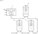
- FIG. 1 illustrates a conventional electrode slurry transfer system.
- the slurry formed in the mixer 10 is transferred to the mixer storage tank 20, the transfer tank 30, and finally to the coater supply tank 40, which supplies the slurry to the coating roll.
- the temperature of the slurry affects coating quality, loading deviations, etc. during the coating process, so controlling it to the proper level is very important to ensure consistent electrode quality.
- the temperature of the transferred slurry has a profile with periodic highs and lows.
- the time required to stabilize the slurry to the target temperature can be excessively long.
- the coating process which is a continuous process, is stopped for a while due to a changeover, disconnection, etc., and the process is resumed after adjusting the process conditions, and the temperature condition of the slurry may also be adjusted according to the adjustment of the process conditions. And depending on the readjustment of the temperature condition of the slurry, a longer waiting time for the slurry to reach the target temperature can reduce the production rate.
- the present invention seeks to provide an electrode slurry transfer system and an electrode slurry temperature control method that minimizes the time required to adjust the temperature of the electrode slurry to a target value, thereby minimizing the loss of the slurry and the current collector.
- An electrode slurry transfer system for transferring an electrode slurry from a mixer where an electrode slurry is mixed, to a coater for coating an electrode slurry, including: a mixer storage tank for storing an electrode slurry discharged from a mixer; a first transfer tank for storing a high temperature slurry and connected to the mixer storage tank by a first transfer pipe branched in parallel; a second transfer tank for storing a low temperature slurry and connected to the mixer storage tank by a first transfer pipe branched in parallel; a coater supply tank configured to receive a high temperature slurry and a low temperature slurry from the first and second transfer tanks, respectively, and to supply an electrode slurry mixture thereof to a coater; a flow rate regulating portion configured to regulate a transfer flow rate of a high temperature slurry introduced into the coater supply tank from the first transfer tank, and a transfer flow rate of a low temperature slurry introduced into the coater supply tank
- An electrode slurry transfer system may further include: a second transfer pipe connecting between the first transfer tank and the flow rate regulating portion to introduce a high temperature slurry into the flow rate regulating portion; a third transfer pipe connecting between the second transfer tank and the flow rate regulating portion to introduce a low temperature slurry into the flow rate regulating portion; a fourth transfer pipe connecting between the flow rate regulating portion and the coater supply tank to introduce high temperature and low temperature slurries into the coater supply tank; and a fifth transfer pipe connecting between the coater supply tank and the coater to introduce an electrode slurry into the coater.
- the flow rate regulating portion is provided with a first port connected to the second transfer pipe and a second port connected to the third transfer pipe, and may be configured to adjust an opening and closing rate of the first port and an opening and closing rate of the second port.
- control portion may be configured to control a temperature of an electrode slurry in a coater supply tank by adjusting an opening and closing rate of the first and second ports, respectively.
- An electrode slurry transfer system may further include a plurality of temperature sensors to measure the temperature of the electrode slurry, wherein the temperature sensor may be installed in a mixer storage tank, a first transfer tank, a second transfer tank, a coater supply tank, and a fifth transfer pipe, respectively.
- a first return pipe returning to the first transfer tank is branched from the second transfer pipe, and a first valve may be installed at the branching portion of the second transfer pipe and the first return pipe, and a second return pipe returning to the second transfer tank is branched from the third transfer pipe, and a second valve may be installed at the branching portion of the third transfer pipe and the second return pipe.
- An electrode slurry transfer system may further include: a first circulation pump installed on the first return pipe to provide a driving force to circulate a high temperature slurry to a first transfer tank; and a second circulation pump installed on the second return pipe to provide a driving force to circulate a low temperature slurry to a second transfer tank.
- An electrode slurry transfer system may further include a plurality of temperature sensors to measure the temperature of the electrode slurry, wherein the temperature sensor may be installed in a mixer storage tank, a first return pipe, a second return pipe, a coater supply tank, and a fifth transfer pipe, respectively.
- any one or more tanks among the mixer storage tank, the first transfer tank, and the second transfer tank may include: a chamber to receive a slurry; and a jacket formed on a wall of the chamber and circulating coolant to regulate the temperature of the slurry.
- control portion may be configured to control the temperature of an electrode slurry in any one or more tanks among the mixer storage tank, the first transfer tank, and the second transfer tank, by regulating the temperature of the coolant in the jacket.
- control portion may be configured to control the temperature of an electrode slurry by PID control (Proportional Integral Derivative Control).
- control portion may control so that the temperature (Th) of a high temperature slurry in the first transfer tank satisfies condition 1 below, and the temperature (Tl) of a low temperature slurry in the second transfer tank satisfies condition 2 below.
- the control portion may control so that the temperature (Th) of a high temperature slurry in the first transfer tank satisfies condition 3 below, and the temperature (Tl) of a low temperature slurry in the second transfer tank satisfies condition 4 below.
- control portion may control so that the temperature of an electrode slurry in the mixer storage tank is equal to the target temperature (Ts) of an electrode slurry in the coater supply tank.
- control portion may control the temperature of the electrode slurry such that the sensing value of the temperature sensor installed in the fifth transfer pipe is the same as the sensing value of the temperature sensor installed in the coater supply tank.
- a method of controlling the temperature of an electrode slurry according to an exemplary embodiment of the present invention uses the electrode slurry transfer system.
- the electrode slurry transfer system and the temperature control method of an electrode slurry according to the present invention wherein a first transfer tank and a second transfer tank separately store high temperature slurry and low temperature slurry, respectively, and control the temperature of the electrode slurry in a coater supply tank by mixing them, but a flow rate regulating portion regulates the flow rate of the high temperature slurry and the flow rate of the low temperature slurry introduced into the coater supply tank, respectively, so that the slurry in the coater supply tank can quickly reach the target temperature.
- the electrode slurry transfer system and the temperature control method of an electrode slurry according to the present invention when regulating the temperature of the slurry, controls the temperature of the electrode slurry in the mixer storage tank to be the same as the target temperature of the electrode slurry in the coater supply tank, so that the time required to regulate the temperature of the electrode slurry in the first transfer tank and the second transfer tank can be reduced.
- the electrode slurry transfer system and the temperature control method of the electrode slurry according to the present invention have the effect of increasing the production rate while reducing the loss of slurry and current collector consumed for temperature stabilization during coating, without requiring a major design change to the electrode slurry transfer system, since only one additional transfer tank and a flow rate regulating portion need to be installed in the conventional electrode slurry transfer system including a storage tank, a transfer tank, and a coater supply tank.
- FIG. 2 is a schematic diagram of an electrode slurry transfer system according to an exemplary embodiment of the present invention.
- arrows with a solid line indicate the flow of the slurry.
- An electrode slurry transfer system 100 includes a mixer storage tank 110, a first transfer tank 120, a second transfer tank 130, a coater supply tank 140, a flow rate regulating portion 150, and a control portion (not shown).
- electrode slurry may be prepared by mixing an electrode active material, a conductive material, and a binder or the like, and an electrode slurry prepared in the mixer may be transferred in the order of: a mixer storage tank 110, a first transfer tank 120 and a second transfer tank 130, a flow rate regulating portion 150, and a coater supply tank 140.
- An electrode slurry transferred to the coater supply tank 140 may be supplied to a coater C, coated on the current collector, and then subjected to processes such as drying, rolling, and the like.
- the mixer storage tank 110 is the primary storage tank for an electrode slurry discharged from the mixer.
- the electrode slurry in the mixer storage tank 110 is transferred in parallel to the first transfer tank 120 and the second transfer tank 130.
- the area between the mixer storage tank 110 and the first transfer tank 120 and the area between the mixer storage tank 110 and the second transfer tank 130 are each connected by a first transfer pipe 161 branched in parallel. That is, the first transfer pipe 161 has a structure in which it is branched into two pipes as shown in FIG. 2 , with one end of the first transfer pipe 161 extending into the interior of the mixer storage tank 110, and the other end of the branched transfer pipe extending into the interior of the first transfer tank 120 and the second transfer tank 130, respectively.
- a valve 193 may be installed at a branch point along the path of the first transfer pipe, wherein the valve 193 may be a 3-way valve, specifically.
- the first transfer tank 120 receives electrode slurry from the mixer storage tank 110 by the first transfer pipe 161, and stores the high temperature slurry.
- the temperature of the high temperature slurry stored in the first transfer tank 120 may be set to be higher than or equal to the target temperature Ts of the electrode slurry in the coater supply tank 140.
- the second transfer tank 130 receives electrode slurry from the mixer storage tank 110 by the first transfer pipe 161, and stores the low temperature slurry.
- the temperature of the low temperature slurry stored in the second transfer tank 130 may be set to be lower than or equal to the target temperature Ts of the electrode slurry in the coater supply tank 140.
- the coater supply tank 140 is a tank for storing electrode slurry for supplying to the coater C. It may receive high temperature slurry and low temperature slurry from the first transfer tank 120 and the second transfer tank 130, respectively, and store a mixture thereof.
- the flow rate regulating portion 150 may be configured to regulate the temperature of the introduced electrode slurry in the coater supply tank 140 by regulating a flow rate of high temperature slurry into the coater supply tank 140 from the first transfer tank 120 and a flow rate of low temperature slurry into the coater supply tank 140 from the second transfer tank 130, respectively.
- the first transfer tank 120 and the flow rate regulating portion 150 are connected by a second transfer pipe 162, and the high temperature slurry in the first transfer tank 120 flows into the flow rate regulating portion 150 by the second transfer pipe 162.
- the second transfer tank 130 and the flow rate regulating portion 150 are connected by a third transfer pipe 163, and the low temperature slurry in the second transfer tank 130 flows into the flow rate regulating portion 150 by the third transfer pipe 163.
- the flow rate regulating portion 150 and the coater supply tank 140 are connected by a fourth transfer pipe 164, which introduces high temperature slurry and low temperature slurry into the coater supply tank 140.
- the coater supply tank 140 and the coater C are connected by a fifth transfer pipe 165, and the electrode slurry in the coater supply tank 140 flows into the coater C by the fifth transfer pipe 165.
- a control portion for controlling the temperature of the electrode slurry, may be configured to control the temperature of the electrode slurry in the coater supply tank by controlling each of the mixer storage tank, the first transfer tank, the second transfer tank, and the flow rate regulating portion.
- the electrode slurry transfer system 100 divides the transfer tank, which supplies electrode slurry to a coater supply tank 140 in order to minimize the time required for the temperature of the electrode slurry in the coater supply tank 140 to reach a target temperature Ts, in two, wherein the first transfer tank 120 is configured to supply a high temperature slurry and the second transfer tank 130 is configured to supply a low temperature slurry, respectively, and the flow rate regulating portion 150 regulates the flow rate of the high temperature slurry and the flow rate of the low temperature slurry, respectively, so that the temperature of the electrode slurry in the coater supply tank 140 can be quickly controlled to reach a target temperature Ts.
- the target temperature is an arbitrarily specified value of the temperature to be targeted for the slurry temperature control.
- FIG. 3 is a schematic illustration of a flow rate regulating portion according to one embodiment of the present invention.
- the flow rate regulating portion 150 may have a first port 151, a second port 152, and a third port 153 connected to a second transfer pipe 162, a third transfer pipe 163, and a fourth transfer pipe 164, respectively. And, these first to third ports 151-153 may configure a flow rate regulating portion housing 154 of the flow rate regulating portion.
- a flow rate control valve (not shown) configured to open and close each of the first port 151 and the second port 152 may be installed, wherein one flow rate control valve may regulate the respective opening and closing rates of the first port 151 and the second port 152, or a flow rate control valve may be installed at each of the first port 151 and the second port 152 such that each flow rate control valve regulates the opening and closing rate of the first port 151 and the opening and closing rate of the second port 152.
- a respective opening and closing rate of the first port 151 and the second port 152 may be regulated by the control portion, thereby controlling the temperature of the electrode slurry in the coater supply tank 140. Specifically, if the temperature of the electrode slurry in the coater supply tank 140 needs to be increased, the first port 151 can be opened 100% to 75% and the second port 152 can be opened 0% to 25% to increase the flow rate of the high temperature slurry being introduced through the first port.
- the first port 151 can be opened 0% to 25% and the second port 152 can be opened 100% to 75% to increase the flow rate of the low temperature slurry being introduced through the second port.
- the flow rate regulating portion 150 may further include an actuator (not shown) that operates the flow rate control valve on one side of the flow rate control valve (not shown), and a flow rate control valve controller (not shown) that controls the operation of the actuator by receiving input from the control portion (not shown) of a respective opening and closing rate of the first port and the second port.
- the electrode slurry transfer system of the present invention further includes a plurality of temperature sensors for measuring the temperature of the electrode slurry in order to control the temperature of the electrode slurry, wherein the temperature sensors may be installed in the mixer storage tank 110, the first transfer tank 120, the second transfer tank 130, the coater supply tank 140, and the fifth transfer pipe 165, respectively.
- the temperature sensor may be configured to measure the temperature of the electrode slurry in real time and transmit the measured temperature data to the control portion in real time. Accordingly, the control portion may control the temperature of the electrode slurry supplied to the coater C to a target temperature in real time based on the received temperature data.
- control portion may control the temperature of the electrode slurry by means of PID control (Propotional Integral Derivative Control).
- PID control is a proportional control method that utilizes the difference between a target temperature and the current temperature, such that the temperature of the electrode slurry supplied to the coater C can be controlled to a target temperature.
- FIG. 4 is a schematic diagram of a first transfer tank according to an exemplary embodiment of the present invention.
- the first transfer tank may include a chamber 121 receiving the slurry S, an impeller 122 disposed in the interior of the chamber 121 to mix the slurry S, a temperature sensor 170 to measure the temperature of the slurry S, and a jacket 123 formed on a wall of the chamber 121 to regulate the temperature of the slurry S.
- an inlet pipe 121a and an outlet pipe 121b are formed, so that the slurry S can be introduced into and discharged from the chamber 121.
- An impeller 122 may be installed inside the chamber 121, and may be driven by an external driving force of the chamber 121 to mix the electrode slurry S inside the chamber.
- the impeller 122 may be driven by a motor provided in a central upper portion of the chamber 121.
- the jacket 123 may be formed on an outer surface of the chamber 121 and configured to circulate coolant to regulate the internal temperature of the chamber 121 and the temperature of the incoming slurry S.
- a jacket 123 spirally connected along the outer surface of the chamber 121 may form a passage between the chamber 121 and the jacket 123, and coolant may be circulated along the passage.
- a coolant inlet pipe 123a and a coolant outlet pipe 123b are connected to the jacket 123, so that coolant can be continuously introduced and discharged. Meanwhile, there is no particular restriction on the position of the jacket 123, so a configuration in which the jacket 123 is formed on the inner surface of the chamber 121 is also possible.
- the temperature sensor 170 is installed inside the chamber 121, and can measure the temperature inside the chamber 121 and the temperature of the incoming slurry S in real time.
- the temperature data measured by the temperature sensor 170 is transmitted to the control portion, and the control portion can regulate the temperature of the coolant flowing inside the jacket based on the temperature data to control the temperature of the electrode slurry stored in the first transfer tank 120 to a high temperature.
- the above configuration for the first transfer tank 120 can be adopted for the second transfer tank 130 and the mixer storage tank 110.
- the second transfer tank may include a configuration of a chamber, an impeller, a temperature sensor, and a jacket to control the temperature of the electrode slurry in the second transfer tank 130 to a low temperature
- the mixer storage tank 110 may include a configuration of a chamber, an impeller, a temperature sensor, and a jacket to control the temperature of the electrode slurry stored in the mixer storage tank 110.
- control portion may control the temperature of the electrode slurry inside the mixer storage tank 110, the first transfer tank 120, and the second transfer tank 130 to a suitable temperature range by regulating the temperature of the coolant.
- the control portion may control so that the temperature (Th) of a high temperature slurry in the first transfer tank 120 satisfies condition 1 below, and the temperature (Tl) of a low temperature slurry in the second transfer tank 130 satisfies condition 2 below.
- the control portion may control so that the temperature (Th) of a high temperature slurry in the first transfer tank satisfies condition 3 below, and the temperature (Tl) of a low temperature slurry in the second transfer tank satisfies condition 4 below.
- control portion may control a temperature of the electrode slurry in the mixer storage tank 110 to be equal to a target temperature (Ts) of the electrode slurry in the coater supply tank 140.
- Ts target temperature
- the temperature change of the slurry supplied in the first transfer tank 120 and the second transfer tank 130, respectively may be minimized, thereby reducing the stabilization time of the slurry temperature.
- the control portion can control the temperature of the electrode slurry such that the sensing value of the temperature sensor 170 installed in the fifth transfer pipe 165 is the same as the sensing value of the temperature sensor 170 installed in the coater supply tank 140. Accordingly, the electrode slurry transfer system causes the electrode slurry in the coater supply tank 140 having a changed temperature to be supplied to the coater C according to the respective flow rate control of the high temperature slurry and the low temperature slurry entering the coater supply tank 140.
- FIG. 5 is a schematic diagram of an electrode slurry transfer system according to another exemplary embodiment of the present invention.
- a first return pipe 266 returning to the first transfer tank 220 from the second transfer pipe 262 is branched, with a first valve 291 installed at the branching portion of the second transfer pipe 262 and the first return pipe 266, and a second return pipe 267 returning to the second transfer tank 230 from the third transfer pipe 263 is branched, with a second valve 292 installed at the branching portion of the third transfer pipe 263 and the second return pipe 267.
- Each of the first valve 291 and the second valve 292 may be a three-way valve.
- the electrode slurry discharged from the first transfer tank 220 is pumped by a pump (not shown) and transferred to the coater supply tank 240 via the second transfer pipe 262, but if more than a set amount of slurry is supplied in the coater supply tank 240, the slurry supply to the coater supply tank 240 can be blocked by the first valve 291, and the electrode slurry may be returned to the first transfer tank 220 via the first return pipe 266.
- the supply of slurry to the coater supply tank 240 may be blocked by the second valve 292, thereby the electrode slurry discharged from the second transfer tank 230 may be returned to the second transfer tank 230 via the second return pipe 267.
- the electrode slurry transfer system 200 may further include: a first circulation pump (not shown) installed on the first return pipe 266 to provide a driving force to circulate high temperature slurry to the first transfer tank 220; and a second circulation pump (not shown) installed on the second return pipe 267 to provide a driving force to circulate low temperature slurry to the second transfer tank 230.
- a first circulation pump (not shown) installed on the first return pipe 266 to provide a driving force to circulate high temperature slurry to the first transfer tank 220
- a second circulation pump (not shown) installed on the second return pipe 267 to provide a driving force to circulate low temperature slurry to the second transfer tank 230.
- electrode slurry transfer system 200 may further include a plurality of temperature sensors 270 for measuring the temperature of the electrode slurry, wherein the temperature sensors 270 may be installed in the mixer storage tank 210, the first return pipe 266, the second return pipe 267, the coater supply tank 240, and the fifth transfer pipe 265, respectively.
- the temperature sensor 270 may be configured to measure the temperature of the electrode slurry in real time and transmit the measurement data to the control portion, and the control portion may, based on the measurement data received from the temperature sensor, adjust the operation of the various components comprising the electrode transfer system to control the temperature of the electrode slurry so that the temperature of the electrode slurry reaches a target temperature.
- the temperature control method of the electrode slurry according to the present invention controls the temperature of the electrode slurry by utilizing the electrode slurry transfer system described above.
- a temperature control method of an electrode slurry includes a slurry supply process S 1 in which an electrode slurry prepared by a mixer not shown is supplied to a mixer storage tank 110, a first transfer tank 120 and a second transfer tank 130, and a coater supply tank 140; an electrode slurry temperature measuring process S2 of measuring the temperature of the electrode slurry, via temperature sensors installed in the mixer storage tank, the first transfer tank, the second transfer tank, the coater supply tank and the fifth transfer pipe, respectively; an electrode slurry temperature regulating process S3 of regulating the temperature of the electrode slurry in each of the mixer storage tank 110, the first transfer tank 120, and the second transfer tank 130 by an indirect method with a coolant; a process S4 of regulating a transfer flow rate of the high temperature slurry from the first transfer tank 120 to the coater supply tank 140 and a transfer flow rate of the low temperature slurry from the second transfer tank 130 to the coater supply tank 140
- the electrode slurry discharged from the mixer storage tank 110 may be introduced into the first transfer tank 120 and the second transfer tank 130 by the first transfer pipe 161 having a parallel branched structure. Accordingly, the first transfer tank 120 supplies high temperature slurry to the coater supply tank 140 via the second transfer pipe 162 and the flow rate regulating portion 150, and the second transfer tank 130 supplies low temperature slurry to the coater supply tank 140 via the third transfer pipe 163 and the flow rate regulating portion 150.
- the process of measuring the temperature of the electrode slurry S2 is a process of determining the current temperature of the electrode slurry, and the electrode slurry temperature control method according to the present invention measures the temperature of the electrode slurry in real time through the temperature sensor and transmits the temperature data to the control portion.
- the indirect method of coolant may be a heat exchange method in which indirect heating or indirect cooling is achieved by circulating the coolant inside the jacket, as previously described.
- the process S4 of regulating a transfer flow rate of the high temperature slurry entering the coater supply tank 140 from the first transfer tank 120, and a respective transfer flow rate of the low temperature slurry entering the coater supply tank 140 from the second transfer tank 130 is a process of regulating a transfer flow rate of the high temperature slurry into the coater supply tank 140, and a transfer flow rate of the low temperature slurry into the coater supply tank 140, in order to cause the temperature of the electrode slurry in the coater supply tank 140 to quickly reach a target temperature.
- the flow rate regulating portion 150 can regulate the transfer flow rate of the high temperature slurry and the transfer flow rate of the low temperature slurry entering the coater supply tank 140 by adjusting the respective opening and closing rates of the first port 151 connected with the second transfer pipe 162 and the second port 152 connected with the third transfer pipe 163.
- the process S5 of controlling the temperature of the coolant, the transfer flow rate of the high temperature slurry, and the transfer flow rate of the low temperature slurry by the flow rate regulating portion in real time may include controlling the temperature of the respective electrode slurry in the mixer storage tank 110, the first transfer tank 120, and the second transfer tank 130 by adjusting the temperature of the coolant circulating through the respective jackets installed in the mixer storage tank 110, the first transfer tank 120, and the second transfer tank 130. It may also include controlling the operation of a flow rate regulating portion to control the temperature of the electrode slurry in the coater supply tank 140 to meet a target temperature.
- the electrode slurry transfer system and the temperature control method of the electrode slurry according to the present invention wherein the first transfer tank and the second transfer tank separately store high temperature slurry and low temperature slurry, respectively, and the flow rate regulating portion regulates the flow rate of the high temperature slurry and the flow rate of the low temperature slurry entering the coater supply tank, so that the temperature of the slurry in the coater supply tank can be controlled to quickly reach a target temperature.
- the time required to reach the target value can be reduced, increasing production rates and reducing the loss amount of slurry and current collector required to stabilize the temperature during coating.
Landscapes
- Chemical & Material Sciences (AREA)
- Chemical Kinetics & Catalysis (AREA)
- Engineering & Computer Science (AREA)
- Manufacturing & Machinery (AREA)
- Electrochemistry (AREA)
- General Chemical & Material Sciences (AREA)
- Materials Engineering (AREA)
- Battery Electrode And Active Subsutance (AREA)
- Coating Apparatus (AREA)
- Processing And Handling Of Plastics And Other Materials For Molding In General (AREA)
- Treatment Of Sludge (AREA)
Abstract
Description
- This application claims the benefit of priority to
Korean Patent Application No. 10-2022-0139373, filed on Oct. 26, 2022 - The present invention relates to a transfer system for electrode slurry for transferring from a mixer to a coater that coats an electrode slurry to an electrode current collector and a method for controlling the temperature of electrode slurry.
- More specifically, the present invention relates to an electrode slurry transfer system and a method for controlling the temperature of an electrode slurry that controls the temperature of the slurry by mixing a high temperature slurry and a low temperature slurry in a power receiving method, reduces the waiting time consumed for controlling the temperature of the slurry, and reduces the loss of the slurry used for controlling the temperature.
- A secondary battery, which can be charged and discharged repeatedly, is used in various electronic devices. Meanwhile, as the types and shapes of electronic devices are diversifying, the types of secondary batteries installed in electronic devices are also diversifying. Recently, lithium-ion secondary batteries, which use lithium as a secondary battery, have been widely used.
- To manufacture these secondary batteries, a negative electrode coated with a negative electrode active material, a positive electrode coated with a positive electrode active material, and a separator placed between the negative electrode and positive electrode are required. To manufacture these negative electrode and positive electrode active materials, a mixture of electrode active materials, conductive materials, and binders, called a slurry is often required.
- Specifically, the manufacturing of positive electrode and negative electrode includes a mixing process to mix raw materials, as well as processes such as coating, drying, roll pressing, taping, and slitting. In the mixing process, where raw materials such as electrode active materials, conductive materials, and binders are mixed to form a uniform slurry, the temperature of the slurry gradually increases due to the heat of mixing, and the slurry is then transported through various tanks and coolant is used to control the temperature of the slurry to the desired temperature.
-
FIG. 1 illustrates a conventional electrode slurry transfer system. Referring toFIG. 1 , in the prior art, the slurry formed in themixer 10 is transferred to themixer storage tank 20, the transfer tank 30, and finally to thecoater supply tank 40, which supplies the slurry to the coating roll. - The temperature of the slurry affects coating quality, loading deviations, etc. during the coating process, so controlling it to the proper level is very important to ensure consistent electrode quality.
- Since electrode coating is continuous, but slurry mixing is done in batches, and the temperature of the transferred slurry has a profile with periodic highs and lows. Here, in sections where the temperature changes rapidly, the time required to stabilize the slurry to the target temperature can be excessively long. In addition, if the coating process, which is a continuous process, is stopped for a while due to a changeover, disconnection, etc., and the process is resumed after adjusting the process conditions, and the temperature condition of the slurry may also be adjusted according to the adjustment of the process conditions. And depending on the readjustment of the temperature condition of the slurry, a longer waiting time for the slurry to reach the target temperature can reduce the production rate.
- Therefore, there is a need to develop technologies that reduce the amount of current collector and slurry lost for temperature stabilization during coating and minimize the waiting time required to adjust the temperature of the slurry to the target value.
- The present invention seeks to provide an electrode slurry transfer system and an electrode slurry temperature control method that minimizes the time required to adjust the temperature of the electrode slurry to a target value, thereby minimizing the loss of the slurry and the current collector.
- An electrode slurry transfer system according to an exemplary embodiment of the present invention is an electrode slurry transfer system for transferring an electrode slurry from a mixer where an electrode slurry is mixed, to a coater for coating an electrode slurry, including: a mixer storage tank for storing an electrode slurry discharged from a mixer; a first transfer tank for storing a high temperature slurry and connected to the mixer storage tank by a first transfer pipe branched in parallel; a second transfer tank for storing a low temperature slurry and connected to the mixer storage tank by a first transfer pipe branched in parallel;a coater supply tank configured to receive a high temperature slurry and a low temperature slurry from the first and second transfer tanks, respectively, and to supply an electrode slurry mixture thereof to a coater; a flow rate regulating portion configured to regulate a transfer flow rate of a high temperature slurry introduced into the coater supply tank from the first transfer tank, and a transfer flow rate of a low temperature slurry introduced into the coater supply tank from the second transfer tank, respectively; and a control portion for controlling a temperature of the electrode slurry in the coater supply tank.
- An electrode slurry transfer system according to an exemplary embodiment of the present invention may further include: a second transfer pipe connecting between the first transfer tank and the flow rate regulating portion to introduce a high temperature slurry into the flow rate regulating portion; a third transfer pipe connecting between the second transfer tank and the flow rate regulating portion to introduce a low temperature slurry into the flow rate regulating portion; a fourth transfer pipe connecting between the flow rate regulating portion and the coater supply tank to introduce high temperature and low temperature slurries into the coater supply tank; and a fifth transfer pipe connecting between the coater supply tank and the coater to introduce an electrode slurry into the coater.
- In an electrode slurry transfer system according to an exemplary embodiment of the present invention, the flow rate regulating portion is provided with a first port connected to the second transfer pipe and a second port connected to the third transfer pipe, and may be configured to adjust an opening and closing rate of the first port and an opening and closing rate of the second port.
- In an electrode slurry transfer system according to an exemplary embodiment of the present invention, the control portion may be configured to control a temperature of an electrode slurry in a coater supply tank by adjusting an opening and closing rate of the first and second ports, respectively.
- An electrode slurry transfer system according to an exemplary embodiment of the present invention may further include a plurality of temperature sensors to measure the temperature of the electrode slurry, wherein the temperature sensor may be installed in a mixer storage tank, a first transfer tank, a second transfer tank, a coater supply tank, and a fifth transfer pipe, respectively.
- In an electrode slurry transfer system according to an exemplary embodiment of the present invention, a first return pipe returning to the first transfer tank is branched from the second transfer pipe, and a first valve may be installed at the branching portion of the second transfer pipe and the first return pipe, and a second return pipe returning to the second transfer tank is branched from the third transfer pipe, and a second valve may be installed at the branching portion of the third transfer pipe and the second return pipe.
- An electrode slurry transfer system according to an exemplary embodiment of the present invention may further include: a first circulation pump installed on the first return pipe to provide a driving force to circulate a high temperature slurry to a first transfer tank; and a second circulation pump installed on the second return pipe to provide a driving force to circulate a low temperature slurry to a second transfer tank.
- An electrode slurry transfer system according to an exemplary embodiment of the present invention may further include a plurality of temperature sensors to measure the temperature of the electrode slurry, wherein the temperature sensor may be installed in a mixer storage tank, a first return pipe, a second return pipe, a coater supply tank, and a fifth transfer pipe, respectively.
- In an electrode slurry transfer system according to an exemplary embodiment of the present invention, any one or more tanks among the mixer storage tank, the first transfer tank, and the second transfer tank may include: a chamber to receive a slurry; and a jacket formed on a wall of the chamber and circulating coolant to regulate the temperature of the slurry.
- In an electrode slurry transfer system according to an exemplary embodiment of the present invention, the control portion may be configured to control the temperature of an electrode slurry in any one or more tanks among the mixer storage tank, the first transfer tank, and the second transfer tank, by regulating the temperature of the coolant in the jacket.
- In an electrode slurry transfer system according to an exemplary embodiment of the present invention, the control portion may be configured to control the temperature of an electrode slurry by PID control (Proportional Integral Derivative Control).
- In an electrode slurry transfer system according to an exemplary embodiment of the present invention, the control portion may control so that the temperature (Th) of a high temperature slurry in the first transfer tank satisfies condition 1 below, and the temperature (Tl) of a low temperature slurry in the second transfer tank satisfies condition 2 below.


- In an electrode slurry transfer system according to an exemplary embodiment of the present invention, the control portion may control so that the temperature (Th) of a high temperature slurry in the first transfer tank satisfies condition 3 below, and the temperature (Tl) of a low temperature slurry in the second transfer tank satisfies condition 4 below.


- In an electrode slurry transfer system according to an exemplary embodiment of the present invention, the control portion may control so that the temperature of an electrode slurry in the mixer storage tank is equal to the target temperature (Ts) of an electrode slurry in the coater supply tank.
- In an electrode slurry transfer system according to an exemplary embodiment of the present invention, the control portion may control the temperature of the electrode slurry such that the sensing value of the temperature sensor installed in the fifth transfer pipe is the same as the sensing value of the temperature sensor installed in the coater supply tank.
- A method of controlling the temperature of an electrode slurry according to an exemplary embodiment of the present invention uses the electrode slurry transfer system.
- The electrode slurry transfer system and the temperature control method of an electrode slurry according to the present invention, wherein a first transfer tank and a second transfer tank separately store high temperature slurry and low temperature slurry, respectively, and control the temperature of the electrode slurry in a coater supply tank by mixing them, but a flow rate regulating portion regulates the flow rate of the high temperature slurry and the flow rate of the low temperature slurry introduced into the coater supply tank, respectively, so that the slurry in the coater supply tank can quickly reach the target temperature.
- The electrode slurry transfer system and the temperature control method of an electrode slurry according to the present invention, when regulating the temperature of the slurry, controls the temperature of the electrode slurry in the mixer storage tank to be the same as the target temperature of the electrode slurry in the coater supply tank, so that the time required to regulate the temperature of the electrode slurry in the first transfer tank and the second transfer tank can be reduced.
- In addition, the electrode slurry transfer system and the temperature control method of the electrode slurry according to the present invention have the effect of increasing the production rate while reducing the loss of slurry and current collector consumed for temperature stabilization during coating, without requiring a major design change to the electrode slurry transfer system, since only one additional transfer tank and a flow rate regulating portion need to be installed in the conventional electrode slurry transfer system including a storage tank, a transfer tank, and a coater supply tank.
-
-
FIG. 1 is a schematic diagram of a conventional electrode slurry transfer system. -
FIG. 2 is a schematic diagram of an electrode slurry transfer system according to an exemplary embodiment of the present invention. -
FIG. 3 is a schematic illustration of a flow rate regulating portion according to an exemplary embodiment of the present invention. -
FIG. 4 is a schematic illustration of a first transfer tank according to an exemplary embodiment of the present invention. -
FIG. 5 is a schematic diagram of an electrode slurry transfer system according to another exemplary embodiment of the present invention. - Hereinafter, with reference to the accompanying drawings, various embodiments of the present invention are described in detail to facilitate practice by one having ordinary skill in the art to which the invention belongs. The present invention may be implemented in many different forms and is not limited to the embodiments described herein.
- In order to clearly illustrate the present invention, parts not pertinent to the description have been omitted, and identical or similar components are designated by the same reference numerals throughout the specification.
Furthermore, the dimensions of each configuration shown in the drawings are arbitrary for purposes of illustration, and the present invention is not necessarily limited to those illustrated. - Also, throughout the specification, when a part is said to "include" a component, it means that it may further include other components, not that it excludes other components, unless specifically stated to the contrary.
-
FIG. 2 is a schematic diagram of an electrode slurry transfer system according to an exemplary embodiment of the present invention. InFIG. 2 , arrows with a solid line indicate the flow of the slurry. - An electrode
slurry transfer system 100, according to an exemplary embodiment of the present invention, includes amixer storage tank 110, afirst transfer tank 120, asecond transfer tank 130, acoater supply tank 140, a flowrate regulating portion 150, and a control portion (not shown). - In a mixer not shown, electrode slurry may be prepared by mixing an electrode active material, a conductive material, and a binder or the like, and an electrode slurry prepared in the mixer may be transferred in the order of: a
mixer storage tank 110, afirst transfer tank 120 and asecond transfer tank 130, a flowrate regulating portion 150, and acoater supply tank 140. An electrode slurry transferred to thecoater supply tank 140 may be supplied to a coater C, coated on the current collector, and then subjected to processes such as drying, rolling, and the like. - The
mixer storage tank 110 is the primary storage tank for an electrode slurry discharged from the mixer. The electrode slurry in themixer storage tank 110 is transferred in parallel to thefirst transfer tank 120 and thesecond transfer tank 130. - In order to transfer the electrode slurry discharged from the
mixer storage tank 110 to thefirst transfer tank 120 and thesecond transfer tank 130 in parallel, the area between themixer storage tank 110 and thefirst transfer tank 120 and the area between themixer storage tank 110 and thesecond transfer tank 130 are each connected by a first transfer pipe 161 branched in parallel. That is, the first transfer pipe 161 has a structure in which it is branched into two pipes as shown inFIG. 2 , with one end of the first transfer pipe 161 extending into the interior of themixer storage tank 110, and the other end of the branched transfer pipe extending into the interior of thefirst transfer tank 120 and thesecond transfer tank 130, respectively. - In one specific example, a
valve 193 may be installed at a branch point along the path of the first transfer pipe, wherein thevalve 193 may be a 3-way valve, specifically. - The
first transfer tank 120 receives electrode slurry from themixer storage tank 110 by the first transfer pipe 161, and stores the high temperature slurry. In one particular example, the temperature of the high temperature slurry stored in thefirst transfer tank 120 may be set to be higher than or equal to the target temperature Ts of the electrode slurry in thecoater supply tank 140. - The
second transfer tank 130 receives electrode slurry from themixer storage tank 110 by the first transfer pipe 161, and stores the low temperature slurry. In one particular example, the temperature of the low temperature slurry stored in thesecond transfer tank 130 may be set to be lower than or equal to the target temperature Ts of the electrode slurry in thecoater supply tank 140. - The
coater supply tank 140 is a tank for storing electrode slurry for supplying to the coater C. It may receive high temperature slurry and low temperature slurry from thefirst transfer tank 120 and thesecond transfer tank 130, respectively, and store a mixture thereof. - The flow
rate regulating portion 150 may be configured to regulate the temperature of the introduced electrode slurry in thecoater supply tank 140 by regulating a flow rate of high temperature slurry into thecoater supply tank 140 from thefirst transfer tank 120 and a flow rate of low temperature slurry into thecoater supply tank 140 from thesecond transfer tank 130, respectively. - The
first transfer tank 120 and the flowrate regulating portion 150 are connected by asecond transfer pipe 162, and the high temperature slurry in thefirst transfer tank 120 flows into the flowrate regulating portion 150 by thesecond transfer pipe 162. - The
second transfer tank 130 and the flowrate regulating portion 150 are connected by athird transfer pipe 163, and the low temperature slurry in thesecond transfer tank 130 flows into the flowrate regulating portion 150 by thethird transfer pipe 163. - The flow
rate regulating portion 150 and thecoater supply tank 140 are connected by afourth transfer pipe 164, which introduces high temperature slurry and low temperature slurry into thecoater supply tank 140. - The
coater supply tank 140 and the coater C are connected by afifth transfer pipe 165, and the electrode slurry in thecoater supply tank 140 flows into the coater C by thefifth transfer pipe 165. - A control portion (not shown), for controlling the temperature of the electrode slurry, may be configured to control the temperature of the electrode slurry in the coater supply tank by controlling each of the mixer storage tank, the first transfer tank, the second transfer tank, and the flow rate regulating portion.
- The electrode
slurry transfer system 100 according to the present invention divides the transfer tank, which supplies electrode slurry to acoater supply tank 140 in order to minimize the time required for the temperature of the electrode slurry in thecoater supply tank 140 to reach a target temperature Ts, in two, wherein thefirst transfer tank 120 is configured to supply a high temperature slurry and thesecond transfer tank 130 is configured to supply a low temperature slurry, respectively, and the flowrate regulating portion 150 regulates the flow rate of the high temperature slurry and the flow rate of the low temperature slurry, respectively, so that the temperature of the electrode slurry in thecoater supply tank 140 can be quickly controlled to reach a target temperature Ts. Here, the target temperature is an arbitrarily specified value of the temperature to be targeted for the slurry temperature control. -
FIG. 3 is a schematic illustration of a flow rate regulating portion according to one embodiment of the present invention. Referring toFIG. 3 , the flowrate regulating portion 150 may have afirst port 151, asecond port 152, and athird port 153 connected to asecond transfer pipe 162, athird transfer pipe 163, and afourth transfer pipe 164, respectively. And, these first to third ports 151-153 may configure a flow rate regulatingportion housing 154 of the flow rate regulating portion. - Inside the flow rate regulating
portion housing 154, a flow rate control valve (not shown) configured to open and close each of thefirst port 151 and thesecond port 152 may be installed, wherein one flow rate control valve may regulate the respective opening and closing rates of thefirst port 151 and thesecond port 152, or a flow rate control valve may be installed at each of thefirst port 151 and thesecond port 152 such that each flow rate control valve regulates the opening and closing rate of thefirst port 151 and the opening and closing rate of thesecond port 152. - In the flow
rate regulating portion 150, a respective opening and closing rate of thefirst port 151 and thesecond port 152 may be regulated by the control portion, thereby controlling the temperature of the electrode slurry in thecoater supply tank 140. Specifically, if the temperature of the electrode slurry in thecoater supply tank 140 needs to be increased, thefirst port 151 can be opened 100% to 75% and thesecond port 152 can be opened 0% to 25% to increase the flow rate of the high temperature slurry being introduced through the first port. Conversely, if the temperature of the electrode slurry in thecoater supply tank 140 needs to be lowered, thefirst port 151 can be opened 0% to 25% and thesecond port 152 can be opened 100% to 75% to increase the flow rate of the low temperature slurry being introduced through the second port. - The flow
rate regulating portion 150 may further include an actuator (not shown) that operates the flow rate control valve on one side of the flow rate control valve (not shown), and a flow rate control valve controller (not shown) that controls the operation of the actuator by receiving input from the control portion (not shown) of a respective opening and closing rate of the first port and the second port. - The electrode slurry transfer system of the present invention further includes a plurality of temperature sensors for measuring the temperature of the electrode slurry in order to control the temperature of the electrode slurry, wherein the temperature sensors may be installed in the
mixer storage tank 110, thefirst transfer tank 120, thesecond transfer tank 130, thecoater supply tank 140, and thefifth transfer pipe 165, respectively. - The temperature sensor may be configured to measure the temperature of the electrode slurry in real time and transmit the measured temperature data to the control portion in real time. Accordingly, the control portion may control the temperature of the electrode slurry supplied to the coater C to a target temperature in real time based on the received temperature data.
- In one specific example, the control portion may control the temperature of the electrode slurry by means of PID control (Propotional Integral Derivative Control). PID control is a proportional control method that utilizes the difference between a target temperature and the current temperature, such that the temperature of the electrode slurry supplied to the coater C can be controlled to a target temperature.
-
FIG. 4 is a schematic diagram of a first transfer tank according to an exemplary embodiment of the present invention. Referring toFIG. 4 , the first transfer tank may include achamber 121 receiving the slurry S, animpeller 122 disposed in the interior of thechamber 121 to mix the slurry S, atemperature sensor 170 to measure the temperature of the slurry S, and ajacket 123 formed on a wall of thechamber 121 to regulate the temperature of the slurry S. - In the
chamber 121, aninlet pipe 121a and anoutlet pipe 121b are formed, so that the slurry S can be introduced into and discharged from thechamber 121. Animpeller 122 may be installed inside thechamber 121, and may be driven by an external driving force of thechamber 121 to mix the electrode slurry S inside the chamber. For example, theimpeller 122 may be driven by a motor provided in a central upper portion of thechamber 121. - The
jacket 123 may be formed on an outer surface of thechamber 121 and configured to circulate coolant to regulate the internal temperature of thechamber 121 and the temperature of the incoming slurry S. For example, ajacket 123 spirally connected along the outer surface of thechamber 121 may form a passage between thechamber 121 and thejacket 123, and coolant may be circulated along the passage. In addition, acoolant inlet pipe 123a and acoolant outlet pipe 123b are connected to thejacket 123, so that coolant can be continuously introduced and discharged. Meanwhile, there is no particular restriction on the position of thejacket 123, so a configuration in which thejacket 123 is formed on the inner surface of thechamber 121 is also possible. - The
temperature sensor 170 is installed inside thechamber 121, and can measure the temperature inside thechamber 121 and the temperature of the incoming slurry S in real time. The temperature data measured by thetemperature sensor 170 is transmitted to the control portion, and the control portion can regulate the temperature of the coolant flowing inside the jacket based on the temperature data to control the temperature of the electrode slurry stored in thefirst transfer tank 120 to a high temperature. - The above configuration for the
first transfer tank 120 can be adopted for thesecond transfer tank 130 and themixer storage tank 110. That is, like the first transfer tank, the second transfer tank may include a configuration of a chamber, an impeller, a temperature sensor, and a jacket to control the temperature of the electrode slurry in thesecond transfer tank 130 to a low temperature, and themixer storage tank 110 may include a configuration of a chamber, an impeller, a temperature sensor, and a jacket to control the temperature of the electrode slurry stored in themixer storage tank 110. - In an electrode slurry transfer system of this configuration, the control portion may control the temperature of the electrode slurry inside the
mixer storage tank 110, thefirst transfer tank 120, and thesecond transfer tank 130 to a suitable temperature range by regulating the temperature of the coolant. - In the electrode slurry transfer system according to an exemplary embodiment of the present invention, the control portion may control so that the temperature (Th) of a high temperature slurry in the
first transfer tank 120 satisfies condition 1 below, and the temperature (Tl) of a low temperature slurry in thesecond transfer tank 130 satisfies condition 2 below.

- In the electrode slurry transfer system according to an exemplary embodiment of the present invention, the control portion may control so that the temperature (Th) of a high temperature slurry in the first transfer tank satisfies condition 3 below, and the temperature (Tl) of a low temperature slurry in the second transfer tank satisfies condition 4 below.


- By controlling the temperature of the high temperature slurry in the
first transfer tank 120 and the temperature of the low temperature slurry in thesecond transfer tank 130 to satisfy each of the above conditions 1 and 2, and more specifically, conditions 3 and 4, a temperature change due to mixing of the high temperature slurry and the low temperature slurry introduced into thecoater supply tank 140 can be achieved in a short time. - In the electrode slurry transfer system according to an exemplary embodiment of the present invention, the control portion may control a temperature of the electrode slurry in the
mixer storage tank 110 to be equal to a target temperature (Ts) of the electrode slurry in thecoater supply tank 140. - The greater the difference between the temperature of the electrode slurry in the
mixer storage tank 110 and the temperature of the electrode slurry in thecoater supply tank 140, the longer the time required to heat and cool the slurry in the first transfer tank and the second transfer tank, respectively. Thus, by controlling the temperature of the electrode slurry in themixer storage tank 110 to be equal to the target temperature Ts of the electrode slurry in thecoater supply tank 140, the temperature change of the slurry supplied in thefirst transfer tank 120 and thesecond transfer tank 130, respectively, may be minimized, thereby reducing the stabilization time of the slurry temperature. - In the electrode slurry transfer system according to an exemplary embodiment of the present invention, the control portion can control the temperature of the electrode slurry such that the sensing value of the
temperature sensor 170 installed in thefifth transfer pipe 165 is the same as the sensing value of thetemperature sensor 170 installed in thecoater supply tank 140. Accordingly, the electrode slurry transfer system causes the electrode slurry in thecoater supply tank 140 having a changed temperature to be supplied to the coater C according to the respective flow rate control of the high temperature slurry and the low temperature slurry entering thecoater supply tank 140. -
FIG. 5 is a schematic diagram of an electrode slurry transfer system according to another exemplary embodiment of the present invention. Referring toFIG. 5 , in the electrodeslurry transfer system 200, afirst return pipe 266 returning to thefirst transfer tank 220 from thesecond transfer pipe 262 is branched, with afirst valve 291 installed at the branching portion of thesecond transfer pipe 262 and thefirst return pipe 266, and a second return pipe 267 returning to thesecond transfer tank 230 from thethird transfer pipe 263 is branched, with asecond valve 292 installed at the branching portion of thethird transfer pipe 263 and the second return pipe 267. Each of thefirst valve 291 and thesecond valve 292 may be a three-way valve. - The electrode slurry discharged from the
first transfer tank 220 is pumped by a pump (not shown) and transferred to thecoater supply tank 240 via thesecond transfer pipe 262, but if more than a set amount of slurry is supplied in thecoater supply tank 240, the slurry supply to thecoater supply tank 240 can be blocked by thefirst valve 291, and the electrode slurry may be returned to thefirst transfer tank 220 via thefirst return pipe 266. - Similarly, the supply of slurry to the
coater supply tank 240 may be blocked by thesecond valve 292, thereby the electrode slurry discharged from thesecond transfer tank 230 may be returned to thesecond transfer tank 230 via the second return pipe 267. - In addition, the electrode
slurry transfer system 200 may further include: a first circulation pump (not shown) installed on thefirst return pipe 266 to provide a driving force to circulate high temperature slurry to thefirst transfer tank 220; and a second circulation pump (not shown) installed on the second return pipe 267 to provide a driving force to circulate low temperature slurry to thesecond transfer tank 230. - In addition, electrode
slurry transfer system 200 may further include a plurality oftemperature sensors 270 for measuring the temperature of the electrode slurry, wherein thetemperature sensors 270 may be installed in themixer storage tank 210, thefirst return pipe 266, the second return pipe 267, thecoater supply tank 240, and thefifth transfer pipe 265, respectively. - The
temperature sensor 270 may be configured to measure the temperature of the electrode slurry in real time and transmit the measurement data to the control portion, and the control portion may, based on the measurement data received from the temperature sensor, adjust the operation of the various components comprising the electrode transfer system to control the temperature of the electrode slurry so that the temperature of the electrode slurry reaches a target temperature. - Hereinafter, a temperature control method of an electrode slurry according to an exemplary embodiment of the present invention will be described. The temperature control method of the electrode slurry according to the present invention controls the temperature of the electrode slurry by utilizing the electrode slurry transfer system described above.
- Referring to
FIGS. 1 to 4 , a temperature control method of an electrode slurry according to an exemplary embodiment of the present invention includes a slurry supply process S 1 in which an electrode slurry prepared by a mixer not shown is supplied to a mixer storage tank 110, a first transfer tank 120 and a second transfer tank 130, and a coater supply tank 140; an electrode slurry temperature measuring process S2 of measuring the temperature of the electrode slurry, via temperature sensors installed in the mixer storage tank, the first transfer tank, the second transfer tank, the coater supply tank and the fifth transfer pipe, respectively; an electrode slurry temperature regulating process S3 of regulating the temperature of the electrode slurry in each of the mixer storage tank 110, the first transfer tank 120, and the second transfer tank 130 by an indirect method with a coolant; a process S4 of regulating a transfer flow rate of the high temperature slurry from the first transfer tank 120 to the coater supply tank 140 and a transfer flow rate of the low temperature slurry from the second transfer tank 130 to the coater supply tank 140, respectively, by a flow rate regulating portion 150; and a process S5 of controlling a temperature of the coolant, a transfer flow rate of the high temperature slurry, and a transfer flow rate of the low temperature slurry by the flow rate regulating portion in real time. - In the slurry supply process S1, the electrode slurry discharged from the
mixer storage tank 110 may be introduced into thefirst transfer tank 120 and thesecond transfer tank 130 by the first transfer pipe 161 having a parallel branched structure. Accordingly, thefirst transfer tank 120 supplies high temperature slurry to thecoater supply tank 140 via thesecond transfer pipe 162 and the flowrate regulating portion 150, and thesecond transfer tank 130 supplies low temperature slurry to thecoater supply tank 140 via thethird transfer pipe 163 and the flowrate regulating portion 150. - The process of measuring the temperature of the electrode slurry S2 is a process of determining the current temperature of the electrode slurry, and the electrode slurry temperature control method according to the present invention measures the temperature of the electrode slurry in real time through the temperature sensor and transmits the temperature data to the control portion.
- In the process S3 of adjusting the temperature of the electrode slurry in each of the
mixer storage tank 110, thefirst transfer tank 120, and thesecond transfer tank 130, the indirect method of coolant may be a heat exchange method in which indirect heating or indirect cooling is achieved by circulating the coolant inside the jacket, as previously described. - The process S4 of regulating a transfer flow rate of the high temperature slurry entering the
coater supply tank 140 from thefirst transfer tank 120, and a respective transfer flow rate of the low temperature slurry entering thecoater supply tank 140 from thesecond transfer tank 130 is a process of regulating a transfer flow rate of the high temperature slurry into thecoater supply tank 140, and a transfer flow rate of the low temperature slurry into thecoater supply tank 140, in order to cause the temperature of the electrode slurry in thecoater supply tank 140 to quickly reach a target temperature. - At this time, the flow
rate regulating portion 150 can regulate the transfer flow rate of the high temperature slurry and the transfer flow rate of the low temperature slurry entering thecoater supply tank 140 by adjusting the respective opening and closing rates of thefirst port 151 connected with thesecond transfer pipe 162 and thesecond port 152 connected with thethird transfer pipe 163. - Based on the difference between the current temperature of the electrode slurry measured in real time in the temperature measurement process S2 by the
temperature sensor 170 and the target temperature, the process S5 of controlling the temperature of the coolant, the transfer flow rate of the high temperature slurry, and the transfer flow rate of the low temperature slurry by the flow rate regulating portion in real time may include controlling the temperature of the respective electrode slurry in themixer storage tank 110, thefirst transfer tank 120, and thesecond transfer tank 130 by adjusting the temperature of the coolant circulating through the respective jackets installed in themixer storage tank 110, thefirst transfer tank 120, and thesecond transfer tank 130. It may also include controlling the operation of a flow rate regulating portion to control the temperature of the electrode slurry in thecoater supply tank 140 to meet a target temperature. - As described above, the electrode slurry transfer system and the temperature control method of the electrode slurry according to the present invention, wherein the first transfer tank and the second transfer tank separately store high temperature slurry and low temperature slurry, respectively, and the flow rate regulating portion regulates the flow rate of the high temperature slurry and the flow rate of the low temperature slurry entering the coater supply tank, so that the temperature of the slurry in the coater supply tank can be controlled to quickly reach a target temperature.
- In addition, when adjusting the temperature of the slurry, the time required to reach the target value can be reduced, increasing production rates and reducing the loss amount of slurry and current collector required to stabilize the temperature during coating.
- The present invention has been described in more detail above with reference to the drawings and embodiments. However, it is to be understood that the configurations shown in the drawings or embodiments described herein are only one embodiment of the invention and do not represent all of the technical ideas of the present invention, and that there may be various equivalents and modifications that may replace them at the time of filing the present disclosure.
-
- 100, 200: ELECTRODE SLURRY TRANSFER SYSTEM
- 110, 210: STORAGE TANK
- 120, 220: FIRST TRANSFER TANK
- 130, 230: SECOND TRANSFER TANK
- 140, 240: COATER SUPPLY TANK
- 150, 250: FLOW RATE REGULATING PORTION
- 151-153: FIRST PORT TO THIRD PORT
- 161-165, 261-265: FIRST TRANSFER PIPE TO FIFTH TRANSFER PIPE
- 266-267: FIRST RETURN PIPE TO SECOND RETURN PIPE
- 170, 270: TEMPERATURE SENSOR
- 291 TO 293: FIRST VALVE TO THIRD VALVE
- C: COATER
Claims (16)
- An electrode slurry transfer system for transferring an electrode slurry from a mixer where an electrode slurry is mixed, to a coater for coating an electrode slurry, comprising:a mixer storage tank for storing an electrode slurry discharged from the mixer;a first transfer tank for storing a high temperature slurry and connected to the mixer storage tank by a first transfer pipe branched in parallel;a second transfer tank for storing a low temperature slurry and connected to the mixer storage tank by the first transfer pipe branched in parallel;a coater supply tank configured to receive the high temperature slurry and the low temperature slurry from the first and second transfer tanks, respectively, and to supply an electrode slurry mixture thereof to the coater;a flow rate regulating portion configured to regulate a transfer flow rate of the high temperature slurry introduced into the coater supply tank from the first transfer tank, and a transfer flow rate of the low temperature slurry introduced into the coater supply tank from the second transfer tank, respectively; anda control portion for controlling a temperature of the electrode slurry in the coater supply tank.
- The electrode slurry transfer system of claim 1, further comprisinga second transfer pipe connecting between the first transfer tank and the flow rate regulating portion to introduce the high temperature slurry into the flow rate regulating portion;a third transfer pipe connecting between the second transfer tank and the flow rate regulating portion to introduce the low temperature slurry into the flow rate regulating portion;a fourth transfer pipe connecting between the flow rate regulating portion and the coater supply tank to introduce high temperature and low temperature slurries into the coater supply tank; anda fifth transfer pipe connecting between the coater supply tank and the coater to introduce the electrode slurry into the coater.
- The electrode slurry transfer system of claim 2, whereinthe flow rate regulating portion is provided witha first port connected to the second transfer pipe and a second port connected to the third transfer pipe, andis configured to adjust an opening and closing rate of the first port and an opening and closing rate of the second port.
- The electrode slurry transfer system of claim 3, wherein
the control portion controls a temperature of an electrode slurry in the coater supply tank by adjusting an opening and closing rate of the first and second ports, respectively. - The electrode slurry transfer system of claim 2, further comprising a plurality of temperature sensors to measure the temperature of the electrode slurry, wherein
the temperature sensor is installed in the mixer storage tank, the first transfer tank, the second transfer tank, the coater supply tank, and the fifth transfer pipe, respectively. - The electrode slurry transfer system of claim 2, whereina first return pipe returning to the first transfer tank is branched from the second transfer pipe, and a first valve is installed at the branching portion of the second transfer pipe and the first return pipe, anda second return pipe returning to the second transfer tank is branched from the third transfer pipe, and a second valve is installed at the branching portion of the third transfer pipe and the second return pipe.
- The electrode slurry transfer system of claim 6, further comprisinga first circulation pump installed on the first return pipe to provide a driving force to circulate the high temperature slurry to the first transfer tank; anda second circulation pump installed on the second return pipe to provide a driving force to circulate the low temperature slurry to the second transfer tank.
- The electrode slurry transfer system of claim 6, further comprisinga plurality of temperature sensors to measure the temperature of the electrode slurry, whereinthe temperature sensor is installed in the mixer storage tank, the first return pipe, the second return pipe, the coater supply tank, and the fifth transfer pipe, respectively.
- The electrode slurry transfer system of claim 1, wherein
any one or more tanks among the mixer storage tank, the first transfer tank, and the second transfer tank comprises:a chamber to receive a slurry; anda jacket formed on a wall of the chamber and circulating coolant to regulate the temperature of the slurry. - The electrode slurry transfer system of claim 9, wherein
the control portion is configured to control the temperature of an electrode slurry in any one or more tanks among the mixer storage tank, the first transfer tank, and the second transfer tank, by regulating the temperature of the coolant in the jacket. - The electrode slurry transfer system of claim 1, wherein
the control portion is configured to control the temperature of the electrode slurry by Proportional Integral Derivative PID control. - The electrode slurry transfer system of claim 1, whereinthe control portion controls so thatthe temperature Th of the high temperature slurry in the first transfer tank satisfies condition 1 below, andthe temperature Tl of the low temperature slurry in the second transfer tank satisfies condition 2 below;(In Condition 1 and Condition 2 above, Ts is the target temperature of the electrode slurry in the coater supply tank).


- The electrode slurry transfer system of claim 1, whereinthe control portion controls so thatthe temperature Th of the high temperature slurry in the first transfer tank satisfies condition 3 below, andthe temperature Tl of the low temperature slurry in the second transfer tank satisfies condition 4 below;In Condition 3 and Condition 4 above, Ts is the target temperature of the electrode slurry in the coater supply tank.
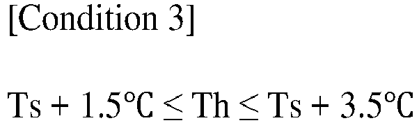

- The electrode slurry transfer system of claim 1, wherein
the control portion controls so that the temperature of the electrode slurry in the mixer storage tank is equal to the target temperature Ts of the electrode slurry in the coater supply tank. - The electrode slurry transfer system of claim 2, wherein
the control portion controls the temperature of the electrode slurry such that the sensing value of the temperature sensor installed in the fifth transfer pipe is the same as the sensing value of the temperature sensor installed in the coater supply tank. - A method of controlling the temperature of an electrode slurry using an electrode slurry transfer system according to any one of claims 1 to 15.
Applications Claiming Priority (2)
| Application Number | Priority Date | Filing Date | Title |
|---|---|---|---|
| KR1020220139373A KR20240058537A (en) | 2022-10-26 | 2022-10-26 | Transfer system for electrode slurry and temperature control method for electrode slurry using same |
| PCT/KR2023/016735 WO2024091016A1 (en) | 2022-10-26 | 2023-10-26 | Electrode slurry transfer system and electrode slurry temperature control method using same |
Publications (2)
| Publication Number | Publication Date |
|---|---|
| EP4459688A1 true EP4459688A1 (en) | 2024-11-06 |
| EP4459688A4 EP4459688A4 (en) | 2025-07-30 |
Family
ID=90831386
Family Applications (1)
| Application Number | Title | Priority Date | Filing Date |
|---|---|---|---|
| EP23883121.8A Pending EP4459688A4 (en) | 2022-10-26 | 2023-10-26 | Electrode slurry transfer system and electrode slurry temperature control method using same |
Country Status (6)
| Country | Link |
|---|---|
| US (1) | US20250100007A1 (en) |
| EP (1) | EP4459688A4 (en) |
| JP (1) | JP2025502443A (en) |
| KR (1) | KR20240058537A (en) |
| CN (1) | CN118872085A (en) |
| WO (1) | WO2024091016A1 (en) |
Families Citing this family (1)
| Publication number | Priority date | Publication date | Assignee | Title |
|---|---|---|---|---|
| KR102884603B1 (en) * | 2023-05-16 | 2025-11-12 | 주식회사 윤성에프앤씨 | Mixer supporter with coolant line |
Family Cites Families (9)
| Publication number | Priority date | Publication date | Assignee | Title |
|---|---|---|---|---|
| JPH0798139B2 (en) * | 1988-04-28 | 1995-10-25 | 積水化学工業株式会社 | Mixing ratio controller |
| JP3374540B2 (en) * | 1994-07-22 | 2003-02-04 | トヨタ車体株式会社 | Paint supply device |
| JP2004047347A (en) * | 2002-07-15 | 2004-02-12 | Shin Kobe Electric Mach Co Ltd | Method for producing paste-like active material for positive electrode and lead storage battery using the same |
| KR101613318B1 (en) * | 2008-08-11 | 2016-04-18 | 프라이믹스 가부시키가이샤 | Method and device for producing a coating material |
| KR102073188B1 (en) * | 2013-06-21 | 2020-02-04 | 삼성에스디아이 주식회사 | Coating apparatus of active material for battery and using method thereof |
| US12185360B2 (en) | 2020-02-13 | 2024-12-31 | Nokia Solutions And Networks Oy | Processing rules for resource elements |
| KR102937918B1 (en) | 2020-10-19 | 2026-03-10 | 주식회사 엘지에너지솔루션 | Temperature control method for slurry |
| KR102877573B1 (en) * | 2020-10-19 | 2025-10-27 | 주식회사 엘지에너지솔루션 | Slurry temperature simulation device and slurry temperature simulation method using the same |
| KR102953618B1 (en) * | 2020-12-17 | 2026-04-15 | 주식회사 엘지에너지솔루션 | System for conveying electrode slurry |
-
2022
- 2022-10-26 KR KR1020220139373A patent/KR20240058537A/en active Pending
-
2023
- 2023-10-26 CN CN202380021016.8A patent/CN118872085A/en active Pending
- 2023-10-26 US US18/832,277 patent/US20250100007A1/en active Pending
- 2023-10-26 WO PCT/KR2023/016735 patent/WO2024091016A1/en not_active Ceased
- 2023-10-26 EP EP23883121.8A patent/EP4459688A4/en active Pending
- 2023-10-26 JP JP2024543245A patent/JP2025502443A/en active Pending
Also Published As
| Publication number | Publication date |
|---|---|
| EP4459688A4 (en) | 2025-07-30 |
| CN118872085A (en) | 2024-10-29 |
| WO2024091016A1 (en) | 2024-05-02 |
| US20250100007A1 (en) | 2025-03-27 |
| KR20240058537A (en) | 2024-05-03 |
| JP2025502443A (en) | 2025-01-24 |
Similar Documents
| Publication | Publication Date | Title |
|---|---|---|
| EP4459688A1 (en) | Electrode slurry transfer system and electrode slurry temperature control method using same | |
| CN215141565U (en) | Slurry feeding device | |
| US20240399410A1 (en) | Slurry Supply Device and Slurry Supply Method | |
| EP3327829B1 (en) | Battery electrode slurry distribution method, and battery electrode slurry processing method | |
| US10692748B2 (en) | High-tech temperature control device for semiconductor manufacturing facility | |
| CN204719557U (en) | A kind of cooling control system of temperature control device | |
| CN115176353B (en) | Electrode manufacturing system with excellent electrode slurry coating uniformity and electrode manufacturing method using the same | |
| US20240083218A1 (en) | Control system for thermal management and distribution | |
| CN100368191C (en) | Method for constant temperature and regulating device for constant temperature | |
| CN107051356B (en) | Temperature control system, temperature control method and control terminal for powder coating physical polymerization tank | |
| CN218223251U (en) | Slurry conveying device and slurry coating equipment | |
| KR102937918B1 (en) | Temperature control method for slurry | |
| CN115388448A (en) | Automatic control method and system for cooling and heating system | |
| CN118491787A (en) | High-temperature coating system and battery production system | |
| CN220346367U (en) | Coating system | |
| KR20230031395A (en) | Electrode slurry coating device for secondary battery and electrode slurry coating method using the same | |
| KR102877573B1 (en) | Slurry temperature simulation device and slurry temperature simulation method using the same | |
| CN214682676U (en) | Coating device | |
| CN217160292U (en) | Liquid cooling system capable of simultaneously adjusting liquid supply pressure, flow and liquid supply temperature | |
| CN118281435A (en) | Battery cooling system, power battery for vehicle and cooling control method thereof | |
| CN113769994B (en) | Coating machine | |
| CN121198556A (en) | A lithium battery coating and feeding device and method | |
| CN210741236U (en) | Temperature control device | |
| CN223240165U (en) | Palladium plating device for wafer | |
| KR20110022075A (en) | Temperature control method and fuel cell system in fuel cell system |
Legal Events
| Date | Code | Title | Description |
|---|---|---|---|
| STAA | Information on the status of an ep patent application or granted ep patent |
Free format text: STATUS: THE INTERNATIONAL PUBLICATION HAS BEEN MADE |
|
| PUAI | Public reference made under article 153(3) epc to a published international application that has entered the european phase |
Free format text: ORIGINAL CODE: 0009012 |
|
| STAA | Information on the status of an ep patent application or granted ep patent |
Free format text: STATUS: REQUEST FOR EXAMINATION WAS MADE |
|
| 17P | Request for examination filed |
Effective date: 20240729 |
|
| AK | Designated contracting states |
Kind code of ref document: A1 Designated state(s): AL AT BE BG CH CY CZ DE DK EE ES FI FR GB GR HR HU IE IS IT LI LT LU LV MC ME MK MT NL NO PL PT RO RS SE SI SK SM TR |
|
| REG | Reference to a national code |
Ref country code: DE Ref legal event code: R079 Free format text: PREVIOUS MAIN CLASS: H01M0004040000 Ipc: B05C0011100000 |
|
| A4 | Supplementary search report drawn up and despatched |
Effective date: 20250627 |
|
| RIC1 | Information provided on ipc code assigned before grant |
Ipc: B05C 11/10 20060101AFI20250623BHEP Ipc: H01M 4/04 20060101ALI20250623BHEP Ipc: B01F 27/91 20220101ALI20250623BHEP Ipc: B01F 35/50 20220101ALI20250623BHEP Ipc: B01F 35/221 20220101ALI20250623BHEP Ipc: B01F 35/71 20220101ALI20250623BHEP Ipc: B05C 11/11 20060101ALI20250623BHEP Ipc: B05C 5/02 20060101ALN20250623BHEP |
|
| DAV | Request for validation of the european patent (deleted) | ||
| DAX | Request for extension of the european patent (deleted) | ||
| RIC1 | Information provided on ipc code assigned before grant |
Ipc: B05C 11/10 20060101AFI20260119BHEP Ipc: H01M 4/04 20060101ALI20260119BHEP Ipc: B01F 27/91 20220101ALI20260119BHEP Ipc: B01F 35/50 20220101ALI20260119BHEP Ipc: B01F 35/221 20220101ALI20260119BHEP Ipc: B01F 35/71 20220101ALI20260119BHEP Ipc: B05C 11/11 20060101ALI20260119BHEP Ipc: B05C 5/02 20060101ALN20260119BHEP |
|
| RIC1 | Information provided on ipc code assigned before grant |
Ipc: B05C 11/10 20060101AFI20260312BHEP Ipc: H01M 4/04 20060101ALI20260312BHEP Ipc: B01F 27/91 20220101ALI20260312BHEP Ipc: B01F 35/50 20220101ALI20260312BHEP Ipc: B01F 35/221 20220101ALI20260312BHEP Ipc: B01F 35/71 20220101ALI20260312BHEP Ipc: B05C 11/11 20060101ALI20260312BHEP Ipc: B05C 5/02 20060101ALN20260312BHEP |
|
| GRAP | Despatch of communication of intention to grant a patent |
Free format text: ORIGINAL CODE: EPIDOSNIGR1 |
|
| STAA | Information on the status of an ep patent application or granted ep patent |
Free format text: STATUS: GRANT OF PATENT IS INTENDED |