EP4459300A1 - Method for estimating soc of battery, and related apparatus - Google Patents
Method for estimating soc of battery, and related apparatus Download PDFInfo
- Publication number
- EP4459300A1 EP4459300A1 EP22914383.9A EP22914383A EP4459300A1 EP 4459300 A1 EP4459300 A1 EP 4459300A1 EP 22914383 A EP22914383 A EP 22914383A EP 4459300 A1 EP4459300 A1 EP 4459300A1
- Authority
- EP
- European Patent Office
- Prior art keywords
- battery
- maximum available
- available capacity
- soc
- current
- Prior art date
- Legal status (The legal status is an assumption and is not a legal conclusion. Google has not performed a legal analysis and makes no representation as to the accuracy of the status listed.)
- Granted
Links
Images

Classifications
-
- G—PHYSICS
- G01—MEASURING; TESTING
- G01R—MEASURING ELECTRIC VARIABLES; MEASURING MAGNETIC VARIABLES
- G01R31/00—Arrangements for testing electric properties; Arrangements for locating electric faults; Arrangements for electrical testing characterised by what is being tested not provided for elsewhere
- G01R31/36—Arrangements for testing, measuring or monitoring the electrical condition of accumulators or electric batteries, e.g. capacity or state of charge [SoC]
- G01R31/385—Arrangements for measuring battery or accumulator variables
- G01R31/387—Determining ampere-hour charge capacity or SoC
-
- G—PHYSICS
- G01—MEASURING; TESTING
- G01R—MEASURING ELECTRIC VARIABLES; MEASURING MAGNETIC VARIABLES
- G01R31/00—Arrangements for testing electric properties; Arrangements for locating electric faults; Arrangements for electrical testing characterised by what is being tested not provided for elsewhere
- G01R31/36—Arrangements for testing, measuring or monitoring the electrical condition of accumulators or electric batteries, e.g. capacity or state of charge [SoC]
- G01R31/382—Arrangements for monitoring battery or accumulator variables, e.g. SoC
- G01R31/3828—Arrangements for monitoring battery or accumulator variables, e.g. SoC using current integration
- G01R31/3832—Arrangements for monitoring battery or accumulator variables, e.g. SoC using current integration without measurement of battery voltage
-
- G—PHYSICS
- G01—MEASURING; TESTING
- G01R—MEASURING ELECTRIC VARIABLES; MEASURING MAGNETIC VARIABLES
- G01R31/00—Arrangements for testing electric properties; Arrangements for locating electric faults; Arrangements for electrical testing characterised by what is being tested not provided for elsewhere
- G01R31/36—Arrangements for testing, measuring or monitoring the electrical condition of accumulators or electric batteries, e.g. capacity or state of charge [SoC]
- G01R31/367—Software therefor, e.g. for battery testing using modelling or look-up tables
-
- Y—GENERAL TAGGING OF NEW TECHNOLOGICAL DEVELOPMENTS; GENERAL TAGGING OF CROSS-SECTIONAL TECHNOLOGIES SPANNING OVER SEVERAL SECTIONS OF THE IPC; TECHNICAL SUBJECTS COVERED BY FORMER USPC CROSS-REFERENCE ART COLLECTIONS [XRACs] AND DIGESTS
- Y02—TECHNOLOGIES OR APPLICATIONS FOR MITIGATION OR ADAPTATION AGAINST CLIMATE CHANGE
- Y02T—CLIMATE CHANGE MITIGATION TECHNOLOGIES RELATED TO TRANSPORTATION
- Y02T10/00—Road transport of goods or passengers
- Y02T10/60—Other road transportation technologies with climate change mitigation effect
- Y02T10/70—Energy storage systems for electromobility, e.g. batteries
Definitions
- the present application relates to the field of battery technologies, and more particularly, to a method for estimating an SOC of a battery, and a related apparatus.
- a state of charge (SOC) of a battery is a very important battery parameter.
- the SOC represents a percentage of the remaining charge capacity of a battery pack to a battery capacity, and is used for evaluating the current remaining available capacity of the battery pack. Accurate estimation of the SOC may ensure a relevant strategy for the whole vehicle, the safety of the battery, and the experience feelings of drivers and passengers.
- an ampere-hour integral algorithm is the main algorithm in a dynamic process of the battery.
- a capacity value obtained from a capacity-temperature table is used as the available capacity value of the battery to perform ampere-hour integral calculation according to the current temperature of the battery pack.
- the capacity-temperature table is inaccurate, a queried available capacity value is inaccurate, and the accuracy of the SOC is influenced accordingly.
- the present application provides a method for estimating an SOC of a battery, and a related apparatus, which aim at solving a problem that the estimation of the SOC of the battery is inaccurate.
- a method for estimating an SOC of a battery includes steps of:
- the step of obtaining the maximum available capacity corresponding to the at least one complete charging and discharging period of the battery before the current moment includes: obtaining the maximum available capacities corresponding to first N complete charging and discharging periods of the battery closest to the current moment, where, N ⁇ 1 and N is an integer.
- the step of calculating the historical maximum available capacity of the battery according to the maximum available capacities corresponding to the various complete charging and discharging period includes: performing an average calculation on the maximum available capacities corresponding to the various complete charging and discharging periods to obtain the historical maximum available capacity of the battery.
- the step of obtaining the current maximum available capacity of the battery includes:
- the method further includes: obtaining an updated current maximum available capacity by multiplying the current maximum available capacity with a health degree of the battery at the current moment.
- the step of taking the target capacity as the available capacity of the battery at the current moment, and performing the ampere-hour integral calculation to obtain the estimation value of the SOC of the battery at the current moment comprises:
- an apparatus for estimating an SOC of a battery includes:
- the historical maximum available capacity calculation module includes: a maximum available capacity obtaining unit configured to obtain the maximum available capacity corresponding to first N complete charging and discharging periods of the battery closest to the current moment, wherein, N ⁇ 1 and N is an integer.
- the historical maximum available capacity calculation module further includes: a historical maximum available capacity calculation unit configured to perform an average calculation on the maximum available capacities corresponding to the various complete charging and discharging periods to obtain the historical maximum available capacity of the battery.
- the target capacity determination module includes a current maximum available capacity obtaining unit which is configured to:
- the current maximum available capacity obtaining unit is further configured to: obtain an updated current maximum available capacity by multiplying the current maximum available capacity with a health degree of the battery at the current moment.
- the SOC estimation value obtaining module is specifically configured to:
- an electronic device in the present application.
- the electronic device includes a memory, a processor and a computer program stored in the memory and executable by the processor.
- the processor is configured to, when executing the computer program, implement the steps of any method for estimating the SOC of the battery in the first aspect.
- a computer-readable storage medium stores a computer program, characterized in that, the computer program is configured to, when executed by a processor, implement steps of any method for estimating the SOC of the battery in the first aspect.
- a vehicle in the embodiments of the present application, the vehicle includes the electronic device described in the third aspect.
- the maximum available capacity corresponding to at least one complete charging and discharging period of the battery before the current moment is obtained, and the historical maximum available capacity of the battery is calculated according to the maximum available capacities corresponding to various complete charging and discharging periods.
- the current maximum available capacity of the battery is obtained, and the difference value between the historical maximum available capacity and the current maximum available capacity is obtained, the historical maximum available capacity is taken as the target capacity if the difference value is greater than the preset difference value threshold, otherwise, the current maximum available capacity is taken as the target capacity.
- the target capacity is taken as an available capacity of the battery at the current moment, and the ampere-hour integral calculation is performed to obtain the estimation value of the SOC of the battery at the current moment.
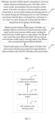
- FIG. 1 is a flowchart illustrating an implementation of a method for estimating a state of charge (SOC) of a battery according to one embodiment of the present application.
- SOC state of charge
- a maximum available capacity corresponding to at least one complete charging and discharging period of the battery before a current moment is obtained, and a historical maximum available capacity of the battery is calculated according to the maximum available capacities corresponding to various complete charging and discharging periods.
- the complete charging and discharging period is an entire discharging period during which the battery is discharged from a fully charged battery to a zero charge or an entire charging period during which the battery is charged from the zero charge to the full charge.
- An execution subject (the electronic device) of this embodiment may be a battery management system (Battery Management System).
- the complete charging and discharging period refers to an entire period during which the battery is dropped from a fully charged state until the battery is in a disabled state and has zero charge, or an entire period during which the battery starts to be charged when it is in the disabled state with zero charge until the battery is fully charged.
- the maximum available capacity corresponding to the complete charging and discharging period indicates recording the accumulated ampere-hour value in the discharging process starting from the full-power state of the battery, until the battery is in the disabled state and has zero charge, and recording the accumulated ampere-hour value at this moment as the maximum available capacity in the complete charging and discharging period.
- a specific implementation process of the step S 101 includes: the maximum available capacity corresponding to the first N complete charging and discharging periods closest to the current moment of the battery is obtained, where N ⁇ 1 and N is an integer.
- the maximum available capacities of the first N complete charging and discharging periods closest to the current moment are selected to calculate the historical maximum available capacity.
- the specific implementation process of the step S101 further includes: the maximum available capacities corresponding to various complete charging and discharging periods are averaged to obtain the historical maximum available capacity of the battery.
- Q d represents the maximum available capacity of the battery
- Q T-1 represents the maximum available capacity corresponding to the first complete charging and discharging period closest to the current moment
- Q T-2 represents the maximum available capacity corresponding to the second complete charging and discharging period closest to the current moment
- Q T-N represents the maximum available capacity corresponding to the first N-th complete charging and discharging period closest to the current moment
- a, b, ..., n represent weights of Q T-1 , Q T-2 , ⁇ , Q T-N , respectively.
- the historical maximum available capacity calculated through the abovementioned formula approximates the real value at the current moment, thereby improving the accuracy of the historical maximum available capacity.
- N may be 10.
- a step of S 102 the current maximum available capacity of the battery is obtained; and a difference value between the historical maximum available capacity and the current maximum available capacity is calculated. If the difference value is greater than a preset difference threshold, the historical maximum available capacity is taken as the target capacity; if the difference value is not greater than the preset difference threshold, the current maximum available capacity is taken as the target capacity.
- an electronic device obtains the maximum available capacity (the current maximum available capacity) of the battery at the current moment through a table lookup method.
- the difference value between the historical maximum available capacity and the current maximum available capacity obtained by the table lookup method is greater, the calculated historical maximum available capacity is more reliable, and the current maximum available capacity obtained by the table lookup method is corrected using the historical maximum available capacity. If the difference value is small, that is, the difference value is not greater than the preset difference threshold, the current maximum available capacity is not corrected, and the current maximum available capacity obtained by the table lookup method is directly used as the target capacity
- the step S 102 specifically includes:
- the specific implementation process of the step S 102 further includes: the current maximum available capacity is multiplied by a health degree of the battery at the current moment to obtain an updated current maximum available capacity.
- the preset capacity-temperature table is a table including capacities, temperatures, and correspondence relationships therebetween. Since the actual situation is usually not completely consistent with the experimental scene before delivery, the maximum available capacity obtained based on table lookup sometimes has a certain error.
- the health degree is the health state of the battery, and indicates the ratio of the actual maximum available capacity to the rated capacity of the new battery in a certain operating environment.
- the target capacity is taken as the available capacity of the battery at the current moment, and ampere-hour integral calculation is performed to obtain the estimation value of the SOC of the battery at the current moment.
- an ampere-hour integral algorithm is used to calculate the remaining available capacity of the battery in a dynamic process
- the advantage of the ampere-hour integral algorithm is that the battery has relatively smaller limitation on the ampere-hour integral algorithm, this calculation method is simple and reliable, and the SOC of the battery can be estimated in real time.
- SOCt represents the estimation value of the SOC of the battery at the moment t
- SOC t-1 represents the estimation value of the SOC of the battery at the moment t-1
- i represents the current value of the battery at the moment t
- C o represents the available capacity of the battery at the moment T.
- a method for estimating the SOC of the battery is provided in the embodiments of the present application.
- the current value of the battery at the current moment is obtained.
- the maximum available capacity corresponding to at least one complete charging and discharging period of the battery before the current moment is obtained, and the historical maximum available capacity of the battery is calculated according to the maximum available capacities corresponding to various complete charging and discharging periods.
- the current maximum available capacity of the battery is obtained, and the difference value between the historical maximum available capacity and the current maximum available capacity is obtained, the historical maximum available capacity is taken as the target capacity if the difference value is greater than the preset difference value threshold, otherwise, the current maximum available capacity is taken as the target capacity.
- the target capacity is taken as an available capacity of the battery at the current moment, and the ampere-hour integral calculation is performed to obtain the estimation value of the SOC of the battery at the current moment.
- the current maximum available capacity of the battery which is determined using the existing technologies has lower accuracy
- historical data is used to calculate the historical maximum available capacity
- the difference value between the historical maximum available capacity and the current maximum available capacity obtained by table lookup is used to determine the target capacity.
- the accuracy of calculation of the SOC is improved.
- FIG. 2 illustrates a schematic structural diagram of an apparatus for estimating an SOC of a battery provided in one embodiment of the present application.
- FIG. 2 illustrates a schematic structural diagram of an apparatus for estimating an SOC of a battery provided in one embodiment of the present application.
- the part which is relevant to the embodiments of the present application is merely illustrated.
- the apparatus is described in detail below.
- An apparatus for estimating an SOC of a battery includes:
- the historical maximum available capacity calculation module 110 includes: a maximum available capacity obtaining unit configured to obtain the maximum available capacity corresponding to the first N complete charging and discharging periods of the battery closest to the current moment, where N ⁇ 1 and N is an integer.
- the historical maximum available capacity calculation module 110 further includes: a historical maximum available capacity calculation unit configured to perform an average calculation on the maximum available capacities corresponding to the various complete charging and discharging periods to obtain the historical maximum available capacity of the battery.
- the target capacity determination module includes a current maximum available capacity obtaining unit configured to:
- the current maximum available capacity obtaining unit is further configured to: obtain an updated current maximum available capacity by multiplying the current maximum available capacity with a health degree of the battery at the current moment.
- the SOC estimation value obtaining module 130 is specifically configured to:
- the estimation value of the SOC may be calculated by considering multidimensional factors such as a historical maximum available capacity value, a capacity-temperature table, and the battery health degree (SOH) in the charging and discharging operation process of the battery, and the problem that the introduction of SOC error, which is caused due to improper capacity selection, enables the estimation of the SOC to be inaccurate and thereby influencing the accuracy of the SOC is avoided.
- multidimensional factors such as a historical maximum available capacity value, a capacity-temperature table, and the battery health degree (SOH) in the charging and discharging operation process of the battery
- a computer program product is further provided in the embodiments of the present application.
- the computer program product has program codes, that, when executed on a corresponding processor, a controller, a computing device, or an electronic device, performs the steps in any one of the method embodiments for estimating the SOC of the battery, such as the steps S101 to S103 shown in FIG. 1 .
- a person of ordinary skill in the art should understand that the method and the apparatus proposed in the embodiments of the present application may be implemented in various forms of hardware, software, firmware, an application specific processor, or a combination thereof.
- the application specific processor may include an application specific integrated circuit (ASIC), a reduced instruction set computer (RISC), and/or a field programmable gate array (FPGA).
- ASIC application specific integrated circuit
- RISC reduced instruction set computer
- FPGA field programmable gate array
- the proposed method and apparatus are preferably implemented as a combination of hardware and software.
- the software is preferably an application program installed on a program storage device, which is typically a machine based on a computer platform with hardware, such as one or a plurality of central processing units (CPUs), random access memory (RAM), and one or a plurality of input/output (I/O) interfaces.
- An operating system is also installed on the computer platform typically.
- the various processes and functions described herein may be a part of the application program, or alternatively, a part of the various processes and functions may be executed by the operating system.
- FIG. 3 is a schematic diagram of an electronic device according to one embodiment of the present application.
- the electronic device 3 in this embodiment includes: a processor 30, a memory 31, and a computer program 32 stored in the memory 31 and executable by the processor 30.
- the processor 30 is configured to, when executing the computer program 32, implement the steps (e.g., the steps 101 to 103 shown in FIG. 1 ) in the various method embodiments for estimating the SOC of the battery.
- the processor 30 is configure to, when executing the computer program 32, implement the functions (e.g., the functions of the module 110, the module 120 and the module 130 shown in FIG. 2 ) of the various modules/units in the apparatus embodiments.
- the computer program 32 may be divided into one or a plurality of modules/units, the one or plurality of modules/units are stored in the memory 31, and executed by the processor 30 so as to accomplish/implement the technical solutions proposed in the present application.
- the one or plurality of modules/units may be a series of computer program instruction segments that can accomplish particular functionalities, these instruction segments are used for describing an executive process of the computer program 32 in the electronic device 3.
- the computer program 32 may be divided into the module 110, the module 120 and the module 130 shown in FIG. 2 .
- the electronic device 3 may include but is not limited to the processor 30, the memory 31.
- FIG. 3 is only one example of the electronic device 3, and thus should not be constituted as limitation to the electronic device 3. More or less components than the components shown in FIG. 3 may be included, as an alternative, some components or different components may be combined,
- the electronic device 3 may also include an input and output device, a network access device, a bus, etc.
- the so-called processor 30 may be central processing unit (CPU), and can also be other general purpose processor, digital signal processor (DSP), application specific integrated circuit (ASIC), field-programmable gate array (FGPA), or some other programmable logic devices, discrete gate or transistor logic device, discrete hardware component, etc.
- the general purpose processor may be a microprocessor, as an alternative, the processor may also be any conventional processor, or the like.
- the memory 31 may be an internal storage unit of the electronic device 3, such as a hard disk or a memory of the electronic device 3.
- the memory 31 may also be an external storage device of the electronic device 3, such as a plug-in hard disk, a smart media card (Smart Media Card, SMC), a secure digital (Secure Digital, SD) card, a flash card (Flash Card, FC) equipped on the electronic device 3.
- the memory 31 may not only include the internal storage unit of the electronic device 3, but also include the external memory of the electronic device 3.
- the memory 31 is configured to store the computer program, and other procedures and data as required by the electronic device 3.
- the memory 31 may also be configured to store data that has been output or being ready to be output temporarily.
- a vehicle is further provided in this embodiment.
- the vehicle includes the aforementioned electronic device.
- the disclosed device/electronic device and method could be implemented in other ways.
- the aforementioned apparatus/electronic device embodiments are merely illustrative.
- the division of the units is only a logical function division, and other division could be used in the actual implementation.
- multiple units or components could be combined or integrated into another system, or some features may be ignored, or not performed.
- the coupling or direct coupling or communicating connection shown or discussed could be an indirect coupling or a communicating connection through some interfaces, devices or units, and the coupling or direct coupling or communicating connection could be electrical, mechanical, or in other form.
- the units described as separate components can be or cannot be physically separate, the components shown as units can be or cannot be physical units, the components may be located in one place, or be distributed onto multiple network elements. A part or a whole of the elements can be selected to achieve the objective of the technical solution of this embodiment according to the actual requirement.
- each of the embodiments of the present application may be integrated into a single processing unit, or exist individually and physically, or two or more than two units are integrated into a single unit.
- the aforesaid integrated unit can either be achieved by hardware, or be achieved in the form of software functional units.
- the integrated unit When the integrated unit is achieved in the form of software functional units, and is sold or used as an independent product, the integrated unit may be stored in a computer readable storage medium. Based on this understanding, a whole or part of flow process for implementing the method in the embodiments of the present application can also be accomplished in the manner of using computer program to instruct relevant hardware. When the computer program is executed by the processor, the steps in the various method embodiments described above may be implemented.
- the computer program comprises computer program codes, which may be in the form of source code, object code, executable documents or some intermediate form, etc.
- the computer readable medium can include: any physical equipment or device that can carry the computer program codes, recording medium, USB flash disk, mobile hard disk, hard disk, optical disk, computer memory, ROM (Read-Only Memory), RAM (Random Access Memory), electrical carrier signal, telecommunication signal and software distribution medium, etc. It needs to be explained that, the contents contained in the computer readable medium may be added or reduced appropriately according to the requirement of legislation and patent practice in a judicial district, for example, in some judicial districts, according to legislation and patent practice, the computer readable medium doesn't include electrical carrier signal and telecommunication signal.
Landscapes
- Physics & Mathematics (AREA)
- General Physics & Mathematics (AREA)
- Secondary Cells (AREA)
- Charge And Discharge Circuits For Batteries Or The Like (AREA)
Abstract
Description
- This application claims priority to Chinese patent application No.
CN202111627071.0 filed on December 28, 2021 - The present application relates to the field of battery technologies, and more particularly, to a method for estimating an SOC of a battery, and a related apparatus.
- In a battery management system, a state of charge (SOC) of a battery is a very important battery parameter. The SOC represents a percentage of the remaining charge capacity of a battery pack to a battery capacity, and is used for evaluating the current remaining available capacity of the battery pack. Accurate estimation of the SOC may ensure a relevant strategy for the whole vehicle, the safety of the battery, and the experience feelings of drivers and passengers.
- When performing an estimation on the SOC, an ampere-hour integral algorithm is the main algorithm in a dynamic process of the battery. In the related art, a capacity value obtained from a capacity-temperature table is used as the available capacity value of the battery to perform ampere-hour integral calculation according to the current temperature of the battery pack. However, if the capacity-temperature table is inaccurate, a queried available capacity value is inaccurate, and the accuracy of the SOC is influenced accordingly.
- The present application provides a method for estimating an SOC of a battery, and a related apparatus, which aim at solving a problem that the estimation of the SOC of the battery is inaccurate.
- In accordance with the first aspect, a method for estimating an SOC of a battery is provided in the present application. The method includes steps of:
- obtaining a maximum available capacity corresponding to at least one complete charging and discharging period of the battery before a current moment, and calculating a historical maximum available capacity of the battery according to maximum available capacities corresponding to various complete charging and discharging periods; the complete charging and discharging period is an entire discharging period during which the battery is discharged from a full charge to a zero charge or an entire charging period during which the battery is charged from the zero charge to the full charge;
- obtaining a current maximum available capacity of the battery and calculating a difference value between the historical maximum available capacity and the current maximum available capacity, and taking the historical maximum available capacity as a target capacity if the difference value is greater than a preset difference threshold; or alternatively, taking the current maximum available capacity as the target capacity if the difference value is not greater than the preset difference threshold; and
- taking the target capacity as an available capacity of the battery at the current moment, and performing an ampere-hour integral calculation to obtain an estimation value of the SOC of the battery at the current moment.
- In one possible implementation manner, the step of obtaining the maximum available capacity corresponding to the at least one complete charging and discharging period of the battery before the current moment includes:
obtaining the maximum available capacities corresponding to first N complete charging and discharging periods of the battery closest to the current moment, where, N≥1 and N is an integer. - In one possible implementation manner, the step of calculating the historical maximum available capacity of the battery according to the maximum available capacities corresponding to the various complete charging and discharging period includes:
performing an average calculation on the maximum available capacities corresponding to the various complete charging and discharging periods to obtain the historical maximum available capacity of the battery. - In one possible implementation manner, the step of obtaining the current maximum available capacity of the battery includes:
- acquiring a current temperature of the battery;
- querying the current maximum available capacity corresponding to the battery at the current temperature according to a preset capacity-temperature table.
- In one possible implementation manner, after the step of querying the current maximum available capacity corresponding to the battery at the current temperature according to the preset capacity-temperature table, the method further includes:
obtaining an updated current maximum available capacity by multiplying the current maximum available capacity with a health degree of the battery at the current moment. - In one possible implementation manner, the step of taking the target capacity as the available capacity of the battery at the current moment, and performing the ampere-hour integral calculation to obtain the estimation value of the SOC of the battery at the current moment comprises:
- obtaining the estimation value of the SOC of the battery at the current moment through a formula expressed as:

- where, SOCt represents the estimation value of the SOC at a moment t, SOCt-1 represents the estimation value of the SOC at a moment t-1, i represents a current value of the battery at the moment t, and Co represents an available capacity of the battery at the moment t.
- In accordance with the second aspect, an apparatus for estimating an SOC of a battery is provided. The apparatus includes:
- a historical maximum available capacity calculation module configured to obtain a maximum available capacity corresponding to at least one complete charging and discharging period of the battery before a current moment, and calculate a historical maximum available capacity of the battery according to maximum available capacities corresponding to various complete charging and discharging periods; the complete charging and discharging period is an entire discharging period during which the battery is discharged from a full charge to a zero charge or an entire charging period during which the battery is charged from the zero charge to the full charge;
- a target capacity determination module configured to obtain a current maximum available capacity of the battery and calculate a difference value between the historical maximum available capacity and the current maximum available capacity, and take the historical maximum available capacity as a target capacity if the difference value is greater than a preset difference threshold, or take the current maximum available capacity as the target capacity if the difference value is not greater than the preset difference threshold; and
- an SOC estimation value obtaining module configured to take the target capacity as an available capacity of the battery at the current moment, and perform an ampere-hour integral calculation to obtain an estimation value of the SOC of the battery at the current moment.
- In one possible implementation manner, the historical maximum available capacity calculation module includes:
a maximum available capacity obtaining unit configured to obtain the maximum available capacity corresponding to first N complete charging and discharging periods of the battery closest to the current moment, wherein, N≥1 and N is an integer. - In one possible implementation manner, the historical maximum available capacity calculation module further includes:
a historical maximum available capacity calculation unit configured to perform an average calculation on the maximum available capacities corresponding to the various complete charging and discharging periods to obtain the historical maximum available capacity of the battery. - In one possible implementation manner, the target capacity determination module includes a current maximum available capacity obtaining unit which is configured to:
- obtain a current temperature of the battery;
- query a corresponding current maximum available capacity of the battery at the current temperature according to a preset capacity-temperature table.
- In one possible implementation manner, the current maximum available capacity obtaining unit is further configured to:
obtain an updated current maximum available capacity by multiplying the current maximum available capacity with a health degree of the battery at the current moment. - In one possible implementation manner, the SOC estimation value obtaining module is specifically configured to:
- obtain the estimation value of the SOC of the battery at the current moment through a formula expressed as:

- where, SOCt represents the estimation value of the SOC at a moment t, SOCt-1 represents the estimation value of the SOC at a moment t-1, i represents a current value of the battery at the moment t, and Co represents an available capacity of the battery at the moment t.
- In accordance with the third aspect, an electronic device is provided in the present application. The electronic device includes a memory, a processor and a computer program stored in the memory and executable by the processor. The processor is configured to, when executing the computer program, implement the steps of any method for estimating the SOC of the battery in the first aspect.
- In accordance with the fourth aspect, a computer-readable storage medium is provided in the embodiments of the present application. The computer-readable storage medium stores a computer program, characterized in that, the computer program is configured to, when executed by a processor, implement steps of any method for estimating the SOC of the battery in the first aspect.
- In accordance with the fifth aspect, a vehicle is provided in the embodiments of the present application, the vehicle includes the electronic device described in the third aspect.
- In accordance with the method for estimating the SOC of the battery provided in the embodiments of the present application, first, the maximum available capacity corresponding to at least one complete charging and discharging period of the battery before the current moment is obtained, and the historical maximum available capacity of the battery is calculated according to the maximum available capacities corresponding to various complete charging and discharging periods. Then, the current maximum available capacity of the battery is obtained, and the difference value between the historical maximum available capacity and the current maximum available capacity is obtained, the historical maximum available capacity is taken as the target capacity if the difference value is greater than the preset difference value threshold, otherwise, the current maximum available capacity is taken as the target capacity. Finally, the target capacity is taken as an available capacity of the battery at the current moment, and the ampere-hour integral calculation is performed to obtain the estimation value of the SOC of the battery at the current moment. According to the aforementioned solutions, in this embodiment, when the current maximum available capacity of the battery which is determined using the existing technologies has lower accuracy, historical data is used to calculate the historical maximum available capacity, and the difference value between the historical maximum available capacity and the current maximum available capacity obtained by table lookup is used to determine the target capacity. Thus, the accuracy of calculation of the SOC is improved.
- In order to describe the embodiments of the present application more clearly, a brief introduction regarding the accompanying drawings that need to be used for describing the embodiments of the present application or the existing technologies is given below. It is obvious that the accompanying drawings described below are merely some embodiments of the present application, a person of ordinary skill in the art may also obtain other drawings according to the current drawings without paying creative work.
-
FIG. 1 is a flowchart illustrating an implementation of a method for estimating an SOC of a battery provided by one embodiment of the present application; -
FIG. 2 is a schematic structural diagram of an apparatus for estimating an SOC of a battery provided by one embodiment of the present application; -
FIG. 3 is a schematic diagram of an electronic device provided by one embodiment of the present application. - In the following descriptions, in order to describe but not intended to limit the present application, concrete details including specific system structure and technique are proposed to facilitate a comprehensive understanding of the embodiments of the present application. However, a person of ordinarily skill in the art should understand that, the present application may also be implemented in some other embodiments from which these concrete details are excluded. In other conditions, detailed explanations of method, circuit, device and system well known to the public are omitted, and thus unnecessary details which disturb the description of the present application are avoided.
- In order to make the objective, the technical solutions, and the advantages of the present application be clearer, the present application is described below with reference to the embodiments, and in combination with the accompanying drawings.
- Referring to
FIG. 1, FIG. 1 is a flowchart illustrating an implementation of a method for estimating a state of charge (SOC) of a battery according to one embodiment of the present application. - In a step of S 101, a maximum available capacity corresponding to at least one complete charging and discharging period of the battery before a current moment is obtained, and a historical maximum available capacity of the battery is calculated according to the maximum available capacities corresponding to various complete charging and discharging periods. The complete charging and discharging period is an entire discharging period during which the battery is discharged from a fully charged battery to a zero charge or an entire charging period during which the battery is charged from the zero charge to the full charge.
- An execution subject (the electronic device) of this embodiment may be a battery management system (Battery Management System).
- In this embodiment, the complete charging and discharging period refers to an entire period during which the battery is dropped from a fully charged state until the battery is in a disabled state and has zero charge, or an entire period during which the battery starts to be charged when it is in the disabled state with zero charge until the battery is fully charged. Taking the discharging period as an example, the maximum available capacity corresponding to the complete charging and discharging period indicates recording the accumulated ampere-hour value in the discharging process starting from the full-power state of the battery, until the battery is in the disabled state and has zero charge, and recording the accumulated ampere-hour value at this moment as the maximum available capacity in the complete charging and discharging period.
- In a possible implementation manner, a specific implementation process of the step S 101 includes:
the maximum available capacity corresponding to the first N complete charging and discharging periods closest to the current moment of the battery is obtained, where N≥1 and N is an integer. - In this embodiment, in order to improve the accuracy of the historical maximum available capacity, in this embodiment, the maximum available capacities of the first N complete charging and discharging periods closest to the current moment are selected to calculate the historical maximum available capacity.
- In one possible implementation manner, the specific implementation process of the step S101 further includes:
the maximum available capacities corresponding to various complete charging and discharging periods are averaged to obtain the historical maximum available capacity of the battery. - Furthermore, in order to improve the accuracy of the historical maximum available capacity of the battery, in this embodiment, a formula may be used to calculate the historical maximum available capacity of the battery, this formula is expressed as:

- The historical maximum available capacity calculated through the abovementioned formula approximates the real value at the current moment, thereby improving the accuracy of the historical maximum available capacity.
- For example, N may be 10.
- In a step of
S 102, the current maximum available capacity of the battery is obtained; and a difference value between the historical maximum available capacity and the current maximum available capacity is calculated. If the difference value is greater than a preset difference threshold, the historical maximum available capacity is taken as the target capacity; if the difference value is not greater than the preset difference threshold, the current maximum available capacity is taken as the target capacity. - In this embodiment, an electronic device obtains the maximum available capacity (the current maximum available capacity) of the battery at the current moment through a table lookup method. When the difference value between the historical maximum available capacity and the current maximum available capacity obtained by the table lookup method is greater, the calculated historical maximum available capacity is more reliable, and the current maximum available capacity obtained by the table lookup method is corrected using the historical maximum available capacity. If the difference value is small, that is, the difference value is not greater than the preset difference threshold, the current maximum available capacity is not corrected, and the current maximum available capacity obtained by the table lookup method is directly used as the target capacity
- In one possible implementation manner, the step S 102 specifically includes:
- in a step of S201, a current temperature of a battery is obtained;
- in a step of S202, the current maximum available capacity corresponding to the battery at the current temperature is obtained by looking up a preset capacity-temperature table.
- In one possible implementation manner, after the step S202, the specific implementation process of the
step S 102 further includes:
the current maximum available capacity is multiplied by a health degree of the battery at the current moment to obtain an updated current maximum available capacity. - In this embodiment, the preset capacity-temperature table is a table including capacities, temperatures, and correspondence relationships therebetween. Since the actual situation is usually not completely consistent with the experimental scene before delivery, the maximum available capacity obtained based on table lookup sometimes has a certain error.
- In this embodiment, the health degree is the health state of the battery, and indicates the ratio of the actual maximum available capacity to the rated capacity of the new battery in a certain operating environment.
- In a step of S 103, the target capacity is taken as the available capacity of the battery at the current moment, and ampere-hour integral calculation is performed to obtain the estimation value of the SOC of the battery at the current moment.
- In this embodiment, an ampere-hour integral algorithm is used to calculate the remaining available capacity of the battery in a dynamic process, the advantage of the ampere-hour integral algorithm is that the battery has relatively smaller limitation on the ampere-hour integral algorithm, this calculation method is simple and reliable, and the SOC of the battery can be estimated in real time.
- Specifically, the formula of the ampere-hour integral algorithm for calculating the remaining available capacity may be expressed as:

- After the remaining available capacity at the current moment is obtained through calculation, the estimation value of the SOC of the battery at the current moment is obtained according to the formula expressed as

- In one embodiment, the specific implementation process of the step S 103 may further include:
the estimation value of the SOC of the battery at the current moment is obtained through a formula expressed as
- Where, SOCt represents the estimation value of the SOC of the battery at the moment t, SOCt-1 represents the estimation value of the SOC of the battery at the moment t-1, i represents the current value of the battery at the moment t, and Co represents the available capacity of the battery at the moment T.
- It can be seen from the aforementioned embodiments that, a method for estimating the SOC of the battery is provided in the embodiments of the present application. First, the current value of the battery at the current moment is obtained. Then, the maximum available capacity corresponding to at least one complete charging and discharging period of the battery before the current moment is obtained, and the historical maximum available capacity of the battery is calculated according to the maximum available capacities corresponding to various complete charging and discharging periods. Then, the current maximum available capacity of the battery is obtained, and the difference value between the historical maximum available capacity and the current maximum available capacity is obtained, the historical maximum available capacity is taken as the target capacity if the difference value is greater than the preset difference value threshold, otherwise, the current maximum available capacity is taken as the target capacity. Finally, the target capacity is taken as an available capacity of the battery at the current moment, and the ampere-hour integral calculation is performed to obtain the estimation value of the SOC of the battery at the current moment. In this embodiment, when the current maximum available capacity of the battery which is determined using the existing technologies has lower accuracy, historical data is used to calculate the historical maximum available capacity, and the difference value between the historical maximum available capacity and the current maximum available capacity obtained by table lookup is used to determine the target capacity. Thus, the accuracy of calculation of the SOC is improved.
- It should be understood that, the values of serial numbers of the steps in the aforesaid embodiments do not indicate an order of execution sequences of the steps; instead, the execution sequences of the steps should be determined by functionalities and internal logic of the steps, and thus shouldn't be regarded as limitation to implementation processes of the embodiments of the present application.
- An apparatus embodiment of the present application is described below. Regarding the details that are not described in detail, reference can be made to the corresponding method embodiments described above.
-
FIG. 2 illustrates a schematic structural diagram of an apparatus for estimating an SOC of a battery provided in one embodiment of the present application. For the convenience of illustration, the part which is relevant to the embodiments of the present application is merely illustrated. The apparatus is described in detail below. - An apparatus for estimating an SOC of a battery, includes:
- a historical maximum available
capacity calculation module 110 configured to obtain a maximum available capacity corresponding to at least one complete charging and discharging period of the battery before a current moment, and calculate a historical maximum available capacity of the battery according to maximum available capacities corresponding to various complete charging and discharging periods; the complete charging and discharging period is an entire discharging period during which the battery is discharged from a full charge to a zero charge or an entire charging period during which the battery is charged from the zero charge to the full charge; - a target
capacity determination module 120 configured to obtain a current maximum available capacity of the battery and calculate a difference value between the historical maximum available capacity and the current maximum available capacity, and take the historical maximum available capacity as a target capacity if the difference value is greater than a preset difference threshold, or take the current maximum available capacity as the target capacity if the difference value is not greater than the preset difference threshold; - an SOC estimation
value obtaining module 130 configured to take the target capacity as an available capacity of the battery at the current moment, and perform an ampere-hour integral calculation to obtain an estimation value of the SOC of the battery at the current moment. - In one possible implementation manner, the historical maximum available
capacity calculation module 110 includes:
a maximum available capacity obtaining unit configured to obtain the maximum available capacity corresponding to the first N complete charging and discharging periods of the battery closest to the current moment, where N≥1 and N is an integer. - In one possible implementation manner, the historical maximum available
capacity calculation module 110 further includes:
a historical maximum available capacity calculation unit configured to perform an average calculation on the maximum available capacities corresponding to the various complete charging and discharging periods to obtain the historical maximum available capacity of the battery. - In one possible implementation manner, the target capacity determination module includes a current maximum available capacity obtaining unit configured to:
- obtain a current temperature of the battery;
- query a corresponding current maximum available capacity of the battery at the current temperature according to a preset capacity-temperature table.
- In one possible implementation manner, the current maximum available capacity obtaining unit is further configured to:
obtain an updated current maximum available capacity by multiplying the current maximum available capacity with a health degree of the battery at the current moment. - In one possible implementation manner, the SOC estimation
value obtaining module 130 is specifically configured to: - obtain the estimation value of the SOC of the battery at the current moment through a formula expressed as:

- where, SOCt represents the estimation value of the SOC at a moment t, SOCt-1 represents the estimation value of the SOC at a moment t-1, i represents a current value of the battery at the moment t, and Co represents the available capacity of the battery at the moment t.
- It can be seen from the aforementioned embodiment that, in this embodiment, the estimation value of the SOC may be calculated by considering multidimensional factors such as a historical maximum available capacity value, a capacity-temperature table, and the battery health degree (SOH) in the charging and discharging operation process of the battery, and the problem that the introduction of SOC error, which is caused due to improper capacity selection, enables the estimation of the SOC to be inaccurate and thereby influencing the accuracy of the SOC is avoided.
- A computer program product is further provided in the embodiments of the present application. The computer program product has program codes, that, when executed on a corresponding processor, a controller, a computing device, or an electronic device, performs the steps in any one of the method embodiments for estimating the SOC of the battery, such as the steps S101 to S103 shown in
FIG. 1 . A person of ordinary skill in the art should understand that the method and the apparatus proposed in the embodiments of the present application may be implemented in various forms of hardware, software, firmware, an application specific processor, or a combination thereof. The application specific processor may include an application specific integrated circuit (ASIC), a reduced instruction set computer (RISC), and/or a field programmable gate array (FPGA). The proposed method and apparatus are preferably implemented as a combination of hardware and software. The software is preferably an application program installed on a program storage device, which is typically a machine based on a computer platform with hardware, such as one or a plurality of central processing units (CPUs), random access memory (RAM), and one or a plurality of input/output (I/O) interfaces. An operating system is also installed on the computer platform typically. The various processes and functions described herein may be a part of the application program, or alternatively, a part of the various processes and functions may be executed by the operating system. -
FIG. 3 is a schematic diagram of an electronic device according to one embodiment of the present application. As shown inFIG. 3 , theelectronic device 3 in this embodiment includes: aprocessor 30, amemory 31, and acomputer program 32 stored in thememory 31 and executable by theprocessor 30. Theprocessor 30 is configured to, when executing thecomputer program 32, implement the steps (e.g., the steps 101 to 103 shown inFIG. 1 ) in the various method embodiments for estimating the SOC of the battery. As an alternative, theprocessor 30 is configure to, when executing thecomputer program 32, implement the functions (e.g., the functions of themodule 110, themodule 120 and themodule 130 shown inFIG. 2 ) of the various modules/units in the apparatus embodiments. - Exemplarily, the
computer program 32 may be divided into one or a plurality of modules/units, the one or plurality of modules/units are stored in thememory 31, and executed by theprocessor 30 so as to accomplish/implement the technical solutions proposed in the present application. The one or plurality of modules/units may be a series of computer program instruction segments that can accomplish particular functionalities, these instruction segments are used for describing an executive process of thecomputer program 32 in theelectronic device 3. For example, thecomputer program 32 may be divided into themodule 110, themodule 120 and themodule 130 shown inFIG. 2 . - The
electronic device 3 may include but is not limited to theprocessor 30, thememory 31. The person of ordinary skill in the art may understand that,FIG. 3 is only one example of theelectronic device 3, and thus should not be constituted as limitation to theelectronic device 3. More or less components than the components shown inFIG. 3 may be included, as an alternative, some components or different components may be combined, For example, theelectronic device 3 may also include an input and output device, a network access device, a bus, etc. - The so-called
processor 30 may be central processing unit (CPU), and can also be other general purpose processor, digital signal processor (DSP), application specific integrated circuit (ASIC), field-programmable gate array (FGPA), or some other programmable logic devices, discrete gate or transistor logic device, discrete hardware component, etc. The general purpose processor may be a microprocessor, as an alternative, the processor may also be any conventional processor, or the like. - The
memory 31 may be an internal storage unit of theelectronic device 3, such as a hard disk or a memory of theelectronic device 3. Thememory 31 may also be an external storage device of theelectronic device 3, such as a plug-in hard disk, a smart media card (Smart Media Card, SMC), a secure digital (Secure Digital, SD) card, a flash card (Flash Card, FC) equipped on theelectronic device 3. Furthermore, thememory 31 may not only include the internal storage unit of theelectronic device 3, but also include the external memory of theelectronic device 3. Thememory 31 is configured to store the computer program, and other procedures and data as required by theelectronic device 3. Thememory 31 may also be configured to store data that has been output or being ready to be output temporarily. - A vehicle is further provided in this embodiment. The vehicle includes the aforementioned electronic device.
- The person of ordinary skill in the art may clearly understand that, for the convenience of description and for conciseness, the dividing of the various functional units and functional modules is merely described according to examples. In an actual application, these functions may be assigned to different functional units and functional modules to be accomplished, that is, an inner structure of the device is divided into different functional units or modules to accomplish the whole or some of functionalities described above. The various functional units and modules in the embodiments may be integrated into a processing unit, or each of the units exists independently and physically, or two or more than two of the units are integrated into a single unit. The aforementioned integrated unit may either by actualized in the form of hardware or in the form of software functional units. In addition, specific names of the various functional units and modules are only used to be distinguished from each other conveniently, rather than being intended to limit the protection scope of the present application. Regarding the specific operating process of the units and modules in the aforementioned system, reference may be made to a corresponding process in the aforementioned method embodiments. This specific operating process of the units and modules is not repeatedly described herein.
- In the aforesaid embodiments, the descriptions of the various embodiments are emphasized respectively, regarding a part of one embodiment which has not been described or disclosed in detail, reference can be made to relevant descriptions in other embodiments.
- The person of ordinary skill in the art may understand that, the elements and algorithm steps of each of the examples described in connection with the embodiments disclosed herein may be implemented in electronic hardware, or in combination with computer software and electronic hardware. Whether these functions are implemented by hardware or software depends on the specific application and design constraints of the technical solution. The skilled people could use different methods to implement the described functions for each particular application, however, such implementations should not be considered as going beyond the scope of the present application.
- It should be understood that, in the embodiments of the present application, the disclosed device/electronic device and method could be implemented in other ways. For example, the aforementioned apparatus/electronic device embodiments are merely illustrative. For example, the division of the units is only a logical function division, and other division could be used in the actual implementation. For example, multiple units or components could be combined or integrated into another system, or some features may be ignored, or not performed. In another aspect, the coupling or direct coupling or communicating connection shown or discussed could be an indirect coupling or a communicating connection through some interfaces, devices or units, and the coupling or direct coupling or communicating connection could be electrical, mechanical, or in other form.
- The units described as separate components can be or cannot be physically separate, the components shown as units can be or cannot be physical units, the components may be located in one place, or be distributed onto multiple network elements. A part or a whole of the elements can be selected to achieve the objective of the technical solution of this embodiment according to the actual requirement.
- In addition, the various functional units in each of the embodiments of the present application may be integrated into a single processing unit, or exist individually and physically, or two or more than two units are integrated into a single unit. The aforesaid integrated unit can either be achieved by hardware, or be achieved in the form of software functional units.
- When the integrated unit is achieved in the form of software functional units, and is sold or used as an independent product, the integrated unit may be stored in a computer readable storage medium. Based on this understanding, a whole or part of flow process for implementing the method in the embodiments of the present application can also be accomplished in the manner of using computer program to instruct relevant hardware. When the computer program is executed by the processor, the steps in the various method embodiments described above may be implemented. Wherein, the computer program comprises computer program codes, which may be in the form of source code, object code, executable documents or some intermediate form, etc. The computer readable medium can include: any physical equipment or device that can carry the computer program codes, recording medium, USB flash disk, mobile hard disk, hard disk, optical disk, computer memory, ROM (Read-Only Memory), RAM (Random Access Memory), electrical carrier signal, telecommunication signal and software distribution medium, etc. It needs to be explained that, the contents contained in the computer readable medium may be added or reduced appropriately according to the requirement of legislation and patent practice in a judicial district, for example, in some judicial districts, according to legislation and patent practice, the computer readable medium doesn't include electrical carrier signal and telecommunication signal.
- In addition, the embodiments shown in the drawings of the present application or the features of the various embodiments mentioned in the specification are not necessarily understood as separate embodiments from each other. Instead, each feature described in one of the examples in one embodiment may be combined with one or more other desired features from other embodiments to generate other embodiments that are not described with texts or with reference to the accompanying drawings.
- The foregoing embodiments are only intended to explain the technical solutions of the present application, rather than limiting the technical solutions of the present application. Although the present application has been described in detail with reference to these embodiments, a person of ordinary skilled in the art should understand that, the technical solutions disclosed in the embodiments may also be amended, some technical features in the technical solutions may also be equivalently replaced. The amendments or the equivalent replacements don't cause the essence of the corresponding technical solutions to be deviated from the spirit and the scope of the technical solutions in the embodiments of the present application, and thus should all be included in the protection scope of the present application.
Claims (15)
- A method for estimating an SOC of a battery, characterized by comprising steps of:obtaining a maximum available capacity corresponding to at least one complete charging and discharging period of the battery before a current moment, and calculating a historical maximum available capacity of the battery according to maximum available capacities corresponding to various complete charging and discharging periods, wherein the complete charging and discharging period is an entire discharging period during which the battery is discharged from a full charge to a zero charge or an entire charging period during which the battery is charged from the zero charge to the full charge;obtaining a current maximum available capacity of the battery and calculating a difference value between the historical maximum available capacity and the current maximum available capacity, and taking the historical maximum available capacity as a target capacity if the difference value is greater than a preset difference threshold; or alternatively, taking the current maximum available capacity as the target capacity if the difference value is not greater than the preset difference threshold; andtaking the target capacity as an available capacity of the battery at the current moment, and performing an ampere-hour integral calculation to obtain an estimation value of the SOC of the battery at the current moment.
- The method for estimating the SOC of the battery according to claim 1, wherein the step of obtaining the maximum available capacity corresponding to the at least one complete charging and discharging period of the battery before the current moment comprises:
obtaining the maximum available capacities corresponding to first N complete charging and discharging periods of the battery closest to the current moment, wherein, N≥1 and N is an integer. - The method for estimating the SOC of the battery according to claim 1, wherein the step of calculating the historical maximum available capacity of the battery according to the maximum available capacities corresponding to the various complete charging and discharging period comprises:
performing an average calculation on the maximum available capacities corresponding to the various complete charging and discharging periods to obtain the historical maximum available capacity of the battery. - The method for estimating the SOC of the battery according to claim 1, wherein the step of obtaining the current maximum available capacity of the battery comprises:acquiring a current temperature of the battery;querying the current maximum available capacity corresponding to the battery at the current temperature according to a preset capacity-temperature table.
- The method for estimating the SOC of the battery according to claim 4, wherein after the step of querying the current maximum available capacity corresponding to the battery at the current temperature according to the preset capacity-temperature table, the method further comprises:
obtaining an updated current maximum available capacity by multiplying the current maximum available capacity with a health degree of the battery at the current moment. - The method for estimating the SOC of the battery according to claim 1, wherein the step of taking the target capacity as the available capacity of the battery at the current moment, and performing the ampere-hour integral calculation to obtain the estimation value of the SOC of the battery at the current moment comprises:obtaining the estimation value of the SOC of the battery at the current moment through a formula expressed as:
 wherein, SOCt represents the estimation value of the SOC at a moment t, SOCt-1 represents the estimation value of the SOC at a moment t-1, i represents a current value of the battery at the moment t, and Co represents an available capacity of the battery at the moment t.
 - An apparatus for estimating an SOC of a battery, comprising:a historical maximum available capacity calculation module configured to obtain a maximum available capacity corresponding to at least one complete charging and discharging period of the battery before a current moment, and calculate a historical maximum available capacity of the battery according to maximum available capacities corresponding to various complete charging and discharging periods; the complete charging and discharging period is an entire discharging period during which the battery is discharged from a full charge to a zero charge or an entire charging period during which the battery is charged from the zero charge to the full charge;a target capacity determination module configured to obtain a current maximum available capacity of the battery and calculate a difference value between the historical maximum available capacity and the current maximum available capacity, and take the historical maximum available capacity as a target capacity if the difference value is greater than a preset difference threshold, or take the current maximum available capacity as the target capacity if the difference value is not greater than the preset difference threshold; anda SOC estimation value obtaining module configured to take the target capacity as an available capacity of the battery at the current moment, and perform an ampere-hour integral calculation to obtain an estimation value of the SOC of the battery at the current moment.
- The apparatus for estimating the SOC of the battery according to claim 7, wherein the historical maximum available capacity calculation module comprises:
a maximum available capacity obtaining unit configured to obtain the maximum available capacity corresponding to first N complete charging and discharging periods of the battery closest to the current moment, wherein, N≥1 and N is an integer. - The apparatus for estimating the SOC of the battery according to claim 7, wherein the historical maximum available capacity calculation module comprises:
a historical maximum available capacity calculation unit configured to perform an average calculation on the maximum available capacities corresponding to the various complete charging and discharging periods to obtain the historical maximum available capacity of the battery. - The apparatus for estimating the SOC of the battery according to claim 7, wherein the target capacity determination module comprises a current maximum available capacity obtaining unit which is configured to:obtain a current temperature of the battery;query a corresponding current maximum available capacity of the battery at the current temperature according to a preset capacity-temperature table.
- The apparatus for estimating the SOC of the battery according to claim 10, wherein the current maximum available capacity obtaining unit is further configured to:
obtain an updated current maximum available capacity by multiplying the current maximum available capacity with a health degree of the battery at the current moment. - The apparatus for estimating the SOC of the battery according to claim 7, wherein the SOC estimation value obtaining module is specifically configured to: obtain the estimation value of the SOC of the battery at the current moment through a formula expressed as:

- An electronic device, comprising a memory, a processor and a computer program stored in the memory and executable by the processor, characterized in that, the processor is configured to, when executing the computer program, implement the steps of the method for estimating the SOC of the battery according to any one of claims 1-6.
- A computer-readable storage medium, which stores a computer program, characterized in that, the computer program is configured to, when executed by a processor, implement steps of the method for estimating the SOC of the battery according to any one of claims 1 to 6.
- A vehicle, characterized in that, the vehicle comprises the electronic device according to claim 13.
Applications Claiming Priority (2)
| Application Number | Priority Date | Filing Date | Title |
|---|---|---|---|
| CN202111627071.0A CN115113072A (en) | 2021-12-28 | 2021-12-28 | Estimation method of battery SOC and related device |
| PCT/CN2022/140239 WO2023125129A1 (en) | 2021-12-28 | 2022-12-20 | Method for estimating soc of battery, and related apparatus |
Publications (3)
| Publication Number | Publication Date |
|---|---|
| EP4459300A1 true EP4459300A1 (en) | 2024-11-06 |
| EP4459300A4 EP4459300A4 (en) | 2025-04-16 |
| EP4459300B1 EP4459300B1 (en) | 2026-03-11 |
Family
ID=83325202
Family Applications (1)
| Application Number | Title | Priority Date | Filing Date |
|---|---|---|---|
| EP22914383.9A Active EP4459300B1 (en) | 2021-12-28 | 2022-12-20 | Method for estimating soc of battery, and related apparatus |
Country Status (3)
| Country | Link |
|---|---|
| EP (1) | EP4459300B1 (en) |
| CN (1) | CN115113072A (en) |
| WO (1) | WO2023125129A1 (en) |
Families Citing this family (9)
| Publication number | Priority date | Publication date | Assignee | Title |
|---|---|---|---|---|
| CN115113072A (en) * | 2021-12-28 | 2022-09-27 | 长城汽车股份有限公司 | Estimation method of battery SOC and related device |
| CN115330275B (en) * | 2022-10-13 | 2023-04-07 | 深圳市杰成镍钴新能源科技有限公司 | Echelon utilization method and device for retired battery |
| CN115754780B (en) * | 2022-11-15 | 2025-08-12 | 湖北亿纬动力有限公司 | Battery cell service life correction method and device, electronic equipment and storage medium |
| CN117526505B (en) * | 2023-11-07 | 2024-12-24 | 国网江苏综合能源服务有限公司 | A method for forming energy storage batteries into groups for a large-capacity new energy storage system |
| CN117572244B (en) * | 2023-11-10 | 2025-10-03 | 厦门金龙联合汽车工业有限公司 | A SOC estimation method, system and device based on high computing power platform |
| CN117420463B (en) * | 2023-12-19 | 2024-03-26 | 浙江地芯引力科技有限公司 | Method and device for updating chemical capacity of battery, electronic equipment and storage medium |
| CN117498505B (en) * | 2023-12-27 | 2024-04-09 | 深圳戴普森新能源技术有限公司 | Electric quantity display method of portable power supply, portable power supply and chip system |
| CN119310467B (en) * | 2024-12-13 | 2025-04-08 | 北汽福田汽车股份有限公司 | Battery capacity retention rate estimation method, device, storage medium and vehicle |
| CN120703589B (en) * | 2025-07-02 | 2026-04-03 | 广东汇创新能源有限公司 | A Method and System for Accurate Estimation of Lithium-ion Battery Capacity Based on BMS |
Family Cites Families (9)
| Publication number | Priority date | Publication date | Assignee | Title |
|---|---|---|---|---|
| DE60331195D1 (en) * | 2002-06-12 | 2010-03-25 | Sony Corp | BATTERY PACK AND METHOD FOR CALCULATING THE REMAINING BATTERY CAPACITY |
| JP6525648B2 (en) * | 2015-03-10 | 2019-06-05 | 株式会社Nttファシリティーズ | Battery capacity estimation system, battery capacity estimation method and battery capacity estimation program |
| CN107991623B (en) * | 2017-11-27 | 2020-05-08 | 山东大学 | Battery ampere-hour integral SOC estimation method considering temperature and aging degree |
| CN110673040A (en) * | 2018-07-03 | 2020-01-10 | 河南森源重工有限公司 | SOC estimation method and device for power battery of electric vehicle |
| CN109725258A (en) * | 2019-01-03 | 2019-05-07 | 桑顿新能源科技有限公司 | SOC estimation method, device, computer equipment and storage medium |
| CN112415411A (en) * | 2019-08-23 | 2021-02-26 | 比亚迪股份有限公司 | Method and device for estimating battery SOC, vehicle, and storage medium |
| CN112415410A (en) * | 2019-08-23 | 2021-02-26 | 比亚迪股份有限公司 | Method and apparatus for estimating SOC of battery, storage medium, and vehicle |
| CN112540313B (en) * | 2019-09-20 | 2022-05-13 | 比亚迪股份有限公司 | Method, vehicle and medium for correcting available battery capacity |
| CN115113072A (en) * | 2021-12-28 | 2022-09-27 | 长城汽车股份有限公司 | Estimation method of battery SOC and related device |
-
2021
- 2021-12-28 CN CN202111627071.0A patent/CN115113072A/en not_active Withdrawn
-
2022
- 2022-12-20 WO PCT/CN2022/140239 patent/WO2023125129A1/en not_active Ceased
- 2022-12-20 EP EP22914383.9A patent/EP4459300B1/en active Active
Also Published As
| Publication number | Publication date |
|---|---|
| CN115113072A (en) | 2022-09-27 |
| EP4459300B1 (en) | 2026-03-11 |
| EP4459300A4 (en) | 2025-04-16 |
| WO2023125129A1 (en) | 2023-07-06 |
Similar Documents
| Publication | Publication Date | Title |
|---|---|---|
| EP4459300B1 (en) | Method for estimating soc of battery, and related apparatus | |
| KR102179677B1 (en) | Apparatus and method for calculating soc | |
| JP6622448B2 (en) | Battery management system and driving method thereof | |
| CN112986842B (en) | Method, device and device for estimating battery state of charge | |
| CN115113069B (en) | Battery SOC estimation method and related device | |
| EP2851700B1 (en) | Method and terminal for displaying capacity of battery | |
| KR102281384B1 (en) | Apparatus and method to estimate state-of-charge for battery | |
| KR102554505B1 (en) | Apparatus and method for diagnosing battery | |
| EP4542244A1 (en) | Soc calculation method, control circuit and electronic device | |
| CN113678009A (en) | Battery state estimating device and method | |
| WO2019230129A1 (en) | Charge control device, transport device, and program | |
| CN109991543B (en) | Method and device for acquiring residual electric quantity of battery pack and terminal equipment | |
| JP6171897B2 (en) | Approximation function creation program, approximation function creation method, approximation function creation device, and charging rate estimation program | |
| CN115656845B (en) | Method, device, terminal and storage medium for calculating battery electric quantity | |
| CN116331065B (en) | Power battery power correction method, vehicle and storage medium | |
| JP2018119839A (en) | Power storage control device, server, power storage control method, and program | |
| KR20230119756A (en) | Battery life state estimation device and method | |
| CN118232447A (en) | Battery control method, device, computer equipment and medium | |
| WO2019230131A1 (en) | Charge control device, transport device, and program | |
| CN115107565B (en) | Battery SOC full correction method and related device | |
| CN114966453B (en) | Method and related device for obtaining remaining available energy of lithium battery | |
| CN112394290A (en) | Method and device for estimating SOH of battery pack, computer equipment and storage medium | |
| US11598813B2 (en) | Method and apparatus for estimating a state of charge of a battery | |
| CN115113077B (en) | Method for determining battery SOC available window value and related device | |
| CN115113073B (en) | Battery SOC full correction method and related device |
Legal Events
| Date | Code | Title | Description |
|---|---|---|---|
| STAA | Information on the status of an ep patent application or granted ep patent |
Free format text: STATUS: THE INTERNATIONAL PUBLICATION HAS BEEN MADE |
|
| PUAI | Public reference made under article 153(3) epc to a published international application that has entered the european phase |
Free format text: ORIGINAL CODE: 0009012 |
|
| STAA | Information on the status of an ep patent application or granted ep patent |
Free format text: STATUS: REQUEST FOR EXAMINATION WAS MADE |
|
| 17P | Request for examination filed |
Effective date: 20240722 |
|
| AK | Designated contracting states |
Kind code of ref document: A1 Designated state(s): AL AT BE BG CH CY CZ DE DK EE ES FI FR GB GR HR HU IE IS IT LI LT LU LV MC ME MK MT NL NO PL PT RO RS SE SI SK SM TR |
|
| DAV | Request for validation of the european patent (deleted) | ||
| DAX | Request for extension of the european patent (deleted) | ||
| A4 | Supplementary search report drawn up and despatched |
Effective date: 20250318 |
|
| RIC1 | Information provided on ipc code assigned before grant |
Ipc: G01R 31/3832 20190101ALI20250312BHEP Ipc: G01R 31/36 20200101ALI20250312BHEP Ipc: G01R 31/387 20190101AFI20250312BHEP |
|
| RIC1 | Information provided on ipc code assigned before grant |
Ipc: G01R 31/387 20190101AFI20251011BHEP Ipc: G01R 31/36 20200101ALI20251011BHEP Ipc: G01R 31/3832 20190101ALI20251011BHEP |
|
| GRAP | Despatch of communication of intention to grant a patent |
Free format text: ORIGINAL CODE: EPIDOSNIGR1 |
|
| STAA | Information on the status of an ep patent application or granted ep patent |
Free format text: STATUS: GRANT OF PATENT IS INTENDED |
|
| INTG | Intention to grant announced |
Effective date: 20251128 |
|
| GRAS | Grant fee paid |
Free format text: ORIGINAL CODE: EPIDOSNIGR3 |
|
| GRAA | (expected) grant |
Free format text: ORIGINAL CODE: 0009210 |
|
| STAA | Information on the status of an ep patent application or granted ep patent |
Free format text: STATUS: THE PATENT HAS BEEN GRANTED |
|
| AK | Designated contracting states |
Kind code of ref document: B1 Designated state(s): AL AT BE BG CH CY CZ DE DK EE ES FI FR GB GR HR HU IE IS IT LI LT LU LV MC ME MK MT NL NO PL PT RO RS SE SI SK SM TR |
|
| REG | Reference to a national code |
Ref country code: CH Ref legal event code: F10 Free format text: ST27 STATUS EVENT CODE: U-0-0-F10-F00 (AS PROVIDED BY THE NATIONAL OFFICE) Effective date: 20260311 Ref country code: GB Ref legal event code: FG4D |
|
| REG | Reference to a national code |
Ref country code: DE Ref legal event code: R096 Ref document number: 602022032352 Country of ref document: DE |
|
| REG | Reference to a national code |
Ref country code: IE Ref legal event code: FG4D |
|
| P01 | Opt-out of the competence of the unified patent court (upc) registered |
Free format text: CASE NUMBER: UPC_APP_0008946_4459300/2026 Effective date: 20260306 |