EP4459298A1 - Diagnosis device and method for battery system - Google Patents
Diagnosis device and method for battery system Download PDFInfo
- Publication number
- EP4459298A1 EP4459298A1 EP23850264.5A EP23850264A EP4459298A1 EP 4459298 A1 EP4459298 A1 EP 4459298A1 EP 23850264 A EP23850264 A EP 23850264A EP 4459298 A1 EP4459298 A1 EP 4459298A1
- Authority
- EP
- European Patent Office
- Prior art keywords
- time duration
- abnormal state
- maintained
- battery system
- component
- Prior art date
- Legal status (The legal status is an assumption and is not a legal conclusion. Google has not performed a legal analysis and makes no representation as to the accuracy of the status listed.)
- Granted
Links
Images




Classifications
-
- H—ELECTRICITY
- H01—ELECTRIC ELEMENTS
- H01M—PROCESSES OR MEANS, e.g. BATTERIES, FOR THE DIRECT CONVERSION OF CHEMICAL ENERGY INTO ELECTRICAL ENERGY
- H01M10/00—Secondary cells; Manufacture thereof
- H01M10/42—Methods or arrangements for servicing or maintenance of secondary cells or secondary half-cells
- H01M10/48—Accumulators combined with arrangements for measuring, testing or indicating the condition of cells, e.g. the level or density of the electrolyte
-
- G—PHYSICS
- G01—MEASURING; TESTING
- G01R—MEASURING ELECTRIC VARIABLES; MEASURING MAGNETIC VARIABLES
- G01R31/00—Arrangements for testing electric properties; Arrangements for locating electric faults; Arrangements for electrical testing characterised by what is being tested not provided for elsewhere
- G01R31/36—Arrangements for testing, measuring or monitoring the electrical condition of accumulators or electric batteries, e.g. capacity or state of charge [SoC]
- G01R31/367—Software therefor, e.g. for battery testing using modelling or look-up tables
-
- B—PERFORMING OPERATIONS; TRANSPORTING
- B60—VEHICLES IN GENERAL
- B60L—PROPULSION OF ELECTRICALLY-PROPELLED VEHICLES; SUPPLYING ELECTRIC POWER FOR AUXILIARY EQUIPMENT OF ELECTRICALLY-PROPELLED VEHICLES; ELECTRODYNAMIC BRAKE SYSTEMS FOR VEHICLES IN GENERAL; MAGNETIC SUSPENSION OR LEVITATION FOR VEHICLES; MONITORING OPERATING VARIABLES OF ELECTRICALLY-PROPELLED VEHICLES; ELECTRIC SAFETY DEVICES FOR ELECTRICALLY-PROPELLED VEHICLES
- B60L58/00—Methods or circuit arrangements for monitoring or controlling batteries or fuel cells, specially adapted for electric vehicles
- B60L58/10—Methods or circuit arrangements for monitoring or controlling batteries or fuel cells, specially adapted for electric vehicles for monitoring or controlling batteries
-
- G—PHYSICS
- G01—MEASURING; TESTING
- G01R—MEASURING ELECTRIC VARIABLES; MEASURING MAGNETIC VARIABLES
- G01R31/00—Arrangements for testing electric properties; Arrangements for locating electric faults; Arrangements for electrical testing characterised by what is being tested not provided for elsewhere
- G01R31/36—Arrangements for testing, measuring or monitoring the electrical condition of accumulators or electric batteries, e.g. capacity or state of charge [SoC]
-
- G—PHYSICS
- G01—MEASURING; TESTING
- G01R—MEASURING ELECTRIC VARIABLES; MEASURING MAGNETIC VARIABLES
- G01R31/00—Arrangements for testing electric properties; Arrangements for locating electric faults; Arrangements for electrical testing characterised by what is being tested not provided for elsewhere
- G01R31/36—Arrangements for testing, measuring or monitoring the electrical condition of accumulators or electric batteries, e.g. capacity or state of charge [SoC]
- G01R31/382—Arrangements for monitoring battery or accumulator variables, e.g. SoC
-
- G—PHYSICS
- G01—MEASURING; TESTING
- G01R—MEASURING ELECTRIC VARIABLES; MEASURING MAGNETIC VARIABLES
- G01R31/00—Arrangements for testing electric properties; Arrangements for locating electric faults; Arrangements for electrical testing characterised by what is being tested not provided for elsewhere
- G01R31/36—Arrangements for testing, measuring or monitoring the electrical condition of accumulators or electric batteries, e.g. capacity or state of charge [SoC]
- G01R31/392—Determining battery ageing or deterioration, e.g. state of health
-
- G—PHYSICS
- G01—MEASURING; TESTING
- G01R—MEASURING ELECTRIC VARIABLES; MEASURING MAGNETIC VARIABLES
- G01R31/00—Arrangements for testing electric properties; Arrangements for locating electric faults; Arrangements for electrical testing characterised by what is being tested not provided for elsewhere
- G01R31/36—Arrangements for testing, measuring or monitoring the electrical condition of accumulators or electric batteries, e.g. capacity or state of charge [SoC]
- G01R31/396—Acquisition or processing of data for testing or for monitoring individual cells or groups of cells within a battery
-
- H—ELECTRICITY
- H01—ELECTRIC ELEMENTS
- H01M—PROCESSES OR MEANS, e.g. BATTERIES, FOR THE DIRECT CONVERSION OF CHEMICAL ENERGY INTO ELECTRICAL ENERGY
- H01M10/00—Secondary cells; Manufacture thereof
- H01M10/42—Methods or arrangements for servicing or maintenance of secondary cells or secondary half-cells
-
- H—ELECTRICITY
- H01—ELECTRIC ELEMENTS
- H01M—PROCESSES OR MEANS, e.g. BATTERIES, FOR THE DIRECT CONVERSION OF CHEMICAL ENERGY INTO ELECTRICAL ENERGY
- H01M10/00—Secondary cells; Manufacture thereof
- H01M10/42—Methods or arrangements for servicing or maintenance of secondary cells or secondary half-cells
- H01M10/425—Structural combination with electronic components, e.g. electronic circuits integrated to the outside of the casing
-
- H—ELECTRICITY
- H01—ELECTRIC ELEMENTS
- H01M—PROCESSES OR MEANS, e.g. BATTERIES, FOR THE DIRECT CONVERSION OF CHEMICAL ENERGY INTO ELECTRICAL ENERGY
- H01M10/00—Secondary cells; Manufacture thereof
- H01M10/42—Methods or arrangements for servicing or maintenance of secondary cells or secondary half-cells
- H01M10/4285—Testing apparatus
-
- H—ELECTRICITY
- H01—ELECTRIC ELEMENTS
- H01M—PROCESSES OR MEANS, e.g. BATTERIES, FOR THE DIRECT CONVERSION OF CHEMICAL ENERGY INTO ELECTRICAL ENERGY
- H01M10/00—Secondary cells; Manufacture thereof
- H01M10/42—Methods or arrangements for servicing or maintenance of secondary cells or secondary half-cells
- H01M10/48—Accumulators combined with arrangements for measuring, testing or indicating the condition of cells, e.g. the level or density of the electrolyte
- H01M10/482—Accumulators combined with arrangements for measuring, testing or indicating the condition of cells, e.g. the level or density of the electrolyte for several batteries or cells simultaneously or sequentially
-
- H—ELECTRICITY
- H01—ELECTRIC ELEMENTS
- H01M—PROCESSES OR MEANS, e.g. BATTERIES, FOR THE DIRECT CONVERSION OF CHEMICAL ENERGY INTO ELECTRICAL ENERGY
- H01M2220/00—Batteries for particular applications
- H01M2220/20—Batteries in motive systems, e.g. vehicle, ship, plane
Definitions
- the present invention relates to an apparatus and method for diagnosing a battery system, and more particularly, to an apparatus and method for diagnosing a fault in a component included in a battery system.
- an electric vehicle operates a drive motor that requires high output for driving. Accordingly, an electric vehicle uses a battery pack in which a plurality of battery cells are connected in series and uses electricity output from the battery pack as an energy source.
- a conventional diagnosing apparatus determines it as a failure only when the abnormality continuously occurs for a preset maintaining time.
- embodiments of the present disclosure provide an apparatus of diagnosing a battery system with high-performance, high-precision, high-efficiency, and high-reliability.
- embodiments of the present disclosure also provide a method of diagnosing a battery system with high-performance, high-precision, high-efficiency, and high-reliability.
- a diagnosing method of a battery system for diagnosing an abnormality in a component included in the battery system, may include monitoring whether an abnormal state of the component occurs based on abnormal state data of the component; upon abnormal state occurring in the component, measuring a time duration for which the abnormal state is maintained; comparing the time duration for which the abnormal state is maintained to a preset reference time duration; and upon the time duration for which the abnormal state is maintained being shorter than the reference time duration, checking whether a predetermined early stage diagnosis condition is satisfied according to the time duration for which the abnormal state is maintained and determining whether or not a component failure has occurred according to whether or not the early stage diagnosis condition is satisfied.
- the determining whether or not a component failure has occurred may include: checking whether the early stage diagnosis condition is satisfied, wherein the early stage diagnosis condition is defined by including at least one of a first condition in which a number of abnormal state occurrences is greater than or equal to a predefined first threshold, a second condition in which the time duration for which the abnormal state is maintained exceeds a previously stored longest time duration, and a third condition in which the time duration for which the abnormal state is maintained is longer than or equal to a predetermined second threshold.
- the determining whether or not a component failure has occurred may include: counting the number of abnormal state occurrences when the time duration for which the abnormal state is maintained is longer than or equal to a predetermined minimum time duration.
- the predetermined minimum time duration may be defined as a range of 0.4 times to 0.6 times the reference time duration.
- the determining whether or not a component failure has occurred may include: updating the longest time duration with the time duration for which the abnormal state is maintained in the instance that the time duration for which the abnormal state is maintained exceeds the previously stored longest time duration.
- the second threshold may be defined as a range of 0.7 times to 0.9 times the reference time duration.
- the diagnosing method of the battery system may further include determining that a component failure has occurred in the instance that the time duration for which the abnormal state is maintained is longer than or equal to the reference time duration.
- the determining whether or not a component failure has occurred may include determining that a component failure has occurred using early stage diagnosis in the instance that the first condition, the second condition, and the third condition are satisfied even if the time duration for which the abnormal state is maintained is shorter than the reference time duration.
- a diagnosing apparatus of a battery system for diagnosing an abnormality in a component included in the battery system may include at least one processor and a memory configured to store at least one instruction executed by the at least one processor, and the at least one instruction may include: an instruction to monitor whether an abnormal state of the component occurs based on abnormal state data of the component; an instruction to, upon abnormal state occurring in the component, measure a time duration for which the abnormal state is maintained; an instruction to compare the time duration for which the abnormal state is maintained to a preset reference time duration; and an instruction to, upon the time duration for which the abnormal state is maintained being shorter than the reference time duration, check whether a predetermined early stage diagnosis condition is satisfied based on the time duration for which the abnormal state is maintained and determine whether or not a component failure has occurred according to whether or not the early stage diagnosis condition is satisfied.
- the at least one instruction may include an instruction to check whether the early stage diagnosis condition is satisfied, wherein the early stage diagnosis condition is defined by including at least one of a first condition in which a number of abnormal state occurrences is greater than or equal to a predefined first threshold, a second condition in which the time duration for which the abnormal state is maintained exceeds a previously stored longest time duration, and a third condition in which the time duration for which the abnormal state is maintained is longer than or equal to a predetermined second threshold.
- the at least one instruction may include an instruction to count the number of abnormal state occurrences when the time duration for which the abnormal state is maintained is longer than or equal to a predetermined minimum time duration.
- the predetermined minimum time duration may be defined as a range of 0.4 times to 0.6 times the reference time duration.
- the at least one instruction may include an instruction to update the longest time duration with the time duration for which the abnormal state is maintained in the instance that the time duration for which the abnormal state is maintained exceeds the previously stored longest time duration.
- the second threshold may be defined as a range of 0.7 times to 0.9 times the reference time duration.
- the at least one instruction may further include an instruction to determine that a component failure has occurred in the instance that the time duration for which the abnormal state is maintained is longer than or equal to the reference time duration.
- the at least one instruction may include an instruction to determine that a component failure has occurred using early stage diagnosis in the instance that the first condition, the second condition, and the third condition are satisfied even if the time duration for which the abnormal state is maintained is shorter than the reference time duration.
- a diagnosing apparatus and method for diagnosing a failure of a component included in a battery system may monitor whether an abnormal state of the component occurs based on abnormal state data of the component, upon abnormal state occurring in the component, measure a time duration for which the abnormal state is maintained, compare the time duration for which the abnormal state is maintained to a preset reference time duration, and, upon the time duration for which the abnormal state is maintained being shorter than the reference time duration, check whether a predetermined early stage diagnosis condition is satisfied based on the time duration for which the abnormal state is maintained and determining whether or not a component failure has occurred according to whether or not the early stage diagnosis condition is satisfied, thereby enabling preemptive response by early stage diagnosis of failure even for temporary abnormal state data which lasts shorter than a preset reference time and providing high-performance, high-precision, high-efficiency, and high-reliability diagnostic devices and methods.
- first, second, A, B, and the like may be used herein to describe various elements, these elements should not be limited by these terms. These terms are only used to distinguish one element from another. For example, a first element could be termed a second element, and, similarly, a second element could be termed a first element, without departing from the scope of the present invention.
- the term "and/or" includes combinations of a plurality of associated listed items or any of the plurality of associated listed items.
- FIG. 1 is a block diagram of a battery system to which embodiments of the present invention may be applied.
- a battery pack or battery module may include a plurality of battery cells connected in series.
- the battery pack or module may be connected to a load through a positive terminal and a negative terminal to perform charging or discharging.
- the most commonly used battery cell is a lithium-ion (Li-Ion) battery cell.
- a battery management system may be connected to a battery module or battery pack.
- the battery management system may monitor a current, a voltage and a temperature of each battery cell or module to be managed, calculate a state of charge (SOC) of the battery based on monitoring results to control charging and discharging.
- SOC State of Charge
- SOH State of Health
- the BMS may monitor battery cells, read cell voltages, and transmit them to other systems connected to the battery.
- the battery management system monitors at least one electrical component constituting the battery system and passes their status data on to other systems.
- the BMS includes a communication module for communicating with other systems in a device including the battery system.
- the communication module of the BMS can communicate with other systems in the device using CAN (Controller Area Network).
- CAN Controller Area Network
- components, modules or systems in the BMS are connected to each other through a CAN bus.
- the battery management system (BMS) may use CAN communication to remotely transmit status data obtained through monitoring of the battery pack or module and at least one electrical component constituting the battery management system (BMS) to other systems.
- the battery management system may equally balance charges of the battery cells in order to extend the life of the battery system.
- the BMS may include various components such as a fuse, a current sensing element, a thermistor, a switch, and a balancer to perform such operations.
- a micro controller unit (MCU) or a battery monitoring integrated chip (BMIC) for interworking and controlling these components is additionally included in the BMS.
- the BMIC may be located inside the BMS and may be an integrated circuit (IC) type component that measures information such as voltage, temperature, and current of a battery cell/module.
- a battery management system (BMS) may be applied to a vehicle.
- a battery management system may be interlocked with a battery protection device, which blocks a charge/discharge circuit when an abnormality occurs in a battery.
- the conventional battery protection circuit blocks the charge/discharge circuit to limit use of the battery.
- FIG. 2 is a block diagram of a diagnosing apparatus of a battery system according to embodiments of the present invention.
- the diagnosing apparatus of a battery system 1000 may be a component of the battery management system (BMS). Accordingly, the diagnosis apparatus 1000 may diagnose a failure occurring in a component included in the battery system.
- the component included in the battery system may be any one of a battery cell, a battery module, and at least one electric component therein.
- the diagnosing apparatus of a battery system 1000 may monitor whether or not abnormal state data outside a preset condition value is generated based on state data transmitted from at least one component included in the battery system.
- diagnosis apparatus 1000 can diagnose whether or not a corresponding component has a failure at an early stage based on an anomaly that occurs while monitoring the state of a component.
- the diagnosing apparatus 1000 of a battery system may measure a time duration during which the abnormal state data is continuously maintained. Thereafter, when the time duration during which the abnormal state data is maintained is shorter than a predetermined reference time duration and an early stage diagnosis condition is satisfied, the diagnosing apparatus 1000 of a battery system may diagnose whether the component is out of order at an early stage based on the time duration.
- a typical diagnosing apparatus diagnoses that the corresponding component is out of order only when the abnormal state data lasts longer than a predetermined reference time duration.
- the reliability of the diagnosis result or the stability of use is determined according to a set reference time duration.
- abnormal state data may be generated by temporary noise phenomena and the corresponding component may be mistakenly judged as having failure because of the abnormal state data, resulting in decreased reliability.
- the typical diagnosing apparatus cannot detect abnormal state data caused by failures early, which renders a preemptive response difficult.
- the battery system diagnosing apparatus 1000 may determine a failure, like a conventional diagnosis apparatus, when the time duration of abnormal state data for at least one component included in the battery system is equal to or longer than a predetermined reference time.
- a failure like a conventional diagnosis apparatus, when the time duration of abnormal state data for at least one component included in the battery system is equal to or longer than a predetermined reference time.
- the time duration of the abnormal state data is shorter than the reference time, it is possible to preemptively respond to a failure by determining whether the component has a failure according to whether an early stage diagnosis condition is satisfied.
- the battery system diagnosing apparatus 1000 may include a memory 100, a processor 200, a transceiver device 300, an input interface device 400, an output interface device 500, and a storage device 600.
- respective components 100, 200, 300, 400, 500, 600 included in the diagnosing apparatus 1000 may be connected by a bus 700 to communicate with each other.
- the memory 100 and the storage device 600 among the components 100, 200, 300, 400, 500, 600 may include at least one of a volatile storage medium and a non-volatile storage medium.
- the memory 100 and the storage device 600 may include at least one of read only memory (ROM) and random access memory (RAM).
- the memory 100 may include at least one instruction executed by the processor 200.
- the at least one instruction may include: an instruction to monitor whether an abnormal state of the component occurs based on abnormal state data of the component; an instruction to, upon abnormal state occurring in the component, measure a time duration for which the abnormal state is maintained; an instruction to compare the time duration for which the abnormal state is maintained to a preset reference time duration; and an instruction to, upon the time duration for which the abnormal state is maintained being shorter than the reference time duration, check whether a predetermined early stage diagnosis condition is satisfied based on the time duration for which the abnormal state is maintained and determine whether or not a component failure has occurred according to whether or not the early stage diagnosis condition is satisfied.
- the at least one instruction may include an instruction to check whether the early stage diagnosis condition is satisfied, wherein the early stage diagnosis condition is defined by including at least one of a first condition in which a number of abnormal state occurrences is greater than or equal to a predefined first threshold, a second condition in which the time duration for which the abnormal state is maintained exceeds a previously stored longest time duration, and a third condition in which the time duration for which the abnormal state is maintained is longer than or equal to a predetermined second threshold.
- the at least one instruction may include an instruction to count the number of abnormal state occurrences when the time duration for which the abnormal state is maintained is longer than or equal to a predetermined minimum time duration.
- the predetermined minimum time duration may be defined as a range of 0.4 times to 0.6 times the reference time duration.
- the at least one instruction may include an instruction to update the longest time duration with the time duration for which the abnormal state is maintained in the instance that the time duration for which the abnormal state is maintained exceeds the previously stored longest time duration.
- the second threshold may be defined as a range of 0.7 times to 0.9 times the reference time duration.
- the at least one instruction may further include an instruction to determine that a component failure has occurred in the instance that the time duration for which the abnormal state is maintained is longer than or equal to the reference time duration.
- the at least one instruction may include an instruction to determine that a component failure has occurred using early stage diagnosis in the instance that the first condition, the second condition, and the third condition are satisfied even if the time duration for which the abnormal state is maintained is shorter than the reference time duration.
- the processor 200 may mean a central processing unit (CPU), a graphics processing unit (GPU), or a dedicated processor on which methods according to embodiments of the present invention are performed.
- CPU central processing unit
- GPU graphics processing unit
- dedicated processor on which methods according to embodiments of the present invention are performed.
- the processor 200 may execute at least one program command stored in the memory 100 as described above.
- the diagnosing apparatus has been described above. Hereinafter, a method of diagnosing a battery system performed by process operations of the diagnosing apparatus will be described.
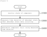
- FIG. 3 is a flowchart illustrating a method of diagnosing a battery system according to embodiments of the present invention.
- the diagnosing apparatus 1000 may monitor the state of at least one component constituting the battery system (S1000).
- the diagnosing apparatus 1000 may analyze at least one state data for a battery cell or battery module and at least one electrical component included in a battery system by operations of the processor 200, and monitor whether any abnormalities occur therein.
- the diagnosing apparatus 1000 may measure time duration of the abnormal state (S3000). For example, when the diagnosing apparatus 1000 receives abnormal state data for one component, the diagnosing apparatus may determine the time duration from a generation time of the abnormal state data to an end time of the abnormal state data as the time duration of the abnormal state.
- the time duration of the abnormal state may mean a time continuously measured from the time when abnormal state data first occurs to the time when the abnormal state data ends.
- the time duration of the abnormal state may be defined as the time duration from the first time occurrence to the last time occurrence when abnormal state data occurs more than a preset number of times.
- the time duration of the abnormal state according to the present invention is not limited to this and may be defined based on abnormal state data for a corresponding component.
- the diagnosing apparatus 1000 may determine whether a component has a fault based on the measured time duration of the abnormal state (S5000). The method of determining whether a component has failed based on the time duration of the abnormal state will be described in more detail with reference to FIGS. 4 and 5 below.
- FIG. 4 is a flowchart illustrating a method of determining whether a malfunction is present in the component in the method of diagnosing a battery system according to embodiments of the present invention.
- the diagnosing apparatus 1000 may determine whether a component has a fault by comparing the time duration of the abnormal state with a preset reference time duration.
- the diagnosing apparatus 1000 may compare the time duration of the abnormal state with a reference time duration and may determine that the component is out of order if the time duration of the abnormal state is longer than or equal to the reference time duration (S5100).
- the diagnosing apparatus 1000 may check whether the time duration of the abnormal state satisfies the early stage diagnosis condition (S5300).
- the diagnosing apparatus 1000 may determine that the component is out of order.
- the diagnosing apparatus 1000 may terminate the diagnosis of whether the component is out of order, return to step S1000, and continuously perform state monitoring.
- FIG. 5 is a flowchart illustrating an early stage diagnosis condition in the method of diagnosing a battery system according to embodiments of the present invention.
- the diagnosing apparatus 1000 may check whether the time duration of the abnormal state satisfies the early stage diagnosis condition when the time duration of the abnormal state is shorter than the reference time duration, as in step S5300 described above.
- the early stage diagnosis condition may include at least one of the first condition, the second condition, and the third condition.
- the first condition may be defined as a state in which a number of occurrences of an abnormal state is greater than or equal to a predefined first threshold.
- the second condition may be defined as a state in which the time duration of the abnormal state of the component exceeds a pre-stored longest time duration and the third condition may be defined as a state in which the time duration of the abnormal state of the component is greater than or equal to a preset second threshold.
- the diagnosing apparatus 1000 may determine that a failure has occurred in the component (S5500).
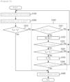
- FIG. 6 is a flowchart illustrating a method of diagnosing a battery system according to embodiments of the present invention.
- the diagnosing apparatus 1000 may monitor whether an abnormal state occurs in at least one component constituting the battery system (S100).
- the diagnosing apparatus 1000 may measure time duration of the abnormal state (S300).
- the diagnosing apparatus 1000 may compare the time duration of the abnormal state (Tc) with a preset reference time (Ts) (S310).
- the diagnosing apparatus may determine that the component has failed (S400).
- the diagnosing apparatus 1000 may check whether the time duration of the abnormal state (Tc) satisfies the early stage diagnosis condition (S330).
- the diagnosing apparatus 1000 may check whether the time duration of the abnormal state (Tc) satisfies minimum time duration (S331).
- the minimum time duration may be set by a user based on previously generated failure history data.
- the minimum time duration may be defined as a range from 0.4 times or more to less than 0.6 times the reference time duration.
- the minimum time duration may be 0.5 times the reference time duration.
- the diagnosing apparatus 1000 may check whether the counted number of occurrences of the abnormal state (N) is greater than or equal to a first threshold (S333).
- the first threshold may be set by a user.
- the first threshold may be defined as 5 times.
- the diagnosing apparatus 1000 may compare the time duration of the abnormal state (T C ) with the longest time duration (T L ) of the abnormal state that has previously occurred in the component (S334).
- the longest time duration (T L ) may be defined as the longest time duration among time durations (T C ) of an abnormal state that has previously occurred in the component.
- the diagnosing apparatus 1000 may update the longest maintenance time (T L ) with the time duration (T C ) of the abnormal state (S335).
- the diagnosing apparatus 1000 may check whether the longest time duration (T L ) is equal to or greater than a second threshold (S336).
- the second threshold may be defined in the range of 0.7 to 0.9 times the reference time duration.
- the second threshold may be 0.8 times the reference time duration.
- the diagnosing apparatus 1000 may determine that the component has a fault (S400).
- the diagnosing apparatus may return to step S100 and perform state monitoring of the component.
- a diagnosing apparatus and method for diagnosing a failure of a component included in a battery system may monitor whether an abnormal state of the component occurs based on abnormal state data of the component, upon abnormal state occurring in the component, measure a time duration for which the abnormal state is maintained, compare the time duration for which the abnormal state is maintained to a preset reference time duration, and, upon the time duration for which the abnormal state is maintained being shorter than the reference time duration, check whether a predetermined early stage diagnosis condition is satisfied based on the time duration for which the abnormal state is maintained and determining whether or not a component failure has occurred according to whether or not the early stage diagnosis condition is satisfied, thereby enabling preemptive response by early stage diagnosis of failure even for temporary abnormal state data which lasts shorter than a preset reference time and providing high-performance, high-precision, high-efficiency, and high-reliability diagnostic devices and methods.
- the operations of the method according to the embodiments of the present invention may be implemented as a computer-readable program or code on a computer-readable recording medium.
- the computer-readable recording medium includes all types of recording devices in which data readable by a computer system is stored.
- the computer-readable recording medium may be distributed in a network-connected computer system to store and execute computer-readable programs or codes in a distributed manner.
- the computer-readable recording medium may include hardware devices specially configured to store and execute program instructions, such as ROM, RAM, flash memory, etc.
- the program instructions may include not only machine language code created by a compiler, but also high-level language code that can be executed by a computer using an interpreter.
- a block or apparatus corresponds to a method step or feature of a method step.
- aspects described in the context of a method may also represent a feature of a corresponding block or item or a corresponding apparatus.
- Some or all of the method steps may be performed by (or using) a hardware device, such as, for example, a microprocessor, a programmable computer, or an electronic circuit. In some embodiments, one or more of the most important method steps may be performed by such an apparatus.
Landscapes
- Engineering & Computer Science (AREA)
- Physics & Mathematics (AREA)
- General Physics & Mathematics (AREA)
- Manufacturing & Machinery (AREA)
- Chemical & Material Sciences (AREA)
- Chemical Kinetics & Catalysis (AREA)
- Electrochemistry (AREA)
- General Chemical & Material Sciences (AREA)
- Sustainable Energy (AREA)
- Sustainable Development (AREA)
- Life Sciences & Earth Sciences (AREA)
- Power Engineering (AREA)
- Transportation (AREA)
- Mechanical Engineering (AREA)
- Microelectronics & Electronic Packaging (AREA)
- Secondary Cells (AREA)
- Charge And Discharge Circuits For Batteries Or The Like (AREA)
- Testing Electric Properties And Detecting Electric Faults (AREA)
- Tests Of Electric Status Of Batteries (AREA)
- Protection Of Static Devices (AREA)
Abstract
Description
- This application claims priority to and the benefit of
Korean Patent Application No.10-2022-0096681 filed in the Korean Intellectual Property Office on August 03, 2022 - The present invention relates to an apparatus and method for diagnosing a battery system, and more particularly, to an apparatus and method for diagnosing a fault in a component included in a battery system.
- Recently, due to depletion of fossil energy and environmental pollution, interest in electric vehicles using electric energy without using fossil energy is increasing.
- In general, an electric vehicle operates a drive motor that requires high output for driving. Accordingly, an electric vehicle uses a battery pack in which a plurality of battery cells are connected in series and uses electricity output from the battery pack as an energy source.
- In other words, since the performance of a battery directly affects the performance of a vehicle using electric energy, it is essentially required to monitor states of battery cells and electric components by measuring voltage and current states of battery cells and operating states of electric components.
- Meanwhile, when an abnormality occurs in at least one hardware component in an electric vehicle, a conventional diagnosing apparatus determines it as a failure only when the abnormality continuously occurs for a preset maintaining time.
- In a conventional diagnosing apparatus, when the maintaining time is set to be long, minor failures in components cannot be detected, which leads to a disadvantage of making preemptive diagnosis difficult, whereas when the maintaining time is set to be short, noise signals from the external environment may be misdetected as a failure, which leads to a disadvantage of lowering reliability.
- To obviate one or more problems of the related art, embodiments of the present disclosure provide an apparatus of diagnosing a battery system with high-performance, high-precision, high-efficiency, and high-reliability.
- To obviate one or more problems of the related art, embodiments of the present disclosure also provide a method of diagnosing a battery system with high-performance, high-precision, high-efficiency, and high-reliability.
- In order to achieve the objective of the present disclosure, a diagnosing method of a battery system, for diagnosing an abnormality in a component included in the battery system, may include monitoring whether an abnormal state of the component occurs based on abnormal state data of the component; upon abnormal state occurring in the component, measuring a time duration for which the abnormal state is maintained; comparing the time duration for which the abnormal state is maintained to a preset reference time duration; and upon the time duration for which the abnormal state is maintained being shorter than the reference time duration, checking whether a predetermined early stage diagnosis condition is satisfied according to the time duration for which the abnormal state is maintained and determining whether or not a component failure has occurred according to whether or not the early stage diagnosis condition is satisfied.
- The determining whether or not a component failure has occurred may include: checking whether the early stage diagnosis condition is satisfied, wherein the early stage diagnosis condition is defined by including at least one of a first condition in which a number of abnormal state occurrences is greater than or equal to a predefined first threshold, a second condition in which the time duration for which the abnormal state is maintained exceeds a previously stored longest time duration, and a third condition in which the time duration for which the abnormal state is maintained is longer than or equal to a predetermined second threshold.
- The determining whether or not a component failure has occurred may include: counting the number of abnormal state occurrences when the time duration for which the abnormal state is maintained is longer than or equal to a predetermined minimum time duration.
- The predetermined minimum time duration may be defined as a range of 0.4 times to 0.6 times the reference time duration.
- The determining whether or not a component failure has occurred may include: updating the longest time duration with the time duration for which the abnormal state is maintained in the instance that the time duration for which the abnormal state is maintained exceeds the previously stored longest time duration.
- The second threshold may be defined as a range of 0.7 times to 0.9 times the reference time duration.
- The diagnosing method of the battery system may further include determining that a component failure has occurred in the instance that the time duration for which the abnormal state is maintained is longer than or equal to the reference time duration.
- The determining whether or not a component failure has occurred may include determining that a component failure has occurred using early stage diagnosis in the instance that the first condition, the second condition, and the third condition are satisfied even if the time duration for which the abnormal state is maintained is shorter than the reference time duration.
- According to another embodiment of the present disclosure, a diagnosing apparatus of a battery system for diagnosing an abnormality in a component included in the battery system may include at least one processor and a memory configured to store at least one instruction executed by the at least one processor, and the at least one instruction may include: an instruction to monitor whether an abnormal state of the component occurs based on abnormal state data of the component; an instruction to, upon abnormal state occurring in the component, measure a time duration for which the abnormal state is maintained; an instruction to compare the time duration for which the abnormal state is maintained to a preset reference time duration; and an instruction to, upon the time duration for which the abnormal state is maintained being shorter than the reference time duration, check whether a predetermined early stage diagnosis condition is satisfied based on the time duration for which the abnormal state is maintained and determine whether or not a component failure has occurred according to whether or not the early stage diagnosis condition is satisfied.
- Furthermore, the at least one instruction may include an instruction to check whether the early stage diagnosis condition is satisfied, wherein the early stage diagnosis condition is defined by including at least one of a first condition in which a number of abnormal state occurrences is greater than or equal to a predefined first threshold, a second condition in which the time duration for which the abnormal state is maintained exceeds a previously stored longest time duration, and a third condition in which the time duration for which the abnormal state is maintained is longer than or equal to a predetermined second threshold.
- In addition, the at least one instruction may include an instruction to count the number of abnormal state occurrences when the time duration for which the abnormal state is maintained is longer than or equal to a predetermined minimum time duration.
- Here, the predetermined minimum time duration may be defined as a range of 0.4 times to 0.6 times the reference time duration.
- Furthermore, the at least one instruction may include an instruction to update the longest time duration with the time duration for which the abnormal state is maintained in the instance that the time duration for which the abnormal state is maintained exceeds the previously stored longest time duration.
- Meanwhile, the second threshold may be defined as a range of 0.7 times to 0.9 times the reference time duration.
- Furthermore, the at least one instruction may further include an instruction to determine that a component failure has occurred in the instance that the time duration for which the abnormal state is maintained is longer than or equal to the reference time duration.
- In addition, the at least one instruction may include an instruction to determine that a component failure has occurred using early stage diagnosis in the instance that the first condition, the second condition, and the third condition are satisfied even if the time duration for which the abnormal state is maintained is shorter than the reference time duration.
- According to embodiments of the present invention, a diagnosing apparatus and method for diagnosing a failure of a component included in a battery system may monitor whether an abnormal state of the component occurs based on abnormal state data of the component, upon abnormal state occurring in the component, measure a time duration for which the abnormal state is maintained, compare the time duration for which the abnormal state is maintained to a preset reference time duration, and, upon the time duration for which the abnormal state is maintained being shorter than the reference time duration, check whether a predetermined early stage diagnosis condition is satisfied based on the time duration for which the abnormal state is maintained and determining whether or not a component failure has occurred according to whether or not the early stage diagnosis condition is satisfied, thereby enabling preemptive response by early stage diagnosis of failure even for temporary abnormal state data which lasts shorter than a preset reference time and providing high-performance, high-precision, high-efficiency, and high-reliability diagnostic devices and methods.
-
-
FIG. 1 is a block diagram of a battery system to which embodiments of the present invention may be applied. -
FIG. 2 is a block diagram of a diagnosing apparatus of a battery system according to embodiments of the present invention. -
FIG. 3 is a flowchart illustrating a method of diagnosing a battery system according to embodiments of the present invention. -
FIG. 4 is a flowchart illustrating a method of determining whether a malfunction is present in the component in the method of diagnosing a battery system according to embodiments of the present invention. -
FIG. 5 is a flowchart illustrating an early stage diagnosis condition in the method of diagnosing a battery system according to embodiments of the present invention. -
FIG. 6 is a flowchart illustrating a method of diagnosing a battery system according to embodiments of the present invention. - 1000: diagnosing apparatus of battery system
- 100: memory 200: processor
- 300: transceiver device
- 400: input interface device
- 500: output interface device
- 600: storage device
- 700: bus
- The present invention may be modified in various forms and have various embodiments, and specific embodiments thereof are shown by way of example in the drawings and will be described in detail below. It should be understood, however, that there is no intent to limit the present invention to the specific embodiments, but on the contrary, the present invention is to cover all modifications, equivalents, and alternatives falling within the spirit and technical scope of the present invention. Like reference numerals refer to like elements throughout the description of the figures.
- It will be understood that, although the terms such as first, second, A, B, and the like may be used herein to describe various elements, these elements should not be limited by these terms. These terms are only used to distinguish one element from another. For example, a first element could be termed a second element, and, similarly, a second element could be termed a first element, without departing from the scope of the present invention. As used herein, the term "and/or" includes combinations of a plurality of associated listed items or any of the plurality of associated listed items.
- It will be understood that when an element is referred to as being "coupled" or "connected" to another element, it can be directly coupled or connected to the other element or an intervening element may be present. In contrast, when an element is referred to as being "directly coupled" or "directly connected" to another element, there is no intervening element present.
- The terms used herein is for the purpose of describing specific embodiments only and are not intended to limit the present invention. As used herein, the singular forms "a", "an" and "the" are intended to include the plural forms as well, unless the context clearly indicates otherwise. It will be further understood that the terms "comprises", "comprising", "includes", "including" and/or "having", when used herein, specify the presence of stated features, integers, steps, operations, constitutional elements, components and/or combinations thereof, but do not preclude the presence or addition of one or more other features, integers, steps, operations, constitutional elements, components, and/or combinations thereof.
- Unless otherwise defined, all terms used herein, including technical and scientific terms, have the same meanings as commonly understood by one skilled in the art to which the present invention belongs. It will be further understood that terms, such as those defined in commonly used dictionaries, should be interpreted as having meanings that are consistent with their meanings in the context of the relevant art and will not be interpreted in an idealized or overly formal sense unless expressly so defined herein.
- Hereinafter, exemplary embodiments of the present invention will be described in detail with reference to the accompanying drawings.
-
FIG. 1 is a block diagram of a battery system to which embodiments of the present invention may be applied. - Referring to
FIG. 1 , a battery pack or battery module may include a plurality of battery cells connected in series. The battery pack or module may be connected to a load through a positive terminal and a negative terminal to perform charging or discharging. The most commonly used battery cell is a lithium-ion (Li-Ion) battery cell. - A battery management system (BMS) may be connected to a battery module or battery pack.
- The battery management system may monitor a current, a voltage and a temperature of each battery cell or module to be managed, calculate a state of charge (SOC) of the battery based on monitoring results to control charging and discharging. Here, the State of Charge (SOC) refers to a current state of charge of a battery, represented in percent points [%], and the State of Health (SOH) may be a current condition of a battery compared to its ideal conditions, represented in percent points [%].
- The BMS may monitor battery cells, read cell voltages, and transmit them to other systems connected to the battery.
- Furthermore, the battery management system monitors at least one electrical component constituting the battery system and passes their status data on to other systems. For this, the BMS includes a communication module for communicating with other systems in a device including the battery system.
- The communication module of the BMS can communicate with other systems in the device using CAN (Controller Area Network). Here, components, modules or systems in the BMS are connected to each other through a CAN bus. Accordingly, the battery management system (BMS) may use CAN communication to remotely transmit status data obtained through monitoring of the battery pack or module and at least one electrical component constituting the battery management system (BMS) to other systems.
- Furthermore, the battery management system (BMS) may equally balance charges of the battery cells in order to extend the life of the battery system.
- The BMS may include various components such as a fuse, a current sensing element, a thermistor, a switch, and a balancer to perform such operations. In most cases, a micro controller unit (MCU) or a battery monitoring integrated chip (BMIC) for interworking and controlling these components is additionally included in the BMS. Here, the BMIC may be located inside the BMS and may be an integrated circuit (IC) type component that measures information such as voltage, temperature, and current of a battery cell/module. According to embodiments, a battery management system (BMS) may be applied to a vehicle.
- Meanwhile, in general, a battery management system (BMS) may be interlocked with a battery protection device, which blocks a charge/discharge circuit when an abnormality occurs in a battery. In other words, when an abnormality occurs in any one battery cell or module, the conventional battery protection circuit blocks the charge/discharge circuit to limit use of the battery.
-
FIG. 2 is a block diagram of a diagnosing apparatus of a battery system according to embodiments of the present invention. - Referring to
FIG. 2 , the diagnosing apparatus of abattery system 1000 may be a component of the battery management system (BMS). Accordingly, thediagnosis apparatus 1000 may diagnose a failure occurring in a component included in the battery system. Here, the component included in the battery system may be any one of a battery cell, a battery module, and at least one electric component therein. - In more detail, the diagnosing apparatus of a
battery system 1000 may monitor whether or not abnormal state data outside a preset condition value is generated based on state data transmitted from at least one component included in the battery system. - In addition, the
diagnosis apparatus 1000 can diagnose whether or not a corresponding component has a failure at an early stage based on an anomaly that occurs while monitoring the state of a component. - More specifically, when abnormal state data out of a preset condition range is generated in a component included in the battery system, the diagnosing
apparatus 1000 of a battery system may measure a time duration during which the abnormal state data is continuously maintained. Thereafter, when the time duration during which the abnormal state data is maintained is shorter than a predetermined reference time duration and an early stage diagnosis condition is satisfied, the diagnosingapparatus 1000 of a battery system may diagnose whether the component is out of order at an early stage based on the time duration. - In contrast, generally, when abnormal state data is generated in any one of at least one component constituting the battery system, a typical diagnosing apparatus diagnoses that the corresponding component is out of order only when the abnormal state data lasts longer than a predetermined reference time duration. In other words, as to the typical diagnosing apparatus, the reliability of the diagnosis result or the stability of use is determined according to a set reference time duration.
- For example, in more detail, when the reference time duration is set short in a typical diagnosing apparatus to increase safety of at least one component constituting the battery system, abnormal state data may be generated by temporary noise phenomena and the corresponding component may be mistakenly judged as having failure because of the abnormal state data, resulting in decreased reliability.
- In contrast, when setting a long reference time duration to ignore abnormal state data generated by temporary noise in order to increase reliability, the typical diagnosing apparatus cannot detect abnormal state data caused by failures early, which renders a preemptive response difficult.
- Meanwhile, the battery
system diagnosing apparatus 1000 according to embodiments of the present invention may determine a failure, like a conventional diagnosis apparatus, when the time duration of abnormal state data for at least one component included in the battery system is equal to or longer than a predetermined reference time. In addition, even when the time duration of the abnormal state data is shorter than the reference time, it is possible to preemptively respond to a failure by determining whether the component has a failure according to whether an early stage diagnosis condition is satisfied. - In more detail, as to each component of the battery
system diagnosing apparatus 1000 according to embodiments of the present invention, the batterysystem diagnosing apparatus 1000 may include amemory 100, aprocessor 200, atransceiver device 300, aninput interface device 400, anoutput interface device 500, and astorage device 600. - According to embodiments,
respective components apparatus 1000 may be connected by abus 700 to communicate with each other. - The
memory 100 and thestorage device 600 among thecomponents memory 100 and thestorage device 600 may include at least one of read only memory (ROM) and random access memory (RAM). - Among them, the
memory 100 may include at least one instruction executed by theprocessor 200. - According to embodiments, the at least one instruction may include: an instruction to monitor whether an abnormal state of the component occurs based on abnormal state data of the component; an instruction to, upon abnormal state occurring in the component, measure a time duration for which the abnormal state is maintained; an instruction to compare the time duration for which the abnormal state is maintained to a preset reference time duration; and an instruction to, upon the time duration for which the abnormal state is maintained being shorter than the reference time duration, check whether a predetermined early stage diagnosis condition is satisfied based on the time duration for which the abnormal state is maintained and determine whether or not a component failure has occurred according to whether or not the early stage diagnosis condition is satisfied.
- Furthermore, the at least one instruction may include an instruction to check whether the early stage diagnosis condition is satisfied, wherein the early stage diagnosis condition is defined by including at least one of a first condition in which a number of abnormal state occurrences is greater than or equal to a predefined first threshold, a second condition in which the time duration for which the abnormal state is maintained exceeds a previously stored longest time duration, and a third condition in which the time duration for which the abnormal state is maintained is longer than or equal to a predetermined second threshold.
- In addition, the at least one instruction may include an instruction to count the number of abnormal state occurrences when the time duration for which the abnormal state is maintained is longer than or equal to a predetermined minimum time duration.
- Here, the predetermined minimum time duration may be defined as a range of 0.4 times to 0.6 times the reference time duration.
- Furthermore, the at least one instruction may include an instruction to update the longest time duration with the time duration for which the abnormal state is maintained in the instance that the time duration for which the abnormal state is maintained exceeds the previously stored longest time duration.
- Meanwhile, the second threshold may be defined as a range of 0.7 times to 0.9 times the reference time duration.
- Furthermore, the at least one instruction may further include an instruction to determine that a component failure has occurred in the instance that the time duration for which the abnormal state is maintained is longer than or equal to the reference time duration.
- In addition, the at least one instruction may include an instruction to determine that a component failure has occurred using early stage diagnosis in the instance that the first condition, the second condition, and the third condition are satisfied even if the time duration for which the abnormal state is maintained is shorter than the reference time duration.
- Meanwhile, the
processor 200 may mean a central processing unit (CPU), a graphics processing unit (GPU), or a dedicated processor on which methods according to embodiments of the present invention are performed. - The
processor 200 may execute at least one program command stored in thememory 100 as described above. - The diagnosing apparatus according to embodiments of the present invention has been described above. Hereinafter, a method of diagnosing a battery system performed by process operations of the diagnosing apparatus will be described.
-
FIG. 3 is a flowchart illustrating a method of diagnosing a battery system according to embodiments of the present invention. - Referring to
FIG. 3 , the diagnosingapparatus 1000 according to embodiments of the present invention may monitor the state of at least one component constituting the battery system (S1000). - To be more specific, the diagnosing
apparatus 1000 may analyze at least one state data for a battery cell or battery module and at least one electrical component included in a battery system by operations of theprocessor 200, and monitor whether any abnormalities occur therein. - Thereafter, when an abnormal state occurs in any one component, the diagnosing
apparatus 1000 may measure time duration of the abnormal state (S3000). For example, when the diagnosingapparatus 1000 receives abnormal state data for one component, the diagnosing apparatus may determine the time duration from a generation time of the abnormal state data to an end time of the abnormal state data as the time duration of the abnormal state. - According to one embodiment, the time duration of the abnormal state may mean a time continuously measured from the time when abnormal state data first occurs to the time when the abnormal state data ends.
- According to another embodiment, the time duration of the abnormal state may be defined as the time duration from the first time occurrence to the last time occurrence when abnormal state data occurs more than a preset number of times.
- However, the time duration of the abnormal state according to the present invention is not limited to this and may be defined based on abnormal state data for a corresponding component.
- Thereafter, the diagnosing
apparatus 1000 may determine whether a component has a fault based on the measured time duration of the abnormal state (S5000). The method of determining whether a component has failed based on the time duration of the abnormal state will be described in more detail with reference toFIGS. 4 and5 below. -
FIG. 4 is a flowchart illustrating a method of determining whether a malfunction is present in the component in the method of diagnosing a battery system according to embodiments of the present invention. - Referring to
FIG. 4 , the diagnosingapparatus 1000 may determine whether a component has a fault by comparing the time duration of the abnormal state with a preset reference time duration. - More specifically, the diagnosing
apparatus 1000 may compare the time duration of the abnormal state with a reference time duration and may determine that the component is out of order if the time duration of the abnormal state is longer than or equal to the reference time duration (S5100). - Meanwhile, if the time duration of the abnormal state is shorter than the reference time duration, the diagnosing
apparatus 1000 may check whether the time duration of the abnormal state satisfies the early stage diagnosis condition (S5300). - According to an embodiment, when the time duration of the abnormal state satisfies the early stage diagnosis condition, the diagnosing
apparatus 1000 may determine that the component is out of order. - According to another embodiment, if the time duration of the abnormal state does not satisfy the early stage diagnosis condition, the diagnosing
apparatus 1000 may terminate the diagnosis of whether the component is out of order, return to step S1000, and continuously perform state monitoring. -
FIG. 5 is a flowchart illustrating an early stage diagnosis condition in the method of diagnosing a battery system according to embodiments of the present invention. - Referring to
FIG. 5 , the diagnosingapparatus 1000 may check whether the time duration of the abnormal state satisfies the early stage diagnosis condition when the time duration of the abnormal state is shorter than the reference time duration, as in step S5300 described above. - Here, the early stage diagnosis condition may include at least one of the first condition, the second condition, and the third condition.
- More specifically, the first condition may be defined as a state in which a number of occurrences of an abnormal state is greater than or equal to a predefined first threshold. Additionally, the second condition may be defined as a state in which the time duration of the abnormal state of the component exceeds a pre-stored longest time duration and the third condition may be defined as a state in which the time duration of the abnormal state of the component is greater than or equal to a preset second threshold.
- If the first to third conditions are all satisfied (S5310, 5330, and S5350), the diagnosing
apparatus 1000 may determine that a failure has occurred in the component (S5500). -
FIG. 6 is a flowchart illustrating a method of diagnosing a battery system according to embodiments of the present invention. - Referring to
FIG. 6 , the diagnosingapparatus 1000 according to embodiments of the present invention may monitor whether an abnormal state occurs in at least one component constituting the battery system (S100). - Thereafter, when an abnormal state occurs in any one component, the diagnosing
apparatus 1000 may measure time duration of the abnormal state (S300). - The diagnosing
apparatus 1000 may compare the time duration of the abnormal state (Tc) with a preset reference time (Ts) (S310). - According to one embodiment, when the time duration of the abnormal state (Tc) is greater than or equal to a reference time duration, the diagnosing apparatus may determine that the component has failed (S400).
- According to another embodiment, when the time duration of the abnormal state (Tc) is less than the reference time duration, the diagnosing
apparatus 1000 may check whether the time duration of the abnormal state (Tc) satisfies the early stage diagnosis condition (S330). - In more detail, the diagnosing
apparatus 1000 may check whether the time duration of the abnormal state (Tc) satisfies minimum time duration (S331). Here, the minimum time duration may be set by a user based on previously generated failure history data. For example, the minimum time duration may be defined as a range from 0.4 times or more to less than 0.6 times the reference time duration. According to an embodiment, the minimum time duration may be 0.5 times the reference time duration. - Here, if the time duration of the abnormal state (Tc) satisfies the minimum time duration, the diagnosing
apparatus 1000 may count a number (N) of abnormal state occurrences of the component (N=N+1) (S332). - Thereafter, the diagnosing
apparatus 1000 may check whether the counted number of occurrences of the abnormal state (N) is greater than or equal to a first threshold (S333). Here, the first threshold may be set by a user. For example, the first threshold may be defined as 5 times. - When the number of occurrences of the abnormal state (N) is greater than or equal to the first threshold, the diagnosing
apparatus 1000 may compare the time duration of the abnormal state (TC) with the longest time duration (TL) of the abnormal state that has previously occurred in the component (S334). Here, the longest time duration (TL) may be defined as the longest time duration among time durations (TC) of an abnormal state that has previously occurred in the component. When the time duration (TC) of the abnormal state of the component exceeds the longest maintenance time (TL) previously generated in the component, the diagnosingapparatus 1000 may update the longest maintenance time (TL) with the time duration (TC) of the abnormal state (S335). - Thereafter, the diagnosing
apparatus 1000 may check whether the longest time duration (TL) is equal to or greater than a second threshold (S336). According to an embodiment, the second threshold may be defined in the range of 0.7 to 0.9 times the reference time duration. For example, the second threshold may be 0.8 times the reference time duration. - When the time duration (TC) of the abnormal state exceeds the second threshold value, the diagnosing
apparatus 1000 may determine that the component has a fault (S400). - Meanwhile, if any of the conditions in steps S331, S333, S334, and S336 is not satisfied, the diagnosing apparatus according to embodiments of the present invention may return to step S100 and perform state monitoring of the component.
- The diagnosing apparatus and method for a battery system according to an embodiment of the present invention have been described above.
- According to embodiments of the present invention, a diagnosing apparatus and method for diagnosing a failure of a component included in a battery system may monitor whether an abnormal state of the component occurs based on abnormal state data of the component, upon abnormal state occurring in the component, measure a time duration for which the abnormal state is maintained, compare the time duration for which the abnormal state is maintained to a preset reference time duration, and, upon the time duration for which the abnormal state is maintained being shorter than the reference time duration, check whether a predetermined early stage diagnosis condition is satisfied based on the time duration for which the abnormal state is maintained and determining whether or not a component failure has occurred according to whether or not the early stage diagnosis condition is satisfied, thereby enabling preemptive response by early stage diagnosis of failure even for temporary abnormal state data which lasts shorter than a preset reference time and providing high-performance, high-precision, high-efficiency, and high-reliability diagnostic devices and methods.
- The operations of the method according to the embodiments of the present invention may be implemented as a computer-readable program or code on a computer-readable recording medium. The computer-readable recording medium includes all types of recording devices in which data readable by a computer system is stored. In addition, the computer-readable recording medium may be distributed in a network-connected computer system to store and execute computer-readable programs or codes in a distributed manner.
- In addition, the computer-readable recording medium may include hardware devices specially configured to store and execute program instructions, such as ROM, RAM, flash memory, etc. The program instructions may include not only machine language code created by a compiler, but also high-level language code that can be executed by a computer using an interpreter.
- Although some aspects of the invention have been described in the context of the apparatus, it may also represent a description according to a corresponding method, wherein a block or apparatus corresponds to a method step or feature of a method step. Similarly, aspects described in the context of a method may also represent a feature of a corresponding block or item or a corresponding apparatus. Some or all of the method steps may be performed by (or using) a hardware device, such as, for example, a microprocessor, a programmable computer, or an electronic circuit. In some embodiments, one or more of the most important method steps may be performed by such an apparatus.
- In the forgoing, the present invention has been described with reference to the exemplary embodiment of the present invention, but those skilled in the art may appreciate that the present invention may be variously corrected and changed within the range without departing from the spirit and the area of the present invention described in the appending claims.
Claims (16)
- A diagnosing method of a battery system for diagnosing an abnormality in a component included in the battery system, the diagnosing method of the battery system comprising:monitoring whether an abnormal state of the component occurs based on abnormal state data of the component;upon abnormal state occurring in the component, measuring a time duration for which the abnormal state is maintained;comparing the time duration for which the abnormal state is maintained to a preset reference time duration; andupon the time duration for which the abnormal state is maintained being shorter than the reference time duration, checking whether a predetermined early stage diagnosis condition is satisfied according to the time duration for which the abnormal state is maintained and determining whether or not a component failure has occurred according to whether or not the early stage diagnosis condition is satisfied.
- The diagnosing method of the battery system of claim 1, wherein the determining whether or not a component failure has occurred includes:
checking whether the early stage diagnosis condition is satisfied, wherein the early stage diagnosis condition is defined by including at least one of a first condition in which a number of abnormal state occurrences is greater than or equal to a predefined first threshold, a second condition in which the time duration for which the abnormal state is maintained exceeds a previously stored longest time duration, and a third condition in which the time duration for which the abnormal state is maintained is longer than or equal to a predetermined second threshold. - The diagnosing method of the battery system of claim 2, wherein the determining whether or not a component failure has occurred includes:
counting the number of abnormal state occurrences when the time duration for which the abnormal state is maintained is longer than or equal to a predetermined minimum time duration. - The diagnosing method of the battery system of claim 3, wherein the predetermined minimum time duration is defined as a range of 0.4 times to 0.6 times the reference time duration.
- The diagnosing method of the battery system of claim 2, wherein the determining whether or not a component failure has occurred includes:
updating the longest time duration with the time duration for which the abnormal state is maintained in the instance that the time duration for which the abnormal state is maintained exceeds the previously stored longest time duration. - The diagnosing method of the battery system of claim 2, wherein the second threshold is defined as a range of 0.7 times to 0.9 times the reference time duration.
- The diagnosing method of the battery system of claim 2, further comprising:
determining that a component failure has occurred in the instance that the time duration for which the abnormal state is maintained is longer than or equal to the reference time duration. - The diagnosing method of the battery system of claim 2, wherein the determining whether or not a component failure has occurred includes:
determining that a component failure has occurred using early stage diagnosis in the instance that the first condition, the second condition, and the third condition are satisfied even if the time duration for which the abnormal state is maintained is shorter than the reference time duration. - A diagnosing apparatus of a battery system for diagnosing an abnormality in a component included in the battery system, the apparatus comprising:at least one processor; anda memory configured to store at least one instruction executed by the at least one processor,wherein the at least one instruction includes:an instruction to monitor whether an abnormal state of the component occurs based on abnormal state data of the component;an instruction to, upon abnormal state occurring in the component, measure a time duration for which the abnormal state is maintained;an instruction to compare the time duration for which the abnormal state is maintained to a preset reference time duration; andan instruction to, upon the time duration for which the abnormal state is maintained being shorter than the reference time duration, check whether a predetermined early stage diagnosis condition is satisfied according to the time duration for which the abnormal state is maintained and determine whether or not a component failure has occurred according to whether or not the early stage diagnosis condition is satisfied.
- The diagnosing apparatus of the battery system of claim 9, wherein the at least one instruction includes:
an instruction to check whether the early stage diagnosis condition is satisfied, wherein the early stage diagnosis condition is defined by including at least one of a first condition in which a number of abnormal state occurrences is greater than or equal to a predefined first threshold, a second condition in which the time duration for which the abnormal state is maintained exceeds a previously stored longest time duration, and a third condition in which the time duration for which the abnormal state is maintained is longer than or equal to a predetermined second threshold. - The diagnosing apparatus of the battery system of claim 10, wherein the at least one instruction includes:
an instruction to count the number of abnormal state occurrences when the time duration for which the abnormal state is maintained is longer than or equal to a predetermined minimum time duration. - The diagnosing apparatus of the battery system of claim 11, wherein the predetermined minimum time duration is defined as a range of 0.4 times to 0.6 times the reference time duration.
- The diagnosing apparatus of the battery system of claim 10, wherein the at least one instruction includes:
an instruction to update the longest time duration with the time duration for which the abnormal state is maintained in the instance that the time duration for which the abnormal state is maintained exceeds the previously stored longest time duration. - The diagnosing apparatus of the battery system of claim 10, wherein the second threshold is defined as a range of 0.7 times to 0.9 times the reference time duration.
- The diagnosing apparatus of the battery system of claim 10, wherein the at least one instruction further includes:
an instruction to determine that a component failure has occurred in the instance that the time duration for which the abnormal state is maintained is longer than or equal to the reference time duration. - The diagnosing apparatus of the battery system of claim 10, wherein the at least one instruction includes:
an instruction to determine that a component failure has occurred using early stage diagnosis in the instance that the first condition, the second condition, and the third condition are satisfied even if the time duration for which the abnormal state is maintained is shorter than the reference time duration.
Applications Claiming Priority (2)
| Application Number | Priority Date | Filing Date | Title |
|---|---|---|---|
| KR1020220096681A KR102966013B1 (en) | 2022-08-03 | Apparatus and method for diagnosing of battery system | |
| PCT/KR2023/009313 WO2024029754A1 (en) | 2022-08-03 | 2023-07-03 | Diagnosis device and method for battery system |
Publications (3)
| Publication Number | Publication Date |
|---|---|
| EP4459298A1 true EP4459298A1 (en) | 2024-11-06 |
| EP4459298A4 EP4459298A4 (en) | 2025-07-02 |
| EP4459298B1 EP4459298B1 (en) | 2026-04-15 |
Family
ID=89849089
Family Applications (1)
| Application Number | Title | Priority Date | Filing Date |
|---|---|---|---|
| EP23850264.5A Active EP4459298B1 (en) | 2022-08-03 | 2023-07-03 | Diagnosis device and method for battery system |
Country Status (5)
| Country | Link |
|---|---|
| US (1) | US20250155508A1 (en) |
| EP (1) | EP4459298B1 (en) |
| JP (1) | JP2025504417A (en) |
| CN (1) | CN118647882A (en) |
| WO (1) | WO2024029754A1 (en) |
Family Cites Families (12)
| Publication number | Priority date | Publication date | Assignee | Title |
|---|---|---|---|---|
| JPH01234018A (en) * | 1988-03-11 | 1989-09-19 | Fujitsu Ten Ltd | Power ic |
| KR20020049282A (en) * | 2000-12-19 | 2002-06-26 | 이계안 | A malfunction detecting method of battery back up line for an electronic control unit |
| JP4454187B2 (en) * | 2001-06-22 | 2010-04-21 | 大阪瓦斯株式会社 | Power supply |
| JP4942143B2 (en) * | 2005-12-15 | 2012-05-30 | 東芝三菱電機産業システム株式会社 | Inverter device and overvoltage protection method thereof |
| JP2016043892A (en) * | 2014-08-26 | 2016-04-04 | 日産自動車株式会社 | Electric-vehicular control apparatus |
| KR20160110700A (en) * | 2015-03-11 | 2016-09-22 | 현대자동차주식회사 | Fault diagnosis apparatus for battery system |
| KR102121639B1 (en) * | 2016-07-15 | 2020-06-10 | 주식회사 엘지화학 | System and method for perventing the abnormal opening of the contactor using real-time detection |
| JP7035891B2 (en) * | 2018-08-03 | 2022-03-15 | 株式会社Gsユアサ | Inspection equipment, inspection method |
| KR102229019B1 (en) * | 2019-12-24 | 2021-03-17 | 주식회사 현대케피코 | Battery management system and operation method thereof |
| KR20220096681A (en) | 2020-12-31 | 2022-07-07 | 주식회사 프로레드코리아 | Hair perm machine and its heater connection structure |
| CN114460485A (en) * | 2022-02-08 | 2022-05-10 | 重庆金康赛力斯新能源汽车设计院有限公司 | Fault processing method and device and electronic equipment |
| CN114487860A (en) * | 2022-02-15 | 2022-05-13 | 常州苏度科技有限公司 | New energy automobile driving system abnormity detection system based on sensor |
-
2023
- 2023-07-03 EP EP23850264.5A patent/EP4459298B1/en active Active
- 2023-07-03 CN CN202380020200.0A patent/CN118647882A/en active Pending
- 2023-07-03 US US18/835,083 patent/US20250155508A1/en active Pending
- 2023-07-03 JP JP2024541882A patent/JP2025504417A/en active Pending
- 2023-07-03 WO PCT/KR2023/009313 patent/WO2024029754A1/en not_active Ceased
Also Published As
| Publication number | Publication date |
|---|---|
| US20250155508A1 (en) | 2025-05-15 |
| EP4459298B1 (en) | 2026-04-15 |
| WO2024029754A1 (en) | 2024-02-08 |
| JP2025504417A (en) | 2025-02-12 |
| KR20240018853A (en) | 2024-02-14 |
| EP4459298A4 (en) | 2025-07-02 |
| CN118647882A (en) | 2024-09-13 |
Similar Documents
| Publication | Publication Date | Title |
|---|---|---|
| US20220179008A1 (en) | Battery Diagnosing Apparatus and Method | |
| KR20220036701A (en) | Battery system diagnosis apparatus | |
| EP4459298B1 (en) | Diagnosis device and method for battery system | |
| US20260118441A1 (en) | Apparatus and method for managing battery | |
| KR102966013B1 (en) | Apparatus and method for diagnosing of battery system | |
| EP4321885A1 (en) | Device and method for diagnosing damage to switch in battery protection circuit, and battery management device comprising same | |
| US20240110982A1 (en) | Relay diagnosis device and relay diagnosis method | |
| EP4521590A1 (en) | Apparatus and method for diagnosing state of battery | |
| EP4361653A1 (en) | Device and method for managing battery | |
| KR20240093318A (en) | Apparatus and method for diagnosing of battery state | |
| KR20260037808A (en) | Apparatus and method for diagnosing of battery state | |
| CN122055828A (en) | Battery abnormality diagnosis apparatus and method | |
| KR20260045245A (en) | Battery diagnosis apparatus and method | |
| KR20240156853A (en) | Apparatus and method for diagnosing battery and system including the same | |
| EP4546607A1 (en) | Battery management device, battery system, and battery module assembly balancing method | |
| EP4406770A1 (en) | Battery protecting device and method | |
| CN120265999A (en) | Device and method for diagnosing battery status | |
| KR20230124309A (en) | Apparatus for monitoring battery cell, battery pack and method for detecting unusual battery cell using the same | |
| KR20240170399A (en) | Apparatus and method for diagnosing of battery state | |
| KR20260031361A (en) | Apparatus and method for diagnosing of battery | |
| KR20250109955A (en) | Apparatus and method for measuring insulation resistance | |
| KR20250009063A (en) | Battery system and method for controlling of the same | |
| KR20250169081A (en) | Apparatus and method for diagnosing fault of battery | |
| EP4726416A1 (en) | Battery diagnosis apparatus and method | |
| KR20260046657A (en) | Apparatus and method for diagnosing voltage measurement sensor |
Legal Events
| Date | Code | Title | Description |
|---|---|---|---|
| STAA | Information on the status of an ep patent application or granted ep patent |
Free format text: STATUS: THE INTERNATIONAL PUBLICATION HAS BEEN MADE |
|
| PUAI | Public reference made under article 153(3) epc to a published international application that has entered the european phase |
Free format text: ORIGINAL CODE: 0009012 |
|
| STAA | Information on the status of an ep patent application or granted ep patent |
Free format text: STATUS: REQUEST FOR EXAMINATION WAS MADE |
|
| 17P | Request for examination filed |
Effective date: 20240730 |
|
| AK | Designated contracting states |
Kind code of ref document: A1 Designated state(s): AL AT BE BG CH CY CZ DE DK EE ES FI FR GB GR HR HU IE IS IT LI LT LU LV MC ME MK MT NL NO PL PT RO RS SE SI SK SM TR |
|
| A4 | Supplementary search report drawn up and despatched |
Effective date: 20250604 |
|
| RIC1 | Information provided on ipc code assigned before grant |
Ipc: B60L 58/10 20190101ALI20250528BHEP Ipc: H01M 10/48 20060101ALI20250528BHEP Ipc: G01R 31/382 20190101ALI20250528BHEP Ipc: G01R 31/392 20190101ALI20250528BHEP Ipc: G01R 31/396 20190101ALI20250528BHEP Ipc: G01R 31/367 20190101AFI20250528BHEP |
|
| DAV | Request for validation of the european patent (deleted) | ||
| DAX | Request for extension of the european patent (deleted) | ||
| GRAP | Despatch of communication of intention to grant a patent |
Free format text: ORIGINAL CODE: EPIDOSNIGR1 |
|
| STAA | Information on the status of an ep patent application or granted ep patent |
Free format text: STATUS: GRANT OF PATENT IS INTENDED |
|
| INTG | Intention to grant announced |
Effective date: 20251128 |
|
| P01 | Opt-out of the competence of the unified patent court (upc) registered |
Free format text: CASE NUMBER: UPC_APP_0015398_4459298/2025 Effective date: 20251201 |
|
| GRAS | Grant fee paid |
Free format text: ORIGINAL CODE: EPIDOSNIGR3 |
|
| GRAA | (expected) grant |
Free format text: ORIGINAL CODE: 0009210 |
|
| STAA | Information on the status of an ep patent application or granted ep patent |
Free format text: STATUS: THE PATENT HAS BEEN GRANTED |
|
| AK | Designated contracting states |
Kind code of ref document: B1 Designated state(s): AL AT BE BG CH CY CZ DE DK EE ES FI FR GB GR HR HU IE IS IT LI LT LU LV MC ME MK MT NL NO PL PT RO RS SE SI SK SM TR |
|
| REG | Reference to a national code |
Ref country code: CH Ref legal event code: F10 Free format text: ST27 STATUS EVENT CODE: U-0-0-F10-F00 (AS PROVIDED BY THE NATIONAL OFFICE) Effective date: 20260415 |
|
| REG | Reference to a national code |
Ref country code: DE Ref legal event code: R096 Ref document number: 602023015485 Country of ref document: DE |