EP4459237A1 - Non-fogging optical scales and scanning reticles coated by hydrophilic diamond-like carbon films - Google Patents
Non-fogging optical scales and scanning reticles coated by hydrophilic diamond-like carbon films Download PDFInfo
- Publication number
- EP4459237A1 EP4459237A1 EP23171887.5A EP23171887A EP4459237A1 EP 4459237 A1 EP4459237 A1 EP 4459237A1 EP 23171887 A EP23171887 A EP 23171887A EP 4459237 A1 EP4459237 A1 EP 4459237A1
- Authority
- EP
- European Patent Office
- Prior art keywords
- dlc
- fogging
- hydrophilic
- film
- magnetron sputtering
- Prior art date
- Legal status (The legal status is an assumption and is not a legal conclusion. Google has not performed a legal analysis and makes no representation as to the accuracy of the status listed.)
- Granted
Links
Images


Classifications
-
- G—PHYSICS
- G01—MEASURING; TESTING
- G01D—MEASURING NOT SPECIALLY ADAPTED FOR A SPECIFIC VARIABLE; ARRANGEMENTS FOR MEASURING TWO OR MORE VARIABLES NOT COVERED IN A SINGLE OTHER SUBCLASS; TARIFF METERING APPARATUS; MEASURING OR TESTING NOT OTHERWISE PROVIDED FOR
- G01D5/00—Mechanical means for transferring the output of a sensing member; Means for converting the output of a sensing member to another variable where the form or nature of the sensing member does not constrain the means for converting; Transducers not specially adapted for a specific variable
- G01D5/26—Mechanical means for transferring the output of a sensing member; Means for converting the output of a sensing member to another variable where the form or nature of the sensing member does not constrain the means for converting; Transducers not specially adapted for a specific variable characterised by optical transfer means, i.e. using infrared, visible, or ultraviolet light
- G01D5/32—Mechanical means for transferring the output of a sensing member; Means for converting the output of a sensing member to another variable where the form or nature of the sensing member does not constrain the means for converting; Transducers not specially adapted for a specific variable characterised by optical transfer means, i.e. using infrared, visible, or ultraviolet light with attenuation or whole or partial obturation of beams of light
- G01D5/34—Mechanical means for transferring the output of a sensing member; Means for converting the output of a sensing member to another variable where the form or nature of the sensing member does not constrain the means for converting; Transducers not specially adapted for a specific variable characterised by optical transfer means, i.e. using infrared, visible, or ultraviolet light with attenuation or whole or partial obturation of beams of light the beams of light being detected by photocells
- G01D5/347—Mechanical means for transferring the output of a sensing member; Means for converting the output of a sensing member to another variable where the form or nature of the sensing member does not constrain the means for converting; Transducers not specially adapted for a specific variable characterised by optical transfer means, i.e. using infrared, visible, or ultraviolet light with attenuation or whole or partial obturation of beams of light the beams of light being detected by photocells using displacement encoding scales
- G01D5/34707—Scales; Discs, e.g. fixation, fabrication, compensation
Definitions
- the present invention relates to optical measurements and optical scales for absolute and incremental photoelectric encoders. More specifically, it relates to non-fogging optical scales and scanning reticles protected by hydrophilic diamond-like carbon (DLC) films with excellent scratch and wear resistance and anti-fogging properties.
- DLC hydrophilic diamond-like carbon
- the fogging problem is also very relevant for photoelectric encoders, where fogging of scanning reticles and linear or rotary optical scales, consisting of micrometer-scale reflective metallic patterns on the glass substrate, can increase measurement errors or even completely disrupt the operation of the devices.
- the patented designs do not protect against the optical encoder's fogging while ensuring protection from mechanical and chemical impacts.
- the US patent No. US8739425B2 describes the design of the optical encoder coordinates positioning apparatus.
- the apparatus comprises a mounting surface, a motion guide that is mountable on the mounting surface, a first member comprising a sensor for sensing scale markings, the first member is mounted on the motion guide, and an encoder scale member comprising a first set of scale markings that are, in use, sensible by the sensor.
- the sensor may include a transparent window on which a grating may be formed.
- the surface of the window nearest the scale in use may have a scratch-resistant coating, possibly a DLC coating.
- the European patent No. EP2112477B1 provides a thin metal tape-substrate-based scale for a photoelectric encoder.
- the light-absorption layer having the chemically stable and mechanically durable DLC layer protects the thin metal plate-based substrate from corrosion, rust, and flaws while ensuring the function of the light-absorbing layer.
- the US patent application No. US20060226830A1 describes the magnetic encoder element with the encoding zone protected by a thin layer of DLC deposited by plasma directly on the encoder element.
- the protective layer significantly increases the ability of the magnetizable polymer surface to withstand abrasion, giving it a long lifetime when the displacement encoder is used in an aggressive environment.
- the protective layer can also form a barrier against substances that could subject the polymer to chemical attack.
- DLC coatings are more scratch and wear-resistant.
- the patents described below relate to using advanced hydrophilic DLC coatings, potentially suitable for anti-fogging applications. However, it should be noted that most of these patents focus on the deposition of hydrophilic DLC coatings and do not address fogging issues.
- US patent No. US9670092B2 discloses an anti-condensation layer on the glass window comprising silicon nitride and/or silicon oxynitride, a transparent conductive oxide, a film comprising silicon nitride, and a film comprising at least one of zirconium oxide, zirconium nitride, aluminum oxide, and aluminum nitride.
- a hydrophilic DLC film can be deposited on top of the zirconium oxide film to create a more survivable, hydrophilic-like coating.
- no details regarding the hydrophilic DLC film's composition, structure, or deposition conditions are provided.
- a coating layer includes both sp 2 and sp 3 carbon-carbon bonds and has a surface energy of at least about 20 mN/m, more preferably at least about 24 mN/m, and most preferably at least about 26 mN/m.
- the DLC coating was doped with nitrogen (N) and boron (B) to make it more polar and, therefore, more hydrophilic.
- the optimal ratio of N to B was approximately 2:1 and resulted in a contact angle ⁇ with a drop of water no greater than about 10°.
- the US patent No. US6793979B2 discloses a DLC film doped with at least one polar-inducing dopant (e.g., B, N, and/or any other suitable dopant) to make the layer more hydrophilic. Furthermore, this film can be exposed to ultraviolet (UV) radiation sufficiently to cause the contact angle of the DLC layer to drop into a hydrophilic range (for example, the contact angle ⁇ less than or equal to about 20°).
- UV ultraviolet
- the DLC-inclusive coating is treated using flame pyrolysis to cause the coating to become hydrophilic and/or reduce its contact angle.
- the DLC-inclusive coating may also be treated with an ion beam that includes oxygen and/or hot water (e.g., hot water in liquid and/or vapor form).
- polar-inducing dopant(s) e.g., B, N, P, As, S, Sb, Ga, In, and/or any other polar-inducing dopant
- UV treatment can also be used to cause the contact angle ⁇ of the DLC inclusive layer to decrease and/or stay low.
- the international patent application No. WO2014148479A1 describes the hydrophilic DLC film deposited on the surface of a smoothed base material, such as stainless steel, to suppress the adhesion of dirt, such as bacteria, to the surface of the base material.
- a DLC film can be fabricated by various plasma- or ion-based methods.
- the DLC can be doped with oxygen (O), nitrogen (N), silicon (Si), and silicon oxide (SiO x ).
- the DLC film can also be irradiated with an oxygen plasma or nitrogen plasma so that the surface layer of the amorphous carbon film has a carboxyl group (-COOH), a hydroxyl group (-OH), or the like. In this way, the DLC film is further negatively charged to repel the negatively charged dirt particles.
- the Japanese patent No. JP4704653B2 relates to microfluidic devices, including hydrophilic diamond-like glass (DLG) films that provide good optical, wetting, and flow properties.
- the amorphous carbon system in this case, contains a considerable amount of silicon and oxygen, as in glass, but retains diamond-like properties.
- these films there is at least about 30% carbon, at least about 25% silicon, and no more than about 45% oxygen on a hydrogen-free basis.
- DLG films can be surface modified in an oxygen-containing plasma to yield a hydrophilic surface.
- the plasma-modified DLG surface was highly wettable by water with a contact angle ⁇ of less than 10°.
- the Chinese patent application No. CN114196937A provides a hydrophilic amorphous carbon film and is related to a preparation technology of a metal coating material.
- the hydrophilic amorphous carbon film is a Si-containing DLC film.
- the preparation method involves doping Si atoms in the amorphous carbon film and subsequently activating the film with oxygen plasma or oxygen ion beams. After 48 h of plasma activation, the water contact angle ⁇ of the film was less than 7°.
- the Japanese patent No. JP5706330B2 is related to the suppression of the aging of hydrophilic surfaces. Most hydrophilic surfaces treated according to conventional methods lose their hydrophilicity within a few hours or days. The reason is that the hydrophilic surface has a relatively high surface energy, so it tends to lower its surface energy by binding with water or hydrocarbon molecules in the air. When such a binding occurs, the hydrophilicity disappears.
- the surface of a Si-containing DLC (Si-DLC) thin film is treated with plasma using oxygen or nitrogen to render hydrophilicity to the surface to improve its corrosion resistance and blood compatibility.
- the Si content in the Si-DLC thin film is preferably 1.0 at.% to 2.5 at.%.
- the surface roughness becomes 10 to 20 nm, and the hydrophilicity of the surface is maintained for a long time.
- a scratch-resistant hydrophilic anti-fogging coating can be manufactured by doping DLC with at least one polar-inducing dopant, such as B and/or N, which increases the graphite-like phase amount in the coating.
- the polar-inducing dopant's atomic percentage of the polar-inducing dopant(s) should be no greater than 10%.
- the sp 3 type bonds e.g., C-C bonds
- the graphitic sp 2 type bonds e.g., C-C, C-N, and/or C-B bonds
- the DLC coating may also be exposed to UV radiation to cause the coating to become hydrophilic or more hydrophilic.
- EP22212120.4 discloses a technology of roughening optoelectronic encoder scales for the scale surface hydrophilicity and anti-fogging effect, and also further coating the surface with Diamond-like-carbon (DLC) coatings, which is scratch-resistant and further increases the anti-fogging effect.
- DLC Diamond-like-carbon
- This invention solves the fogging problem of the photoelectric encoders, and thereby enables them to be used near- or below- the dew point temperature, by coating the optical scales and scanning reticles of encoders with transparent hydrophilic DLC films, which also increases the mechanical durability of the coated surfaces.
- Optical scales and reticles for precise displacement and rotation measurements usually consist of micrometer-scale chromium (Cr) gratings on a glass substrate.
- Cr micrometer-scale chromium
- the incident light is modulated: if the gaps overlap, the light passes, and when the Cr lines of one grating overlap with the gaps of another grating, the light does not pass.
- Photocells convert light modulation into electric signal modulation.
- the scanning reticle can be formed on the encoder window.
- the surface of the optical scale or reticle is complex: the glass substrate is naturally hydrophilic with a water contact angle of less than 60°.
- the Cr pattern has a much higher surface energy, so its water contact angle is close to 90°.
- the contact angle of the glass can be further reduced by additional surface processing, such as plasma treatment, and it is difficult to change the wettability of the Cr surface. Therefore, the wettability of the complex scale or reticle surface is insufficient for forming a continuous liquid layer, which would ensure high optical transmittance.
- An optical scale or reticle consisting of Cr or another light reflective metal pattern on the glass substrate can be protected from fogging by depositing a hydrophilic scratch- and wear-resistant DLC film with a thickness of 30 - 350 nm at least on one side and, preferably, on both sides of the scale or reticle.
- the thickness of the reflective metal pattern usually is about 100 nm.
- the DLC coating on the metal side of the scale or reticle must be at least 20 nm thicker than the metal pattern to form a continuous film with high surface energy. The maximum coating thickness is limited by internal stresses causing poor substrate adhesion and optical transmittance. Therefore, the preferred thickness of the DLC film on the metal side of the scale or reticle is 120 - 200 nm. The coating may be slightly thinner on the glass side. In this case, the preferred thickness of the DLC film is 50 - 100 nm.
- Non-fogging optical scales or scanning reticles are produced using conventional optical scales or reticles made on a smooth glass substrate (the root mean square roughness of the glass substrate R q is less than 1 nm) by evaporating Cr or another suitable reflective metal layer and lithographically defining the desired micrometer-scale pattern.
- the smoothness of the glass surface is crucial to ensure high-quality patterning and low scattering of optical signals.
- the surface of the optical scales or reticles is cleaned using a wet chemical cleaning process: ultrasonic cleaning in an acetone bath for at least 6 min, followed by ultrasonic cleaning in an isopropyl alcohol bath for at least 3 min, followed by thorough rinsing in deionized (DI) water with a resistivity higher than 18.2 M ⁇ /cm, and drying in a nitrogen stream.
- DI deionized
- the hydrophilic DLC film can be grown by doping the film with N, B, Si, SiO x , or another polar-inducing dopant. Various combinations of the polar dopants mentioned above are also possible. Plasma-enhanced chemical vapor deposition, reactive sputtering, ion beam deposition, cathodic arc evaporation, and pulsed laser deposition can be used for this purpose.
- Another exemplary embodiment is a hydrophilic film deposition by reactive magnetron sputtering of the graphite target using the argon gas, oxygen gas, and hexamethyldisilane vapor mixture.
- Hexamethyldisiloxane, tetra orthosilicate, and other volatile carbon and silicon-containing liquids can be used instead of hexamethyldisilane.
- Silicon-containing gases can also be used for this purpose.
- super hydrophilic films can be grown with a water contact angle ⁇ below 10°.
- the deposition conditions must be optimized because, in such a way, highly hydrophobic (with a water contact angle above 100°) films can also be deposited. It means that the film composition, such as the amount of the amorphous carbon phase and SiO x phase, must be thoroughly adjusted.
- An alternative way to achieve hydrophilicity is post-treatment of the deposited undoped or doped DLC film by oxygen plasma or oxygen ion beam to create hydrophilic hydroxyl or carboxyl groups on the DLC surface.
- Another way is DLC post-treatment by UV irradiation. Notably, it can be used for DLC films doped with titanium oxide (DLC: TiO 2 ).
- the present invention relates to solving the fogging problem of optical scales ( Fig. 1 ) and scanning reticles ( Fig. 2 ) of photoelectric encoders.
- optical scale denotes not only the optical scale but also the scanning reticle.
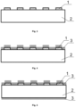
- Optical scales for precise displacement and rotation measurements usually consist of a micrometer-scale reflective metal pattern (1) on a glass substrate (2). Such scales are not resistant to fogging.
- the non-fogging optical scale is a device comprising a known optical scale for the photoelectric encoder, made on the smooth (R q ⁇ 1 nm) glass substrate and protected from fogging by depositing a hydrophilic scratch and wear-resistant DLC film (3) with a thickness of 30 - 350 nm at least on the one side ( Fig. 4 ) and preferably on both sides ( Fig. 5 ) of the scale.
- the preferred thickness of the DLC film on the metal side of the scale is 120 - 200 nm, whereas the preferred thickness of the DLC film on the glass side is 50 - 100 nm.
- the hydrophilic DLC films are deposited on chemically cleaned optical scales by reactive direct current magnetron sputtering of the graphite target using Ar as a sputtering gas, and vapor of the hexamethyldisilane, hexamethyldisiloxane, tetra orthosilicate, or other carbon- and silicon-containing volatile liquid. Films are deposited on the grounded substrate. Negatively biased substrates can also be used. Reactive oxygen gas can be used as an additional source of oxygen. The work pressure during the thin film deposition process is in the range of 10 -3 - 2 ⁇ 10 -2 mbar. In such a way, hydrophilic DLC: SiO x films can be grown.
- the deposition process conditions must be thoroughly optimized because the contact angle of the thin film with water can be varied in the range of 0°-105° using this growth method.
- the larger additional oxygen flows result in the deposition of hydrophilic or even super hydrophilic DLC:SiO x and SiO x films due to the increased O/Si atomic concentration ratio and excessive carbon phase etching.
- the hydrophilicity of the deposited DLC:SiO x and SiO x films can be increased by the oxygen ion beam or plasma post-treatment. In this case, surfaces with a water contact angle ⁇ less than 1° are fabricated.
- the ion beam deposition of the hydrophobic hydrogenated DLC and DLC:SiO x films by an anode layer ion source is used as an alternative technology for non-fogging optical scale fabrication.
- the ion beam energy can be in the 300-1000 eV range.
- the surface roughness of the films (R q ) is in the 0.2-0.6 nm range.
- deposited DLC or DLC:SiO x films are in-situ treated by an oxygen ion beam to make a superhydrophilic surface.
- different ex-situ oxygen plasma treatments such as atmospheric plasma, can be applied for smooth surface fabrication (R q is in the range of 1-2 nm) with water contact angles ⁇ less than 1°.
- hydrophilic DLC films containing nitrogen are deposited on chemically cleaned optical scales by reactive magnetron sputtering of the graphite target using Ar as the sputtering gas and nitrogen as the reactive gas.
- nitrogen ion beam-assisted magnetron sputtering can be used to overcome the drawbacks of reactive magnetron sputtering, such as target poisoning.
- the work pressure during the thin film deposition process is in the 7 ⁇ 10 -4 - 3.3 ⁇ 10 -2 mbar range. These films can contain 10-30 at.% nitrogen. Their contact angle with water can be as low as 30°.
- deposited DLC:N films are in-situ treated by an oxygen ion beam or oxygen plasma to make a superhydrophilic surface with a water contact angle ⁇ less than 1°.
- DLC films are post-treated by UV irradiation.
- a post-treatment can be used for DLC:TiO 2 films.
- DLC:TiO 2 films can be grown using reactive radio frequency current magnetron sputtering of the titanium (Ti) target using Ar as sputtering gas and hydrocarbon gas (e.g., methane, acetylene, propane, butane) or vapor (e.g., pentane, hexane) as a carbon and hydrogen source.
- hydrocarbon gas e.g., methane, acetylene, propane, butane
- vapor e.g., pentane, hexane
- These films can also be deposited by reactive direct current magnetron sputtering or pulsed current magnetron sputtering, or high power impulse magnetron sputtering of the Ti target using Ar as a sputtering gas, hydrocarbon gas as a carbon and hydrogen source, and oxygen gas as an oxygen source. These films can also be deposited by reactive direct current magnetron sputtering or pulsed current magnetron sputtering, or high power impulse magnetron sputtering of the graphite target using metallorganic Ti-containing vapor such as, e.g., titanium isopropoxide as a source of the Ti and O.
- metallorganic Ti-containing vapor such as, e.g., titanium isopropoxide as a source of the Ti and O.
- These films can also be deposited by ICP plasma beam deposition using a hydrocarbon gas or vapor as a carbon source and metallorganic Ti containing vapor such as, e.g., titanium isopropoxide as a source of the Ti and O.
- DLC:TiO 2 films became hydrophilic only after UV treatment.
Landscapes
- Physics & Mathematics (AREA)
- General Physics & Mathematics (AREA)
- Surface Treatment Of Optical Elements (AREA)
- Chemical Vapour Deposition (AREA)
Abstract
Description
- The present invention relates to optical measurements and optical scales for absolute and incremental photoelectric encoders. More specifically, it relates to non-fogging optical scales and scanning reticles protected by hydrophilic diamond-like carbon (DLC) films with excellent scratch and wear resistance and anti-fogging properties.
- Air becomes saturated with water vapor at temperatures below the dew point, and condensation occurs. Water condensation on optically transparent surfaces causes their fogging, resulting in a significantly reduced optical transmittance or distorted optical image behind the fogged surface. The fogging problem is also very relevant for photoelectric encoders, where fogging of scanning reticles and linear or rotary optical scales, consisting of micrometer-scale reflective metallic patterns on the glass substrate, can increase measurement errors or even completely disrupt the operation of the devices.
- The patented designs do not protect against the optical encoder's fogging while ensuring protection from mechanical and chemical impacts.
- The US patent No.
US8739425B2 describes the design of the optical encoder coordinates positioning apparatus. The apparatus comprises a mounting surface, a motion guide that is mountable on the mounting surface, a first member comprising a sensor for sensing scale markings, the first member is mounted on the motion guide, and an encoder scale member comprising a first set of scale markings that are, in use, sensible by the sensor. The sensor may include a transparent window on which a grating may be formed. The surface of the window nearest the scale in use may have a scratch-resistant coating, possibly a DLC coating. - The European patent No.
EP2112477B1 provides a thin metal tape-substrate-based scale for a photoelectric encoder. In that patent, the light-absorption layer having the chemically stable and mechanically durable DLC layer protects the thin metal plate-based substrate from corrosion, rust, and flaws while ensuring the function of the light-absorbing layer. - The US patent application No.
US20060226830A1 describes the magnetic encoder element with the encoding zone protected by a thin layer of DLC deposited by plasma directly on the encoder element. The protective layer significantly increases the ability of the magnetizable polymer surface to withstand abrasion, giving it a long lifetime when the displacement encoder is used in an aggressive environment. The protective layer can also form a barrier against substances that could subject the polymer to chemical attack. - Currently, many different optically transparent, anti-fogging, and mechanical impact-resistant coatings devoted to glass and plastic optical components are on the market (
EP3444641A1 ,EP3508889A1 ,US20180113297A1 ,US11161926B2 US20190324341A1 ,FR3067970B1 CN108717213A ,CN106835043B ,CN109135487B ). However, such coatings have not been used so far for optical scales and reticles. In addition, most of them are polymeric and cannot ensure adequate resistance to scratching and wear. - DLC coatings are more scratch and wear-resistant. The patents described below relate to using advanced hydrophilic DLC coatings, potentially suitable for anti-fogging applications. However, it should be noted that most of these patents focus on the deposition of hydrophilic DLC coatings and do not address fogging issues.
- The US patent No.
US9670092B2 - In the US patent application No.
US20060246218A1 , the hydrophilic DLC surface fabricated by additional post-deposition treatment using barrier discharge pyrolysis, is described. As a result, the oxygen radicals from the plasma cause at least the surface of the DLC inclusive layer to oxidize, which in turn causes its contact angle to drop rapidly in a short period. In certain example embodiments of this invention, a coated article is provided. A coating layer includes both sp2 and sp3 carbon-carbon bonds and has a surface energy of at least about 20 mN/m, more preferably at least about 24 mN/m, and most preferably at least about 26 mN/m. - In the US patent No.
US6303225B1 , the DLC coating was doped with nitrogen (N) and boron (B) to make it more polar and, therefore, more hydrophilic. The optimal ratio of N to B was approximately 2:1 and resulted in a contact angle θ with a drop of water no greater than about 10°. - The US patent No.
US6793979B2 discloses a DLC film doped with at least one polar-inducing dopant (e.g., B, N, and/or any other suitable dopant) to make the layer more hydrophilic. Furthermore, this film can be exposed to ultraviolet (UV) radiation sufficiently to cause the contact angle of the DLC layer to drop into a hydrophilic range (for example, the contact angle θ less than or equal to about 20°). - In the US patent No.
US7455883B2 , the DLC-inclusive coating is treated using flame pyrolysis to cause the coating to become hydrophilic and/or reduce its contact angle. Optionally, the DLC-inclusive coating may also be treated with an ion beam that includes oxygen and/or hot water (e.g., hot water in liquid and/or vapor form). Optionally, polar-inducing dopant(s) (e.g., B, N, P, As, S, Sb, Ga, In, and/or any other polar-inducing dopant) may be provided in the DLC in addition to the ion beam treatment to help the DLC become more polar, which in turn increases surface energy and thus provides for a more hydrophilic coating. In certain optional embodiments, UV treatment can also be used to cause the contact angle θ of the DLC inclusive layer to decrease and/or stay low. - The international patent application No.
WO2014148479A1 describes the hydrophilic DLC film deposited on the surface of a smoothed base material, such as stainless steel, to suppress the adhesion of dirt, such as bacteria, to the surface of the base material. Such a DLC film can be fabricated by various plasma- or ion-based methods. The DLC can be doped with oxygen (O), nitrogen (N), silicon (Si), and silicon oxide (SiOx). The DLC film can also be irradiated with an oxygen plasma or nitrogen plasma so that the surface layer of the amorphous carbon film has a carboxyl group (-COOH), a hydroxyl group (-OH), or the like. In this way, the DLC film is further negatively charged to repel the negatively charged dirt particles. - The Japanese patent No.
JP4704653B2 - The Chinese patent application No.
CN114196937A provides a hydrophilic amorphous carbon film and is related to a preparation technology of a metal coating material. The hydrophilic amorphous carbon film is a Si-containing DLC film. The preparation method involves doping Si atoms in the amorphous carbon film and subsequently activating the film with oxygen plasma or oxygen ion beams. After 48 h of plasma activation, the water contact angle θ of the film was less than 7°. - The Japanese patent No.
JP5706330B2 - The US patent No.
US7033649B2 discloses that a scratch-resistant hydrophilic anti-fogging coating can be manufactured by doping DLC with at least one polar-inducing dopant, such as B and/or N, which increases the graphite-like phase amount in the coating. The polar-inducing dopant's atomic percentage of the polar-inducing dopant(s) should be no greater than 10%. The sp3 type bonds (e.g., C-C bonds) increase the coating hardness and scratch resistance, while the graphitic sp2 type bonds (e.g., C-C, C-N, and/or C-B bonds) cause the coating to be more hydrophilic and have a lower contact angle. The DLC coating may also be exposed to UV radiation to cause the coating to become hydrophilic or more hydrophilic. - The closest prior art to the present invention is the European patent application
EP22212120.4 filed 08.12.2022 EP22212120.4 - Problem. This invention solves the fogging problem of the photoelectric encoders, and thereby enables them to be used near- or below- the dew point temperature, by coating the optical scales and scanning reticles of encoders with transparent hydrophilic DLC films, which also increases the mechanical durability of the coated surfaces.
- Optical scales and reticles for precise displacement and rotation measurements usually consist of micrometer-scale chromium (Cr) gratings on a glass substrate. As the two periodic gratings (scale and reticle) move relative to one another, the incident light is modulated: if the gaps overlap, the light passes, and when the Cr lines of one grating overlap with the gaps of another grating, the light does not pass. Photocells convert light modulation into electric signal modulation. In the case of an open photoelectric encoder, the scanning reticle can be formed on the encoder window.
- One of the problems faced by photoelectric encoder users is the fogging of the optical scale and/or encoder reticle when saturated water vapor condenses into droplets on the transparent surface. These droplets act as optical lenses and, depending on their size, negatively affect the optical transmittance or at least distort the trajectories of optical signals, which can result in measurement errors. The surface of the optical scale or reticle is complex: the glass substrate is naturally hydrophilic with a water contact angle of less than 60°. The Cr pattern has a much higher surface energy, so its water contact angle is close to 90°. The contact angle of the glass can be further reduced by additional surface processing, such as plasma treatment, and it is difficult to change the wettability of the Cr surface. Therefore, the wettability of the complex scale or reticle surface is insufficient for forming a continuous liquid layer, which would ensure high optical transmittance.
- Solution. An optical scale or reticle consisting of Cr or another light reflective metal pattern on the glass substrate can be protected from fogging by depositing a hydrophilic scratch- and wear-resistant DLC film with a thickness of 30 - 350 nm at least on one side and, preferably, on both sides of the scale or reticle. The thickness of the reflective metal pattern usually is about 100 nm. The DLC coating on the metal side of the scale or reticle must be at least 20 nm thicker than the metal pattern to form a continuous film with high surface energy. The maximum coating thickness is limited by internal stresses causing poor substrate adhesion and optical transmittance. Therefore, the preferred thickness of the DLC film on the metal side of the scale or reticle is 120 - 200 nm. The coating may be slightly thinner on the glass side. In this case, the preferred thickness of the DLC film is 50 - 100 nm.
- Non-fogging optical scales or scanning reticles are produced using conventional optical scales or reticles made on a smooth glass substrate (the root mean square roughness of the glass substrate Rq is less than 1 nm) by evaporating Cr or another suitable reflective metal layer and lithographically defining the desired micrometer-scale pattern. The smoothness of the glass surface is crucial to ensure high-quality patterning and low scattering of optical signals. Before the DLC coating, the surface of the optical scales or reticles is cleaned using a wet chemical cleaning process: ultrasonic cleaning in an acetone bath for at least 6 min, followed by ultrasonic cleaning in an isopropyl alcohol bath for at least 3 min, followed by thorough rinsing in deionized (DI) water with a resistivity higher than 18.2 MΩ/cm, and drying in a nitrogen stream. Chemically cleaned optical scales and reticles are immediately coated with transparent hydrophilic DLC.
- The hydrophilic DLC film can be grown by doping the film with N, B, Si, SiOx, or another polar-inducing dopant. Various combinations of the polar dopants mentioned above are also possible. Plasma-enhanced chemical vapor deposition, reactive sputtering, ion beam deposition, cathodic arc evaporation, and pulsed laser deposition can be used for this purpose.
- Another exemplary embodiment is a hydrophilic film deposition by reactive magnetron sputtering of the graphite target using the argon gas, oxygen gas, and hexamethyldisilane vapor mixture. Hexamethyldisiloxane, tetra orthosilicate, and other volatile carbon and silicon-containing liquids can be used instead of hexamethyldisilane. Silicon-containing gases can also be used for this purpose. In such a way, super hydrophilic films can be grown with a water contact angle θ below 10°. In this case, the deposition conditions must be optimized because, in such a way, highly hydrophobic (with a water contact angle above 100°) films can also be deposited. It means that the film composition, such as the amount of the amorphous carbon phase and SiOx phase, must be thoroughly adjusted.
- An alternative way to achieve hydrophilicity is post-treatment of the deposited undoped or doped DLC film by oxygen plasma or oxygen ion beam to create hydrophilic hydroxyl or carboxyl groups on the DLC surface. Another way is DLC post-treatment by UV irradiation. Notably, it can be used for DLC films doped with titanium oxide (DLC: TiO2).
- The main technical effects and advantages of the non-fogging optical scales and scanning reticles made on the smooth glass substrate, according to the present invention, are:
- simplification of surface processing and scale/encoder devices production technology, with respect to the closest prior art (European patent application EP
EP22212120.4 - further, by eliminating the surface roughening step, the quality of lithography is improved, thus ensuring defect-free patterning and reducing the roughness of line edges;
- increasing the resolution of the device;
- reduction of the scattering of optical signals;
- increasing the specular reflection from the metalized surface.
- Possible embodiments of the present invention are described in the accompanying drawings, where:
- Figure 1
- shows a photograph of the optical scale of the photoelectric encoder where reflective metal patterns perform the function of the grating track (1A) and the reference mark zone (1B);
- Figure 2
- shows a photograph of the scanning reticle of the photoelectric encoder consisting of a glass window (1C) and tracks in the form of reflective metal patterns (1D);
- Figure 3
- shows a cross-section of an optical scale, where a reflective metal pattern (1) is formed on one side of the glass substrate (2);
- Figure 4
- shows a cross-section of a non-fogging optical scale coated on one side with a hydrophilic DLC film (3);
- Figure 5
- shows a cross-section of a non-fogging optical scale coated on both sides with a hydrophilic DLC film (3);
- Figure 6
- shows the dependence of the optical transmittance of the silicate glass and the hydrophilic DLC: SiOx coated silicate glass on the water vapor condensation time.
- Abbreviations used in the description:
- DLC - diamond-like carbon;
- N - nitrogen;
- B - boron;
- θ - water contact angle;
- P - phosphorus;
- As - arsenic;
- S - sulphur;
- Sb - antimony;
- Ga - gallium;
- In - indium;
- UV - ultraviolet;
- O - oxygen;
- Si - silicon;
- SiOx - silicon oxide;
- COOH - carboxyl group;
- OH - hydroxyl group;
- DLG - diamond-like glass;
- Si-DLC - Si-containing diamond-like carbon;
- Cr - chromium;
- Rq - surface root mean square (RMS) roughness;
- DLC: N - diamond-like carbon film containing nitrogen;
- Ar - argon;
- TiO2 - titanium oxide;
- Ti - titanium;
- DLC: TiO2 - diamond-like carbon film doped with titanium oxide.
- The present invention relates to solving the fogging problem of optical scales (
Fig. 1 ) and scanning reticles (Fig. 2 ) of photoelectric encoders. In the following description, the term "optical scale" denotes not only the optical scale but also the scanning reticle. - Optical scales for precise displacement and rotation measurements (
Fig. 3 ) usually consist of a micrometer-scale reflective metal pattern (1) on a glass substrate (2). Such scales are not resistant to fogging. According to this invention, the non-fogging optical scale is a device comprising a known optical scale for the photoelectric encoder, made on the smooth (Rq < 1 nm) glass substrate and protected from fogging by depositing a hydrophilic scratch and wear-resistant DLC film (3) with a thickness of 30 - 350 nm at least on the one side (Fig. 4 ) and preferably on both sides (Fig. 5 ) of the scale. The preferred thickness of the DLC film on the metal side of the scale is 120 - 200 nm, whereas the preferred thickness of the DLC film on the glass side is 50 - 100 nm. - Hereinafter, the present invention will be described in more detail based on certain example embodiments of the hydrophilic antifogging DLC films and their deposition techniques. The description of the embodiments includes numerous specific details to provide a complete and comprehensible explanation of the specific features and modifications. However, these embodiments are merely illustrative and do not limit the scope of the invention or restrict the possible applications, which can be implemented without following these specific instructions.
- In some embodiments, the hydrophilic DLC films are deposited on chemically cleaned optical scales by reactive direct current magnetron sputtering of the graphite target using Ar as a sputtering gas, and vapor of the hexamethyldisilane, hexamethyldisiloxane, tetra orthosilicate, or other carbon- and silicon-containing volatile liquid. Films are deposited on the grounded substrate. Negatively biased substrates can also be used. Reactive oxygen gas can be used as an additional source of oxygen. The work pressure during the thin film deposition process is in the range of 10-3 - 2×10⁻² mbar. In such a way, hydrophilic DLC: SiOx films can be grown. The deposition process conditions must be thoroughly optimized because the contact angle of the thin film with water can be varied in the range of 0°-105° using this growth method. The larger additional oxygen flows result in the deposition of hydrophilic or even super hydrophilic DLC:SiOx and SiOx films due to the increased O/Si atomic concentration ratio and excessive carbon phase etching. The hydrophilicity of the deposited DLC:SiOx and SiOx films can be increased by the oxygen ion beam or plasma post-treatment. In this case, surfaces with a water contact angle θ less than 1° are fabricated.
- In some embodiments, the ion beam deposition of the hydrophobic hydrogenated DLC and DLC:SiOx films by an anode layer ion source is used as an alternative technology for non-fogging optical scale fabrication. The ion beam energy can be in the 300-1000 eV range. Acetylene gas, or the mixture of hexamethyldisiloxane vapor and hydrogen gas, respectively, is used as the reagents. The surface roughness of the films (Rq) is in the 0.2-0.6 nm range. Afterward, deposited DLC or DLC:SiOx films are in-situ treated by an oxygen ion beam to make a superhydrophilic surface. Alternatively, different ex-situ oxygen plasma treatments, such as atmospheric plasma, can be applied for smooth surface fabrication (Rq is in the range of 1-2 nm) with water contact angles θ less than 1°.
- In other embodiments, hydrophilic DLC films containing nitrogen (DLC:N; otherwise, amorphous carbon nitride films) are deposited on chemically cleaned optical scales by reactive magnetron sputtering of the graphite target using Ar as the sputtering gas and nitrogen as the reactive gas. Alternatively, nitrogen ion beam-assisted magnetron sputtering can be used to overcome the drawbacks of reactive magnetron sputtering, such as target poisoning. The work pressure during the thin film deposition process is in the 7×10⁻⁴ - 3.3×10⁻² mbar range. These films can contain 10-30 at.% nitrogen. Their contact angle with water can be as low as 30°. Afterward, deposited DLC:N films are in-situ treated by an oxygen ion beam or oxygen plasma to make a superhydrophilic surface with a water contact angle θ less than 1°.
- In further embodiments, DLC films are post-treated by UV irradiation. In particular, such a post-treatment can be used for DLC:TiO2 films. DLC:TiO2 films can be grown using reactive radio frequency current magnetron sputtering of the titanium (Ti) target using Ar as sputtering gas and hydrocarbon gas (e.g., methane, acetylene, propane, butane) or vapor (e.g., pentane, hexane) as a carbon and hydrogen source. These films can also be deposited by reactive direct current magnetron sputtering or pulsed current magnetron sputtering, or high power impulse magnetron sputtering of the Ti target using Ar as a sputtering gas, hydrocarbon gas as a carbon and hydrogen source, and oxygen gas as an oxygen source. These films can also be deposited by reactive direct current magnetron sputtering or pulsed current magnetron sputtering, or high power impulse magnetron sputtering of the graphite target using metallorganic Ti-containing vapor such as, e.g., titanium isopropoxide as a source of the Ti and O. These films can also be deposited by ICP plasma beam deposition using a hydrocarbon gas or vapor as a carbon source and metallorganic Ti containing vapor such as, e.g., titanium isopropoxide as a source of the Ti and O. DLC:TiO2 films became hydrophilic only after UV treatment.
- To illustrate the effectiveness of hydrophilic DLC films for antifogging applications, fogging the hydrogenated DLC:SiOx films deposited by an anode layer ion source on the optically smooth silicate glass substrates and treated by oxygen plasma with a power density of 0.3 W/cm2 for 3 min was investigated. The thickness of the tested DLC films was about 110 nm, and the water contact angle θ after the plasma treatment was less than 1°. Fogging tests were performed by placing uncoated and DLC-coated glasses horizontally in a moisture chamber below the dew point temperature and measuring their optical transmittance at 890 nm over time.
Fig. 6 shows the dependence of the optical transmittance of the silicate glass and the hydrophilic DLC:SiOx coated silicate glass on the water vapor condensation time. It is evident from this figure that the hydrophilic DLC film prevents surface fogging and ensures high optical transmittance of the glass substrate below the dew point.
Claims (14)
- A non-fogging optical scale device for a photoelectric linear or rotary encoder comprising- an optically smooth glass substrate (2) wherein the root-mean-square roughness Rq is less than 1 nm,- a lithographically defined micrometer-scale reflective metal pattern (1) with a thickness of 50-200 nm, and preferably 80-100 nm,- a transparent hydrophilic scratch and wear-resistant diamond-like-carbon DLC film (3) with a thickness of 30-350 nm grown at least on one surface, and preferably on both surfaces of the scale.
- The device, according to claim 1, wherein the thickness of the DLC film on the metal side of the scale (1) is 120-200 nm, and on the glass side (2) is 50-100 nm.
- The device, according to claims 1 and 2, wherein the DLC film further comprises any diamond-like-carbon atoms, graphite-like carbon atoms, hydrogen atoms, or any of the doped N, B, Si, SiOx, TiO2 or other polar impurities, for an increase in the hydrophilicity of the surface.
- A non-fogging scanning reticle device for photoelectric linear or rotary encoder with the features specified in claims 1 to 3.
- A non-fogging window with an integrated scanning reticle device for an open photoelectric encoder with the features specified in claims 1 to 3.
- A method of fabricating the non-fogging optical scale, non-fogging scanning reticle, and non-fogging window with integrated scanning reticle devices according to any of claims 1 to 5, the method comprising steps ofa) surface preparation:• ultrasonic cleaning in an acetone bath for at least 6 min, followed by• ultrasonic cleaning in an isopropyl alcohol bath for at least 3 min, followed by• thorough rinsing in deionized water with a resistivity higher than 18.2 MΩ/cm, and• drying in a nitrogen stream,b) depositing a transparent hydrophilic scratch and wear-resistant DLC film on at least one side, and preferably both sides of the device.
- The method of claim 6, wherein during step b), a hydrophilic DLC film doped with N, B, Si, SiOx, or other polar-inducing dopants, or various combinations of polar dopants is grown by plasma-enhanced chemical vapor deposition, reactive sputtering, ion beam deposition, cathodic arc evaporation, and pulsed laser deposition.
- The method of claim 6, wherein during the step b), the hydrophilic DLC film is deposited by reactive magnetron sputtering of the graphite target using the mixture of argon gas, oxygen gas, and hexamethyldisilane vapor (hexamethyldisiloxane or tetra orthosilicate, or other volatile liquid containing carbon and silicon, or a silicon-containing gas may be used instead of hexamethyldisilane).
- The method of claim 6, wherein the deposited undoped or doped DLC film is post-treated by an oxygen plasma or an oxygen ion beam.
- The method of claim 6, wherein during step b) the hydrogenated DLC film is deposited by an anode layer ion source using acetylene gas or the DLC:SiOx film is deposited by an anode layer ion source using the mixture of hexamethyldisiloxane vapor and hydrogen gas, and it is post-treated by an oxygen plasma or oxygen ion beam.
- The method of claim 6, wherein during step b) the hydrophilic DLC:N film is deposited by reactive magnetron sputtering of the graphite target using Ar as the sputtering gas and nitrogen as the reactive gas, or the hydrophilic DLC:N film is deposited by nitrogen ion beam assisted magnetron sputtering, and it is treated in situ by an oxygen ion beam or an oxygen plasma.
- The method of claim 6, wherein during step b) the DLC:TiO2 film is grown by reactive radio frequency current magnetron sputtering or reactive direct current magnetron sputtering or pulsed current magnetron sputtering or high power impulse magnetron sputtering of the Ti target using Ar as the sputtering gas, hydrocarbon gas (e.g. methane, acetylene, propane, butane) or vapor (e.g. pentane, hexane) as a carbon and hydrogen source and oxygen gas as an oxygen source, and it is post-treated by UV irradiation.
- The method of claim 6, wherein during step b) the DLC:TiO2 film is deposited by ICP plasma or reactive direct current magnetron sputtering or pulsed current magnetron sputtering or high power impulse magnetron sputtering of the graphite target using metallorganic Ti containing vapor such as, e.g., titanium isopropoxide as a source of the Ti and O, and it is post-treated by UV irradiation.
- A photoelectric encoder comprising non-fogging optical scales or non-fogging scanning reticles, or non-fogging windows with integrated scanning reticles according to claims 1 to 5.
Priority Applications (1)
| Application Number | Priority Date | Filing Date | Title |
|---|---|---|---|
| EP23171887.5A EP4459237B1 (en) | 2023-05-05 | 2023-05-05 | Non-fogging optical scales and scanning reticles coated by hydrophilic diamond-like carbon films |
Applications Claiming Priority (1)
| Application Number | Priority Date | Filing Date | Title |
|---|---|---|---|
| EP23171887.5A EP4459237B1 (en) | 2023-05-05 | 2023-05-05 | Non-fogging optical scales and scanning reticles coated by hydrophilic diamond-like carbon films |
Publications (3)
| Publication Number | Publication Date |
|---|---|
| EP4459237A1 true EP4459237A1 (en) | 2024-11-06 |
| EP4459237B1 EP4459237B1 (en) | 2026-01-21 |
| EP4459237C0 EP4459237C0 (en) | 2026-01-21 |
Family
ID=86330200
Family Applications (1)
| Application Number | Title | Priority Date | Filing Date |
|---|---|---|---|
| EP23171887.5A Active EP4459237B1 (en) | 2023-05-05 | 2023-05-05 | Non-fogging optical scales and scanning reticles coated by hydrophilic diamond-like carbon films |
Country Status (1)
| Country | Link |
|---|---|
| EP (1) | EP4459237B1 (en) |
Citations (24)
| Publication number | Priority date | Publication date | Assignee | Title |
|---|---|---|---|---|
| US6303225B1 (en) | 2000-05-24 | 2001-10-16 | Guardian Industries Corporation | Hydrophilic coating including DLC on substrate |
| DE10056605A1 (en) * | 2000-11-15 | 2002-05-23 | Kostal Leopold Gmbh & Co Kg | Method for signal evaluation of an opto-electronic path or angle measurement device, especially for determination of a vehicle steering column position, in which adjustments can be made for impaired sensors or damaged code wheel |
| US6793979B2 (en) | 2000-05-24 | 2004-09-21 | Guardian Industries Corp. | Hydrophilic DLC on substrate with UV exposure |
| US20060226830A1 (en) | 2005-04-11 | 2006-10-12 | Hutchinson | Encoder for a movable shaft, a device including such an encoder, and a method of fabricating such an encoder |
| US20060246218A1 (en) | 2005-04-29 | 2006-11-02 | Guardian Industries Corp. | Hydrophilic DLC on substrate with barrier discharge pyrolysis treatment |
| US7455883B2 (en) | 2004-10-19 | 2008-11-25 | Guardian Industries Corp. | Hydrophilic DLC on substrate with flame pyrolysis treatment |
| JP4704653B2 (en) | 2000-03-05 | 2011-06-15 | スリーエム イノベイティブ プロパティズ カンパニー | Fluid treatment apparatus having diamond-like film |
| US20130344290A1 (en) * | 2011-03-14 | 2013-12-26 | 3M Innovative Properties Company | Nanostructured articles |
| US8739425B2 (en) | 2009-02-16 | 2014-06-03 | Renishaw Plc | Encoder scale member and method for mounting |
| WO2014148479A1 (en) | 2013-03-19 | 2014-09-25 | 太陽化学工業株式会社 | Structure provided with antifouling amorphous carbon film and method for forming antifouling amorphous carbon film |
| EP2112477B1 (en) | 2008-04-25 | 2014-10-22 | Mitutoyo Corporation | Scale for photoelectric encoder |
| JP5706330B2 (en) | 2009-10-08 | 2015-04-22 | コリア・インスティテュート・オブ・サイエンス・アンド・テクノロジー | Silicon-containing diamond-like carbon thin film, method for producing the same, and use thereof |
| US9670092B2 (en) | 2010-02-26 | 2017-06-06 | Guardian Industries Corp. | Articles including anticondensation and/or low-E coatings and/or methods of making the same |
| CN106835043A (en) | 2017-02-03 | 2017-06-13 | 国家纳米科学中心 | A kind of transparent hydrophobic film, Preparation Method And The Use |
| US20180113297A1 (en) | 2016-10-21 | 2018-04-26 | Tanner Research, Inc. | Active droplet transport defogging |
| CN108717213A (en) | 2018-03-10 | 2018-10-30 | 曹伟 | Increase the method for hydrophily anti-fog coating and hydrophily self-cleaning coat, hydrophobicity self-cleaning coat case hardness |
| CN109135487A (en) | 2018-07-19 | 2019-01-04 | 重庆大学 | Super hydrophilic anti-fog coating of organosilicon modified crylic acid resin and preparation method thereof |
| EP3444641A1 (en) | 2017-08-16 | 2019-02-20 | Honeywell International Inc. | Anti-fog and anti-reflective dual-functional coating for optical articles |
| EP3508889A1 (en) | 2018-01-09 | 2019-07-10 | Danmarks Tekniske Universitet | Anti-fogging transparent surface |
| US20190324341A1 (en) | 2018-04-19 | 2019-10-24 | Gentex Corporation | Plastic coatings for improved solvent resistance |
| FR3067970B1 (en) | 2017-06-27 | 2020-12-11 | Valeo Vision | ANTI-CONDENSATION COATING FOR OPTICAL ELEMENT |
| US11161926B2 (en) | 2018-01-15 | 2021-11-02 | University Of Georgia Research Foundation, Inc. | Surfaces having antifogging characteristics, coating compositions having antifogging characteristics, and methods of making antifogging surfaces |
| JP2021192008A (en) * | 2020-06-05 | 2021-12-16 | 株式会社ミツトヨ | Scale and manufacturing method of the same |
| CN114196937A (en) | 2021-12-16 | 2022-03-18 | 浙江大学杭州国际科创中心 | Hydrophilic amorphous carbon film and preparation method thereof |
-
2023
- 2023-05-05 EP EP23171887.5A patent/EP4459237B1/en active Active
Patent Citations (25)
| Publication number | Priority date | Publication date | Assignee | Title |
|---|---|---|---|---|
| JP4704653B2 (en) | 2000-03-05 | 2011-06-15 | スリーエム イノベイティブ プロパティズ カンパニー | Fluid treatment apparatus having diamond-like film |
| US6793979B2 (en) | 2000-05-24 | 2004-09-21 | Guardian Industries Corp. | Hydrophilic DLC on substrate with UV exposure |
| US7033649B2 (en) | 2000-05-24 | 2006-04-25 | Guardian Industries Corp. | Hydrophilic DLC on substrate with UV exposure |
| US6303225B1 (en) | 2000-05-24 | 2001-10-16 | Guardian Industries Corporation | Hydrophilic coating including DLC on substrate |
| DE10056605A1 (en) * | 2000-11-15 | 2002-05-23 | Kostal Leopold Gmbh & Co Kg | Method for signal evaluation of an opto-electronic path or angle measurement device, especially for determination of a vehicle steering column position, in which adjustments can be made for impaired sensors or damaged code wheel |
| US7455883B2 (en) | 2004-10-19 | 2008-11-25 | Guardian Industries Corp. | Hydrophilic DLC on substrate with flame pyrolysis treatment |
| US20060226830A1 (en) | 2005-04-11 | 2006-10-12 | Hutchinson | Encoder for a movable shaft, a device including such an encoder, and a method of fabricating such an encoder |
| US20060246218A1 (en) | 2005-04-29 | 2006-11-02 | Guardian Industries Corp. | Hydrophilic DLC on substrate with barrier discharge pyrolysis treatment |
| EP2112477B1 (en) | 2008-04-25 | 2014-10-22 | Mitutoyo Corporation | Scale for photoelectric encoder |
| US8739425B2 (en) | 2009-02-16 | 2014-06-03 | Renishaw Plc | Encoder scale member and method for mounting |
| JP5706330B2 (en) | 2009-10-08 | 2015-04-22 | コリア・インスティテュート・オブ・サイエンス・アンド・テクノロジー | Silicon-containing diamond-like carbon thin film, method for producing the same, and use thereof |
| US9670092B2 (en) | 2010-02-26 | 2017-06-06 | Guardian Industries Corp. | Articles including anticondensation and/or low-E coatings and/or methods of making the same |
| US20130344290A1 (en) * | 2011-03-14 | 2013-12-26 | 3M Innovative Properties Company | Nanostructured articles |
| WO2014148479A1 (en) | 2013-03-19 | 2014-09-25 | 太陽化学工業株式会社 | Structure provided with antifouling amorphous carbon film and method for forming antifouling amorphous carbon film |
| US20180113297A1 (en) | 2016-10-21 | 2018-04-26 | Tanner Research, Inc. | Active droplet transport defogging |
| CN106835043A (en) | 2017-02-03 | 2017-06-13 | 国家纳米科学中心 | A kind of transparent hydrophobic film, Preparation Method And The Use |
| FR3067970B1 (en) | 2017-06-27 | 2020-12-11 | Valeo Vision | ANTI-CONDENSATION COATING FOR OPTICAL ELEMENT |
| EP3444641A1 (en) | 2017-08-16 | 2019-02-20 | Honeywell International Inc. | Anti-fog and anti-reflective dual-functional coating for optical articles |
| EP3508889A1 (en) | 2018-01-09 | 2019-07-10 | Danmarks Tekniske Universitet | Anti-fogging transparent surface |
| US11161926B2 (en) | 2018-01-15 | 2021-11-02 | University Of Georgia Research Foundation, Inc. | Surfaces having antifogging characteristics, coating compositions having antifogging characteristics, and methods of making antifogging surfaces |
| CN108717213A (en) | 2018-03-10 | 2018-10-30 | 曹伟 | Increase the method for hydrophily anti-fog coating and hydrophily self-cleaning coat, hydrophobicity self-cleaning coat case hardness |
| US20190324341A1 (en) | 2018-04-19 | 2019-10-24 | Gentex Corporation | Plastic coatings for improved solvent resistance |
| CN109135487A (en) | 2018-07-19 | 2019-01-04 | 重庆大学 | Super hydrophilic anti-fog coating of organosilicon modified crylic acid resin and preparation method thereof |
| JP2021192008A (en) * | 2020-06-05 | 2021-12-16 | 株式会社ミツトヨ | Scale and manufacturing method of the same |
| CN114196937A (en) | 2021-12-16 | 2022-03-18 | 浙江大学杭州国际科创中心 | Hydrophilic amorphous carbon film and preparation method thereof |
Also Published As
| Publication number | Publication date |
|---|---|
| EP4459237B1 (en) | 2026-01-21 |
| EP4459237C0 (en) | 2026-01-21 |
Similar Documents
| Publication | Publication Date | Title |
|---|---|---|
| US6303225B1 (en) | Hydrophilic coating including DLC on substrate | |
| Takikawa et al. | Properties of titanium oxide film prepared by reactive cathodic vacuum arc deposition | |
| Santos et al. | Modified stainless steel surfaces targeted to reduce fouling––surface characterization | |
| CN1946646B (en) | Substrates, especially glass substrates, with hydrophobic surfaces and improved durability of hydrophobic properties | |
| CA2466488C (en) | Hydrophilic dlc on substrate with uv exposure | |
| Neuville | New application perspective for tetrahedral amorphous carbon coatings | |
| WO2004033383A1 (en) | Hydrophilic dlc on substrate with ion beam treatment | |
| US20160326048A1 (en) | Low reflective and superhydrophobic or super water-repellent glasses and method of fabricating the same | |
| JP3904355B2 (en) | Hydrophilic photocatalytic member | |
| WO2020164735A1 (en) | Functional coated article | |
| EP4459237B1 (en) | Non-fogging optical scales and scanning reticles coated by hydrophilic diamond-like carbon films | |
| JP3128554B2 (en) | Method for forming oxide optical thin film and apparatus for forming oxide optical thin film | |
| WO2021261225A1 (en) | Hydrophilic film manufacturing method, hydrophilic film, and optical member | |
| Hu et al. | Effects of the chemical bonding on the optical and mechanical properties for germanium carbide films used as antireflection and protection coating of ZnS windows | |
| Tran et al. | Role of the surface chemistry of plasma polymer layers on their long‐term antifogging behavior | |
| CA2583940C (en) | Hydrophilic dlc on substrate with flame pyrolysis treatment | |
| US20070178301A1 (en) | Antisoiling dlc layer | |
| Grigaliūnas et al. | Anti-fogging technique for protection of optical grating scales | |
| US20100068529A1 (en) | Films containing an infused oxygenated as and methods for their preparation | |
| Petrmichl et al. | Diamond-Like Carbon as a protective coating for decorative glass | |
| Aïssa et al. | Anti-Reflection and Dust-Repellant Silica Coatings with Tailored Mechanical and Optical Properties for Desert Conditions | |
| KR20240152906A (en) | Thin film containing silicon and oxygen | |
| Macleod | Overview of coating techniques | |
| Caneve et al. | Influence of deposition parameters on rf-sputtered DLC thin films | |
| Taga | Modification of optical properties of transparent substrates by physical vapor deposition |
Legal Events
| Date | Code | Title | Description |
|---|---|---|---|
| PUAI | Public reference made under article 153(3) epc to a published international application that has entered the european phase |
Free format text: ORIGINAL CODE: 0009012 |
|
| STAA | Information on the status of an ep patent application or granted ep patent |
Free format text: STATUS: REQUEST FOR EXAMINATION WAS MADE |
|
| 17P | Request for examination filed |
Effective date: 20240926 |
|
| AK | Designated contracting states |
Kind code of ref document: A1 Designated state(s): AL AT BE BG CH CY CZ DE DK EE ES FI FR GB GR HR HU IE IS IT LI LT LU LV MC ME MK MT NL NO PL PT RO RS SE SI SK SM TR |
|
| GRAP | Despatch of communication of intention to grant a patent |
Free format text: ORIGINAL CODE: EPIDOSNIGR1 |
|
| STAA | Information on the status of an ep patent application or granted ep patent |
Free format text: STATUS: GRANT OF PATENT IS INTENDED |
|
| INTG | Intention to grant announced |
Effective date: 20250922 |
|
| RIC1 | Information provided on ipc code assigned before grant |
Ipc: G01D 5/347 20060101AFI20250912BHEP |
|
| GRAS | Grant fee paid |
Free format text: ORIGINAL CODE: EPIDOSNIGR3 |
|
| GRAA | (expected) grant |
Free format text: ORIGINAL CODE: 0009210 |
|
| STAA | Information on the status of an ep patent application or granted ep patent |
Free format text: STATUS: THE PATENT HAS BEEN GRANTED |
|
| AK | Designated contracting states |
Kind code of ref document: B1 Designated state(s): AL AT BE BG CH CY CZ DE DK EE ES FI FR GB GR HR HU IE IS IT LI LT LU LV MC ME MK MT NL NO PL PT RO RS SE SI SK SM TR |
|
| REG | Reference to a national code |
Ref country code: CH Ref legal event code: F10 Free format text: ST27 STATUS EVENT CODE: U-0-0-F10-F00 (AS PROVIDED BY THE NATIONAL OFFICE) Effective date: 20260121 |
|
| REG | Reference to a national code |
Ref country code: DE Ref legal event code: R096 Ref document number: 602023010893 Country of ref document: DE |
|
| REG | Reference to a national code |
Ref country code: IE Ref legal event code: FG4D |
|
| U01 | Request for unitary effect filed |
Effective date: 20260129 |
|
| U07 | Unitary effect registered |
Designated state(s): AT BE BG DE DK EE FI FR IT LT LU LV MT NL PT RO SE SI Effective date: 20260204 |
|
| U20 | Renewal fee for the european patent with unitary effect paid |
Year of fee payment: 4 Effective date: 20260525 |
|
| PG25 | Lapsed in a contracting state [announced via postgrant information from national office to epo] |
Ref country code: RS Free format text: LAPSE BECAUSE OF FAILURE TO SUBMIT A TRANSLATION OF THE DESCRIPTION OR TO PAY THE FEE WITHIN THE PRESCRIBED TIME-LIMIT Effective date: 20260421 |
|
| PG25 | Lapsed in a contracting state [announced via postgrant information from national office to epo] |
Ref country code: ES Free format text: LAPSE BECAUSE OF FAILURE TO SUBMIT A TRANSLATION OF THE DESCRIPTION OR TO PAY THE FEE WITHIN THE PRESCRIBED TIME-LIMIT Effective date: 20260121 |
|
| PG25 | Lapsed in a contracting state [announced via postgrant information from national office to epo] |
Ref country code: PL Free format text: LAPSE BECAUSE OF FAILURE TO SUBMIT A TRANSLATION OF THE DESCRIPTION OR TO PAY THE FEE WITHIN THE PRESCRIBED TIME-LIMIT Effective date: 20260121 |
|
| PG25 | Lapsed in a contracting state [announced via postgrant information from national office to epo] |
Ref country code: GR Free format text: LAPSE BECAUSE OF FAILURE TO SUBMIT A TRANSLATION OF THE DESCRIPTION OR TO PAY THE FEE WITHIN THE PRESCRIBED TIME-LIMIT Effective date: 20260422 |
|
| PG25 | Lapsed in a contracting state [announced via postgrant information from national office to epo] |
Ref country code: NO Free format text: LAPSE BECAUSE OF FAILURE TO SUBMIT A TRANSLATION OF THE DESCRIPTION OR TO PAY THE FEE WITHIN THE PRESCRIBED TIME-LIMIT Effective date: 20260421 |
|
| PG25 | Lapsed in a contracting state [announced via postgrant information from national office to epo] |
Ref country code: HR Free format text: LAPSE BECAUSE OF FAILURE TO SUBMIT A TRANSLATION OF THE DESCRIPTION OR TO PAY THE FEE WITHIN THE PRESCRIBED TIME-LIMIT Effective date: 20260121 |
|
| PG25 | Lapsed in a contracting state [announced via postgrant information from national office to epo] |
Ref country code: IS Free format text: LAPSE BECAUSE OF FAILURE TO SUBMIT A TRANSLATION OF THE DESCRIPTION OR TO PAY THE FEE WITHIN THE PRESCRIBED TIME-LIMIT Effective date: 20260521 |