EP4459196A1 - Base unit for a heat pump - Google Patents
Base unit for a heat pump Download PDFInfo
- Publication number
- EP4459196A1 EP4459196A1 EP23171786.9A EP23171786A EP4459196A1 EP 4459196 A1 EP4459196 A1 EP 4459196A1 EP 23171786 A EP23171786 A EP 23171786A EP 4459196 A1 EP4459196 A1 EP 4459196A1
- Authority
- EP
- European Patent Office
- Prior art keywords
- heat pump
- base unit
- lifting
- unit
- base
- Prior art date
- Legal status (The legal status is an assumption and is not a legal conclusion. Google has not performed a legal analysis and makes no representation as to the accuracy of the status listed.)
- Withdrawn
Links
Images


Classifications
-
- F—MECHANICAL ENGINEERING; LIGHTING; HEATING; WEAPONS; BLASTING
- F24—HEATING; RANGES; VENTILATING
- F24F—AIR-CONDITIONING; AIR-HUMIDIFICATION; VENTILATION; USE OF AIR CURRENTS FOR SCREENING
- F24F1/00—Room units for air-conditioning, e.g. separate or self-contained units or units receiving primary air from a central station
- F24F1/06—Separate outdoor units, e.g. outdoor unit to be linked to a separate room comprising a compressor and a heat exchanger
- F24F1/46—Component arrangements in separate outdoor units
-
- F—MECHANICAL ENGINEERING; LIGHTING; HEATING; WEAPONS; BLASTING
- F24—HEATING; RANGES; VENTILATING
- F24F—AIR-CONDITIONING; AIR-HUMIDIFICATION; VENTILATION; USE OF AIR CURRENTS FOR SCREENING
- F24F1/00—Room units for air-conditioning, e.g. separate or self-contained units or units receiving primary air from a central station
- F24F1/06—Separate outdoor units, e.g. outdoor unit to be linked to a separate room comprising a compressor and a heat exchanger
- F24F1/08—Compressors specially adapted for separate outdoor units
- F24F1/10—Arrangement or mounting thereof
-
- F—MECHANICAL ENGINEERING; LIGHTING; HEATING; WEAPONS; BLASTING
- F24—HEATING; RANGES; VENTILATING
- F24F—AIR-CONDITIONING; AIR-HUMIDIFICATION; VENTILATION; USE OF AIR CURRENTS FOR SCREENING
- F24F1/00—Room units for air-conditioning, e.g. separate or self-contained units or units receiving primary air from a central station
- F24F1/06—Separate outdoor units, e.g. outdoor unit to be linked to a separate room comprising a compressor and a heat exchanger
- F24F1/14—Heat exchangers specially adapted for separate outdoor units
- F24F1/16—Arrangement or mounting thereof
-
- F—MECHANICAL ENGINEERING; LIGHTING; HEATING; WEAPONS; BLASTING
- F24—HEATING; RANGES; VENTILATING
- F24F—AIR-CONDITIONING; AIR-HUMIDIFICATION; VENTILATION; USE OF AIR CURRENTS FOR SCREENING
- F24F1/00—Room units for air-conditioning, e.g. separate or self-contained units or units receiving primary air from a central station
- F24F1/06—Separate outdoor units, e.g. outdoor unit to be linked to a separate room comprising a compressor and a heat exchanger
- F24F1/56—Casing or covers of separate outdoor units, e.g. fan guards
-
- F—MECHANICAL ENGINEERING; LIGHTING; HEATING; WEAPONS; BLASTING
- F24—HEATING; RANGES; VENTILATING
- F24F—AIR-CONDITIONING; AIR-HUMIDIFICATION; VENTILATION; USE OF AIR CURRENTS FOR SCREENING
- F24F1/00—Room units for air-conditioning, e.g. separate or self-contained units or units receiving primary air from a central station
- F24F1/06—Separate outdoor units, e.g. outdoor unit to be linked to a separate room comprising a compressor and a heat exchanger
- F24F1/60—Arrangement or mounting of the outdoor unit
-
- F—MECHANICAL ENGINEERING; LIGHTING; HEATING; WEAPONS; BLASTING
- F24—HEATING; RANGES; VENTILATING
- F24F—AIR-CONDITIONING; AIR-HUMIDIFICATION; VENTILATION; USE OF AIR CURRENTS FOR SCREENING
- F24F2221/00—Details or features not otherwise provided for
- F24F2221/36—Modules, e.g. for an easy mounting or transport
Definitions
- the invention relates to a base unit for placement in a heat pump unit.
- the invention further relates to a heat pump unit comprising such a base unit and a method of assembling, disassembling or maintaining such a heat pump unit.
- Heat pump units are widely used for heating and cooling purposes.
- Heat pump units comprise a variety of components.
- air-source heat pump units have at least one refrigeration circuit comprising a compressor, a water/refrigerant heat exchanger, an expansion valve and an air/refrigerant heat exchanger.
- Heat pump units comprise a housing, formed by a base plate and a plurality of panels (side panels, top panel) creating an inner space in which several heat pump components are placed.
- components are usually directly assembled to the base plate of the heat pump before any panels are present.
- the base plate is usually flat.
- the heat pump components are gradually positioned and connected. Some heat pump components are directly fixed to the based plate using screws, rivets, brazing, ties etc. Other heat pump components may be fixed to the base plate indirectly, i.e. via one or more other heat pump components.
- One example is the compressor, which may be fixed to an intermediate and independent plate resting on anti-vibration pads. The anti-vibration pads are connected to the base plate. This solution allows the compressor and the vibrations generated during its operation to be decoupled from the rest of the heat pump unit in a more efficient manner.
- heat pump components like structure, air ducting, casing, electrical connections etc. are then assembled around and on top of this assembly of a base plate with heat pump components connected to the base plate.
- the side and top panels are provided and attached to finish the heat pump unit.
- Access to some heat pump components once the product is installed may be difficult or impossible, making maintenance more difficult. Indeed, some components may cover or block access or view of other heat pump components. This makes maintenance of the heat pump unit time consuming, as it requires removing one or more side panels to get access to some heat pump components.
- the manufacturing and assembly process imposes constraints on the production line, in particular through the integration of long and non-dissociable tasks such as the brazing of the heat pump components. These constraints can lead to a bottleneck in the production line and therefore lead to additional assembly time and production cost.
- the object of the invention is to provide an improved manner of assembling and maintaining a heat pump unit.
- the object is solved by providing a base unit for placement in a heat pump unit, wherein the base unit comprises a frame and a plurality of heat pump components, the heat pump components being attached to the frame wherein the base unit comprises at least one lifting point.
- the heat pump components may be directly attached to the frame or may be attached to another component which is directly or indirectly attached to the frame, such that they can be lifted together with the frame.
- the lifting point is advantageously provided on the frame.
- the lifting point may also be provided on one or more of the heat pump components attached to the frame.
- Assembly and maintenance are improved by providing a base unit with attached heat pump components.
- This allows insertion and removal of the base unit as a functional block in and out of the heat pump unit.
- the base unit can be inserted into a (nearly) finished heat pump housing or casing. This allows certain modularity, as one can have most heat pump components on the base unit, where that base unit may be assembled on a different production line.
- the base unit can be taken out as a whole for maintenance without having to open all panels or removing, for instance, the fan. By having a lifting point at the base unit placing and replacing the base unit as a whole is facilitated.
- the provided solution offers more options for assembly by allowing tasks to be carried out outside the heat pump unit by disassembling and removing the base unit. This allows better access to all components and greatly improved ergonomics. The fact of having a better access also makes it possible to improve the soldering and to avoid leaks associated with a bad soldering (bad access, bad visibility etc).
- the base unit also makes it possible to dissociate the production of the base unit from the production of the rest of the heat pump unit, such as the structure and the housing on a production line. This offers greater production flexibility and thus the ability to produce a wider range of products that are more accurately adapted to consumer needs (delayed customization).
- This solution improves the ergonomics of the users (fitters, repairers, recyclers) and their safety by allowing the base unit to be carried by a lifting device. Indeed, this type of base unit generally weighs at least 15 kg.
- this design also allows for easy replacement of the entire base unit. Replacing the base unit allows for easy transport and ensures that the base unit meets industry requirements. The failed base unit can also be easily shipped back to the manufacturer for analysis of the cause of the failure and reconditioning of the base unit.
- the provision of the base unit also reduces the risk of bad assembly that happens when an installer changes a heat pump unit component directly in the heat pump unit.
- the bad assembly can result from bad access and/or visibility and/or not have an ergonomic position when doing maintenance in the heat pump unit.
- the frame is made of metal and/or plastic.
- the frame is preferably made of sheet metal, in particular folded sheet metal.
- the frame comprises a bottom plate.
- One or more of the heat pump components may be positioned on the bottom plate
- the bottom plate can carry several heat pump components.
- the bottom plate can be easily placed and fixed inside a heat pump unit, i.e. in the housing of a heat pump unit.
- the bottom plate can have a shape and the heat pump unit can have a corresponding countershape for facilitating fixing the components to each other.
- the frame comprises one or more lifting plates attached to the bottom plate, each lifting plate comprising one or more lifting points.
- Lifting plate may perpendicularly connected on the bottom plate, or with a small angle deviating from perpendicular ( ⁇ 5°).
- the lifting points can be provided in an accessible manner and above the centre of gravity of the base unit, in particular the centre of gravity of the frame and the heat pump components arranged on the frame, respectively. Such positioning of the lifting points provides stability when lifted and prevents the whole assembly from tipping over.
- “Above” refers to gravity direction.
- At least one heat pump unit component is attached to the bottom plate and at least one other heat pump unit component is attached to the lifting plate.
- Whether the heat pump unit component is attached to the bottom plate or to the lifting plate can depend on one more factors, like reliability, feasability or compacity.
- a compressor can be fixed on the horizontal bottom plate because it is the only fixing points of the compressor and it needs to stay vertical when running.
- a plate heat exchanger, a bottle, a pipe, a pump etc. can be installed vertically and does not need to rest on the bottom so it is more compact to install it on a vertical plane such as the lifting plate.
- the compressor is attached to the bottom plate and a, in particular plate, heat exchanger is fixed to the lifting plate.
- a, in particular plate, heat exchanger is fixed to the lifting plate.
- the heat pump unit is a monobloc heat pump to heat and/or cool water.
- the lifting point can be arranged in the lifting plate and/or in the heat pump component unit attached to the frame of the base unit.
- the frame comprises a lifting plate which is attached to a section of the bottom plate.
- the location of the section of the bottom plate depends on the positon of the center of gravity of the base unit.
- the lifting plate can be arranged such that the centre of gravity is arranged within the lifting plate or is arranged within a predetermined range adjacent to the lifting plate.
- the centre of gravity can be arranged adjacent to the lifting portion in a direction perpendicular to a lifting plate and/or gravity direction.
- the bottom plate may be a rectangular plate having a width and a length.
- the lifting plate may have at least one outer edge having a length substantially equal to the width of the bottom plate, which outer edge is attached to the bottom plate parallel to the width.
- a first heat pump component is positioned on a first side of the base unit and a second heat pump component is positioned on a second side of the base unit, the second side being separated by the lifting late from the first side and being opposite of the first side.
- the two sides are arranged opposite to each other referring to the lifting plate.
- the first heat pump component can be a compressor and the at least one second heat pump component can be a heat exchanger or a refrigerant pipe or a liquid receiver or a hydraulic pipe or a pump.
- heat exchanger a monobloc heat pump unit can be provided.
- the frame comprises two lifting plates the frame being U-shaped, the bottom plate forming the base of the U-shape and the two lifting plates forming the legs of the U-shape.
- the bottom plate may be rectangular or square shaped, with a first lifting plate being attached along a first edge of the bottom plate and a second lifting plate being attached along a second edge of the bottom plate, the first and second edge of the bottom plate being opposite each other.
- each lifting plate has one or more lifting points, the base unit can be lifted in a stable and balanced manner.
- the heat pump components are configured to carry a refrigerant, the heat pump components being selected from at least one of an expansion valve, a, in particular plate, heat exchanger, a liquid receiver and a compressor.
- a liquid receiver is a component by means of which a refrigerant is stored, wherein the stored refrigerant is the refrigerant that is not necessary in a heating operation mode of the heat pump unit or in the cooling operation mode of the heat pump.
- the heat exchanger may be a first heat exchanger, being a destination medium/refrigerant heat exchanger.
- the destination medium is the medium to be heated or cooled by the heat pump unit.
- the destination medium may be water.
- the refrigerant may be propane (R290), R32, R1234yf, R1234ze, R744 (CO 2 ), R452B or R410.
- the heat pump components configured to carry a refrigerant attached to the frame may comprise a second heat exchanger, being a source medium/refrigerant heat exchanger.
- the source medium is the medium from which heat or cold is used by the heat pump unit to heat or cool the destination medium.
- the source medium may be air or water.
- the destination medium can be water or brine and/or can circulate in a closed loop.
- the heat pump components configured to carry a refrigerant attached to the frame may comprise refrigerant piping connecting the expansion valve, compressor and at least one heat exchanger to form (part of) a refrigeration circuit.
- the base unit comprises further heat pump components being selected at least one from a pump, a filter, a probe, a cylinder, a sensor, a hydraulic connection, an air vent and a flow meter.
- the hydraulic connection can be a hydraulic pipe.
- the lifting points are provided by holes, configured to receive a hook, a pin or a carabiner.
- the base unit comprises a single lifting point located in a predetermined range around the center of gravity, in particular above the center of gravity, of the base unit, or two or more lifting points each of which located in a predetermined range around the center of gravity, in particular above the center of gravity, of the base unit.
- each of the lifting points does not need to be located at the centre of gravity in a horizontal direction. Only the barycentre of these lifting holes need to be positioned above the center of gravity. In a vertical direction the lifting points have to be higher than the center of gravity of the assembly.
- a heat pump unit comprising a housing, the housing comprising a heat pump unit base plate and a plurality of panels connected to the heat pump unit base plate, the heat pump unit further comprising a base unit according to any one of the preceding claims, wherein the base unit is positioned on the base plate.
- the base unit can be directly or indirectly positioned on the base plate.
- the base unit may be positioned directly on the base plate or indirectly, as interface parts such as anti-vibration pads may be provided in between the base unit and the base plate.
- the interface parts can for example be a foam based material, in particular a foamed plastic that is positioned between the base plate and the base unit.
- the base plat can rest on an interface part in foam based material and/or on an anti-vibration pad in elastomer plastic.
- the housing may be formed by a plurality of panels, which may comprise a plurality of side panels and a top panel.
- Action a) may comprise providing a housing, comprising a heat pump unit base plate and a plurality of side panels connected to the heat pump unit base plate.
- the lifting device may be a small crane or the like.
- the lifting device may comprise a hook, a pin or a carabiner which can be attached to the lifting point.
- Action d) may comprise lifting the base unit to a position above the base plate and lowering the base unit to the base plate. Additionally the base unit can be secured in the heat pump. This is needed to ensure that the base unit stays in position compared to the base plate.
- the base unit can be screwed, clipsed or assembled with any fixing solution to the base plate.
- the method may further comprise additional steps, like step e) connecting the heat pump components configured to carry a refrigerant to other heat pump components configured to carry a refrigerant which are not part of the base unit, such as for instance the fan/second heat exchanger. Additionally, the base unit, in particular their components, can be connected to other components of the heat pump unit, like the refrigerant or hydraulic pipes, sensor, power supplies, etc.. The method may further comprise step f) closing the heat pump unit by providing one or more side panels and/or a top panel.
- the base unit has to be disconnected from the base plate of the heat pump unit. Additionally, the components of the base unit have to be disconnected from other components of the heat pump. This can be done before step b' or before step c'.
- the method may further comprise performing maintenance, positioning the same or a different base unit on the base plate with the lifting device, disconnecting the lifting device and repositioning the top panel of the heat pump unit.
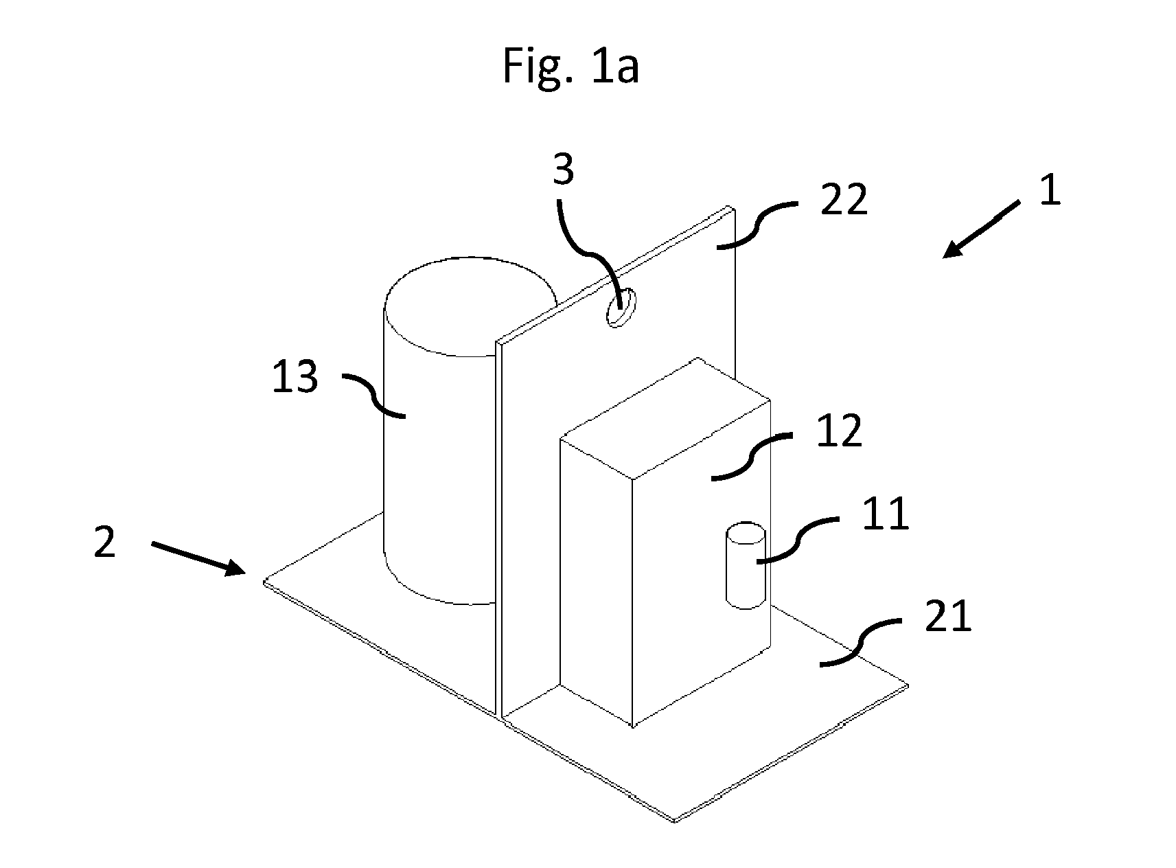
- FIG. 1 schematically shows a perspective view of a base unit 1 for placement in a heat pump unit 10.
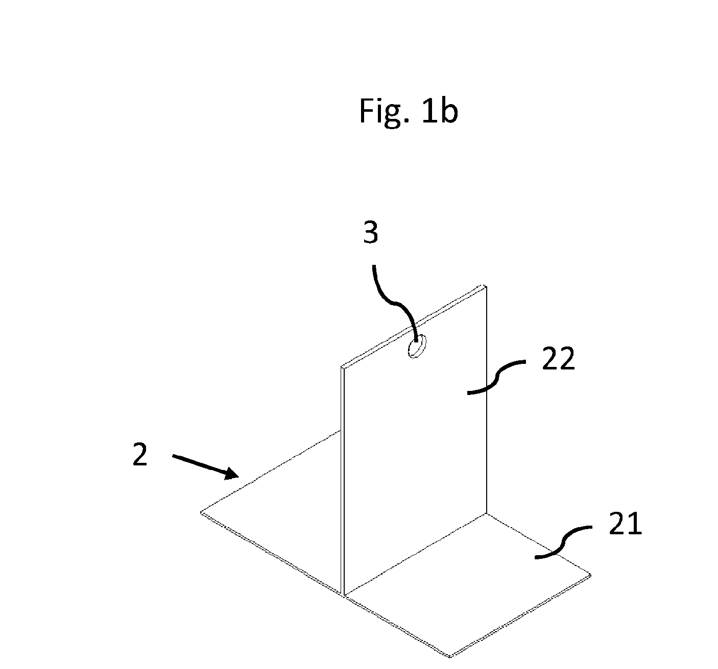
- the base unit 1 comprises a frame 2 which is shown in Fig. 1b .
- the base unit as shown in Fig. 1a comprises a plurality of heat pump components 11, 12, 13, which are depicted schematically.
- the heat pump components are attached to the frame 2.
- the heat pump components are configured to carry a refrigerant and are an expansion valve 11, a first heat exchanger 12 and a compressor 13.
- the heat pump components can also be hydraulic components.
- the first heat exchanger 12 may be a heat exchanger configured to transfer heat from a refrigerant to a destination medium such as water.
- a heat pump unit used for heating purposes this may be a condenser.
- a heat pump unit used for cooling purposes this may be an evaporator.
- a further heat pump component may be a second heat exchanger, which is configured to exchange heat between a source medium (e.g. air) and the refrigerant.
- this second heat exchanger is not comprised by the base unit 1.
- a heat pump unit used for heating purposes this may be an evaporator.
- a heat pump unit used for cooling purposes this may be a condenser.
- the heat pump components configured to carry a refrigerant may be interconnected by piping 15 to form a heating cycle.
- the piping 15 is schematically depicted in Fig. 1c , showing a side view of the base unit 1 of Fig. 1a .
- the frame 2 as can best be seen in Fig. 1b , comprises a bottom plate 21 and a lifting plate 22 attached to the bottom plate 21.
- the lifting plate comprises the lifting point.
- the lifting plate 22 is positioned vertically, the bottom plate 21 is positioned horizontally.
- the lifting plate 22 divides the bottom plate 21 in two parts. This allows to position heat pump components on opposite sides of the lifting plate 22, providing a balanced base unit 1.
- the compressor 22 is positioned on one side of the lifting plate 22, the first heat exchanger 12 is positioned on the opposite side of the lifting plate 22.
- the frame 2 comprises a lifting point 3.
- the lifting point is provided as a hole in the frame 2.
- Fig.'s 1a-c show an embodiment with a single lifting point 3, which is positioned above the centre of gravity of the base unit 1 to allow balanced lifting.
- Fig. 2a-c show an alternative embodiment, having two or more lifting points 3, in this case four lifting points 3.
- the embodiment shown in these figures comprise a frame 2 (best shown in Fig. 2b ), having a horizontal rectangular bottom plate 21 and two upward lifting plates 22 connected along opposing edge of the bottom plate to create a U-shape.
- Each lifting plate 22 comprises two lifting points 3.
- the four lifting points 3 are located in a predetermined range around the centre of gravity of the base unit 1. When lifting the base unit 1, all four lifting points 3 can be used at the same time, thereby creating a balanced lift.
- Fig. 3a shows a more detailed view of a base unit 1 and a heat pump unit 10.
- the heat pump unit 10 comprises a housing formed by a heat pump unit base plate 16 and a plurality of panels, connected to the heat pump unit base plate directly or indirectly.
- the housing may comprise a number of side panels directly connected to the heat pump unit base plate 16 with a top panel to close the housing.
- part of the side panels are removed to make the internals of the heat pump unit 10 visible.
- On the right-hand side there is provided a base unit 1 comprising a frame 2 and an expansion valve 11 that is shown in fig. 3b , a first heat exchanger 12 and a compressor 13.
- the base unit 1 further comprises piping 15.
- the base unit 1 further comprises heat pump components not being configured for carrying a refrigerant, such as a pump 23, a filter 26, a probe (not visible), an air vent 24, a flow meter 25, a sensor and hydraulic connections 17.
- the base unit 1 is positioned on the heat pump unit base plate 16.
- the heat pump unit 10 further comprises a second heat exchanger (not visible).
- Fig. 3b schematically shows the base unit 1 of Fig. 3a in isolation wherein some heat pump components are arranged on the base unit 1
- the base unit 1 is positioned in the heat pump unit 10 such that it can be removed or positioned by lifting the base unit 1 by means of the lifting point(s) 3. if the top panel and/or a side panel is removed.
- a heat pump unit 10 This allows to assemble a heat pump unit 10 by providing a base plate 16 of a heat pump unit 10 and providing a base unit 1 as described above.
- the base unit 1 can be connected to a lifting device, like a crane, by means of the one or more lifting points.
- the connection can be made with a hook or carabiner or any other suitable means.
- the lifting device can lift the base unit 1, position it above the base plate 16 and lowering the base unit to the intended position on the base plate 16, where it can be secured.
- assembling the heat pump unit 10 may comprise further steps, like placing further components, making connections etc.
- the top panel and/or the side panel can be removed and the base unit 1 can be removed from the heat pump unit 10 by lifting the base unit by means of the one or more lifting points.
Landscapes
- Engineering & Computer Science (AREA)
- Chemical & Material Sciences (AREA)
- Combustion & Propulsion (AREA)
- Mechanical Engineering (AREA)
- General Engineering & Computer Science (AREA)
- Other Air-Conditioning Systems (AREA)
Abstract
The invention relates to a base unit (1) for placement in a heat pump unit (10). The base unit (1) comprises a frame (2) and a plurality of heat pump components (11, 12, 13). The heat pump components (11, 12, 13) are attached to the frame (2), wherein the base unit (1) comprises at least one lifting point (3).
Description
- The invention relates to a base unit for placement in a heat pump unit. The invention further relates to a heat pump unit comprising such a base unit and a method of assembling, disassembling or maintaining such a heat pump unit.
- Heat pump units are widely used for heating and cooling purposes.
- The heat pump market is evolving and new industrial integration methods are being implemented to facilitate mass production. In addition, environmental standards limit the use of old refrigerants and must be replaced by new fluids that are less polluting for the environment. These fluids are generally natural fluids that are explosive or flammable. The use of these hazardous fluids, the emphasis on product reusability and the increasing number of units are leading to new ways of assembly and maintenance.
- Heat pump units comprise a variety of components. For instance, air-source heat pump units have at least one refrigeration circuit comprising a compressor, a water/refrigerant heat exchanger, an expansion valve and an air/refrigerant heat exchanger.
- Heat pump units comprise a housing, formed by a base plate and a plurality of panels (side panels, top panel) creating an inner space in which several heat pump components are placed.
- Upon manufacturing, components are usually directly assembled to the base plate of the heat pump before any panels are present. The base plate is usually flat.
- The heat pump components are gradually positioned and connected. Some heat pump components are directly fixed to the based plate using screws, rivets, brazing, ties etc. Other heat pump components may be fixed to the base plate indirectly, i.e. via one or more other heat pump components. One example is the compressor, which may be fixed to an intermediate and independent plate resting on anti-vibration pads. The anti-vibration pads are connected to the base plate. This solution allows the compressor and the vibrations generated during its operation to be decoupled from the rest of the heat pump unit in a more efficient manner.
- Next, additional heat pump components, like structure, air ducting, casing, electrical connections etc. are then assembled around and on top of this assembly of a base plate with heat pump components connected to the base plate.
- When all heat pump components to be positioned in the inner space of the housing are present, the side and top panels are provided and attached to finish the heat pump unit.
- This assembly process is interesting as it limits the number of assembly parts to a minimum, as all parts are mounted directly on the product without any additional parts added for manufacturing purposes only. However, this manner of assembling a heat pump unit has several drawbacks.
- While it is a relatively easy way to manufacture the heat pump unit, it is not necessarily helpful for the ergonomics of staff.
- Ergonomics for the assembled heat pump unit and maintenance thereof is difficult from an ergonomic point of view as the various tasks to be performed are carried out directly on the level of the base plate.
- Access to some heat pump components once the product is installed may be difficult or impossible, making maintenance more difficult. Indeed, some components may cover or block access or view of other heat pump components. This makes maintenance of the heat pump unit time consuming, as it requires removing one or more side panels to get access to some heat pump components.
- Some manufacturing steps take quite some time, and all work has to be done starting from the base plate.
- Furthermore, the manufacturing and assembly process imposes constraints on the production line, in particular through the integration of long and non-dissociable tasks such as the brazing of the heat pump components. These constraints can lead to a bottleneck in the production line and therefore lead to additional assembly time and production cost.
- The object of the invention is to provide an improved manner of assembling and maintaining a heat pump unit.
- The object is solved by providing a base unit for placement in a heat pump unit, wherein the base unit comprises a frame and a plurality of heat pump components, the heat pump components being attached to the frame wherein the base unit comprises at least one lifting point.
- The heat pump components may be directly attached to the frame or may be attached to another component which is directly or indirectly attached to the frame, such that they can be lifted together with the frame.
- The lifting point is advantageously provided on the frame. The lifting point may also be provided on one or more of the heat pump components attached to the frame.
- By providing a separate base unit which can be inserted into a (nearly) finished heat pump unit, assembly is made easier. This allows for modularity, where the base unit can be assembled on a different assembly line. The base unit can be taken out as a whole for maintenance without the need to remove or open all panels and without removing other parts (like the fan or second heat exchanger).
- Assembly and maintenance are improved by providing a base unit with attached heat pump components. This allows insertion and removal of the base unit as a functional block in and out of the heat pump unit. The base unit can be inserted into a (nearly) finished heat pump housing or casing. This allows certain modularity, as one can have most heat pump components on the base unit, where that base unit may be assembled on a different production line. The base unit can be taken out as a whole for maintenance without having to open all panels or removing, for instance, the fan. By having a lifting point at the base unit placing and replacing the base unit as a whole is facilitated.
- The provided solution offers more options for assembly by allowing tasks to be carried out outside the heat pump unit by disassembling and removing the base unit. This allows better access to all components and greatly improved ergonomics. The fact of having a better access also makes it possible to improve the soldering and to avoid leaks associated with a bad soldering (bad access, bad visibility etc...).
- The base unit also makes it possible to dissociate the production of the base unit from the production of the rest of the heat pump unit, such as the structure and the housing on a production line. This offers greater production flexibility and thus the ability to produce a wider range of products that are more accurately adapted to consumer needs (delayed customization).
- This solution improves the ergonomics of the users (fitters, repairers, recyclers) and their safety by allowing the base unit to be carried by a lifting device. Indeed, this type of base unit generally weighs at least 15 kg.
- In the event of an unidentified failure of the heat pump unit, this design also allows for easy replacement of the entire base unit. Replacing the base unit allows for easy transport and ensures that the base unit meets industry requirements. The failed base unit can also be easily shipped back to the manufacturer for analysis of the cause of the failure and reconditioning of the base unit.
- The provision of the base unit also reduces the risk of bad assembly that happens when an installer changes a heat pump unit component directly in the heat pump unit. The bad assembly can result from bad access and/or visibility and/or not have an ergonomic position when doing maintenance in the heat pump unit.
- In an embodiment in which flammable refrigeration is used, it is also safer to change the whole assembly of heat pump unit component instead of a single element. This reduces the risk of leakage of flammable refrigerant in the environment.
- According to an embodiment the frame is made of metal and/or plastic. The frame is preferably made of sheet metal, in particular folded sheet metal.
- According to an embodiment the frame comprises a bottom plate. One or more of the heat pump components may be positioned on the bottom plate The bottom plate can carry several heat pump components. The bottom plate can be easily placed and fixed inside a heat pump unit, i.e. in the housing of a heat pump unit. The bottom plate can have a shape and the heat pump unit can have a corresponding countershape for facilitating fixing the components to each other.
- According to an embodiment the frame comprises one or more lifting plates attached to the bottom plate, each lifting plate comprising one or more lifting points.
- Lifting plate may perpendicularly connected on the bottom plate, or with a small angle deviating from perpendicular (± 5°). By providing lifting plates which are projecting upwardly from the bottom plate, the lifting points can be provided in an accessible manner and above the centre of gravity of the base unit, in particular the centre of gravity of the frame and the heat pump components arranged on the frame, respectively. Such positioning of the lifting points provides stability when lifted and prevents the whole assembly from tipping over. "Above" refers to gravity direction.
- According to an embodiment at least one heat pump unit component is attached to the bottom plate and at least one other heat pump unit component is attached to the lifting plate.
- Whether the heat pump unit component is attached to the bottom plate or to the lifting plate can depend on one more factors, like reliability, feasability or compacity. For example, a compressor can be fixed on the horizontal bottom plate because it is the only fixing points of the compressor and it needs to stay vertical when running. On the other hand, a plate heat exchanger, a bottle, a pipe, a pump etc. can be installed vertically and does not need to rest on the bottom so it is more compact to install it on a vertical plane such as the lifting plate.
- Preferably, the compressor is attached to the bottom plate and a, in particular plate, heat exchanger is fixed to the lifting plate. Such an embodiment is advantageous when the heat pump unit is a monobloc heat pump to heat and/or cool water. Likewise to other embodiments discussed before and after, the lifting point can be arranged in the lifting plate and/or in the heat pump component unit attached to the frame of the base unit.
- According to an embodiment the frame comprises a lifting plate which is attached to a section of the bottom plate. The location of the section of the bottom plate depends on the positon of the center of gravity of the base unit. The lifting plate can be arranged such that the centre of gravity is arranged within the lifting plate or is arranged within a predetermined range adjacent to the lifting plate. In particular, the centre of gravity can be arranged adjacent to the lifting portion in a direction perpendicular to a lifting plate and/or gravity direction. This in combination to the fact that the lifting point is arranged above the centre of gravity, in particular withing a predetermined range above the centre of gravity, of the base unit facilitates a balanced lift when the base unit is lifted by means of the lifting point provided in the lifting plate.
- The bottom plate may be a rectangular plate having a width and a length. The lifting plate may have at least one outer edge having a length substantially equal to the width of the bottom plate, which outer edge is attached to the bottom plate parallel to the width.
- According to an embodiment a first heat pump component is positioned on a first side of the base unit and a second heat pump component is positioned on a second side of the base unit, the second side being separated by the lifting late from the first side and being opposite of the first side. The two sides are arranged opposite to each other referring to the lifting plate. The first heat pump component can be a compressor and the at least one second heat pump component can be a heat exchanger or a refrigerant pipe or a liquid receiver or a hydraulic pipe or a pump. As discussed above for the case that the second heat pump component is a, in particular plate, heat exchanger a monobloc heat pump unit can be provided.
- According to an embodiment the frame comprises two lifting plates the frame being U-shaped, the bottom plate forming the base of the U-shape and the two lifting plates forming the legs of the U-shape.
- The bottom plate may be rectangular or square shaped, with a first lifting plate being attached along a first edge of the bottom plate and a second lifting plate being attached along a second edge of the bottom plate, the first and second edge of the bottom plate being opposite each other.
- By providing lifting plates on opposite sides of the bottom plate, a balanced lift is ensured. As each lifting plate has one or more lifting points, the base unit can be lifted in a stable and balanced manner.
- According to an embodiment, for example in a monobloc heat pump, the heat pump components are configured to carry a refrigerant, the heat pump components being selected from at least one of an expansion valve, a, in particular plate, heat exchanger, a liquid receiver and a compressor. A liquid receiver is a component by means of which a refrigerant is stored, wherein the stored refrigerant is the refrigerant that is not necessary in a heating operation mode of the heat pump unit or in the cooling operation mode of the heat pump.
- The heat exchanger may be a first heat exchanger, being a destination medium/refrigerant heat exchanger. The destination medium is the medium to be heated or cooled by the heat pump unit. The destination medium may be water. The refrigerant may be propane (R290), R32, R1234yf, R1234ze, R744 (CO2), R452B or R410.....
- Optionally, the heat pump components configured to carry a refrigerant attached to the frame may comprise a second heat exchanger, being a source medium/refrigerant heat exchanger. The source medium is the medium from which heat or cold is used by the heat pump unit to heat or cool the destination medium. The source medium may be air or water. The destination medium can be water or brine and/or can circulate in a closed loop.
- Furthermore, the heat pump components configured to carry a refrigerant attached to the frame may comprise refrigerant piping connecting the expansion valve, compressor and at least one heat exchanger to form (part of) a refrigeration circuit.
- According to an embodiment the base unit comprises further heat pump components being selected at least one from a pump, a filter, a probe, a cylinder, a sensor, a hydraulic connection, an air vent and a flow meter. The hydraulic connection can be a hydraulic pipe.
- According to an embodiment the lifting points are provided by holes, configured to receive a hook, a pin or a carabiner.
- According to an embodiment the base unit comprises a single lifting point located in a predetermined range around the center of gravity, in particular above the center of gravity, of the base unit, or two or more lifting points each of which located in a predetermined range around the center of gravity, in particular above the center of gravity, of the base unit.
- In the embodiment comprising two or more lifting points, each of the lifting points does not need to be located at the centre of gravity in a horizontal direction. Only the barycentre of these lifting holes need to be positioned above the center of gravity. In a vertical direction the lifting points have to be higher than the center of gravity of the assembly.
- According to an aspect there is provided a heat pump unit comprising a housing, the housing comprising a heat pump unit base plate and a plurality of panels connected to the heat pump unit base plate, the heat pump unit further comprising a base unit according to any one of the preceding claims, wherein the base unit is positioned on the base plate. The base unit can be directly or indirectly positioned on the base plate.
- The base unit may be positioned directly on the base plate or indirectly, as interface parts such as anti-vibration pads may be provided in between the base unit and the base plate. The interface parts can for example be a foam based material, in particular a foamed plastic that is positioned between the base plate and the base unit. The base plat can rest on an interface part in foam based material and/or on an anti-vibration pad in elastomer plastic. The housing may be formed by a plurality of panels, which may comprise a plurality of side panels and a top panel.
- According to an aspect there is provided a method of assembling a heat pump unit, the method comprising
- a) providing a base plate of a heat pump unit,
- b) providing a base unit as described,
- c) connecting a lifting device to the one or more lifting points,
- d) positioning the base unit on the base plate by lifting and lowering the base unit with the lifting device.
- Action a) may comprise providing a housing, comprising a heat pump unit base plate and a plurality of side panels connected to the heat pump unit base plate. The lifting device may be a small crane or the like. The lifting device may comprise a hook, a pin or a carabiner which can be attached to the lifting point. Action d) may comprise lifting the base unit to a position above the base plate and lowering the base unit to the base plate. Additionally the base unit can be secured in the heat pump. This is needed to ensure that the base unit stays in position compared to the base plate. The base unit can be screwed, clipsed or assembled with any fixing solution to the base plate.
- The method may further comprise additional steps, like step e) connecting the heat pump components configured to carry a refrigerant to other heat pump components configured to carry a refrigerant which are not part of the base unit, such as for instance the fan/second heat exchanger. Additionally, the base unit, in particular their components, can be connected to other components of the heat pump unit, like the refrigerant or hydraulic pipes, sensor, power supplies, etc.. The method may further comprise step f) closing the heat pump unit by providing one or more side panels and/or a top panel.
- According to a further aspect there is provided a method of disassembling or maintaining a heat pump unit as described, wherein the method comprises
- a') removing a panel, in particular a top panel and/or a side panel, of the heat pump unit,
- b') connecting a lifting device to the one or more lifting points,
- c') lifting the base unit as described out of the housing with the lifting device.
- The base unit has to be disconnected from the base plate of the heat pump unit. Additionally, the components of the base unit have to be disconnected from other components of the heat pump. This can be done before step b' or before step c'.
- The method may further comprise performing maintenance, positioning the same or a different base unit on the base plate with the lifting device, disconnecting the lifting device and repositioning the top panel of the heat pump unit.
- In the figures, the subject-matter of the invention is schematically shown, wherein identical or similarly acting elements are usually provided with the same reference signs.
- Figures 1a-c
- schematically show a base unit and a frame according to an embodiment,
- Figures 2a-c
- schematically show a base unit and a frame according to an alternative embodiment,
- Figure 3a
- schematically shows a perspective view of a heat pump unit comprising a base unit according to an embodiment, and
- Figures 3b
- schematically shows a perspective view of a base unit according to an embodiment.
-
Figure 1 schematically shows a perspective view of abase unit 1 for placement in aheat pump unit 10. Thebase unit 1 comprises aframe 2 which is shown inFig. 1b . The base unit as shown inFig. 1a comprises a plurality ofheat pump components frame 2. The heat pump components are configured to carry a refrigerant and are anexpansion valve 11, afirst heat exchanger 12 and acompressor 13. The heat pump components can also be hydraulic components. Thefirst heat exchanger 12 may be a heat exchanger configured to transfer heat from a refrigerant to a destination medium such as water. For a heat pump unit used for heating purposes this may be a condenser. For a heat pump unit used for cooling purposes this may be an evaporator. - A further heat pump component may be a second heat exchanger, which is configured to exchange heat between a source medium (e.g. air) and the refrigerant. In the embodiments depicted in the figures, this second heat exchanger is not comprised by the
base unit 1. For a heat pump unit used for heating purposes this may be an evaporator. For a heat pump unit used for cooling purposes this may be a condenser. - The heat pump components configured to carry a refrigerant may be interconnected by piping 15 to form a heating cycle. The piping 15 is schematically depicted in
Fig. 1c , showing a side view of thebase unit 1 ofFig. 1a . - The
frame 2, as can best be seen inFig. 1b , comprises abottom plate 21 and a liftingplate 22 attached to thebottom plate 21. The lifting plate comprises the lifting point. The liftingplate 22 is positioned vertically, thebottom plate 21 is positioned horizontally. - As shown in
Fig. 1a , the liftingplate 22 divides thebottom plate 21 in two parts. This allows to position heat pump components on opposite sides of the liftingplate 22, providing abalanced base unit 1. In the embodiment shown inFig. 1a , thecompressor 22 is positioned on one side of the liftingplate 22, thefirst heat exchanger 12 is positioned on the opposite side of the liftingplate 22. - The
frame 2 comprises alifting point 3. The lifting point is provided as a hole in theframe 2. - Fig.'s 1a-c show an embodiment with a
single lifting point 3, which is positioned above the centre of gravity of thebase unit 1 to allow balanced lifting. -
Fig. 2a-c show an alternative embodiment, having two ormore lifting points 3, in this case four lifting points 3. The embodiment shown in these figures comprise a frame 2 (best shown inFig. 2b ), having a horizontalrectangular bottom plate 21 and twoupward lifting plates 22 connected along opposing edge of the bottom plate to create a U-shape. Each liftingplate 22 comprises two lifting points 3. The fourlifting points 3 are located in a predetermined range around the centre of gravity of thebase unit 1. When lifting thebase unit 1, all fourlifting points 3 can be used at the same time, thereby creating a balanced lift. -
Fig. 3a shows a more detailed view of abase unit 1 and aheat pump unit 10. Theheat pump unit 10 comprises a housing formed by a heat pumpunit base plate 16 and a plurality of panels, connected to the heat pump unit base plate directly or indirectly. The housing may comprise a number of side panels directly connected to the heat pumpunit base plate 16 with a top panel to close the housing. InFig. 3a part of the side panels are removed to make the internals of theheat pump unit 10 visible. On the right-hand side there is provided abase unit 1 comprising aframe 2 and anexpansion valve 11 that is shown infig. 3b , afirst heat exchanger 12 and acompressor 13. Thebase unit 1 further comprises piping 15. Thebase unit 1 further comprises heat pump components not being configured for carrying a refrigerant, such as apump 23, afilter 26, a probe (not visible), anair vent 24, aflow meter 25, a sensor andhydraulic connections 17. Thebase unit 1 is positioned on the heat pumpunit base plate 16. Theheat pump unit 10 further comprises a second heat exchanger (not visible). -
Fig. 3b schematically shows thebase unit 1 ofFig. 3a in isolation wherein some heat pump components are arranged on thebase unit 1 - As can be seen in
Fig. 3a thebase unit 1 is positioned in theheat pump unit 10 such that it can be removed or positioned by lifting thebase unit 1 by means of the lifting point(s) 3. if the top panel and/or a side panel is removed. - This allows to assemble a
heat pump unit 10 by providing abase plate 16 of aheat pump unit 10 and providing abase unit 1 as described above. Thebase unit 1 can be connected to a lifting device, like a crane, by means of the one or more lifting points. The connection can be made with a hook or carabiner or any other suitable means. The lifting device can lift thebase unit 1, position it above thebase plate 16 and lowering the base unit to the intended position on thebase plate 16, where it can be secured. It will be understood that assembling theheat pump unit 10 may comprise further steps, like placing further components, making connections etc. - When the
heat pump unit 10 needs to be maintained or disassemble, the top panel and/or the side panel can be removed and thebase unit 1 can be removed from theheat pump unit 10 by lifting the base unit by means of the one or more lifting points. -
- 1.
- Base unit
- 2.
- Frame
- 3.
- Lifting point
- 10.
- Heat pump unit
- 11.
- Expansion valve
- 12.
- First heat exchanger
- 13.
- Compressor
- 15.
- Piping
- 16.
- Heat pump unit base plate
- 17.
- Hydraulic connections
- 21.
- Bottom plate
- 22.
- Lifting plate
- 23.
- Pump
- 24.
- Air vent
- 25.
- Flowmeter
- 26.
- Filter
Claims (15)
- Base unit (1) for placement in a heat pump unit (10), wherein the base unit (1) comprises a frame (2) and a plurality of heat pump components (11, 12, 13), the heat pump components (11, 12, 13) being attached to the frame (2), wherein the base unit (1) comprises at least one lifting point (3).
- Base unit (1) according to claim 1, wherein the frame (2) is made of metal and/or plastic.
- Base unit (1) according to any one of the preceding claims, wherein the frame (2) comprises a bottom plate (21).
- Base unit (1) according to claim 3, wherein the frame (2) comprises one or more lifting plates (22) attached to the bottom plate (21), each lifting plate (22) comprising one or more lifting points (3).
- Base unit (1) according to claim 4, wherein at least one heat pump unit component is attached to the bottom plate (21) and at least one other heat pump unit component is attached to the lifting plate (22).
- Base unit (1) according to claim 4 or 5, wherein the frame (2) comprises a lifting plate (22) which is attached to a section of the bottom plate (21), wherein the location of the section of the bottom plate depends on the position of the center of gravity of the base unit (1).
- Base unit (1) according to at least one of the claims 4 to 6, wherein a first heat pump component is positioned on a first side of the base unit (1) and a second heat pump component is positioned on a second side of the base unit (1), the second side being separated by the lifting plate (22) from the first side and being opposite of the first side, the first heat pump component being a compressor (13) and the at least one second heat pump component being a heat exchanger (12), preferably a plate heat exchanger, or a refrigerant pipe or a liquid receiver or a hydraulic pipe or a pump.
- Base unit (1) according to claim 4, wherein the frame (2) comprises two lifting plates (22), the frame (2) being U-shaped, the bottom plate (21) forming the base of the U-shape and the two lifting plates (22) forming the legs of the U-shape.
- Base unit (1) according to any one of the preceding claims, wherein the heat pump components are configured to carry a refrigerant, the heat pump components being selected from at least one of an expansion valve (11), a heat exchanger (12), a liquid receiver and a compressor (13).
- Base unit (1) according to any one of the preceding claims, wherein the base unit (1) comprises further heat pump components being selected from at least one of a pump, a filter, a probe, a cylinder, a sensor, a hydraulic connection (17), an air vent and a flow meter.
- Base unit (1) according to any one of the preceding claims, wherein the lifting points (3) are provided by holes, configured to receive a hook, a pin or a carabiner.
- Base unit (1) according to any one of the preceding claims, comprising- a single lifting point (3) located in a predetermined range around the center of gravity, in particular above the center of gravity, of the base unit (1), or- two or more lifting points (3) each of which located in a predetermined range around the center of gravity, in particular above the center of gravity, of the base unit (1).
- Heat pump unit (10) comprising a housing, the housing comprising a heat pump unit base plate (16) and a plurality of panels connected to the heat pump unit base plate (16), the heat pump unit (1) further comprising a base unit (1) according to any one of the preceding claims, wherein the base unit (1) is positioned on the heat pump unit base plate (16).
- Method of assembling a heat pump unit (10), the method comprisinga) providing a base plate (16) of a heat pump unit (10),b) providing a base unit (1) according to any one of the claims 1 - 12,c) connecting a lifting device to the one or more lifting points (3) from the base unit (1),d) positioning the base unit (1) on the base plate (16) by lifting and lowering the base unit (1) with the lifting device.
- Method of disassembling or maintaining a heat pump unit (10) according to claim 13, wherein the method comprisesa') removing a panel of the heat pump unit (10),b') connecting a lifting device to the one or more lifting points (3) from the base unit (1),c') lifting the base unit (1) according to any one of the claims 1-12 out of the housing with the lifting device.
Priority Applications (3)
| Application Number | Priority Date | Filing Date | Title |
|---|---|---|---|
| EP23171786.9A EP4459196A1 (en) | 2023-05-05 | 2023-05-05 | Base unit for a heat pump |
| PCT/EP2024/062129 WO2024231228A1 (en) | 2023-05-05 | 2024-05-02 | Base unit for a heat pump |
| EP24723838.9A EP4705690A1 (en) | 2023-05-05 | 2024-05-02 | Base unit for a heat pump |
Applications Claiming Priority (1)
| Application Number | Priority Date | Filing Date | Title |
|---|---|---|---|
| EP23171786.9A EP4459196A1 (en) | 2023-05-05 | 2023-05-05 | Base unit for a heat pump |
Publications (1)
| Publication Number | Publication Date |
|---|---|
| EP4459196A1 true EP4459196A1 (en) | 2024-11-06 |
Family
ID=86330277
Family Applications (2)
| Application Number | Title | Priority Date | Filing Date |
|---|---|---|---|
| EP23171786.9A Withdrawn EP4459196A1 (en) | 2023-05-05 | 2023-05-05 | Base unit for a heat pump |
| EP24723838.9A Pending EP4705690A1 (en) | 2023-05-05 | 2024-05-02 | Base unit for a heat pump |
Family Applications After (1)
| Application Number | Title | Priority Date | Filing Date |
|---|---|---|---|
| EP24723838.9A Pending EP4705690A1 (en) | 2023-05-05 | 2024-05-02 | Base unit for a heat pump |
Country Status (2)
| Country | Link |
|---|---|
| EP (2) | EP4459196A1 (en) |
| WO (1) | WO2024231228A1 (en) |
Citations (4)
| Publication number | Priority date | Publication date | Assignee | Title |
|---|---|---|---|---|
| US5444990A (en) * | 1994-01-25 | 1995-08-29 | Inter-City Products Corporation | Reversible fan assembly panel for package air conditioners and heat pumps |
| CN209944798U (en) * | 2019-04-15 | 2020-01-14 | 河北程龙暖通设备科技有限公司 | Air source heat pump |
| EP3611440A1 (en) * | 2018-08-14 | 2020-02-19 | Robert Bosch GmbH | Heat pump and blower for a heat pump |
| CN111895648A (en) * | 2020-08-06 | 2020-11-06 | 烽海新能源科技(上海)有限公司 | Energy-saving heat pump device for swimming pool |
Family Cites Families (3)
| Publication number | Priority date | Publication date | Assignee | Title |
|---|---|---|---|---|
| AT502829B1 (en) * | 2006-02-28 | 2007-06-15 | Neura Electronics Tech Anlagen | Heat pump, has plug-in couplings with coupling parts provided for detachably connecting feed- and discharge lines to cooling medium circuit, where coupling parts are self-lockable and are held opposite to each other in coupling bodies |
| CN107076433B (en) * | 2014-12-26 | 2019-08-27 | 三菱电机株式会社 | The outdoor unit |
| DE102017203626A1 (en) * | 2017-03-06 | 2018-09-06 | Glen Dimplex Deutschland Gmbh | Modular heat pump system |
-
2023
- 2023-05-05 EP EP23171786.9A patent/EP4459196A1/en not_active Withdrawn
-
2024
- 2024-05-02 WO PCT/EP2024/062129 patent/WO2024231228A1/en not_active Ceased
- 2024-05-02 EP EP24723838.9A patent/EP4705690A1/en active Pending
Patent Citations (4)
| Publication number | Priority date | Publication date | Assignee | Title |
|---|---|---|---|---|
| US5444990A (en) * | 1994-01-25 | 1995-08-29 | Inter-City Products Corporation | Reversible fan assembly panel for package air conditioners and heat pumps |
| EP3611440A1 (en) * | 2018-08-14 | 2020-02-19 | Robert Bosch GmbH | Heat pump and blower for a heat pump |
| CN209944798U (en) * | 2019-04-15 | 2020-01-14 | 河北程龙暖通设备科技有限公司 | Air source heat pump |
| CN111895648A (en) * | 2020-08-06 | 2020-11-06 | 烽海新能源科技(上海)有限公司 | Energy-saving heat pump device for swimming pool |
Also Published As
| Publication number | Publication date |
|---|---|
| WO2024231228A1 (en) | 2024-11-14 |
| EP4705690A1 (en) | 2026-03-11 |
Similar Documents
| Publication | Publication Date | Title |
|---|---|---|
| EP2792955A1 (en) | Heater and outdoor unit for refrigeration unit provided with heater | |
| CN104520649B (en) | Outdoor unit of refrigeration cycle plant | |
| CN103261819B (en) | Evaporator | |
| WO2006122065A2 (en) | Shipping and installation for heating, ventilation, and air conditioning (hvac) | |
| JPWO2019167168A1 (en) | Air conditioner | |
| CA2455297C (en) | Modular heating or cooling system | |
| US10001304B2 (en) | Heat medium relay unit and air-conditioning apparatus including the heat medium relay unit | |
| US20130219942A1 (en) | Air Conditioner and Heat Pump Condensing Unit Chassis with Enhanced Serviceability Access | |
| EP4679006A1 (en) | Heat source equipment and refrigeration cycle device | |
| JP2022146443A (en) | Outdoor unit of freezer | |
| CN108027153B (en) | Outdoor machine | |
| CN117120787B (en) | Refrigeration equipment | |
| WO2024231228A1 (en) | Base unit for a heat pump | |
| EP3124890B1 (en) | Heat-generating unit | |
| EP3309475B1 (en) | Refrigeration cycle device and refrigeration cycle system | |
| EP4242536A1 (en) | Modular air guiding assembly | |
| JP7286859B1 (en) | refrigeration equipment | |
| JP5627542B2 (en) | Heat medium converter | |
| EP4490444A1 (en) | Modular air guiding assembly | |
| JP2016180544A (en) | Air conditioner | |
| JPWO2019229918A1 (en) | Outdoor unit of air conditioner | |
| JP7515662B1 (en) | Refrigeration equipment | |
| WO2025186908A1 (en) | Outdoor unit and heat pump device | |
| JP2005076923A (en) | Air conditioner outdoor unit | |
| CN208588005U (en) | Outdoor unit of air conditioner |
Legal Events
| Date | Code | Title | Description |
|---|---|---|---|
| PUAI | Public reference made under article 153(3) epc to a published international application that has entered the european phase |
Free format text: ORIGINAL CODE: 0009012 |
|
| STAA | Information on the status of an ep patent application or granted ep patent |
Free format text: STATUS: THE APPLICATION HAS BEEN PUBLISHED |
|
| AK | Designated contracting states |
Kind code of ref document: A1 Designated state(s): AL AT BE BG CH CY CZ DE DK EE ES FI FR GB GR HR HU IE IS IT LI LT LU LV MC ME MK MT NL NO PL PT RO RS SE SI SK SM TR |
|
| STAA | Information on the status of an ep patent application or granted ep patent |
Free format text: STATUS: THE APPLICATION IS DEEMED TO BE WITHDRAWN |
|
| 18D | Application deemed to be withdrawn |
Effective date: 20250507 |