EP4459191A1 - Gas turbine combustor - Google Patents
Gas turbine combustor Download PDFInfo
- Publication number
- EP4459191A1 EP4459191A1 EP22915951.2A EP22915951A EP4459191A1 EP 4459191 A1 EP4459191 A1 EP 4459191A1 EP 22915951 A EP22915951 A EP 22915951A EP 4459191 A1 EP4459191 A1 EP 4459191A1
- Authority
- EP
- European Patent Office
- Prior art keywords
- head
- air
- fixture
- wall
- liner
- Prior art date
- Legal status (The legal status is an assumption and is not a legal conclusion. Google has not performed a legal analysis and makes no representation as to the accuracy of the status listed.)
- Pending
Links
Images


Classifications
-
- F—MECHANICAL ENGINEERING; LIGHTING; HEATING; WEAPONS; BLASTING
- F23—COMBUSTION APPARATUS; COMBUSTION PROCESSES
- F23R—GENERATING COMBUSTION PRODUCTS OF HIGH PRESSURE OR HIGH VELOCITY, e.g. GAS-TURBINE COMBUSTION CHAMBERS
- F23R3/00—Continuous combustion chambers using liquid or gaseous fuel
- F23R3/002—Wall structures
-
- F—MECHANICAL ENGINEERING; LIGHTING; HEATING; WEAPONS; BLASTING
- F23—COMBUSTION APPARATUS; COMBUSTION PROCESSES
- F23R—GENERATING COMBUSTION PRODUCTS OF HIGH PRESSURE OR HIGH VELOCITY, e.g. GAS-TURBINE COMBUSTION CHAMBERS
- F23R3/00—Continuous combustion chambers using liquid or gaseous fuel
- F23R3/005—Combined with pressure or heat exchangers
-
- F—MECHANICAL ENGINEERING; LIGHTING; HEATING; WEAPONS; BLASTING
- F23—COMBUSTION APPARATUS; COMBUSTION PROCESSES
- F23R—GENERATING COMBUSTION PRODUCTS OF HIGH PRESSURE OR HIGH VELOCITY, e.g. GAS-TURBINE COMBUSTION CHAMBERS
- F23R3/00—Continuous combustion chambers using liquid or gaseous fuel
- F23R3/02—Continuous combustion chambers using liquid or gaseous fuel characterised by the air-flow or gas-flow configuration
- F23R3/04—Air inlet arrangements
- F23R3/06—Arrangement of apertures along the flame tube
-
- F—MECHANICAL ENGINEERING; LIGHTING; HEATING; WEAPONS; BLASTING
- F23—COMBUSTION APPARATUS; COMBUSTION PROCESSES
- F23R—GENERATING COMBUSTION PRODUCTS OF HIGH PRESSURE OR HIGH VELOCITY, e.g. GAS-TURBINE COMBUSTION CHAMBERS
- F23R3/00—Continuous combustion chambers using liquid or gaseous fuel
- F23R3/42—Continuous combustion chambers using liquid or gaseous fuel characterised by the arrangement or form of the flame tubes or combustion chambers
- F23R3/60—Support structures; Attaching or mounting means
-
- F—MECHANICAL ENGINEERING; LIGHTING; HEATING; WEAPONS; BLASTING
- F23—COMBUSTION APPARATUS; COMBUSTION PROCESSES
- F23R—GENERATING COMBUSTION PRODUCTS OF HIGH PRESSURE OR HIGH VELOCITY, e.g. GAS-TURBINE COMBUSTION CHAMBERS
- F23R2900/00—Special features of, or arrangements for continuous combustion chambers; Combustion processes therefor
- F23R2900/00017—Assembling combustion chamber liners or subparts
-
- Y—GENERAL TAGGING OF NEW TECHNOLOGICAL DEVELOPMENTS; GENERAL TAGGING OF CROSS-SECTIONAL TECHNOLOGIES SPANNING OVER SEVERAL SECTIONS OF THE IPC; TECHNICAL SUBJECTS COVERED BY FORMER USPC CROSS-REFERENCE ART COLLECTIONS [XRACs] AND DIGESTS
- Y02—TECHNOLOGIES OR APPLICATIONS FOR MITIGATION OR ADAPTATION AGAINST CLIMATE CHANGE
- Y02T—CLIMATE CHANGE MITIGATION TECHNOLOGIES RELATED TO TRANSPORTATION
- Y02T50/00—Aeronautics or air transport
- Y02T50/60—Efficient propulsion technologies, e.g. for aircraft
Definitions
- the present disclosure relates to a combustor of a gas turbine.
- a combustion temperature in a gas turbine is increasing.
- a combustor in which a liner is attached inside an outer wall (shell) surrounding a combustion chamber is being devised.
- a fixture that attaches the liner is a fixture which includes: a head supporting the liner; and a cooling air passage located inside the head (see PTL 1).
- the fixture including the cooling air passage has been proposed as the fixture that attaches the liner.
- the entire fixture is not uniformly heated, and especially the head which is exposed to the combustion chamber tends to increase in temperature.
- An object of the present disclosure is to provide a combustor of a gas turbine which suppresses a temperature increase of especially a head of a fixture that attaches a liner to an outer wall.
- a combustor of a gas turbine includes: an outer wall surrounding a combustion chamber; a liner located inside the outer wall and facing the combustion chamber; and a fixture that attaches the liner to the outer wall in a state where there is a gap between the outer wall and the liner.
- the fixture includes: a shaft portion penetrating the outer wall; a head supporting the liner; and a head groove that is located on an outer peripheral surface of the head and includes a first end portion connected to the gap and a second end portion connected to the combustion chamber.
- the above configuration can provide a combustor of a gas turbine which suppresses a temperature increase of especially a head of a fixture that attaches a liner to an outer wall.
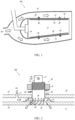
- FIG. 1 is a sectional view of the combustor 100 at a certain circumferential position.
- a central axis (not shown) of the combustor 100 is located at a lower side on a paper surface of FIG. 1 .
- a left-right direction on the paper surface of FIG. 1 is an axial direction of the combustor 100.
- An upper-lower direction on the paper surface of FIG. 1 is a radial direction of the combustor 100 (hereinafter simply referred to as the "radial direction").
- the combustor 100 includes an outer wall 10, a liner 20, and fixtures 30.
- these components will be described in order.
- the outer wall 10 is a member surrounding a combustion chamber 11.
- the outer wall 10 is made of, for example, metal but may be made of a material other than metal.
- the combustion chamber 11 of the present embodiment is annular.
- a portion of the outer wall 10 which is located outside the combustion chamber 11 in the radial direction is a so-called outer shell 12.
- a portion of the outer wall 10 which is located inside the combustion chamber 11 in the radial direction is a so-called inner shell 13.
- the outer wall 10 is surrounded by an annular housing 14, and the outer wall 10 and the combustion chamber 11 are located in an internal space 15 of the housing 14.
- a fuel injector 16 is located in the combustion chamber 11. Fuel is injected from the fuel injector 16 to the combustion chamber 11. Air is supplied to the internal space 15 of the housing 14, and part of the supplied air is supplied to the fuel injector 16. Moreover, as shown by white arrows in FIG. 1 , part of the rest of the air supplied to the internal space 15 flows through a space between the outer wall 10 and the housing 14.
- the liner 20 is a member which is located inside the outer wall 10 and faces the combustion chamber 11.
- the liner 20 of the present embodiment is attached to the outer wall 10.
- the liner 20 of the present embodiment has a plate shape, but the shape of the liner 20 is not limited to this.
- a material of the liner 20 is not limited, either. Examples of the material of the liner 20 include a ceramic material and a metal material.
- the material of the liner 20 is a ceramic matrix composite (CMC).
- the liner 20 is attached to the outer wall 10 by using the fixtures 30 described later.
- the liner 20 may be an assembly of panels lined up in the circumferential direction to have a tubular shape.
- the liner 20 may be integrally molded in a tubular shape without being divided into panels lined up in the circumferential direction.
- FIG. 2 is an enlarged view showing the fixture 30 and its vicinity.
- a lower direction on a paper surface of FIG. 2 is a direction toward the combustion chamber 11 (hereinafter referred to as an "inner direction"), and an upper direction on the paper surface of FIG. 2 is a direction away from the combustion chamber 11 (hereinafter referred to as an "outer direction").
- the same is true in FIGS. 3 to 5 described later.
- the positions of the outer wall 10 and the liner 20 can be determined by inserting a spacer 21, a spring, or the like between the outer wall 10 and the liner 20.
- the positions of the outer wall 10 and the liner 20 may be determined by the fixture 30.
- the outer wall 10 includes an outer wall hole 17. As shown by white arrows in FIG. 2 , air flows into the gap between the outer wall 10 and the liner 20 through the outer wall hole 17. Part of the air supplied to the fuel injector 16 may flow into the gap between the outer wall 10 and the liner 20. The air having flowed into the gap cools the liner 20.
- the shape of means (for example, the spacer 21 or the spring) for forming the gap between the outer wall 10 and the liner 20 is not limited, but the gap is formed such that air can flow through the gap.
- the fixture 30 is a member that attaches the liner 20 to the outer wall 10.
- the fixture 30 is made of, for example, metal but may be made of a material other than metal.
- FIG. 3 is a sectional view of the fixture 30. Strictly speaking, FIG. 3 shows not only a section of the fixture 30 but also the vicinity of the fixture 30.
- the fixture 30 includes a shaft portion 31, a head 32, an air passage 33, air inlets 39, shaft grooves 35, and head grooves 36.
- the fixture 30 includes the shaft grooves 35 but does not have to include the shaft grooves 35.
- the shaft portion 31 is a portion that penetrates the outer wall 10.
- the shaft portion 31 includes a columnar outer portion 37 and a columnar inner portion 38.
- the outer portion 37 is located at an outer side portion of the shaft portion 31, and the inner portion 38 is located at an inner side portion of the shaft portion 31.
- the outer portion 37 and the inner portion 38 are columnar.
- a boundary between the outer portion 37 and the inner portion 38 can be set arbitrarily.
- An outer diameter of the inner portion 38 may be larger than an outer diameter of the outer portion 37.
- a fixing member is fastened to a portion of the inner portion 38 which is located outside the outer wall 10. For example, there is an external screw at a portion of the inner portion 38 which is located outside the outer wall 10, and a nut 41 is fastened to this external screw.
- a spring 42, a spacer, or the like may be inserted between the nut 41 and the outer wall 10, or nothing may be inserted between the nut 41 and the outer wall 10.
- the spring 42 of the present embodiment is a coil spring.
- the type of the spring is not limited, and for example, the spring 42 may be a plate spring or the like. The spring 42 applies outward force to the fixture 30 through the nut 41.
- the head 32 is a portion supporting the liner 20.
- the head 32 is located inside the shaft portion 31.
- An outer diameter of a portion of the head 32 of the present embodiment which is located close to the combustion chamber 11 is larger than an outer diameter of a portion of the head 32 which is located close to the shaft portion 31.
- the head 32 has a shape including a truncated cone shape or a truncated pyramid shape.
- the air passage 33 is a passage through which cooling air flows. As shown in FIG. 3 , the air passage 33 is located inside the fixture 30 from the shaft portion 31 to the head 32 and extends along a central axis direction of the fixture 30. Moreover, the air passage 33 is open in the combustion chamber 11. To be specific, the air passage 33 is connected to the combustion chamber 11.
- the air passage 33 of the present embodiment includes a shape corresponding to the shape of the head 32. For example, each of the shape of the head 32 and the shape of a portion of the air passage 33 which corresponds to the head 32 has a shape including a truncated cone shape or a truncated pyramid shape.
- the thickness (volume) of the head 32 can be reduced, and therefore, heat is hardly accumulated in the head 32. Moreover, a contact area of the portion of the air passage 33 which corresponds to the head 32 with the cooling air can be increased, and therefore, the temperature of the head 32 hardly increases.
- an angle ⁇ of an outer peripheral surface 49 of the head 32 of the air passage 33 with respect to a central axis 101 of the fixture 30 may be 30° or more and 45° or less.
- the angle ⁇ of the outer peripheral surface 49 of the head 32 with respect to the central axis 101 of the fixture 30 is set to 30° or more, the head 32 can surely support the liner 20.
- the angle ⁇ of the outer peripheral surface 49 of the head 32 with respect to the central axis 101 of the fixture 30 is set to 45° or less, the area of an end surface 43 (surface opposed to the combustion chamber 11) of the head 32 decreases, and therefore, the temperature increase of the head 32 can be suppressed.
- An angle of an inner peripheral surface 40 of the head 32 with respect to the central axis 101 of the fixture 30 may be the same as or different from the angle ⁇ of the outer peripheral surface 49 of the head 32 with respect to the central axis 101 of the fixture 30.
- each of the inner peripheral surface 40 and end surface 43 (surface opposed to the combustion chamber 11) of the head 32 may include a thermal barrier coating (TBC) layer on its surface.
- TBC thermal barrier coating
- the TBC layer may be a layer including: a top coating, such as a ceramic coating, for the purpose of a thermal shield effect; and a bond coating, such as an aluminum diffusion coating, for the purpose of oxidation resistance. Since each of the inner peripheral surface 40 and end surface 43 of the head 32 includes the TBC layer on its surface, heat hardly transfers from the combustion chamber 11 to the inner peripheral surface 40 and end surface 43 of the head 32, and therefore, the temperature increase of the head 32 can be suppressed.
- the air inlets 39 are air intake ports through which air is taken in the air passage 33. Then, the air inlets 39 can serve as a swirl generator 34 that makes the air flowing through the air passage 33 swirl.
- the air inlets 39 are located on a side surface of the outer portion 37 of the shaft portion 31. The number of air inlets 39 and the positions of the air inlets 39 are not limited.
- the air inlet 39 is a portion through which air is taken in the air passage 33 from an outside of the fixture 30. In the present embodiment, the taken air serves as cooling air that cools the fixture 30.
- the air taken in through the air inlet 39 flows along a wall surface defining the air passage 33 while swirling in the air passage 33.
- the air inlet 39 extends in a direction perpendicular to the central axis direction of the fixture 30 (i.e., in a direction parallel to the outer wall 10).
- the air inlet 39 may be inclined with respect to the central axis direction of the fixture 30 such that the air easily flows toward the combustion chamber 11.
- the wall surface defining the air passage 33 may include a groove having a spiral shape, and this groove may serve as the swirl generator 34.
- the shaft grooves 35 are grooves located on an outer peripheral surface 48 of the shaft portion 31.
- the fixture 30 includes the shaft grooves 35 but does not have to include the shaft grooves 35.
- the shaft grooves 35 of the present embodiment are located on the outer peripheral surface 48 of the shaft portion 31 at regular intervals in the circumferential direction, and the shaft grooves 35 extend linearly in the central axis direction of the shaft portion 31.
- the shaft groove 35 does not have to extend linearly, and for example, may extend in a spiral shape.
- the number of shaft grooves 35 is not limited.
- An inner end portion (first end portion) of the shaft groove 35 is connected to the head groove 36 described later.
- an outer end portion (second end portion) of the shaft groove 35 may be located between the outer wall 10 and the liner 20 or may be located outside the outer wall 10.
- the shaft groove 35 can be made short, and the fixture 30 can be easily machined.
- the contact area of the fixture 30 with the cooling air is made large. Therefore, the fixture 30 can be effectively cooled.
- the head grooves 36 are grooves located on the outer peripheral surface 49 of the head 32.
- the head grooves 36 of the present embodiment are located on the outer peripheral surface 49 of the head 32 so as to correspond to the shaft grooves 35.
- an outer end portion (first end portion) of the head groove 36 is connected to the gap between the outer wall 10 and the liner 20.
- An inner end portion (second end portion) of the head groove 36 is connected to the combustion chamber 11.
- the outer end portion (first end portion) of the head groove 36 may be connected to the shaft groove 35.
- the air having flowed into the gap between the outer wall 10 and the liner 20 is discharged to the combustion chamber 11 through the head grooves 36 or through both of the shaft grooves 35 and the head grooves 36. At this time, the head 32 is cooled by the air flowing through the outer peripheral surface 49.
- the head grooves 36 When the head grooves 36 are located at the above-described head 32 (for example, a truncated cone shape), the head grooves 36 become long, and the contact area of the head 32 with the air becomes large. Therefore, the head 32 can be more effectively cooled.
- the circumferential positions of the outer and inner end portions of the head groove 36 when viewed in the central axis direction of the head 32 may be different from each other. Moreover, the head grooves 36 may be curved. Even in this case, the same effects can be obtained.
- the inside, end surface, and outside of the head 32 can be cooled at the same time. Therefore, the head 32 can be effectively cooled.
- the direction of the air flowing through the air inlet 39 is along the direction of the air flowing through the head groove 36, the air flowing through these hardly stays in the vicinity of the air passage 33, and therefore, the cooling air can be stably sent to the head 32.
- the air flowing through the air inlet 39 and the air flowing through the head groove 36 may be made to swirl.
- the above embodiment has described a case where the circumferential positions of the outer and inner end portions of the head groove 36 are different from each other, and the head grooves 36 are curved.
- the shape of the head groove 36 is not limited to the above.
- the circumferential positions of the outer and inner end portions of the head groove 36 when viewed in the central axis direction of the head 32 may be the same as each other, and the head grooves 36 may extend linearly.
- the number of head grooves 36 is not limited.
- FIG. 5 is a sectional view of the combustor 200 according to Embodiment 2 and is a diagram corresponding to FIG. 3 of Embodiment 1.
- the configuration of the air passage 33 of the fixture 30 of the combustor 200 according to the present embodiment is different from that of the combustor 100 according to Embodiment 1.
- the combustor 200 according to the present embodiment is basically the same as the combustor 100 according to Embodiment 1.
- the air passage 33 of the combustor 200 according to the present embodiment will be described.
- the air passage 33 of the present embodiment has a dual structure and includes an inner passage 51 and an outer passage 52.
- the inner passage 51 is a passage extending in the central axis direction of the fixture 30.
- the air inlets 39 of the present embodiment include: inner air inlets 53 connected to the inner passage 51; and outer air inlets 54 connected to the outer passage 52.
- the inner air inlets 53 connected to the inner passage 51 are located on a side surface of the outer portion 37 of the shaft portion 31, and the number of inner air inlets 53 is not limited.
- central axes of the inner air inlets 53 are inclined with respect to the radial direction of the inner passage 51, the air taken in from the inner air inlets 53 flows through the inner passage 51 while swirling.
- the outer passage 52 is a passage surrounding the entire inner passage 51 or part of the inner passage 51.
- the inner passage 51 and the outer passage 52 are separated from each other by a cylindrical internal wall 55.
- the outer passage 52 may be formed so as to correspond to part of the inner passage 51.
- the outer air inlets 54 connected to the outer passage 52 are located on a side surface of the inner portion 38 of the shaft portion 31, and the number of outer air inlets 54 is not limited. When central axes of the outer air inlets 54 are inclined with respect to the radial direction of the outer passage 52, the air taken in through the outer air inlets 54 flows through the outer passage 52 while swirling.
- the air passage 33 has the dual structure.
- the air passage 33 may include only the outer passage 52.
- the fixture 30 is cooled by the air flowing through the outer passage 52 of the air passage 33 of the present embodiment. Therefore, the entire fixture 30 can be effectively cooled.
- a passage area of an end portion of the outer passage 52 which is located close to the combustion chamber 11 may be smaller than a passage area of an end portion of the inner passage 51 which is located close to the combustion chamber 11. Moreover, the passage area of the end portion of the outer passage 52 which is located close to the combustion chamber 11 may be smaller than a passage area of the air inlet 39 (outer air inlet 54) of the outer passage 52. Since the flow velocity of the air is maintained at the end portion of the outer passage 52 which is located close to the combustion chamber 11, the air can be made to flow in the vicinity of the wall surface defining the air passage 33, at a portion of the air passage 33 which corresponds to the head 32. As a result, the head 32 can be effectively cooled.
- each of the angle ⁇ of the outer peripheral surface 49 of the head 32 of the inner passage 51 with respect to the central axis 101 of the fixture 30 and the angle ⁇ of an outer peripheral surface 50 of the head 32 of the outer passage 52 with respect to the central axis 101 of the fixture 30 may be 30° or more and 45° or less.
- each of an inner peripheral surface 44 and end surface 46 (surface opposed to the combustion chamber 11) of the head 32 of the inner passage 51 and an inner peripheral surface 45 and end surface 47 (surface opposed to the combustion chamber 11) of the head 32 of the outer passage 52 may include a thermal barrier coating (TBC) layer on its surface.
- TBC thermal barrier coating
- a first aspect disclosed in the present description is a combustor of a gas turbine, the combustor including: an outer wall surrounding a combustion chamber; a liner located inside the outer wall and facing the combustion chamber; and a fixture that attaches the liner to the outer wall in a state where there is a gap between the outer wall and the liner, wherein the fixture includes a shaft portion penetrating the outer wall, a head supporting the liner, and a head groove that is located on an outer peripheral surface of the head and includes a first end portion connected to the gap and a second end portion connected to the combustion chamber.
- the head can be cooled by the air flowing through the head groove. As a result, the temperature increase of the head can be suppressed.
- a second aspect disclosed in the present description is the combustor according to the first aspect, wherein the liner includes a ceramic matrix composite.
- the heat resistance of the combustor can be improved.
- a third aspect disclosed in the present description is the combustor according to the first or second aspect, wherein: the fixture further includes a shaft groove located on an outer peripheral surface of the shaft portion; and a first end portion of the shaft groove is connected to the head groove.
- the cooling air flows through not only the head groove but also the shaft groove, and therefore, the contact area with the air can be increased. Therefore, the fixture can be effectively cooled.
- a fourth aspect disclosed in the present description is the combustor according to any one of the first to third aspects, wherein the head has a truncated cone shape.
- the length of the head groove in the fixture including the head having a truncated cone shape increases. Therefore, the head can be effectively cooled.
- a fifth aspect disclosed in the present description is the combustor according to any one of the first to fourth aspects, wherein circumferential positions of the first and second end portions of the head groove when viewed in a central axis direction of the head are different from each other.
- a sixth aspect disclosed in the present description is the combustor according to any one of the first to fifth aspects, wherein the head groove is curved.
- a seventh aspect disclosed in the present description is the combustor according to any one of the first to sixth aspects, wherein: the fixture includes an air passage located inside the fixture and connected to the combustion chamber and an air inlet through which air is taken in the air passage; and a direction of the air flowing through the head groove is along a direction of the air flowing through the air passage.
- An eighth aspect disclosed in the present description is the combustor according to any one of the first to sixth aspects, wherein: the fixture includes an air passage located inside the fixture and connected to the combustion chamber and a swirl generator that makes air flowing through the air passage swirl; and each of a direction of the air flowing through the head groove and a direction of the air flowing through the air passage is a swirl direction.
Landscapes
- Engineering & Computer Science (AREA)
- Chemical & Material Sciences (AREA)
- Combustion & Propulsion (AREA)
- Mechanical Engineering (AREA)
- General Engineering & Computer Science (AREA)
- Gas Burners (AREA)
- Turbine Rotor Nozzle Sealing (AREA)
Abstract
Description
- The present disclosure relates to a combustor of a gas turbine.
- In recent years, for the purpose of the improvement of fuel efficiency, a combustion temperature in a gas turbine is increasing. To deal with this, a combustor in which a liner is attached inside an outer wall (shell) surrounding a combustion chamber is being devised. Moreover, proposed as a fixture that attaches the liner is a fixture which includes: a head supporting the liner; and a cooling air passage located inside the head (see PTL 1).
- PTL 1:
U.S. Patent Application Publication No. 2003/0123953 , Specification - As described above, the fixture including the cooling air passage has been proposed as the fixture that attaches the liner. However, the entire fixture is not uniformly heated, and especially the head which is exposed to the combustion chamber tends to increase in temperature. An object of the present disclosure is to provide a combustor of a gas turbine which suppresses a temperature increase of especially a head of a fixture that attaches a liner to an outer wall.
- A combustor of a gas turbine according to one aspect of the present disclosure includes: an outer wall surrounding a combustion chamber; a liner located inside the outer wall and facing the combustion chamber; and a fixture that attaches the liner to the outer wall in a state where there is a gap between the outer wall and the liner. The fixture includes: a shaft portion penetrating the outer wall; a head supporting the liner; and a head groove that is located on an outer peripheral surface of the head and includes a first end portion connected to the gap and a second end portion connected to the combustion chamber.
- The above configuration can provide a combustor of a gas turbine which suppresses a temperature increase of especially a head of a fixture that attaches a liner to an outer wall.
-
-
FIG. 1 is a sectional view of a combustor according to Embodiment 1. -
FIG. 2 is an enlarged view showing a fixture ofFIG. 1 and its vicinity. -
FIG. 3 is a sectional view of the fixture shown inFIG. 2 . -
FIG. 4 is an enlarged view showing the fixture according to Modified Example of Embodiment 1 and its vicinity. -
FIG. 5 is a sectional view of the fixture of the combustor according to Embodiment 2. - First, a
combustor 100 according to Embodiment 1 will be described. Thecombustor 100 according to the present embodiment is used in a gas turbine and is of a so-called annular type. However, thecombustor 100 may be of a can type or the like instead of the annular type.FIG. 1 is a sectional view of thecombustor 100 at a certain circumferential position. A central axis (not shown) of thecombustor 100 is located at a lower side on a paper surface ofFIG. 1 . A left-right direction on the paper surface ofFIG. 1 is an axial direction of thecombustor 100. An upper-lower direction on the paper surface ofFIG. 1 is a radial direction of the combustor 100 (hereinafter simply referred to as the "radial direction"). - As shown in
FIG. 1 , thecombustor 100 according to the present embodiment includes anouter wall 10, aliner 20, andfixtures 30. Hereinafter, these components will be described in order. - The
outer wall 10 is a member surrounding acombustion chamber 11. Theouter wall 10 is made of, for example, metal but may be made of a material other than metal. Thecombustion chamber 11 of the present embodiment is annular. A portion of theouter wall 10 which is located outside thecombustion chamber 11 in the radial direction is a so-calledouter shell 12. A portion of theouter wall 10 which is located inside thecombustion chamber 11 in the radial direction is a so-calledinner shell 13. Moreover, theouter wall 10 is surrounded by anannular housing 14, and theouter wall 10 and thecombustion chamber 11 are located in aninternal space 15 of thehousing 14. - A
fuel injector 16 is located in thecombustion chamber 11. Fuel is injected from thefuel injector 16 to thecombustion chamber 11. Air is supplied to theinternal space 15 of thehousing 14, and part of the supplied air is supplied to thefuel injector 16. Moreover, as shown by white arrows inFIG. 1 , part of the rest of the air supplied to theinternal space 15 flows through a space between theouter wall 10 and thehousing 14. - The
liner 20 is a member which is located inside theouter wall 10 and faces thecombustion chamber 11. Theliner 20 of the present embodiment is attached to theouter wall 10. Theliner 20 of the present embodiment has a plate shape, but the shape of theliner 20 is not limited to this. Moreover, a material of theliner 20 is not limited, either. Examples of the material of theliner 20 include a ceramic material and a metal material. For example, the material of theliner 20 is a ceramic matrix composite (CMC). Theliner 20 is attached to theouter wall 10 by using thefixtures 30 described later. Theliner 20 may be an assembly of panels lined up in the circumferential direction to have a tubular shape. Theliner 20 may be integrally molded in a tubular shape without being divided into panels lined up in the circumferential direction. -
FIG. 2 is an enlarged view showing thefixture 30 and its vicinity. A lower direction on a paper surface ofFIG. 2 is a direction toward the combustion chamber 11 (hereinafter referred to as an "inner direction"), and an upper direction on the paper surface ofFIG. 2 is a direction away from the combustion chamber 11 (hereinafter referred to as an "outer direction"). The same is true inFIGS. 3 to 5 described later. As shown inFIG. 2 , there is a gap between theouter wall 10 and theliner 20. For example, the positions of theouter wall 10 and theliner 20 can be determined by inserting aspacer 21, a spring, or the like between theouter wall 10 and theliner 20. Moreover, for example, without using such means, the positions of theouter wall 10 and theliner 20 may be determined by thefixture 30. - The
outer wall 10 includes anouter wall hole 17. As shown by white arrows inFIG. 2 , air flows into the gap between theouter wall 10 and theliner 20 through theouter wall hole 17. Part of the air supplied to thefuel injector 16 may flow into the gap between theouter wall 10 and theliner 20. The air having flowed into the gap cools theliner 20. The shape of means (for example, thespacer 21 or the spring) for forming the gap between theouter wall 10 and theliner 20 is not limited, but the gap is formed such that air can flow through the gap. - The
fixture 30 is a member that attaches theliner 20 to theouter wall 10. Thefixture 30 is made of, for example, metal but may be made of a material other than metal.FIG. 3 is a sectional view of thefixture 30. Strictly speaking,FIG. 3 shows not only a section of thefixture 30 but also the vicinity of thefixture 30. As shown inFIGS. 2 and3 , thefixture 30 includes ashaft portion 31, ahead 32, anair passage 33,air inlets 39,shaft grooves 35, andhead grooves 36. In the present embodiment, thefixture 30 includes theshaft grooves 35 but does not have to include theshaft grooves 35. - The
shaft portion 31 is a portion that penetrates theouter wall 10. Theshaft portion 31 includes a columnarouter portion 37 and a columnarinner portion 38. Theouter portion 37 is located at an outer side portion of theshaft portion 31, and theinner portion 38 is located at an inner side portion of theshaft portion 31. For example, theouter portion 37 and theinner portion 38 are columnar. A boundary between theouter portion 37 and theinner portion 38 can be set arbitrarily. An outer diameter of theinner portion 38 may be larger than an outer diameter of theouter portion 37. A fixing member is fastened to a portion of theinner portion 38 which is located outside theouter wall 10. For example, there is an external screw at a portion of theinner portion 38 which is located outside theouter wall 10, and anut 41 is fastened to this external screw. However, the other fastening method may be used. Moreover, aspring 42, a spacer, or the like may be inserted between thenut 41 and theouter wall 10, or nothing may be inserted between thenut 41 and theouter wall 10. Thespring 42 of the present embodiment is a coil spring. However, the type of the spring is not limited, and for example, thespring 42 may be a plate spring or the like. Thespring 42 applies outward force to thefixture 30 through thenut 41. - The
head 32 is a portion supporting theliner 20. Thehead 32 is located inside theshaft portion 31. An outer diameter of a portion of thehead 32 of the present embodiment which is located close to thecombustion chamber 11 is larger than an outer diameter of a portion of thehead 32 which is located close to theshaft portion 31. For example, thehead 32 has a shape including a truncated cone shape or a truncated pyramid shape. When thespring 42 is attached between thenut 41 and theouter wall 10, thespring 42 applies the outward force to thefixture 30, and therefore, a state where thehead 32 is in tight contact with theliner 20 is easily maintained. Moreover, as shown inFIG. 2 , since thehead 32 is exposed to thecombustion chamber 11, thehead 32 tends to become higher in temperature than the other portion of thefixture 30. - The
air passage 33 is a passage through which cooling air flows. As shown inFIG. 3 , theair passage 33 is located inside thefixture 30 from theshaft portion 31 to thehead 32 and extends along a central axis direction of thefixture 30. Moreover, theair passage 33 is open in thecombustion chamber 11. To be specific, theair passage 33 is connected to thecombustion chamber 11. Theair passage 33 of the present embodiment includes a shape corresponding to the shape of thehead 32. For example, each of the shape of thehead 32 and the shape of a portion of theair passage 33 which corresponds to thehead 32 has a shape including a truncated cone shape or a truncated pyramid shape. In the present embodiment, as compared to when theentire air passage 33 is columnar, the thickness (volume) of thehead 32 can be reduced, and therefore, heat is hardly accumulated in thehead 32. Moreover, a contact area of the portion of theair passage 33 which corresponds to thehead 32 with the cooling air can be increased, and therefore, the temperature of thehead 32 hardly increases. - Moreover, an angle α of an outer
peripheral surface 49 of thehead 32 of theair passage 33 with respect to acentral axis 101 of thefixture 30 may be 30° or more and 45° or less. When the angle α of the outerperipheral surface 49 of thehead 32 with respect to thecentral axis 101 of thefixture 30 is set to 30° or more, thehead 32 can surely support theliner 20. Moreover, when the angle α of the outerperipheral surface 49 of thehead 32 with respect to thecentral axis 101 of thefixture 30 is set to 45° or less, the area of an end surface 43 (surface opposed to the combustion chamber 11) of thehead 32 decreases, and therefore, the temperature increase of thehead 32 can be suppressed. An angle of an innerperipheral surface 40 of thehead 32 with respect to thecentral axis 101 of thefixture 30 may be the same as or different from the angle α of the outerperipheral surface 49 of thehead 32 with respect to thecentral axis 101 of thefixture 30. - Moreover, each of the inner
peripheral surface 40 and end surface 43 (surface opposed to the combustion chamber 11) of thehead 32 may include a thermal barrier coating (TBC) layer on its surface. For example, the TBC layer may be a layer including: a top coating, such as a ceramic coating, for the purpose of a thermal shield effect; and a bond coating, such as an aluminum diffusion coating, for the purpose of oxidation resistance. Since each of the innerperipheral surface 40 andend surface 43 of thehead 32 includes the TBC layer on its surface, heat hardly transfers from thecombustion chamber 11 to the innerperipheral surface 40 andend surface 43 of thehead 32, and therefore, the temperature increase of thehead 32 can be suppressed. - The air inlets 39 are air intake ports through which air is taken in the
air passage 33. Then, theair inlets 39 can serve as aswirl generator 34 that makes the air flowing through theair passage 33 swirl. The air inlets 39 are located on a side surface of theouter portion 37 of theshaft portion 31. The number ofair inlets 39 and the positions of theair inlets 39 are not limited. Theair inlet 39 is a portion through which air is taken in theair passage 33 from an outside of thefixture 30. In the present embodiment, the taken air serves as cooling air that cools thefixture 30. - When a supply direction of the air supplied from the
air inlet 39 to theair passage 33 is inclined with respect to the radial direction of theair passage 33, as shown by broken line arrows inFIG. 3 , the air taken in through theair inlet 39 flows along a wall surface defining theair passage 33 while swirling in theair passage 33. Theair inlet 39 extends in a direction perpendicular to the central axis direction of the fixture 30 (i.e., in a direction parallel to the outer wall 10). Theair inlet 39 may be inclined with respect to the central axis direction of thefixture 30 such that the air easily flows toward thecombustion chamber 11. - When the air flows through the
air passage 33 while swirling, the cooling air stays in theair passage 33 for a long period of time, and the air adheres to the wall surface defining theair passage 33. Therefore, thefixture 30 can be effectively cooled. Moreover, since the air can be sent at such an angle as to easily contact the end surface (surface opposed to the combustion chamber 11) of thehead 32, the end surface of thehead 32 can be effectively cooled. The wall surface defining theair passage 33 may include a groove having a spiral shape, and this groove may serve as theswirl generator 34. - The
shaft grooves 35 are grooves located on an outerperipheral surface 48 of theshaft portion 31. In the present embodiment, thefixture 30 includes theshaft grooves 35 but does not have to include theshaft grooves 35. When thefixture 30 includes theshaft grooves 35, as shown inFIG. 2 , theshaft grooves 35 of the present embodiment are located on the outerperipheral surface 48 of theshaft portion 31 at regular intervals in the circumferential direction, and theshaft grooves 35 extend linearly in the central axis direction of theshaft portion 31. However, theshaft groove 35 does not have to extend linearly, and for example, may extend in a spiral shape. The number ofshaft grooves 35 is not limited. An inner end portion (first end portion) of theshaft groove 35 is connected to thehead groove 36 described later. Then, an outer end portion (second end portion) of theshaft groove 35 may be located between theouter wall 10 and theliner 20 or may be located outside theouter wall 10. When the outer end portion of theshaft groove 35 is located between theouter wall 10 and theliner 20, theshaft groove 35 can be made short, and thefixture 30 can be easily machined. When the outer end portion of theshaft groove 35 is located outside theouter wall 10, the contact area of thefixture 30 with the cooling air is made large. Therefore, thefixture 30 can be effectively cooled. - The
head grooves 36 are grooves located on the outerperipheral surface 49 of thehead 32. Thehead grooves 36 of the present embodiment are located on the outerperipheral surface 49 of thehead 32 so as to correspond to theshaft grooves 35. Moreover, an outer end portion (first end portion) of thehead groove 36 is connected to the gap between theouter wall 10 and theliner 20. An inner end portion (second end portion) of thehead groove 36 is connected to thecombustion chamber 11. Moreover, the outer end portion (first end portion) of thehead groove 36 may be connected to theshaft groove 35. When thehead grooves 36 are connected to the shaft grooves 35 (i.e., when thefixture 30 includes the shaft grooves 35), the contact area of thefixture 30 with the cooling air is increased. Therefore, thefixture 30 can be effectively cooled. The air having flowed into the gap between theouter wall 10 and theliner 20 is discharged to thecombustion chamber 11 through thehead grooves 36 or through both of theshaft grooves 35 and thehead grooves 36. At this time, thehead 32 is cooled by the air flowing through the outerperipheral surface 49. - When the
head grooves 36 are located at the above-described head 32 (for example, a truncated cone shape), thehead grooves 36 become long, and the contact area of thehead 32 with the air becomes large. Therefore, thehead 32 can be more effectively cooled. The circumferential positions of the outer and inner end portions of thehead groove 36 when viewed in the central axis direction of thehead 32 may be different from each other. Moreover, thehead grooves 36 may be curved. Even in this case, the same effects can be obtained. - When both of the
air inlets 39 and thehead grooves 36 are used, the inside, end surface, and outside of thehead 32 can be cooled at the same time. Therefore, thehead 32 can be effectively cooled. Moreover, when the direction of the air flowing through theair inlet 39 is along the direction of the air flowing through thehead groove 36, the air flowing through these hardly stays in the vicinity of theair passage 33, and therefore, the cooling air can be stably sent to thehead 32. For example, the air flowing through theair inlet 39 and the air flowing through thehead groove 36 may be made to swirl. - The above embodiment has described a case where the circumferential positions of the outer and inner end portions of the
head groove 36 are different from each other, and thehead grooves 36 are curved. However, the shape of thehead groove 36 is not limited to the above. For example, as shown inFIG. 4 , the circumferential positions of the outer and inner end portions of thehead groove 36 when viewed in the central axis direction of thehead 32 may be the same as each other, and thehead grooves 36 may extend linearly. Moreover, the number ofhead grooves 36 is not limited. - Next, a
combustor 200 according to Embodiment 2 will be described.FIG. 5 is a sectional view of thecombustor 200 according to Embodiment 2 and is a diagram corresponding toFIG. 3 of Embodiment 1. The configuration of theair passage 33 of thefixture 30 of thecombustor 200 according to the present embodiment is different from that of thecombustor 100 according to Embodiment 1. Other than the above, thecombustor 200 according to the present embodiment is basically the same as thecombustor 100 according to Embodiment 1. Hereinafter, theair passage 33 of thecombustor 200 according to the present embodiment will be described. - As shown in
FIG. 5 , theair passage 33 of the present embodiment has a dual structure and includes aninner passage 51 and anouter passage 52. - The
inner passage 51 is a passage extending in the central axis direction of thefixture 30. Herein, theair inlets 39 of the present embodiment include:inner air inlets 53 connected to theinner passage 51; andouter air inlets 54 connected to theouter passage 52. Theinner air inlets 53 connected to theinner passage 51 are located on a side surface of theouter portion 37 of theshaft portion 31, and the number ofinner air inlets 53 is not limited. When central axes of theinner air inlets 53 are inclined with respect to the radial direction of theinner passage 51, the air taken in from theinner air inlets 53 flows through theinner passage 51 while swirling. - The
outer passage 52 is a passage surrounding the entireinner passage 51 or part of theinner passage 51. Theinner passage 51 and theouter passage 52 are separated from each other by a cylindrical internal wall 55. Theouter passage 52 may be formed so as to correspond to part of theinner passage 51. Theouter air inlets 54 connected to theouter passage 52 are located on a side surface of theinner portion 38 of theshaft portion 31, and the number ofouter air inlets 54 is not limited. When central axes of theouter air inlets 54 are inclined with respect to the radial direction of theouter passage 52, the air taken in through theouter air inlets 54 flows through theouter passage 52 while swirling. - The above embodiment has described a case where the
air passage 33 has the dual structure. However, theair passage 33 may include only theouter passage 52. - As above, the
fixture 30 is cooled by the air flowing through theouter passage 52 of theair passage 33 of the present embodiment. Therefore, theentire fixture 30 can be effectively cooled. - A passage area of an end portion of the
outer passage 52 which is located close to thecombustion chamber 11 may be smaller than a passage area of an end portion of theinner passage 51 which is located close to thecombustion chamber 11. Moreover, the passage area of the end portion of theouter passage 52 which is located close to thecombustion chamber 11 may be smaller than a passage area of the air inlet 39 (outer air inlet 54) of theouter passage 52. Since the flow velocity of the air is maintained at the end portion of theouter passage 52 which is located close to thecombustion chamber 11, the air can be made to flow in the vicinity of the wall surface defining theair passage 33, at a portion of theair passage 33 which corresponds to thehead 32. As a result, thehead 32 can be effectively cooled. - In the above embodiment, each of the angle α of the outer
peripheral surface 49 of thehead 32 of theinner passage 51 with respect to thecentral axis 101 of thefixture 30 and the angle α of an outerperipheral surface 50 of thehead 32 of theouter passage 52 with respect to thecentral axis 101 of thefixture 30 may be 30° or more and 45° or less. Moreover, each of an inner peripheral surface 44 and end surface 46 (surface opposed to the combustion chamber 11) of thehead 32 of theinner passage 51 and an innerperipheral surface 45 and end surface 47 (surface opposed to the combustion chamber 11) of thehead 32 of theouter passage 52 may include a thermal barrier coating (TBC) layer on its surface. - A first aspect disclosed in the present description is a combustor of a gas turbine, the combustor including: an outer wall surrounding a combustion chamber; a liner located inside the outer wall and facing the combustion chamber; and a fixture that attaches the liner to the outer wall in a state where there is a gap between the outer wall and the liner, wherein the fixture includes a shaft portion penetrating the outer wall, a head supporting the liner, and a head groove that is located on an outer peripheral surface of the head and includes a first end portion connected to the gap and a second end portion connected to the combustion chamber.
- According to this configuration, the head can be cooled by the air flowing through the head groove. As a result, the temperature increase of the head can be suppressed.
- A second aspect disclosed in the present description is the combustor according to the first aspect, wherein the liner includes a ceramic matrix composite.
- According to this configuration, the heat resistance of the combustor can be improved.
- A third aspect disclosed in the present description is the combustor according to the first or second aspect, wherein: the fixture further includes a shaft groove located on an outer peripheral surface of the shaft portion; and a first end portion of the shaft groove is connected to the head groove.
- According to this configuration, the cooling air flows through not only the head groove but also the shaft groove, and therefore, the contact area with the air can be increased. Therefore, the fixture can be effectively cooled.
- A fourth aspect disclosed in the present description is the combustor according to any one of the first to third aspects, wherein the head has a truncated cone shape.
- According to this configuration, the length of the head groove in the fixture including the head having a truncated cone shape increases. Therefore, the head can be effectively cooled.
- A fifth aspect disclosed in the present description is the combustor according to any one of the first to fourth aspects, wherein circumferential positions of the first and second end portions of the head groove when viewed in a central axis direction of the head are different from each other.
- According to this configuration, since the contact area of the head with the cooling air increases, the head can be effectively cooled.
- A sixth aspect disclosed in the present description is the combustor according to any one of the first to fifth aspects, wherein the head groove is curved.
- According to this configuration, since the contact area of the head with the cooling air increases, the head can be effectively cooled.
- A seventh aspect disclosed in the present description is the combustor according to any one of the first to sixth aspects, wherein: the fixture includes an air passage located inside the fixture and connected to the combustion chamber and an air inlet through which air is taken in the air passage; and a direction of the air flowing through the head groove is along a direction of the air flowing through the air passage.
- According to this configuration, since the air flowing through the head groove and the air passage hardly stays in the vicinity of the air passage, the cooling air can be stably sent to the head.
- An eighth aspect disclosed in the present description is the combustor according to any one of the first to sixth aspects, wherein: the fixture includes an air passage located inside the fixture and connected to the combustion chamber and a swirl generator that makes air flowing through the air passage swirl; and each of a direction of the air flowing through the head groove and a direction of the air flowing through the air passage is a swirl direction.
- According to this configuration, since the air flowing through the head groove and the air passage hardly stays in the vicinity of the air passage, the cooling air can be stably sent to the head.
-
- 10
- outer wall
- 11
- combustion chamber
- 20
- liner
- 30
- fixture
- 31
- shaft portion
- 32
- head
- 33
- air passage
- 34
- swirl generator
- 35
- shaft groove
- 36
- head groove
- 39
- air inlet
- 51
- inner passage
- 52
- outer passage
- 100
- combustor
- 200
- combustor
Claims (8)
- A combustor of a gas turbine, the combustor comprising:an outer wall surrounding a combustion chamber;a liner located inside the outer wall and facing the combustion chamber; anda fixture that attaches the liner to the outer wall in a state where there is a gap between the outer wall and the liner, whereinthe fixture includesa shaft portion penetrating the outer wall,a head supporting the liner, anda head groove that is located on an outer peripheral surface of the head and includes a first end portion connected to the gap and a second end portion connected to the combustion chamber.
- The combustor according to claim 1, wherein the liner includes a ceramic matrix composite.
- The combustor according to claim 1 or 2, wherein:the fixture further includes a shaft groove located on an outer peripheral surface of the shaft portion; anda first end portion of the shaft groove is connected to the head groove.
- The combustor according to claim 1 or 2, wherein the head has a truncated cone shape.
- The combustor according to claim 1 or 2, wherein circumferential positions of the first and second end portions of the head groove when viewed in a central axis direction of the head are different from each other.
- The combustor according to claim 1 or 2, wherein the head groove is curved.
- The combustor according to claim 1 or 2, wherein:the fixture includesan air passage located inside the fixture and connected to the combustion chamber andan air inlet through which air is taken in the air passage; anda direction of the air flowing through the head groove is along a direction of the air flowing through the air passage.
- The combustor according to claim 1 or 2, wherein:the fixture includesan air passage located inside the fixture and connected to the combustion chamber anda swirl generator that makes air flowing through the air passage swirl; andeach of a direction of the air flowing through the head groove and a direction of the air flowing through the air passage is a swirl direction.
Applications Claiming Priority (2)
| Application Number | Priority Date | Filing Date | Title |
|---|---|---|---|
| JP2021211918 | 2021-12-27 | ||
| PCT/JP2022/047648 WO2023127728A1 (en) | 2021-12-27 | 2022-12-23 | Gas turbine combustor |
Publications (2)
| Publication Number | Publication Date |
|---|---|
| EP4459191A1 true EP4459191A1 (en) | 2024-11-06 |
| EP4459191A4 EP4459191A4 (en) | 2025-12-24 |
Family
ID=86999157
Family Applications (1)
| Application Number | Title | Priority Date | Filing Date |
|---|---|---|---|
| EP22915951.2A Pending EP4459191A4 (en) | 2021-12-27 | 2022-12-23 | GAS TURBINE COMBUSTION CHAMBER |
Country Status (4)
| Country | Link |
|---|---|
| US (1) | US12422141B2 (en) |
| EP (1) | EP4459191A4 (en) |
| JP (1) | JP7681131B2 (en) |
| WO (1) | WO2023127728A1 (en) |
Families Citing this family (1)
| Publication number | Priority date | Publication date | Assignee | Title |
|---|---|---|---|---|
| JP7681131B2 (en) * | 2021-12-27 | 2025-05-21 | 川崎重工業株式会社 | Gas turbine combustor |
Family Cites Families (18)
| Publication number | Priority date | Publication date | Assignee | Title |
|---|---|---|---|---|
| JPS59162323A (en) * | 1983-03-07 | 1984-09-13 | Hitachi Ltd | Breathing mechanism for heat insulation |
| US4749298A (en) * | 1987-04-30 | 1988-06-07 | United Technologies Corporation | Temperature resistant fastener arrangement |
| US4820097A (en) | 1988-03-18 | 1989-04-11 | United Technologies Corporation | Fastener with airflow opening |
| GB2380236B (en) * | 2001-09-29 | 2005-01-19 | Rolls Royce Plc | A wall structure for a combustion chamber of a gas turbine engine |
| EP3027869B1 (en) * | 2013-08-01 | 2018-05-02 | United Technologies Corporation | Attachment scheme for a bulkhead panel |
| DE102014215034A1 (en) * | 2014-07-31 | 2016-02-04 | Siemens Aktiengesellschaft | Cover for a penetration hole in a heat shield and a positionable in the penetration hole fixing and heat shield with a cap |
| US20160209035A1 (en) * | 2015-01-16 | 2016-07-21 | Solar Turbines Incorporated | Combustion hole insert with integrated film restarter |
| US20160313005A1 (en) * | 2015-04-23 | 2016-10-27 | United Technologies Corporation | Additive manufactured combustor heat shield with cooled attachment stud |
| GB201600760D0 (en) * | 2016-01-15 | 2016-03-02 | Rolls Royce Plc | A combustion chamber arrangement |
| US10533747B2 (en) * | 2017-03-30 | 2020-01-14 | General Electric Company | Additively manufactured mechanical fastener with cooling fluid passageways |
| US20180292089A1 (en) * | 2017-04-05 | 2018-10-11 | United Technologies Corporation | Combustor attachment cooling |
| US11149948B2 (en) * | 2017-08-21 | 2021-10-19 | General Electric Company | Fuel nozzle with angled main injection ports and radial main injection ports |
| US20190078786A1 (en) | 2017-09-08 | 2019-03-14 | United Technologies Corporation | Cooling configurations for combustor attachment features |
| US10670275B2 (en) * | 2017-09-08 | 2020-06-02 | Raytheon Technologies Corporation | Cooling configurations for combustor attachment features |
| JP7681131B2 (en) * | 2021-12-27 | 2025-05-21 | 川崎重工業株式会社 | Gas turbine combustor |
| CN116772238B (en) * | 2022-03-08 | 2025-11-25 | 通用电气公司 | Dome-guide connector cooling arrangement |
| CN117917530A (en) * | 2022-10-20 | 2024-04-23 | 通用电气公司 | Coupling assembly for turbine engine |
| JP2024091029A (en) * | 2022-12-23 | 2024-07-04 | 川崎重工業株式会社 | Gas turbine combustor |
-
2022
- 2022-12-23 JP JP2023570963A patent/JP7681131B2/en active Active
- 2022-12-23 EP EP22915951.2A patent/EP4459191A4/en active Pending
- 2022-12-23 WO PCT/JP2022/047648 patent/WO2023127728A1/en not_active Ceased
- 2022-12-23 US US18/723,678 patent/US12422141B2/en active Active
Also Published As
| Publication number | Publication date |
|---|---|
| EP4459191A4 (en) | 2025-12-24 |
| US12422141B2 (en) | 2025-09-23 |
| JP7681131B2 (en) | 2025-05-21 |
| JPWO2023127728A1 (en) | 2023-07-06 |
| WO2023127728A1 (en) | 2023-07-06 |
| US20250060103A1 (en) | 2025-02-20 |
Similar Documents
| Publication | Publication Date | Title |
|---|---|---|
| US7845174B2 (en) | Combustor liner with improved heat shield retention | |
| US8141370B2 (en) | Methods and apparatus for radially compliant component mounting | |
| RU2429418C2 (en) | Gas turbine engine ring combustion chamber | |
| CN102607065B (en) | There is the gas turbine burner end-cap assembly of integrated current limiter and manifold seal | |
| US10968829B2 (en) | Cooling an igniter body of a combustor wall | |
| CN107120687A (en) | burner assembly | |
| EP3312508B1 (en) | Gas turbine combustor | |
| US9988942B2 (en) | Air exhaust tube holder in a turbomachine | |
| RU2309279C2 (en) | Monoblock post-flame stabilizer for afterburner of double-flow turbojet engine and afterburner used in engine | |
| EP4459190A1 (en) | Combustor for gas turbine | |
| JP2017150798A (en) | Combustor assembly | |
| US12422141B2 (en) | Combustor of gas turbine including a fixture that attaches a liner to an outer wall having a cooling air passage | |
| US9003805B2 (en) | Turbine engine with diffuser | |
| US7752851B2 (en) | Fastening a combustion chamber inside its casing | |
| EP2543850B1 (en) | Support assembly for a turbine system and corresponding turbine system | |
| EP3306195B1 (en) | Wall panel assembly for a gas turbine engine | |
| EP4641091A1 (en) | Gas turbine combustor | |
| US10830433B2 (en) | Axial non-linear interface for combustor liner panels in a gas turbine combustor | |
| EP4641090A1 (en) | Combustor for gas turbine | |
| EP4641092A1 (en) | Combustor for gas turbines | |
| JP6736301B2 (en) | Combustor rear mounting assembly | |
| EP4641087A1 (en) | Combustor for gas turbine | |
| EP4542119A1 (en) | Gas turbine combustor | |
| US20190360698A1 (en) | Turbine engine combustion chamber | |
| JPH0571736A (en) | Gas turbine combustion apparatus |
Legal Events
| Date | Code | Title | Description |
|---|---|---|---|
| STAA | Information on the status of an ep patent application or granted ep patent |
Free format text: STATUS: THE INTERNATIONAL PUBLICATION HAS BEEN MADE |
|
| PUAI | Public reference made under article 153(3) epc to a published international application that has entered the european phase |
Free format text: ORIGINAL CODE: 0009012 |
|
| STAA | Information on the status of an ep patent application or granted ep patent |
Free format text: STATUS: REQUEST FOR EXAMINATION WAS MADE |
|
| 17P | Request for examination filed |
Effective date: 20240704 |
|
| AK | Designated contracting states |
Kind code of ref document: A1 Designated state(s): AL AT BE BG CH CY CZ DE DK EE ES FI FR GB GR HR HU IE IS IT LI LT LU LV MC ME MK MT NL NO PL PT RO RS SE SI SK SM TR |
|
| DAV | Request for validation of the european patent (deleted) | ||
| DAX | Request for extension of the european patent (deleted) | ||
| A4 | Supplementary search report drawn up and despatched |
Effective date: 20251121 |
|
| RIC1 | Information provided on ipc code assigned before grant |
Ipc: F23R 3/60 20060101AFI20251117BHEP Ipc: F23R 3/00 20060101ALI20251117BHEP Ipc: F23R 3/06 20060101ALI20251117BHEP |