EP4459188A1 - Combustor panel, and gas turbine combustor comprising same - Google Patents
Combustor panel, and gas turbine combustor comprising same Download PDFInfo
- Publication number
- EP4459188A1 EP4459188A1 EP22915914.0A EP22915914A EP4459188A1 EP 4459188 A1 EP4459188 A1 EP 4459188A1 EP 22915914 A EP22915914 A EP 22915914A EP 4459188 A1 EP4459188 A1 EP 4459188A1
- Authority
- EP
- European Patent Office
- Prior art keywords
- section
- panel
- combustor
- flow direction
- neutral plane
- Prior art date
- Legal status (The legal status is an assumption and is not a legal conclusion. Google has not performed a legal analysis and makes no representation as to the accuracy of the status listed.)
- Pending
Links
Images




Classifications
-
- F—MECHANICAL ENGINEERING; LIGHTING; HEATING; WEAPONS; BLASTING
- F23—COMBUSTION APPARATUS; COMBUSTION PROCESSES
- F23R—GENERATING COMBUSTION PRODUCTS OF HIGH PRESSURE OR HIGH VELOCITY, e.g. GAS-TURBINE COMBUSTION CHAMBERS
- F23R3/00—Continuous combustion chambers using liquid or gaseous fuel
- F23R3/002—Wall structures
-
- F—MECHANICAL ENGINEERING; LIGHTING; HEATING; WEAPONS; BLASTING
- F23—COMBUSTION APPARATUS; COMBUSTION PROCESSES
- F23R—GENERATING COMBUSTION PRODUCTS OF HIGH PRESSURE OR HIGH VELOCITY, e.g. GAS-TURBINE COMBUSTION CHAMBERS
- F23R3/00—Continuous combustion chambers using liquid or gaseous fuel
- F23R3/007—Continuous combustion chambers using liquid or gaseous fuel constructed mainly of ceramic components
-
- F—MECHANICAL ENGINEERING; LIGHTING; HEATING; WEAPONS; BLASTING
- F23—COMBUSTION APPARATUS; COMBUSTION PROCESSES
- F23R—GENERATING COMBUSTION PRODUCTS OF HIGH PRESSURE OR HIGH VELOCITY, e.g. GAS-TURBINE COMBUSTION CHAMBERS
- F23R3/00—Continuous combustion chambers using liquid or gaseous fuel
- F23R3/42—Continuous combustion chambers using liquid or gaseous fuel characterised by the arrangement or form of the flame tubes or combustion chambers
- F23R3/50—Combustion chambers comprising an annular flame tube within an annular casing
-
- Y—GENERAL TAGGING OF NEW TECHNOLOGICAL DEVELOPMENTS; GENERAL TAGGING OF CROSS-SECTIONAL TECHNOLOGIES SPANNING OVER SEVERAL SECTIONS OF THE IPC; TECHNICAL SUBJECTS COVERED BY FORMER USPC CROSS-REFERENCE ART COLLECTIONS [XRACs] AND DIGESTS
- Y02—TECHNOLOGIES OR APPLICATIONS FOR MITIGATION OR ADAPTATION AGAINST CLIMATE CHANGE
- Y02T—CLIMATE CHANGE MITIGATION TECHNOLOGIES RELATED TO TRANSPORTATION
- Y02T50/00—Aeronautics or air transport
- Y02T50/60—Efficient propulsion technologies, e.g. for aircraft
Definitions
- the present disclosure relates to a combustor panel made of a ceramic matrix composite and a gas turbine combustor including the combustor panel.
- a panel defining a combustion chamber of the combustor is made of metal and is cooled by air during the operation of the gas turbine.
- the panel of the combustor is made of a ceramic matrix composite (CMC).
- the CMC is lighter than metal. Since the heatproof temperature of the CMC is high, the amount of cooling air can be reduced while realizing high-temperature high-pressure combustion. Therefore, when the panel is made of the CMC, the fuel efficiency of the gas turbine improves.
- the CMC panel has a high heatproof temperature and is used at a position facing the combustion chamber. Therefore, high-temperature heat from the combustion chamber is input to an inner peripheral surface of the CMC panel. In the CMC panel, a thermal gradient from the inner peripheral surface toward an outer peripheral surface is generated. Therefore, in the CMC panel, thermal stress is generated by the heat of the combustion chamber. Thus, a reduction in the thermal stress of the CMC panel is required.
- An object of one aspect of the present disclosure is to reduce thermal stress generated in a CMC panel of a combustor of a gas turbine by heat of a combustion chamber.
- a panel of a combustor is a panel of a combustor of a gas turbine, the panel being one of panels located inside a cylindrical shell of the combustor and lined up in a circumferential direction of the shell, the panel including a ceramic matrix composite.
- the panel includes: an outer surface that is opposed to an inner peripheral surface of the shell so as to be spaced apart from the inner peripheral surface of the shell; and an inner surface that defines a combustion chamber extending in a flow direction from an upstream side of the combustor to a downstream side of the combustor.
- At least part of a neutral plane between the outer surface and the inner surface has a planar shape or a curved surface shape which extends in the circumferential direction and whose curvature is smaller than a curvature of a virtual circular arc that is concentric with the inner peripheral surface of the shell.
- a combustor of a gas turbine includes: a cylindrical shell; and panels which are the above panels, are located inside the shell, are located in a circumferential direction, and are made of a ceramic matrix composite.
- At least part of the panel made of the ceramic matrix composite has a flat plate shape or a shape similar to a flat surface. Therefore, restrictions by the shape of the panel are reduced, and thermal stress generated in the panel by the heat of the combustion chamber can be reduced.
- a direction orthogonal to a center axis X of a gas turbine 1 is referred to as a radial direction R, and a direction around the center axis X is referred to as a circumferential direction C.
- a flow direction F in a combustion chamber 9 a side where a fuel injector 10 is located is referred to as an upstream side, and a side where an exhaust port 9a is located is referred to as a downstream side.
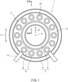
- FIG. 1 is a schematic diagram showing a combustor 2 of the gas turbine 1 according to Embodiment 1 when viewed from the downstream side in the flow direction.
- the combustor 2 is a combustor of the gas turbine 1 used as an aircraft engine.
- the combustor 2 mixes compressed air, supplied from a compressor, with fuel to generate a fuel-air mixture, and combusts the fuel-air mixture.
- the combustor 2 generates a high-temperature high-pressure combustion gas.
- the generated combustion gas is supplied to a turbine to drive the turbine.
- the combustor 2 is of an annular type formed in an annular shape surrounding the center axis X of the gas turbine 1.
- the combustor 2 may be of a type other than the annular type.
- the combustor 2 includes a casing 3.
- the casing 3 includes an annular outer casing 4 and an annular inner casing 5 which is concentrically located inside the outer casing 4.
- An annular internal space is defined by the outer casing 4 and the inner casing 5.
- a shell 6 is located in the annular internal space of the casing 3 and is a combustion liner that is concentric with the casing 3.
- the shell 6 includes an annular outer shell 7 and an annular inner shell 8 which is concentrically located inside the outer shell 7.
- An annular space surrounded by the outer shell 7 and the inner shell 8 is utilized as the combustion chamber 9.
- the outer shell 7 and the inner shell 8 extend linearly from the upstream side toward the downstream side.
- Fuel injectors 10 that inject the fuel into the combustion chamber 9 are located annularly along the combustion chamber 9 at the upstream side of the combustion chamber 9.
- the fuel injectors 10 are lined up at regular intervals in the circumferential direction C on a virtual circle that is concentric with the shell 6.
- Ignition plugs 11 are located at the shell 6 and generate sparks to ignite the fuel-air mixture in the combustion chamber 9 at the start of the gas turbine 1.
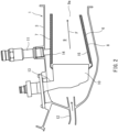
- FIG. 2 is a sectional view taken along line II-II of FIG. 1 showing the combustor 2.
- a side where the ignition plug 11 is located is an outside in the radial direction R of the gas turbine 1
- a side where the center axis X is located is an inside in the radial direction R of the gas turbine 1.
- a side where a diffuser 12 is located is the upstream side
- a side where the exhaust port 9a of the combustion chamber 9 is located is the downstream side.
- An inside of the shell 6 denotes an inside of the outer shell 7 in the radial direction and also denotes an outside of the inner shell 8 in the radial direction.
- the diffuser 12 is located at an upstream portion of the casing 3 and takes the compressed air, generated by the compressor, in the casing 3.
- the fuel injectors 10 are supported by a stem 13 fixed to the casing 3. Part of the compressed air which has been taken in the casing 3 is supplied to the fuel injectors 10 for combustion.
- the rest of the compressed air which has been taken in the casing 3 cools an outer surface of the shell 6, and part of the rest of the compressed air which has been taken in the casing is supplied as cooling air into the shell 6 through an opening 7b (see FIG. 4 ) of the shell 6.
- a substantially cylindrical outer panel group 14 as a liner is located inside the cylindrical outer shell 7 in the radial direction R.
- a substantially cylindrical outer panel group 14 as a liner is located outside the cylindrical inner shell 8 in the radial direction R.
- the outer panel group 14 and the inner panel group 15 define the combustion chamber 9. The gas combusted in the combustion chamber 9 is discharged toward the turbine through the exhaust port 9a defined by a downstream end of the outer shell 7 and a downstream end of the inner shell 8.
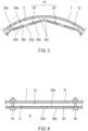
- FIG. 3 is a partial sectional view showing the combustor 2 of FIG. 2 when viewed in the flow direction F.
- FIG. 4 is a partial sectional view showing the combustor of FIG. 3 when viewed in the circumferential direction.
- the outer panel group 14 is an assembly of panels 20 which are adjacently lined up to have a substantially cylindrical shape.
- the inner panel group 15 (see FIG. 2 ) is also an assembly of panels which are adjacently lined up to have a substantially cylindrical shape.
- the outer panel group 14 will be mainly described.
- the panels 20 are made of a ceramic matrix composite (CMC).
- CMC ceramic matrix composite
- the panels 20 are located inside the shell 6 and lined up in the circumferential direction C. As shown in FIG. 4 , the panel 20 is attached to the outer shell 7 by fixtures 16 so as to be spaced apart from the outer shell 7.
- the fixture 16 includes a bolt and a nut.
- the configuration of the fixture 16 is not especially limited.
- the panel 20 includes an outer surface 20a and an inner surface 20b.
- the outer surface 20a is opposed to an inner peripheral surface 7a of the outer shell 7 so as to be spaced apart from the inner peripheral surface 7a.
- the inner surface 20b defines the combustion chamber 9 extending in the flow direction F from the upstream to downstream of the combustor 2.
- a space between the outer shell 7 and the panels 20 is utilized as a cooling air chamber S.
- FIG. 5 is a perspective view of the panel 20 of FIG. 5 .
- FIG. 6A is a diagram showing the panel 20 of FIG. 5 when viewed in a direction VIA (from the downstream side).
- FIG. 6B is a diagram showing the panel of FIG. 5 when viewed in a direction VIB (in the circumferential direction).
- a length L of the panel 20 in the flow direction F is longer than a width W of the panel 20 in the circumferential direction C.
- the panel 20 may extend from an upstream end of the combustion chamber 9 to a downstream end of the combustion chamber 9 in the flow direction F.
- the panel 20 may extend from an upstream end of an inner peripheral surface of the shell 6 to a downstream end of the inner peripheral surface of the shell 6 in the flow direction F.
- a neutral plane 20N between the outer surface 20a and inner surface 20b of the panel 20 has a planar shape.
- the panel 20 has a flat plate shape.
- each of the outer surface 20a and the inner surface 20b has a planar shape.
- the panel 20 may be such that: the neutral plane 20N has a planar shape; and each of the outer surface 20a and the inner surface 20b has a non-planar shape.
- the panel 20 includes attaching holes 20c into which the fixtures 16 are inserted.
- the panel 20 includes cooling holes 20d.
- the cooling holes 20d are lined up at intervals in the circumferential direction C of the panel 20.
- the number of cooling holes 20d does not have to be plural and may be one.
- the cooling holes 20d may be lined up in the flow direction F or may be lined up in both the circumferential direction C and the flow direction F. In the flow direction F, the cooling holes 20d are located between the attaching holes 20c at the upstream side and the attaching holes 20c at the downstream side.
- the panel 20 includes cutouts 20e located at end portions thereof in the circumferential direction C. When the cutouts 20e of a pair of panels 20 adjacent to each other are combined with each other, the cooling hole is formed.
- the outer shell 7 includes the opening 7b.
- Part of the compressed air in the casing 3 (see FIG. 2 ) is supplied as the cooling air through the opening 7b to the cooling air chamber S.
- the pressure in the cooling air chamber S is higher than the pressure in the combustion chamber 9. Therefore, the cooling air in the cooling air chamber S flows out through the cooling holes 20d of the panel 20 to the combustion chamber 9.
- the cooling air which has flowed out through the cooling holes 20d covers the inner surface 20b of the panel 20 to reduce a temperature increase of the inner surface 20b of the panel 20 which is caused by the combustion gas in the combustion chamber 9.
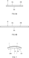
- FIG. 7 is a diagram showing a modified example of the panel 20 of FIG. 3 .
- a neutral plane 120N of a panel 120 of the modified example does not have to be a complete planar shape and may be a shape similar to the planar shape.
- assumed is a virtual circular arc V which extends through both ends of the neutral plane 120N of the panel 120 in the circumferential direction C and is concentric with the inner peripheral surface 7a of the outer shell 7 when viewed in the flow direction F.
- the neutral plane 120N of the panel 120 may have a curved surface shape which extends in the circumferential direction C and whose curvature is smaller than the curvature of the virtual circular arc V
- the panel 120 may have such a curved surface shape that a curvature radius R1 of the neutral plane 120N is smaller than a curvature radius R2 of the virtual circular arc V
- the panel 20 made of the ceramic matrix composite has a flat plate shape or a shape similar to a flat surface, restrictions by the shape of the panel 20 are reduced, and the stress of the panel 20 by the heat of the combustion chamber 9 can be reduced. Since the neutral plane 20N of the entire panel 20 has a planar shape, the stress of the panel 20 can be reduced by the simple shape. Since the length L of the panel 20 in the flow direction F is longer than the width W of the panel 20 in the circumferential direction C, the number of panels 20 is prevented from excessively increasing, and the productivity can be improved by simplifying the shape of the panel 20.
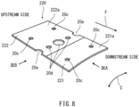
- FIG. 8 is a perspective view of a panel 220 of the combustor according to Embodiment 2.
- FIG. 9A is a diagram showing the panel 220 of FIG. 7 when viewed in a direction IXA (from the downstream side).
- FIG. 9B is a diagram showing the panel 220 of FIG. 7 when viewed in a direction IXB (in the circumferential direction).
- the same reference signs are used for the same components as in Embodiment 1, and explanations thereof are omitted.
- the panel 220 includes sections 221 and 222 lined up in the flow direction F. Specifically, the panel 220 includes a first section 221 and a second section 222.
- the panel 220 is formed by integral molding using the ceramic matrix composite.
- a length of the panel 220 in the flow direction F is longer than a width of the panel 220 in the the circumferential direction C.
- the panel 220 may extend from the upstream end of the combustion chamber 9 to the downstream end of the combustion chamber 9 in the flow direction F.
- the first section 221 is adjacent to the downstream side of the second section 222.
- the first section 221 is continuous with the second section 222.
- a neutral plane 221N between an outer surface 221a and inner surface 221b of the first section 221 has a circular-arc curved surface shape extending in the circumferential direction C.
- the first section 221 has an arch plate shape.
- a neutral plane 222N between an outer surface 222a and inner surface 222b of the second section 222 has a planar shape.
- the second section 222 has a flat plate shape.
- each of the outer surface 222a and inner surface 222b of the second section 222 has a planar shape.
- the second section 222 may be such that: the neutral plane 222N has a planar shape; and each of the outer surface 222a and the inner surface 222b has a non-planar shape.
- the second section 222 may have a curved surface shape which extends in the circumferential direction C and whose curvature is smaller than an average curvature of the neutral plane 221N of the first section 221.
- the thickness of the second section 222 is the same as the thickness of the first section 221 but may be different from the thickness of the first section 221.
- the thicknesses of the first section 221 and the second section 222 are constant but may be changed.
- the curvature of the neutral plane 221N of the first section 221 decreases as the neutral plane 221N approaches the second section 222 in the flow direction F. Conversely, the curvature of the neutral plane 221N of the first section 221 increases as the neutral plane 221N extends away from the second section 222 in the flow direction F.
- a change rate of the curvature of the first section 221 is constant in the flow direction F but may be changed.
- the first section 221 is located such that when viewed in the flow direction F, a circumferential middle portion of the first section 221 projects relative to the second section 222 outward in the radial direction R.
- the amount of projection of the first section 221 relative to the second section 222 outward in the radial direction R increases as the first section 221 extends away from the second section 222.
- a total region of the flat plate shape of the panel 220 is larger than a total region of the arch plate shape of the panel 220.
- a length of the total region of the flat plate shape of the panel 220 in the flow direction F is longer than a length of the total region of the arch plate shape of the panel 220 in the flow direction F.
- the second section 222 is larger than the first section 221.
- a length of the second section 222 in the flow direction F is longer than a length of the first section 221 in the flow direction F.
- both of the formation of the curved surface of the panel 220 and the stress reduction of the panel 220 can be realized by the combination of the simple shapes. Moreover, since the curvature of the neutral plane 221N of the first section 221 decreases as the neutral plane 221N approaches the second section 222 in the flow direction F, the panel 220 is prevented from having a distorted shape, and this contributes to the stress reduction of the panel 220. Since the other components are the same as those in Embodiment 1, explanations thereof are omitted.
- FIG. 10A is a diagram showing a modified example of the panel 220 of FIG. 9A and corresponding to FIG. 9A .
- FIG. 10B is a diagram showing the panel 220 of FIG. 10A and corresponding to FIG. 9B .
- the first section 221 may be located such that when viewed in the flow direction F, both circumferential end portions of the first section 221 project relative to the second section 222 inward in the radial direction R.
- the amount of projection of the first section 221 relative to the second section 222 inward in the radial direction R increases as the first section 221 extends away from the second section 222. According to this configuration, a uniform gap can be easily formed between the panel 220 and the shell 6 (see FIG. 2 ).
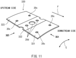
- FIG. 11 is a perspective view of a panel 320 of the combustor according to Embodiment 3.
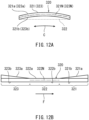
- FIG. 12A is a diagram showing the panel of FIG. 11 when viewed in a direction XIIA (from the downstream side).
- FIG. 12B is a diagram showing the panel of FIG. 11 when viewed in a direction XIIB (in the circumferential direction).
- the same reference signs are used for the same components as in Embodiment 1, and explanations thereof are omitted.
- the panel 320 includes sections 321 to 323 lined up in the flow direction F. Specifically, the panel 320 includes a first section 321, a second section 322, and a third section 323.
- the panel 220 is formed by integral molding using the ceramic matrix composite.
- a length of the panel 320 in the flow direction F is longer than a width of the panel 320 in the circumferential direction C.
- the panel 320 may extend from the upstream end of the combustion chamber 9 to the downstream end of the combustion chamber 9 in the flow direction F.
- the first section 321 is adjacent to the downstream side of the second section 322.
- the third section 323 is adjacent to the upstream side of the second section 322.
- the first section 321 and the third section 323 are continuous with the second section 322.
- Each of a neutral plane 321N of the first section 321 and a neutral plane 323N of the third section 323 has a circular-arc curved surface shape extending in the circumferential direction C.
- each of the first section 321 and the third section 323 has an arch plate shape.
- a neutral plane 322N between an outer surface 322a and inner surface 322b of the second section 322 has a planar shape.
- the second section 322 has a flat plate shape.
- the second section 322 may be such that: the neutral plane 322N has a planar shape; and each of the outer surface 322a and the inner surface 322b has a non-planar shape.
- the second section 322 may have a curved surface shape which extends in the circumferential direction C and whose curvature is smaller than an average curvature of the neutral plane 321N of the first section 321.
- Each of the thicknesses of the first section 321 and the third section 323 is the same as the thickness of the second section 322 but may be different from the thickness of the second section 322.
- Each of the thicknesses of the first to third sections 321 to 323 is constant but may be changed.
- the shape of the neutral plane 321N between an outer surface 321a and inner surface 321b of the first section 321 and the shape of the neutral plane 323N between an outer surface 323a and inner surface 323b of the third section 323 may be symmetric with respect to the second section 322.
- a length of the first section 321 in the flow direction F may be the same as a length of the third section 323 in the flow direction F but may be different from the length of the third section 323 in the flow direction F.
- the curvature of the neutral plane 321N of the first section 321 and the curvature of the neutral plane 323N of the third section 323 decrease as the neutral plane 321N and the neutral plane 323N approach the second section 322 in the flow direction F. Change rates of the curvatures of the first section 321 and the third section 323 are constant in the flow direction F but may be changed.
- the first section 321 may be located such that when viewed in the flow direction F, a circumferential middle portion of the first section 321 projects relative to the second section 322 outward in the radial direction R
- the third section 323 may be located such that when viewed in the flow direction F, a circumferential middle portion of the third section 323 projects relative to the second section 322 outward in the radial direction R.
- the first section 321 may be located such that when viewed in the flow direction F, both circumferential end portions of the first section 321 project relative to the second section 322 inward in the radial direction R
- the third section 323 may be located such that when viewed in the flow direction F, both circumferential end portions of the third section 323 project relative to the second section 322 inward in the radial direction R.
- a total region of the flat plate shape of the panel 320 is smaller than a total region of the arch plate shape of the panel 320.
- a length of the total region of the flat plate shape of the panel 220 in the flow direction F is shorter than a length of the total region of the arch plate shape of the panel 220 in the flow direction F.
- the second section 322 is larger than the total of the first section 321 and the third section 323.
- a length of the second section 322 in the flow direction F is longer than the total of a length of the first section 321 and a length of the third section 3233 in the flow direction F.
- both of the formation of the curved surface of the panel 320 and the stress reduction of the panel 320 can be realized by the combination of the simple shapes. Moreover, since the curvature of the neutral plane 321N of the first section 321 and the curvature of the neutral plane 323N of the third section 323 decrease as the neutral plane 321N and the neutral plane 323N approach the second section 322 in the flow direction F, the panel 320 is prevented from having a distorted shape, and this contributes to the stress reduction of the panel 320. Since the other components are the same as those in Embodiment 1, explanations thereof are omitted.
- FIG. 13A is a diagram showing a modified example of the panel 320 of FIG. 12A and corresponding to FIG. 12A .
- FIG. 13B is a diagram showing the panel 320 of FIG. 13A and corresponding to FIG. 12B .
- the first section 321 may be located such that when viewed in the flow direction F, both circumferential end portions of the first section 321 project relative to the second section 322 inward in the radial direction R.
- the third section 323 may be located such that when viewed in the flow direction F, both circumferential end portions of the first section 323 project relative to the second section 322 inward in the radial direction R.
- the amount of projection of the first section 321 relative to the second section 322 inward in the radial direction R and the amount of projection of the third section 323 relative to the second section 322 inward in the radial direction increase as the first section 321 and the third section 323 extend away from the second section 322. According to this configuration, a uniform gap can be easily formed between the panel 320 and the shell 6 (see FIG. 2 ).
Landscapes
- Engineering & Computer Science (AREA)
- Chemical & Material Sciences (AREA)
- Combustion & Propulsion (AREA)
- Mechanical Engineering (AREA)
- General Engineering & Computer Science (AREA)
- Ceramic Engineering (AREA)
- Turbine Rotor Nozzle Sealing (AREA)
Abstract
Description
- The present disclosure relates to a combustor panel made of a ceramic matrix composite and a gas turbine combustor including the combustor panel.
- To realize high-temperature high-pressure combustion for the purpose of the improvement of fuel efficiency, the improvement of heatproof temperatures of parts of combustors of gas turbines are required. Conventionally, a panel defining a combustion chamber of the combustor is made of metal and is cooled by air during the operation of the gas turbine.
-
PTL 1 discloses that the panel of the combustor is made of a ceramic matrix composite (CMC). The CMC is lighter than metal. Since the heatproof temperature of the CMC is high, the amount of cooling air can be reduced while realizing high-temperature high-pressure combustion. Therefore, when the panel is made of the CMC, the fuel efficiency of the gas turbine improves. - PTL 1: International Publication No.
2018/087878 - The CMC panel has a high heatproof temperature and is used at a position facing the combustion chamber. Therefore, high-temperature heat from the combustion chamber is input to an inner peripheral surface of the CMC panel. In the CMC panel, a thermal gradient from the inner peripheral surface toward an outer peripheral surface is generated. Therefore, in the CMC panel, thermal stress is generated by the heat of the combustion chamber. Thus, a reduction in the thermal stress of the CMC panel is required.
- An object of one aspect of the present disclosure is to reduce thermal stress generated in a CMC panel of a combustor of a gas turbine by heat of a combustion chamber.
- A panel of a combustor according to one aspect of the present disclosure is a panel of a combustor of a gas turbine, the panel being one of panels located inside a cylindrical shell of the combustor and lined up in a circumferential direction of the shell, the panel including a ceramic matrix composite. The panel includes: an outer surface that is opposed to an inner peripheral surface of the shell so as to be spaced apart from the inner peripheral surface of the shell; and an inner surface that defines a combustion chamber extending in a flow direction from an upstream side of the combustor to a downstream side of the combustor. At least part of a neutral plane between the outer surface and the inner surface has a planar shape or a curved surface shape which extends in the circumferential direction and whose curvature is smaller than a curvature of a virtual circular arc that is concentric with the inner peripheral surface of the shell.
- A combustor of a gas turbine according to one aspect of the present disclosure includes: a cylindrical shell; and panels which are the above panels, are located inside the shell, are located in a circumferential direction, and are made of a ceramic matrix composite.
- According to one aspect of the present disclosure, at least part of the panel made of the ceramic matrix composite has a flat plate shape or a shape similar to a flat surface. Therefore, restrictions by the shape of the panel are reduced, and thermal stress generated in the panel by the heat of the combustion chamber can be reduced.
-
-
FIG. 1 is a sectional view showing a combustor of a gas turbine according toEmbodiment 1 when viewed from a downstream side in a flow direction. -
FIG. 2 is a sectional view taken along line II-II ofFIG. 1 showing the combustor. -
FIG. 3 is a partial sectional view showing the combustor ofFIG. 2 when viewed in the flow direction. -
FIG. 4 is a partial sectional view showing the combustor ofFIG. 3 when viewed in a circumferential direction. -
FIG. 5 is a perspective view of the panel ofFIG. 4 . -
FIG. 6A is a diagram showing the panel ofFIG. 5 when viewed in a direction VIA (from the downstream side). -
FIG. 6B is a diagram showing the panel ofFIG. 5 when viewed in a direction VIB (in the circumferential direction). -
FIG. 7 is a diagram showing a modified example of the panel ofFIG. 3 . -
FIG. 8 is a perspective view of the panel of the combustor according to Embodiment 2. -
FIG. 9A is a diagram showing the panel ofFIG. 8 when viewed in a direction IXA (from the downstream side). -
FIG. 9B is a diagram showing the panel ofFIG. 8 when viewed in a direction IXB (in the circumferential direction). -
FIG. 10A is a diagram showing a modified example of the panel ofFIG. 9A and corresponding toFIG. 9A . -
FIG. 10B is a diagram showing the panel ofFIG. 10A and corresponding toFIG. 9B . -
FIG. 11 is a perspective view of the panel of the combustor according to Embodiment 3. -
FIG. 12A is a diagram showing the panel ofFIG. 11 when viewed in a direction XIIA (from the downstream side). -
FIG. 12B is a diagram showing the panel ofFIG. 11 when viewed in a direction XIIB (in the circumferential direction). -
FIG. 13A is a diagram showing a modified example of the panel ofFIG. 12A and corresponding toFIG. 12A . -
FIG. 13B is a diagram showing the panel ofFIG. 13A and corresponding toFIG. 12B . - Hereinafter, embodiments will be described with reference to the drawings. In the following description, a direction orthogonal to a center axis X of a
gas turbine 1 is referred to as a radial direction R, and a direction around the center axis X is referred to as a circumferential direction C. Moreover, in a flow direction F in acombustion chamber 9, a side where afuel injector 10 is located is referred to as an upstream side, and a side where anexhaust port 9a is located is referred to as a downstream side. -
FIG. 1 is a schematic diagram showing acombustor 2 of thegas turbine 1 according toEmbodiment 1 when viewed from the downstream side in the flow direction. Thecombustor 2 is a combustor of thegas turbine 1 used as an aircraft engine. Thecombustor 2 mixes compressed air, supplied from a compressor, with fuel to generate a fuel-air mixture, and combusts the fuel-air mixture. Thus, thecombustor 2 generates a high-temperature high-pressure combustion gas. The generated combustion gas is supplied to a turbine to drive the turbine. - For example, the
combustor 2 is of an annular type formed in an annular shape surrounding the center axis X of thegas turbine 1. Thecombustor 2 may be of a type other than the annular type. Thecombustor 2 includes acasing 3. Thecasing 3 includes an annularouter casing 4 and an annularinner casing 5 which is concentrically located inside theouter casing 4. An annular internal space is defined by theouter casing 4 and theinner casing 5. Ashell 6 is located in the annular internal space of thecasing 3 and is a combustion liner that is concentric with thecasing 3. Theshell 6 includes an annularouter shell 7 and an annularinner shell 8 which is concentrically located inside theouter shell 7. An annular space surrounded by theouter shell 7 and theinner shell 8 is utilized as thecombustion chamber 9. In a section viewed in the circumferential direction C, theouter shell 7 and theinner shell 8 extend linearly from the upstream side toward the downstream side. -
Fuel injectors 10 that inject the fuel into thecombustion chamber 9 are located annularly along thecombustion chamber 9 at the upstream side of thecombustion chamber 9. Thefuel injectors 10 are lined up at regular intervals in the circumferential direction C on a virtual circle that is concentric with theshell 6. Ignition plugs 11 are located at theshell 6 and generate sparks to ignite the fuel-air mixture in thecombustion chamber 9 at the start of thegas turbine 1. -
FIG. 2 is a sectional view taken along line II-II ofFIG. 1 showing thecombustor 2. InFIG. 2 , a side where theignition plug 11 is located is an outside in the radial direction R of thegas turbine 1, and a side where the center axis X is located is an inside in the radial direction R of thegas turbine 1. Moreover, a side where adiffuser 12 is located is the upstream side, and a side where theexhaust port 9a of thecombustion chamber 9 is located is the downstream side. An inside of theshell 6 denotes an inside of theouter shell 7 in the radial direction and also denotes an outside of theinner shell 8 in the radial direction. - As shown in
FIG. 2 , thediffuser 12 is located at an upstream portion of thecasing 3 and takes the compressed air, generated by the compressor, in thecasing 3. Thefuel injectors 10 are supported by astem 13 fixed to thecasing 3. Part of the compressed air which has been taken in thecasing 3 is supplied to thefuel injectors 10 for combustion. The rest of the compressed air which has been taken in thecasing 3 cools an outer surface of theshell 6, and part of the rest of the compressed air which has been taken in the casing is supplied as cooling air into theshell 6 through anopening 7b (seeFIG. 4 ) of theshell 6. - A substantially cylindrical
outer panel group 14 as a liner is located inside the cylindricalouter shell 7 in the radial direction R. A substantially cylindricalouter panel group 14 as a liner is located outside the cylindricalinner shell 8 in the radial direction R. Theouter panel group 14 and theinner panel group 15 define thecombustion chamber 9. The gas combusted in thecombustion chamber 9 is discharged toward the turbine through theexhaust port 9a defined by a downstream end of theouter shell 7 and a downstream end of theinner shell 8. -
FIG. 3 is a partial sectional view showing thecombustor 2 ofFIG. 2 when viewed in the flow direction F.FIG. 4 is a partial sectional view showing the combustor ofFIG. 3 when viewed in the circumferential direction. As shown inFIG. 3 , theouter panel group 14 is an assembly ofpanels 20 which are adjacently lined up to have a substantially cylindrical shape. The inner panel group 15 (seeFIG. 2 ) is also an assembly of panels which are adjacently lined up to have a substantially cylindrical shape. Hereinafter, theouter panel group 14 will be mainly described. - The
panels 20 are made of a ceramic matrix composite (CMC). Thepanels 20 are located inside theshell 6 and lined up in the circumferential direction C. As shown inFIG. 4 , thepanel 20 is attached to theouter shell 7 byfixtures 16 so as to be spaced apart from theouter shell 7. As one example, thefixture 16 includes a bolt and a nut. However, the configuration of thefixture 16 is not especially limited. Thepanel 20 includes anouter surface 20a and aninner surface 20b. Theouter surface 20a is opposed to an innerperipheral surface 7a of theouter shell 7 so as to be spaced apart from the innerperipheral surface 7a. Theinner surface 20b defines thecombustion chamber 9 extending in the flow direction F from the upstream to downstream of thecombustor 2. A space between theouter shell 7 and thepanels 20 is utilized as a cooling air chamber S. -
FIG. 5 is a perspective view of thepanel 20 ofFIG. 5 .FIG. 6A is a diagram showing thepanel 20 ofFIG. 5 when viewed in a direction VIA (from the downstream side).FIG. 6B is a diagram showing the panel ofFIG. 5 when viewed in a direction VIB (in the circumferential direction). As shown inFIGS. 5 ,6A, and 6B , a length L of thepanel 20 in the flow direction F is longer than a width W of thepanel 20 in the circumferential direction C. For example, thepanel 20 may extend from an upstream end of thecombustion chamber 9 to a downstream end of thecombustion chamber 9 in the flow direction F. Thepanel 20 may extend from an upstream end of an inner peripheral surface of theshell 6 to a downstream end of the inner peripheral surface of theshell 6 in the flow direction F. - A
neutral plane 20N between theouter surface 20a andinner surface 20b of thepanel 20 has a planar shape. In the present embodiment, thepanel 20 has a flat plate shape. To be specific, each of theouter surface 20a and theinner surface 20b has a planar shape. Thepanel 20 may be such that: theneutral plane 20N has a planar shape; and each of theouter surface 20a and theinner surface 20b has a non-planar shape. - The
panel 20 includes attachingholes 20c into which thefixtures 16 are inserted. Thepanel 20 includescooling holes 20d. The cooling holes 20d are lined up at intervals in the circumferential direction C of thepanel 20. The number ofcooling holes 20d does not have to be plural and may be one. The cooling holes 20d may be lined up in the flow direction F or may be lined up in both the circumferential direction C and the flow direction F. In the flow direction F, thecooling holes 20d are located between the attachingholes 20c at the upstream side and the attachingholes 20c at the downstream side. Thepanel 20 includescutouts 20e located at end portions thereof in the circumferential direction C. When thecutouts 20e of a pair ofpanels 20 adjacent to each other are combined with each other, the cooling hole is formed. - Referring back to
FIG. 4 , theouter shell 7 includes theopening 7b. Part of the compressed air in the casing 3 (seeFIG. 2 ) is supplied as the cooling air through theopening 7b to the cooling air chamber S. The pressure in the cooling air chamber S is higher than the pressure in thecombustion chamber 9. Therefore, the cooling air in the cooling air chamber S flows out through thecooling holes 20d of thepanel 20 to thecombustion chamber 9. The cooling air which has flowed out through the cooling holes 20d covers theinner surface 20b of thepanel 20 to reduce a temperature increase of theinner surface 20b of thepanel 20 which is caused by the combustion gas in thecombustion chamber 9. -
FIG. 7 is a diagram showing a modified example of thepanel 20 ofFIG. 3 . As shown inFIG. 7 , aneutral plane 120N of apanel 120 of the modified example does not have to be a complete planar shape and may be a shape similar to the planar shape. For example, assumed is a virtual circular arc V which extends through both ends of theneutral plane 120N of thepanel 120 in the circumferential direction C and is concentric with the innerperipheral surface 7a of theouter shell 7 when viewed in the flow direction F. Theneutral plane 120N of thepanel 120 may have a curved surface shape which extends in the circumferential direction C and whose curvature is smaller than the curvature of the virtual circular arc V To be specific, thepanel 120 may have such a curved surface shape that a curvature radius R1 of theneutral plane 120N is smaller than a curvature radius R2 of the virtual circular arc V - According to the above-described configuration, since the
panel 20 made of the ceramic matrix composite has a flat plate shape or a shape similar to a flat surface, restrictions by the shape of thepanel 20 are reduced, and the stress of thepanel 20 by the heat of thecombustion chamber 9 can be reduced. Since theneutral plane 20N of theentire panel 20 has a planar shape, the stress of thepanel 20 can be reduced by the simple shape. Since the length L of thepanel 20 in the flow direction F is longer than the width W of thepanel 20 in the circumferential direction C, the number ofpanels 20 is prevented from excessively increasing, and the productivity can be improved by simplifying the shape of thepanel 20. -
FIG. 8 is a perspective view of apanel 220 of the combustor according toEmbodiment 2.FIG. 9A is a diagram showing thepanel 220 ofFIG. 7 when viewed in a direction IXA (from the downstream side).FIG. 9B is a diagram showing thepanel 220 ofFIG. 7 when viewed in a direction IXB (in the circumferential direction). The same reference signs are used for the same components as inEmbodiment 1, and explanations thereof are omitted. As shown inFIGS. 7 , 8A, and 8B, thepanel 220 includessections panel 220 includes afirst section 221 and asecond section 222. Thepanel 220 is formed by integral molding using the ceramic matrix composite. A length of thepanel 220 in the flow direction F is longer than a width of thepanel 220 in the the circumferential direction C. For example, thepanel 220 may extend from the upstream end of thecombustion chamber 9 to the downstream end of thecombustion chamber 9 in the flow direction F. - The
first section 221 is adjacent to the downstream side of thesecond section 222. Thefirst section 221 is continuous with thesecond section 222. Aneutral plane 221N between anouter surface 221a andinner surface 221b of thefirst section 221 has a circular-arc curved surface shape extending in the circumferential direction C. In the present embodiment, thefirst section 221 has an arch plate shape. - A
neutral plane 222N between anouter surface 222a andinner surface 222b of thesecond section 222 has a planar shape. In the present embodiment, thesecond section 222 has a flat plate shape. To be specific, each of theouter surface 222a andinner surface 222b of thesecond section 222 has a planar shape. Thesecond section 222 may be such that: theneutral plane 222N has a planar shape; and each of theouter surface 222a and theinner surface 222b has a non-planar shape. - Moreover, the
second section 222 may have a curved surface shape which extends in the circumferential direction C and whose curvature is smaller than an average curvature of theneutral plane 221N of thefirst section 221. The thickness of thesecond section 222 is the same as the thickness of thefirst section 221 but may be different from the thickness of thefirst section 221. The thicknesses of thefirst section 221 and thesecond section 222 are constant but may be changed. - The curvature of the
neutral plane 221N of thefirst section 221 decreases as theneutral plane 221N approaches thesecond section 222 in the flow direction F. Conversely, the curvature of theneutral plane 221N of thefirst section 221 increases as theneutral plane 221N extends away from thesecond section 222 in the flow direction F. A change rate of the curvature of thefirst section 221 is constant in the flow direction F but may be changed. - As shown in
FIG. 9A , thefirst section 221 is located such that when viewed in the flow direction F, a circumferential middle portion of thefirst section 221 projects relative to thesecond section 222 outward in the radial direction R. The amount of projection of thefirst section 221 relative to thesecond section 222 outward in the radial direction R increases as thefirst section 221 extends away from thesecond section 222. - A total region of the flat plate shape of the
panel 220 is larger than a total region of the arch plate shape of thepanel 220. A length of the total region of the flat plate shape of thepanel 220 in the flow direction F is longer than a length of the total region of the arch plate shape of thepanel 220 in the flow direction F. In the present embodiment, thesecond section 222 is larger than thefirst section 221. A length of thesecond section 222 in the flow direction F is longer than a length of thefirst section 221 in the flow direction F. - According to the above configuration, both of the formation of the curved surface of the
panel 220 and the stress reduction of thepanel 220 can be realized by the combination of the simple shapes. Moreover, since the curvature of theneutral plane 221N of thefirst section 221 decreases as theneutral plane 221N approaches thesecond section 222 in the flow direction F, thepanel 220 is prevented from having a distorted shape, and this contributes to the stress reduction of thepanel 220. Since the other components are the same as those inEmbodiment 1, explanations thereof are omitted. -
FIG. 10A is a diagram showing a modified example of thepanel 220 ofFIG. 9A and corresponding toFIG. 9A .FIG. 10B is a diagram showing thepanel 220 ofFIG. 10A and corresponding toFIG. 9B . As shown inFIGS. 10A and 10B , thefirst section 221 may be located such that when viewed in the flow direction F, both circumferential end portions of thefirst section 221 project relative to thesecond section 222 inward in the radial direction R. The amount of projection of thefirst section 221 relative to thesecond section 222 inward in the radial direction R increases as thefirst section 221 extends away from thesecond section 222. According to this configuration, a uniform gap can be easily formed between thepanel 220 and the shell 6 (seeFIG. 2 ). -
FIG. 11 is a perspective view of apanel 320 of the combustor according toEmbodiment 3.FIG. 12A is a diagram showing the panel ofFIG. 11 when viewed in a direction XIIA (from the downstream side).FIG. 12B is a diagram showing the panel ofFIG. 11 when viewed in a direction XIIB (in the circumferential direction). The same reference signs are used for the same components as inEmbodiment 1, and explanations thereof are omitted. As shown inFIGS. 11 ,12A, and 12B , thepanel 320 includessections 321 to 323 lined up in the flow direction F. Specifically, thepanel 320 includes afirst section 321, asecond section 322, and athird section 323. Thepanel 220 is formed by integral molding using the ceramic matrix composite. A length of thepanel 320 in the flow direction F is longer than a width of thepanel 320 in the circumferential direction C. For example, thepanel 320 may extend from the upstream end of thecombustion chamber 9 to the downstream end of thecombustion chamber 9 in the flow direction F. - The
first section 321 is adjacent to the downstream side of thesecond section 322. Thethird section 323 is adjacent to the upstream side of thesecond section 322. Thefirst section 321 and thethird section 323 are continuous with thesecond section 322. Each of aneutral plane 321N of thefirst section 321 and aneutral plane 323N of thethird section 323 has a circular-arc curved surface shape extending in the circumferential direction C. In the present embodiment, each of thefirst section 321 and thethird section 323 has an arch plate shape. - A
neutral plane 322N between anouter surface 322a andinner surface 322b of thesecond section 322 has a planar shape. In the present embodiment, thesecond section 322 has a flat plate shape. Thesecond section 322 may be such that: theneutral plane 322N has a planar shape; and each of theouter surface 322a and theinner surface 322b has a non-planar shape. Moreover, thesecond section 322 may have a curved surface shape which extends in the circumferential direction C and whose curvature is smaller than an average curvature of theneutral plane 321N of thefirst section 321. Each of the thicknesses of thefirst section 321 and thethird section 323 is the same as the thickness of thesecond section 322 but may be different from the thickness of thesecond section 322. Each of the thicknesses of the first tothird sections 321 to 323 is constant but may be changed. - The shape of the
neutral plane 321N between anouter surface 321a andinner surface 321b of thefirst section 321 and the shape of theneutral plane 323N between anouter surface 323a andinner surface 323b of thethird section 323 may be symmetric with respect to thesecond section 322. A length of thefirst section 321 in the flow direction F may be the same as a length of thethird section 323 in the flow direction F but may be different from the length of thethird section 323 in the flow direction F. The curvature of theneutral plane 321N of thefirst section 321 and the curvature of theneutral plane 323N of thethird section 323 decrease as theneutral plane 321N and theneutral plane 323N approach thesecond section 322 in the flow direction F. Change rates of the curvatures of thefirst section 321 and thethird section 323 are constant in the flow direction F but may be changed. - As shown in
FIG. 12A , thefirst section 321 may be located such that when viewed in the flow direction F, a circumferential middle portion of thefirst section 321 projects relative to thesecond section 322 outward in the radial direction R, and thethird section 323 may be located such that when viewed in the flow direction F, a circumferential middle portion of thethird section 323 projects relative to thesecond section 322 outward in the radial direction R. Or, thefirst section 321 may be located such that when viewed in the flow direction F, both circumferential end portions of thefirst section 321 project relative to thesecond section 322 inward in the radial direction R, and thethird section 323 may be located such that when viewed in the flow direction F, both circumferential end portions of thethird section 323 project relative to thesecond section 322 inward in the radial direction R. - A total region of the flat plate shape of the
panel 320 is smaller than a total region of the arch plate shape of thepanel 320. A length of the total region of the flat plate shape of thepanel 220 in the flow direction F is shorter than a length of the total region of the arch plate shape of thepanel 220 in the flow direction F. In the present embodiment, thesecond section 322 is larger than the total of thefirst section 321 and thethird section 323. A length of thesecond section 322 in the flow direction F is longer than the total of a length of thefirst section 321 and a length of the third section 3233 in the flow direction F. - According to the above configuration, both of the formation of the curved surface of the
panel 320 and the stress reduction of thepanel 320 can be realized by the combination of the simple shapes. Moreover, since the curvature of theneutral plane 321N of thefirst section 321 and the curvature of theneutral plane 323N of thethird section 323 decrease as theneutral plane 321N and theneutral plane 323N approach thesecond section 322 in the flow direction F, thepanel 320 is prevented from having a distorted shape, and this contributes to the stress reduction of thepanel 320. Since the other components are the same as those inEmbodiment 1, explanations thereof are omitted. -
FIG. 13A is a diagram showing a modified example of thepanel 320 ofFIG. 12A and corresponding toFIG. 12A .FIG. 13B is a diagram showing thepanel 320 ofFIG. 13A and corresponding toFIG. 12B . As shown inFIGS. 13A and 13B , thefirst section 321 may be located such that when viewed in the flow direction F, both circumferential end portions of thefirst section 321 project relative to thesecond section 322 inward in the radial direction R. Similarly, thethird section 323 may be located such that when viewed in the flow direction F, both circumferential end portions of thefirst section 323 project relative to thesecond section 322 inward in the radial direction R. The amount of projection of thefirst section 321 relative to thesecond section 322 inward in the radial direction R and the amount of projection of thethird section 323 relative to thesecond section 322 inward in the radial direction increase as thefirst section 321 and thethird section 323 extend away from thesecond section 322. According to this configuration, a uniform gap can be easily formed between thepanel 320 and the shell 6 (seeFIG. 2 ). - The foregoing has described the embodiments as examples of the technology disclosed in the present application. However, the technology in the present disclosure is not limited to these and is applicable to embodiments in which modifications, replacements, additions, omissions, and the like have been suitably made. Moreover, a new embodiment may be prepared by combining the components described in the above embodiments. For example, some of components or methods in one embodiment may be applied to another embodiment. Some components in an embodiment may be separated from the other components in the embodiment and arbitrarily extracted. Furthermore, the components shown in the attached drawings and the detailed explanations include not only components essential to solve the problems but also components for exemplifying the above technology and not essential to solve the problems.
-
- 1 gas turbine
- 2 combustor
- 6 shell
- 7 outer shell
- 8 inner shell
- 9 combustion chamber
- 14 outer panel group
- 15 inner panel group
- 16 fixture
- 20, 120, 220, 320 panel
- 20a, 221a, 222a, 321a, 322a, 323a outer surface
- 20b, 221b, 222b, 321b, 322b, 323b inner surface
- 20d cooling hole
- 20N, 120N, 221N, 222N, 321N, 322N, 323N neutral plane
- 221, 321 first section
- 222, 322 second section
- 323 third section
- C circumferential direction
- F flow direction
- R radial direction
- S cooling air chamber
- X center axis
Claims (10)
- A panel of a combustor of a gas turbine, the panel being one of panels located inside a cylindrical shell of the combustor and lined up in a circumferential direction, the panel including a ceramic matrix composite,the panel comprising:an outer surface that is opposed to an inner peripheral surface of the shell so as to be spaced apart from the inner peripheral surface of the shell; andan inner surface that defines a combustion chamber extending in a flow direction from an upstream side of the combustor to a downstream side of the combustor, wherein:at least part of a neutral plane between the outer surface and the inner surface hasa planar shape ora curved surface shape which extends in the circumferential direction and whose curvature is smaller than a curvature of a virtual circular arc that is concentric with the inner peripheral surface of the shell.
- The panel according to claim 1, further comprising sections lined up in the flow direction and including a first section and a second section, wherein:a neutral plane of the first section has a curved surface shape extending in the circumferential direction; anda neutral plane of the second section hasa planar shape ora curved surface shape which extends in the circumferential direction and whose curvature is smaller than an average curvature of the neutral plane of the first section.
- The panel according to claim 2, wherein the first section has an arch plate shape, and the second section has a flat plate shape.
- The panel according to claim 2 or 3, wherein:the sections further include a third section;the sections are adjacent to each other in the flow direction in order of the first section, the second section, and the third section;each of the first section and the third section has an arch plate shape; andthe second section has a flat plate shape.
- The panel according to any one of claims 2 to 4, wherein:the first section is continuous with the second section while being adjacent to the second section in the flow direction; anda curvature of the neutral plane of the first section decreases as the neutral plane of the first section approaches the second section in the flow direction.
- The panel according to any one of claims 2 to 5, wherein the second section is located upstream of the first section in the flow direction.
- The panel according to claim 1, wherein the at least part of the neutral plane includes the neutral plane of the entire panel.
- The panel according to any one of claims 1 to 7, wherein a length of the panel in the flow direction is longer than a width of the panel in the circumferential direction.
- A combustor of a gas turbine,
the combustor comprising:a cylindrical shell; andpanels located inside the shell, lined up in a circumferential direction, and including a ceramic matrix composite, at least one of the panels being the panel according to any one of claims 1 to 8. - The combustor according to claim 9, wherein the panels extend in the flow direction from an upstream end of the combustion chamber to a downstream end of the combustor chamber.
Applications Claiming Priority (2)
| Application Number | Priority Date | Filing Date | Title |
|---|---|---|---|
| JP2021211922A JP7780333B2 (en) | 2021-12-27 | 2021-12-27 | Combustor panel and gas turbine combustor equipped with same |
| PCT/JP2022/047420 WO2023127691A1 (en) | 2021-12-27 | 2022-12-22 | Combustor panel, and gas turbine combustor comprising same |
Publications (2)
| Publication Number | Publication Date |
|---|---|
| EP4459188A1 true EP4459188A1 (en) | 2024-11-06 |
| EP4459188A4 EP4459188A4 (en) | 2025-12-24 |
Family
ID=86999103
Family Applications (1)
| Application Number | Title | Priority Date | Filing Date |
|---|---|---|---|
| EP22915914.0A Pending EP4459188A4 (en) | 2021-12-27 | 2022-12-22 | Combustion chamber plate and gas turbine combustion chamber with it |
Country Status (4)
| Country | Link |
|---|---|
| US (1) | US12571537B2 (en) |
| EP (1) | EP4459188A4 (en) |
| JP (1) | JP7780333B2 (en) |
| WO (1) | WO2023127691A1 (en) |
Family Cites Families (32)
| Publication number | Priority date | Publication date | Assignee | Title |
|---|---|---|---|---|
| JPS5857658B2 (en) * | 1980-04-02 | 1983-12-21 | 工業技術院長 | Heat shielding structure for walls exposed to high heat using ceramics |
| US4422300A (en) | 1981-12-14 | 1983-12-27 | United Technologies Corporation | Prestressed combustor liner for gas turbine engine |
| US4567730A (en) * | 1983-10-03 | 1986-02-04 | General Electric Company | Shielded combustor |
| US4688310A (en) * | 1983-12-19 | 1987-08-25 | General Electric Company | Fabricated liner article and method |
| US4838030A (en) * | 1987-08-06 | 1989-06-13 | Avco Corporation | Combustion chamber liner having failure activated cooling and dectection system |
| US4838031A (en) * | 1987-08-06 | 1989-06-13 | Avco Corporation | Internally cooled combustion chamber liner |
| US5333443A (en) * | 1993-02-08 | 1994-08-02 | General Electric Company | Seal assembly |
| EP0943867B1 (en) | 1998-03-17 | 2002-12-18 | ALSTOM (Switzerland) Ltd | Ceramic lining for a combustor |
| DE19915049A1 (en) * | 1999-04-01 | 2000-10-05 | Abb Alstom Power Ch Ag | Heat shield for a gas turbine |
| EP1482246A1 (en) * | 2003-05-30 | 2004-12-01 | Siemens Aktiengesellschaft | Combustion chamber |
| JP4129518B2 (en) | 2005-02-07 | 2008-08-06 | 川崎重工業株式会社 | Gas turbine combustor wall structure |
| US8596071B2 (en) * | 2006-05-05 | 2013-12-03 | General Electric Company | Method and apparatus for assembling a gas turbine engine |
| FR2929690B1 (en) | 2008-04-03 | 2012-08-17 | Snecma Propulsion Solide | COMBUSTION CHAMBER SECTORIZED IN CMC FOR GAS TURBINE |
| FR2929689B1 (en) * | 2008-04-03 | 2013-04-12 | Snecma Propulsion Solide | GAS TURBINE COMBUSTION CHAMBER WITH SECTORIZED INTERNAL AND EXTERNAL WALLS |
| JP5910008B2 (en) | 2011-11-11 | 2016-04-27 | 株式会社Ihi | Combustor liner |
| DE102012015449A1 (en) * | 2012-08-03 | 2014-02-20 | Rolls-Royce Deutschland Ltd & Co Kg | Gas turbine combustion chamber with mixed air openings and air guide elements in a modular design |
| EP2965010B1 (en) | 2013-03-05 | 2018-10-17 | Rolls-Royce Corporation | Dual-wall impingement, convection, effusion combustor tile |
| EP3084303B1 (en) * | 2013-12-19 | 2022-01-26 | Raytheon Technologies Corporation | Thermal mechanical dimple array for a combustor wall assembly |
| GB201322838D0 (en) * | 2013-12-23 | 2014-02-12 | Rolls Royce Plc | A combustion chamber |
| US9517507B2 (en) * | 2014-07-17 | 2016-12-13 | Pratt & Whitney Canada Corp. | Method of shaping green part and manufacturing method using same |
| US11619387B2 (en) * | 2015-07-28 | 2023-04-04 | Rolls-Royce Corporation | Liner for a combustor of a gas turbine engine with metallic corrugated member |
| US10584880B2 (en) * | 2016-03-25 | 2020-03-10 | General Electric Company | Mounting of integrated combustor nozzles in a segmented annular combustion system |
| US11002190B2 (en) * | 2016-03-25 | 2021-05-11 | General Electric Company | Segmented annular combustion system |
| GB201610122D0 (en) * | 2016-06-10 | 2016-07-27 | Rolls Royce Plc | A combustion chamber |
| US11067277B2 (en) * | 2016-10-07 | 2021-07-20 | General Electric Company | Component assembly for a gas turbine engine |
| US10830433B2 (en) * | 2016-11-10 | 2020-11-10 | Raytheon Technologies Corporation | Axial non-linear interface for combustor liner panels in a gas turbine combustor |
| WO2018087878A1 (en) | 2016-11-11 | 2018-05-17 | 川崎重工業株式会社 | Combustor liner |
| US11035572B2 (en) * | 2018-06-28 | 2021-06-15 | Raytheon Technologies Corporation | Heat shield panel manufacturing process |
| US20200300469A1 (en) * | 2019-03-19 | 2020-09-24 | United Technologies Corporation | Aerodynamic component for a gas turbine engine |
| GB201903879D0 (en) * | 2019-03-21 | 2019-05-08 | Rolls Royce Plc | A combustor tile for a combustor of a gas turbine engine |
| US11536454B2 (en) * | 2019-05-09 | 2022-12-27 | Pratt & Whitney Canada Corp. | Combustor wall assembly for gas turbine engine |
| US11466855B2 (en) * | 2020-04-17 | 2022-10-11 | Rolls-Royce North American Technologies Inc. | Gas turbine engine combustor with ceramic matrix composite liner |
-
2021
- 2021-12-27 JP JP2021211922A patent/JP7780333B2/en active Active
-
2022
- 2022-12-22 EP EP22915914.0A patent/EP4459188A4/en active Pending
- 2022-12-22 US US18/724,248 patent/US12571537B2/en active Active
- 2022-12-22 WO PCT/JP2022/047420 patent/WO2023127691A1/en not_active Ceased
Also Published As
| Publication number | Publication date |
|---|---|
| US20250060104A1 (en) | 2025-02-20 |
| JP2023096286A (en) | 2023-07-07 |
| EP4459188A4 (en) | 2025-12-24 |
| US12571537B2 (en) | 2026-03-10 |
| WO2023127691A1 (en) | 2023-07-06 |
| JP7780333B2 (en) | 2025-12-04 |
Similar Documents
| Publication | Publication Date | Title |
|---|---|---|
| CN108019779B (en) | Multi-point injection micro-hybrid fuel nozzle assembly | |
| CN111578311B (en) | Fuel nozzle assembly | |
| US9423130B2 (en) | Reverse flow ceramic matrix composite combustor | |
| US8261555B2 (en) | Injection nozzle for a turbomachine | |
| US9021812B2 (en) | Combustor dome and heat-shield assembly | |
| CN104061595B (en) | Continuous burning bushing for the burner of combustion gas turbine | |
| US8544277B2 (en) | Turbulated aft-end liner assembly and cooling method | |
| US8756935B2 (en) | Gas turbine engine combustion chamber comprising CMC deflectors | |
| EP2864707B1 (en) | Turbine engine combustor wall with non-uniform distribution of effusion apertures | |
| US10584638B2 (en) | Turbine nozzle cooling with panel fuel injector | |
| EP2211105A2 (en) | Turbulated combustor aft-end liner assembly and related cooling method | |
| JP2009085222A (en) | Rear end liner assembly with turbulator and cooling method thereof | |
| EP2438357B1 (en) | Burner | |
| CN108006696A (en) | burner assembly and burner | |
| US20250060104A1 (en) | Combustor panel and gas turbine combustor including same | |
| CN111829013A (en) | Transition pipe for gas turbine assembly and gas turbine assembly comprising same | |
| US12540732B2 (en) | Combustor of gas turbine | |
| EP4641092A1 (en) | Combustor for gas turbines | |
| EP4641087A1 (en) | Combustor for gas turbine | |
| US20250362021A1 (en) | Combustor of gas turbine |
Legal Events
| Date | Code | Title | Description |
|---|---|---|---|
| STAA | Information on the status of an ep patent application or granted ep patent |
Free format text: STATUS: THE INTERNATIONAL PUBLICATION HAS BEEN MADE |
|
| PUAI | Public reference made under article 153(3) epc to a published international application that has entered the european phase |
Free format text: ORIGINAL CODE: 0009012 |
|
| STAA | Information on the status of an ep patent application or granted ep patent |
Free format text: STATUS: REQUEST FOR EXAMINATION WAS MADE |
|
| 17P | Request for examination filed |
Effective date: 20240704 |
|
| AK | Designated contracting states |
Kind code of ref document: A1 Designated state(s): AL AT BE BG CH CY CZ DE DK EE ES FI FR GB GR HR HU IE IS IT LI LT LU LV MC ME MK MT NL NO PL PT RO RS SE SI SK SM TR |
|
| DAV | Request for validation of the european patent (deleted) | ||
| DAX | Request for extension of the european patent (deleted) | ||
| A4 | Supplementary search report drawn up and despatched |
Effective date: 20251121 |
|
| RIC1 | Information provided on ipc code assigned before grant |
Ipc: F23R 3/42 20060101AFI20251117BHEP Ipc: F23R 3/00 20060101ALI20251117BHEP |