EP4459156A1 - Gearbox assembly for an aircraft propulsion system - Google Patents
Gearbox assembly for an aircraft propulsion system Download PDFInfo
- Publication number
- EP4459156A1 EP4459156A1 EP24173851.7A EP24173851A EP4459156A1 EP 4459156 A1 EP4459156 A1 EP 4459156A1 EP 24173851 A EP24173851 A EP 24173851A EP 4459156 A1 EP4459156 A1 EP 4459156A1
- Authority
- EP
- European Patent Office
- Prior art keywords
- gear
- lateral
- assembly
- pattern
- planet
- Prior art date
- Legal status (The legal status is an assumption and is not a legal conclusion. Google has not performed a legal analysis and makes no representation as to the accuracy of the status listed.)
- Granted
Links
Images

Classifications
-
- F—MECHANICAL ENGINEERING; LIGHTING; HEATING; WEAPONS; BLASTING
- F02—COMBUSTION ENGINES; HOT-GAS OR COMBUSTION-PRODUCT ENGINE PLANTS
- F02C—GAS-TURBINE PLANTS; AIR INTAKES FOR JET-PROPULSION PLANTS; CONTROLLING FUEL SUPPLY IN AIR-BREATHING JET-PROPULSION PLANTS
- F02C7/00—Features, components parts, details or accessories, not provided for in, or of interest apart form groups F02C1/00 - F02C6/00; Air intakes for jet-propulsion plants
- F02C7/36—Power transmission arrangements between the different shafts of the gas turbine plant, or between the gas-turbine plant and the power user
-
- F—MECHANICAL ENGINEERING; LIGHTING; HEATING; WEAPONS; BLASTING
- F16—ENGINEERING ELEMENTS AND UNITS; GENERAL MEASURES FOR PRODUCING AND MAINTAINING EFFECTIVE FUNCTIONING OF MACHINES OR INSTALLATIONS; THERMAL INSULATION IN GENERAL
- F16H—GEARING
- F16H1/00—Toothed gearings for conveying rotary motion
- F16H1/28—Toothed gearings for conveying rotary motion with gears having orbital motion
- F16H1/34—Toothed gearings for conveying rotary motion with gears having orbital motion involving gears essentially having intermeshing elements other than involute or cycloidal teeth
-
- F—MECHANICAL ENGINEERING; LIGHTING; HEATING; WEAPONS; BLASTING
- F16—ENGINEERING ELEMENTS AND UNITS; GENERAL MEASURES FOR PRODUCING AND MAINTAINING EFFECTIVE FUNCTIONING OF MACHINES OR INSTALLATIONS; THERMAL INSULATION IN GENERAL
- F16H—GEARING
- F16H57/00—General details of gearing
- F16H57/08—General details of gearing of gearings with members having orbital motion
-
- F—MECHANICAL ENGINEERING; LIGHTING; HEATING; WEAPONS; BLASTING
- F02—COMBUSTION ENGINES; HOT-GAS OR COMBUSTION-PRODUCT ENGINE PLANTS
- F02C—GAS-TURBINE PLANTS; AIR INTAKES FOR JET-PROPULSION PLANTS; CONTROLLING FUEL SUPPLY IN AIR-BREATHING JET-PROPULSION PLANTS
- F02C3/00—Gas-turbine plants characterised by the use of combustion products as the working fluid
- F02C3/04—Gas-turbine plants characterised by the use of combustion products as the working fluid having a turbine driving a compressor
- F02C3/107—Gas-turbine plants characterised by the use of combustion products as the working fluid having a turbine driving a compressor with two or more rotors connected by power transmission
-
- F—MECHANICAL ENGINEERING; LIGHTING; HEATING; WEAPONS; BLASTING
- F02—COMBUSTION ENGINES; HOT-GAS OR COMBUSTION-PRODUCT ENGINE PLANTS
- F02C—GAS-TURBINE PLANTS; AIR INTAKES FOR JET-PROPULSION PLANTS; CONTROLLING FUEL SUPPLY IN AIR-BREATHING JET-PROPULSION PLANTS
- F02C3/00—Gas-turbine plants characterised by the use of combustion products as the working fluid
- F02C3/04—Gas-turbine plants characterised by the use of combustion products as the working fluid having a turbine driving a compressor
- F02C3/107—Gas-turbine plants characterised by the use of combustion products as the working fluid having a turbine driving a compressor with two or more rotors connected by power transmission
- F02C3/113—Gas-turbine plants characterised by the use of combustion products as the working fluid having a turbine driving a compressor with two or more rotors connected by power transmission with variable power transmission between rotors
-
- F—MECHANICAL ENGINEERING; LIGHTING; HEATING; WEAPONS; BLASTING
- F02—COMBUSTION ENGINES; HOT-GAS OR COMBUSTION-PRODUCT ENGINE PLANTS
- F02C—GAS-TURBINE PLANTS; AIR INTAKES FOR JET-PROPULSION PLANTS; CONTROLLING FUEL SUPPLY IN AIR-BREATHING JET-PROPULSION PLANTS
- F02C6/00—Plural gas-turbine plants; Combinations of gas-turbine plants with other apparatus; Adaptations of gas-turbine plants for special use
- F02C6/20—Adaptations of gas-turbine plants for driving vehicles
- F02C6/206—Adaptations of gas-turbine plants for driving vehicles the vehicles being airscrew driven
-
- F—MECHANICAL ENGINEERING; LIGHTING; HEATING; WEAPONS; BLASTING
- F02—COMBUSTION ENGINES; HOT-GAS OR COMBUSTION-PRODUCT ENGINE PLANTS
- F02C—GAS-TURBINE PLANTS; AIR INTAKES FOR JET-PROPULSION PLANTS; CONTROLLING FUEL SUPPLY IN AIR-BREATHING JET-PROPULSION PLANTS
- F02C9/00—Controlling gas-turbine plants; Controlling fuel supply in air- breathing jet-propulsion plants
- F02C9/48—Control of fuel supply conjointly with another control of the plant
- F02C9/56—Control of fuel supply conjointly with another control of the plant with power transmission control
-
- F—MECHANICAL ENGINEERING; LIGHTING; HEATING; WEAPONS; BLASTING
- F05—INDEXING SCHEMES RELATING TO ENGINES OR PUMPS IN VARIOUS SUBCLASSES OF CLASSES F01-F04
- F05D—INDEXING SCHEME FOR ASPECTS RELATING TO NON-POSITIVE-DISPLACEMENT MACHINES OR ENGINES, GAS-TURBINES OR JET-PROPULSION PLANTS
- F05D2260/00—Function
- F05D2260/40—Transmission of power
-
- F—MECHANICAL ENGINEERING; LIGHTING; HEATING; WEAPONS; BLASTING
- F05—INDEXING SCHEMES RELATING TO ENGINES OR PUMPS IN VARIOUS SUBCLASSES OF CLASSES F01-F04
- F05D—INDEXING SCHEME FOR ASPECTS RELATING TO NON-POSITIVE-DISPLACEMENT MACHINES OR ENGINES, GAS-TURBINES OR JET-PROPULSION PLANTS
- F05D2260/00—Function
- F05D2260/40—Transmission of power
- F05D2260/403—Transmission of power through the shape of the drive components
- F05D2260/4031—Transmission of power through the shape of the drive components as in toothed gearing
-
- F—MECHANICAL ENGINEERING; LIGHTING; HEATING; WEAPONS; BLASTING
- F05—INDEXING SCHEMES RELATING TO ENGINES OR PUMPS IN VARIOUS SUBCLASSES OF CLASSES F01-F04
- F05D—INDEXING SCHEME FOR ASPECTS RELATING TO NON-POSITIVE-DISPLACEMENT MACHINES OR ENGINES, GAS-TURBINES OR JET-PROPULSION PLANTS
- F05D2260/00—Function
- F05D2260/40—Transmission of power
- F05D2260/403—Transmission of power through the shape of the drive components
- F05D2260/4031—Transmission of power through the shape of the drive components as in toothed gearing
- F05D2260/40311—Transmission of power through the shape of the drive components as in toothed gearing of the epicyclical, planetary or differential type
-
- F—MECHANICAL ENGINEERING; LIGHTING; HEATING; WEAPONS; BLASTING
- F16—ENGINEERING ELEMENTS AND UNITS; GENERAL MEASURES FOR PRODUCING AND MAINTAINING EFFECTIVE FUNCTIONING OF MACHINES OR INSTALLATIONS; THERMAL INSULATION IN GENERAL
- F16H—GEARING
- F16H1/00—Toothed gearings for conveying rotary motion
- F16H1/02—Toothed gearings for conveying rotary motion without gears having orbital motion
- F16H1/04—Toothed gearings for conveying rotary motion without gears having orbital motion involving only two intermeshing members
- F16H1/12—Toothed gearings for conveying rotary motion without gears having orbital motion involving only two intermeshing members with non-parallel axes
- F16H1/18—Toothed gearings for conveying rotary motion without gears having orbital motion involving only two intermeshing members with non-parallel axes the members having helical, herringbone, or like teeth
-
- F—MECHANICAL ENGINEERING; LIGHTING; HEATING; WEAPONS; BLASTING
- F16—ENGINEERING ELEMENTS AND UNITS; GENERAL MEASURES FOR PRODUCING AND MAINTAINING EFFECTIVE FUNCTIONING OF MACHINES OR INSTALLATIONS; THERMAL INSULATION IN GENERAL
- F16H—GEARING
- F16H1/00—Toothed gearings for conveying rotary motion
- F16H1/28—Toothed gearings for conveying rotary motion with gears having orbital motion
-
- F—MECHANICAL ENGINEERING; LIGHTING; HEATING; WEAPONS; BLASTING
- F16—ENGINEERING ELEMENTS AND UNITS; GENERAL MEASURES FOR PRODUCING AND MAINTAINING EFFECTIVE FUNCTIONING OF MACHINES OR INSTALLATIONS; THERMAL INSULATION IN GENERAL
- F16H—GEARING
- F16H1/00—Toothed gearings for conveying rotary motion
- F16H1/28—Toothed gearings for conveying rotary motion with gears having orbital motion
- F16H2001/2872—Toothed gearings for conveying rotary motion with gears having orbital motion comprising three central gears, i.e. ring or sun gear, engaged by at least one common orbital gear mounted on an idling carrier
-
- F—MECHANICAL ENGINEERING; LIGHTING; HEATING; WEAPONS; BLASTING
- F16—ENGINEERING ELEMENTS AND UNITS; GENERAL MEASURES FOR PRODUCING AND MAINTAINING EFFECTIVE FUNCTIONING OF MACHINES OR INSTALLATIONS; THERMAL INSULATION IN GENERAL
- F16H—GEARING
- F16H1/00—Toothed gearings for conveying rotary motion
- F16H1/28—Toothed gearings for conveying rotary motion with gears having orbital motion
- F16H2001/2881—Toothed gearings for conveying rotary motion with gears having orbital motion comprising two axially spaced central gears, i.e. ring or sun gear, engaged by at least one common orbital gear wherein one of the central gears is forming the output
-
- F—MECHANICAL ENGINEERING; LIGHTING; HEATING; WEAPONS; BLASTING
- F16—ENGINEERING ELEMENTS AND UNITS; GENERAL MEASURES FOR PRODUCING AND MAINTAINING EFFECTIVE FUNCTIONING OF MACHINES OR INSTALLATIONS; THERMAL INSULATION IN GENERAL
- F16H—GEARING
- F16H1/00—Toothed gearings for conveying rotary motion
- F16H1/28—Toothed gearings for conveying rotary motion with gears having orbital motion
- F16H2001/289—Toothed gearings for conveying rotary motion with gears having orbital motion comprising two or more coaxial and identical sets of orbital gears, e.g. for distributing torque between the coaxial sets
-
- F—MECHANICAL ENGINEERING; LIGHTING; HEATING; WEAPONS; BLASTING
- F16—ENGINEERING ELEMENTS AND UNITS; GENERAL MEASURES FOR PRODUCING AND MAINTAINING EFFECTIVE FUNCTIONING OF MACHINES OR INSTALLATIONS; THERMAL INSULATION IN GENERAL
- F16H—GEARING
- F16H57/00—General details of gearing
- F16H57/02—Gearboxes; Mounting gearing therein
- F16H2057/0203—Gearboxes; Mounting gearing therein the gearbox is associated or combined with a crank case of an engine
-
- F—MECHANICAL ENGINEERING; LIGHTING; HEATING; WEAPONS; BLASTING
- F16—ENGINEERING ELEMENTS AND UNITS; GENERAL MEASURES FOR PRODUCING AND MAINTAINING EFFECTIVE FUNCTIONING OF MACHINES OR INSTALLATIONS; THERMAL INSULATION IN GENERAL
- F16H—GEARING
- F16H57/00—General details of gearing
- F16H57/02—Gearboxes; Mounting gearing therein
- F16H2057/02039—Gearboxes for particular applications
- F16H2057/02043—Gearboxes for particular applications for vehicle transmissions
-
- F—MECHANICAL ENGINEERING; LIGHTING; HEATING; WEAPONS; BLASTING
- F16—ENGINEERING ELEMENTS AND UNITS; GENERAL MEASURES FOR PRODUCING AND MAINTAINING EFFECTIVE FUNCTIONING OF MACHINES OR INSTALLATIONS; THERMAL INSULATION IN GENERAL
- F16H—GEARING
- F16H57/00—General details of gearing
- F16H57/08—General details of gearing of gearings with members having orbital motion
- F16H2057/085—Bearings for orbital gears
-
- F—MECHANICAL ENGINEERING; LIGHTING; HEATING; WEAPONS; BLASTING
- F16—ENGINEERING ELEMENTS AND UNITS; GENERAL MEASURES FOR PRODUCING AND MAINTAINING EFFECTIVE FUNCTIONING OF MACHINES OR INSTALLATIONS; THERMAL INSULATION IN GENERAL
- F16H—GEARING
- F16H3/00—Toothed gearings for conveying rotary motion with variable gear ratio or for reversing rotary motion
- F16H3/44—Toothed gearings for conveying rotary motion with variable gear ratio or for reversing rotary motion using gears having orbital motion
- F16H3/68—Toothed gearings for conveying rotary motion with variable gear ratio or for reversing rotary motion using gears having orbital motion in which an orbital gear has an axis crossing the main axis of the gearing and has helical teeth or is a worm
-
- F—MECHANICAL ENGINEERING; LIGHTING; HEATING; WEAPONS; BLASTING
- F16—ENGINEERING ELEMENTS AND UNITS; GENERAL MEASURES FOR PRODUCING AND MAINTAINING EFFECTIVE FUNCTIONING OF MACHINES OR INSTALLATIONS; THERMAL INSULATION IN GENERAL
- F16H—GEARING
- F16H57/00—General details of gearing
- F16H57/08—General details of gearing of gearings with members having orbital motion
- F16H57/082—Planet carriers
Definitions
- This disclosure relates generally to aircraft propulsion systems and, more particularly, to speed-changing gearbox assemblies for aircraft propulsion systems.
- Aircraft propulsion systems may include a speed-changing gearbox to drive one or more rotational loads.
- an aircraft propulsion system may include a reduction gearbox (RGB) to drive a propeller at a reduced rotational speed relative to a turbine of a gas turbine engine.
- RGB reduction gearbox
- Various RGB assemblies are known in the art. While these known assemblies have various advantages, there is still room in the art for improvement.
- an assembly for an aircraft propulsion system includes an output shaft and a gear assembly.
- the gear assembly is configured to drive rotation of the output shaft.
- the gear assembly includes a sun gear, a plurality of planet gears, a first ring gear, and a second ring gear.
- the sun gear is rotatable about a rotational axis.
- the sun gear includes a first double helical gear pattern.
- Each planet gear of the plurality of planet gears includes a main gear, a first lateral gear, and a second lateral gear.
- the main gear includes a second double helical gear pattern engaged with the first double helical gear pattern.
- the first lateral gear is engaged with the first ring gear.
- the second lateral gear is engaged with the second ring gear.
- the first ring gear is axially spaced from the second ring gear relative to the rotational axis.
- the first ring gear and the second ring gear may be rotationally fixed relative to the rotational axis.
- each of the first ring gear and the second ring gear may include a first spur gear pattern and each of the first lateral gear and the second lateral gear may include a second spur gear pattern.
- each of the first ring gear and the second ring gear may extend between and to an inner radial side and an outer radial side.
- the first spur gear pattern may be disposed at the inner radial side.
- the main gear may have a first diameter and each of the first lateral gear and the second lateral gear may have a second diameter.
- the first diameter may be greater than the second diameter.
- the assembly may further include a planet carrier.
- the planet carrier may include a carrier plate and a plurality of shafts. Each shaft of the plurality of shafts may be connected to a respective planet gear of the plurality of planet gears.
- the planet carrier plate may be connected to the output shaft.
- the planet carrier may include a plurality of journal bearings, with each journal bearing positioned between a respective shaft of the plurality of shafts and a respective planet gear of the plurality of planet gears.
- each journal bearing of the plurality of journal bearings may extend between and to a first axial end and a second axial end.
- Each journal bearing of the plurality of journal bearings may include a first shoulder disposed at the first axial end and a second shoulder disposed at the second axial end.
- Each of the first shoulder and the second shoulder may be positioned axially adjacent a respective planet gear of the plurality of planet gears.
- the main gear, the first lateral gear, and the second lateral gear may form a monolithic body of each respective planet gear of the plurality of planet gears.
- the first double helical gear pattern may include a first set of helical teeth and a second set of helical teeth.
- the first set of helical teeth may be circumferentially staggered relative to the second set of helical teeth.
- the first double helical gear pattern may include a first set of helical teeth and a second set of helical teeth.
- the first set of helical teeth may be circumferentially aligned relative to the second set of helical teeth.
- the main gear may have a first diameter and the sun gear may have a second diameter.
- the first diameter may be greater than the second diameter.
- an aircraft propulsion system includes a propeller, a gas turbine engine, and a reduction gear box.
- the propeller is configured for rotation about a rotational axis.
- the gas turbine engine includes a bladed turbine rotor and a shaft connected to the bladed turbine rotor.
- the reduction gear box includes a gear assembly connected to the shaft and the propeller.
- the gear assembly is configured to drive the propeller at a reduced rotational speed relative to the shaft.
- the gear assembly includes a sun gear, a plurality of planet gears, and a first ring gear, and a second ring gear.
- the sun gear is rotatable about a rotational axis.
- the sun gear includes a first double helical gear pattern.
- Each planet gear of the plurality of planet gears includes a main gear, a first lateral gear, and a second lateral gear.
- the main gear includes a second double helical gear pattern engaged with the first double helical gear pattern.
- the first lateral gear is engaged with the first ring gear.
- the second lateral gear is engaged with the second ring gear.
- the first ring gear and the second ring gear may be rotationally fixed relative to the rotational axis.
- each of the first ring gear and the second ring gear may include a first spur gear pattern and each of the first lateral gear and the second lateral gear may include a second spur gear pattern.
- an assembly for an aircraft propulsion system includes an output shaft and a gear assembly.
- the gear assembly is configured to drive rotation of the output shaft.
- the gear assembly includes a sun gear, a plurality of planet gears, a first ring gear, and a second ring gear.
- the sun gear is rotatable about a rotational axis.
- the sun gear includes a first double helical gear pattern.
- Each planet gear of the plurality of planet gears includes a main gear, a first lateral gear, and a second lateral gear.
- the main gear includes a second double helical gear pattern engaged with the first double helical gear pattern.
- the first lateral gear is engaged with the first ring gear.
- the second lateral gear is engaged with the second ring gear.
- Each of the first ring gear and the second ring gear includes a first spur gear pattern and each of the first lateral gear and the second lateral gear includes a second spur gear pattern.
- each of the first ring gear and the second ring gear may extend between and to an inner radial side and an outer radial side.
- the first spur gear pattern may be disposed at the inner radial side.
- the main gear may have a first diameter.
- Each of the first lateral gear and the second lateral gear may have a second diameter.
- the first diameter may be greater than the second diameter.
- the first double helical gear pattern may include a first set of helical teeth and a second set of helical teeth.
- the first set of helical teeth may be circumferentially staggered relative to the second set of helical teeth.
- the assembly may further include a planet carrier.
- the planet carrier may include a carrier plate and a plurality of shafts. Each shaft of the plurality of shafts may be connected to a respective planet gear of the plurality of planet gears.
- the carrier plate may be rotationally fixed relative to the rotational axis.
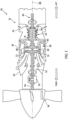
- FIG. 1 illustrates a propulsion system 20 configured for an aircraft.
- the aircraft may be a fixed-wing aircraft (e.g., an airplane), a rotary-wing aircraft (e.g., a helicopter), a tilt-rotor aircraft, a tilt-wing aircraft, or any other aerial vehicle.
- the aircraft may be a manned aerial vehicle or an unmanned aerial vehicle (UAV, e.g., a drone).
- the aircraft propulsion system 20 of FIG. 1 includes a gas turbine engine 22.
- gas turbine engine 22 e.g., the present disclosure is also applicable to propulsion systems which do not include gas turbine engines such as, but not limited to, a battery-electric propulsion system (e.g., an electric-motor driven propeller system).
- FIG. 1 illustrates a side, cutaway view of the gas turbine engine 22.
- the gas turbine engine 22 of FIG. 1 is configured as a turboprop gas turbine engine, however, the present disclosure is not limited to turboprop gas turbine engines. It should be understood that aspects of the present disclosure may be equally applicable to other types of gas turbine engines including, but not limited to, a turboshaft gas turbine engine, a turbofan gas turbine engine, a turbojet gas turbine engine, or an open rotor gas turbine engine.
- the gas turbine engine 22 of FIG. 1 includes an air inlet 24, a compressor 26, a combustor 28, a high-pressure turbine 30, a power turbine 32, an exhaust 34, and an engine static structure 36.
- the air inlet 24, the compressor 26, the combustor 28, the high-pressure turbine 30, the power turbine 32, and the exhaust 34 are arranged along an axial centerline 38 (e.g., a rotational axis) of the gas turbine engine 22.
- the engine static structure 36 may include, for example, one or more engine cases for the gas turbine engine 22.
- the engine static structure 36 may additionally include cowlings, bearing assemblies, and/or other structural components of the gas turbine engine 22.
- the one or more engine cases form, house, and/or structurally support one or more of the air inlet 24, the compressor 26, the combustor 28, the high-pressure turbine 30, the power turbine 32, and the exhaust 34.
- Components of the gas turbine engine 22 of FIG. 1 such as components of the compressor 26, the high-pressure turbine 30, and the power turbine 32, are arranged as a first rotational assembly 40 (e.g., a high-pressure spool) and a second rotational assembly 42 (e.g., a power spool).
- the first rotational assembly 40 and the second rotational assembly 42 are mounted for rotation about the axial centerline 38 relative to the engine static structure 36.
- the gas turbine engine 22 of FIG. 1 has a "free turbine" configuration. The present disclosure, however, is not limited to free turbine gas turbine engine configurations.
- the first rotational assembly 40 includes a first shaft 44, a bladed compressor rotor 46 for the compressor 26, and a bladed first turbine rotor 48 for the high-pressure turbine 30.
- the first shaft 44 interconnects the bladed compressor rotor 46 and the bladed first turbine rotor 48.
- the second rotational assembly 42 includes a second shaft 50, a bladed second turbine rotor 52 for the power turbine 32, a reduction gear box (RGB) 54, a drive shaft 56, and a rotational load 58.
- the second shaft 50 is connected to the bladed power turbine rotor 52.
- the drive shaft 56 is connected to the rotational load 58.
- the second shaft 50 and the drive shaft 56 are mechanically coupled with the RGB 54.
- the RGB 54 is configured to drive the drive shaft 56 at a reduced rotational speed relative to the second shaft 50. In other words, the RGB 54 is configured to facilitate a reduced speed ratio between the second shaft 50 and the drive shaft 56 in driving engagement with the rotational load 58.
- the rotational load 58 of FIG. 1 is configured as a propeller. The present disclosure, however, is not limited to propellers for the rotational load 58.
- ambient air enters the gas turbine engine 22 through the air inlet 24 and is directed into the compressor 26.
- the ambient air is compressed by the bladed compressor rotor 46 and directed into a combustion chamber 60 of the combustor 28.
- Fuel is injected into the combustion chamber 60 and mixed with the compressed air to provide a fuel-air mixture.
- This fuel-air mixture is ignited, and combustion products thereof flow through and sequentially cause the bladed first turbine rotor 48 and the bladed second turbine rotor 52 to rotate.
- the rotation of the bladed first turbine rotor 48 and the bladed second turbine rotor 52 respectively drive rotation of the first rotational assembly 40 and the second rotational assembly 42.
- Rotation of the second rotational assembly 42 further drives rotation of the rotational load 58 (e.g., the propeller) of FIG. 1 by the RGB 54, as previously discussed, to provide propulsion (e.g., thrust) for the propulsion system 20.
- Combustion exhaust gas flowing past the bladed second turbine rotor 52 is directed out of the gas turbine engine 22 through the exhaust 34.
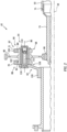
- FIG. 2 illustrates a side, cutaway view of a portion of the second rotational assembly 42 including the RGB 54.
- the RGB 54 of FIG. 2 includes a gear assembly 62 (e.g., a planetary gear assembly; sometimes referred to as an "epicyclic gear assembly”) and a planet carrier 64.
- the gear assembly 62 and the planet carrier 64 operably couple the second shaft 50 to the drive shaft 56.
- the gear assembly 62 includes a sun gear 66, a plurality of planet gears 68, a first ring gear 70, and a second ring gear 72.
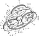
- FIG. 3 illustrates a perspective view of the gear assembly 62.
- FIG. 4 illustrates a side, cutaway view of a portion of the gear assembly 62.
- the sun gear 66 is mounted on, formed by, or otherwise connected to the second shaft 50 (e.g., by one or more intermediate components).
- the sun gear 66 of FIG. 2 is mounted on a drive shaft 73.
- the drive shaft 73 of FIG. 2 is mounted to the second shaft 50 by a splined connection 75 allowing axial movement between the drive shaft 73 and the second shaft 50.
- the sun gear 66 is configured to rotate with the second shaft 50 about the axial centerline 38.
- the sun gear 66 of FIG. 3 includes a double helical gear pattern 74 (sometimes referred to as a "herringbone" pattern).
- the double helical gear pattern 74 is formed by a first set of helical teeth 76 and a second set of helical teeth 78.
- Each of the first set of helical teeth 76 and the second set of helical teeth 78 includes a plurality of teeth arranged circumferentially about (e.g., completely around) the sun gear 66.
- the first set of helical teeth 76 are disposed adjacent (e.g., laterally adjacent) the second set of helical teeth 78.
- the plurality of teeth of the first set of helical teeth 76 are angled in opposite directions relative to the plurality of teeth of the second set of helical teeth 78.
- the sun gear 66 has a diameter D1 (e.g., extending perpendicular to the axial centerline 38).
- the sun gear 66 may include a spur gear pattern as an alternative to the double helical gear pattern 74.
- Each of the plurality of planet gears 68 includes a main gear 80, a first lateral gear 82, and a second lateral gear 84.
- the main gear 80, the first lateral gear 82, and the second lateral gear 84 may form a single, monolithic body of the respective planet gear 68.
- the gear assembly 62 of FIG. 3 includes three planet gears 68, however, the present disclosure is not limited to any particular number of planet gears for the planet gear assembly 62.
- the main gear 80 extends circumferentially about (e.g., completely around) a planet gear axis 86.
- the main gear 80 has a diameter D2 (e.g., extending perpendicular to the planet gear axis 86).
- the diameter D2 may be greater than the diameter D1 of the sun gear 66.
- the main gear 80 extends (e.g., along the planet gear axis 86) between and to a first lateral side 88 of the main gear 80 and a second lateral side 90 of the main gear 80.
- the main gear 80 includes a double helical gear pattern 92 matching the double helical gear pattern 74.
- the double helical gear pattern 92 meshes with (e.g., is operably engaged with) the double helical gear pattern 74. Similar to the double helical gear pattern 74, the double helical gear pattern 92 is formed by a first set of helical teeth 94 and a second set of helical teeth 96. Each of the first set of helical teeth 94 and the second set of helical teeth 96 includes a plurality of teeth arranged circumferentially about (e.g., completely around) the main gear 80. The first set of helical teeth 94 are disposed adjacent (e.g., laterally adjacent) the second set of helical teeth 96.
- the plurality of teeth of the first set of helical teeth 94 are angled in opposite directions relative to the plurality of teeth of the second set of helical teeth 96.
- the main gear 80 may also include a spur gear pattern as an alternative to the double helical gear pattern 92.
- the double helical gear pattern 74 and the double helical gear pattern 92 facilitate higher loading capacity of the gear assembly 62.
- the gear assembly 62 may exhibit a greater power output for a same geometrical envelope size in comparison to at least some conventional gear assemblies.
- the splined connection 75 between the drive shaft 73 and the second shaft 50 facilitates axial looseness of the gear assembly 62 relative to the second shaft 50 to accommodate axial movement (e.g., due to gear assembly 62 tolerance stack up, gear assembly 62 loading, and thermal deflection) of the gear assembly 62 which may be more significant, in comparison to at least some conventional gear assemblies, due to the double helical gear pattern 74, 92 mating arrangement between the sun gear 66 and the main gears 80.
- Each of the first lateral gear 82 and the second lateral gear 84 extends circumferentially about (e.g., completely around) a planet gear axis 86.
- Each of the first lateral gear 82 and the second lateral gear 84 has a diameter D3 (e.g., extending perpendicular to the planet gear axis 86). The diameter D3 may be less than the diameter D1 of the sun gear 66 and/or the diameter D2 of the main gear 80.
- the first lateral gear 82 is disposed at (e.g., on, adjacent, or proximate) the first lateral side 88.
- the second lateral gear 84 is disposed at (e.g., on, adjacent, or proximate) the second lateral side 90.
- the first lateral gear 82 and the second lateral gear 84 include a spur gear pattern 98.
- the spur gear pattern 98 includes a plurality of teeth 100 arranged circumferentially about (e.g., completely around) the first lateral gear 82 and the second lateral gear 84, respectively.
- the plurality of teeth 100 extend axially or substantially axially relative to the planet gear axis 86.
- the first lateral gear 82 and the second lateral gear 84 may include a helical gear pattern as an alternative to the spur gear pattern 98.
- the helical gear pattern of the first lateral gear 82 and the second lateral gear 84 may form a double helical gear configuration.
- the teeth of the helical gear pattern for the first lateral gear 82 may be angled in opposite directions relative to the teeth of the helical gear pattern for the second lateral gear 84.
- Each of the first ring gear 70 and the second ring gear 72 extend circumferentially about (e.g., completely around) the axial centerline 38.
- the first ring gear 70 is spaced (e.g., laterally spaced) from the second ring gear 72 along the axial centerline 38.
- Each of the first ring gear 70 and the second ring gear 72 extends between and to an inner radial side 102 of the respective ring gear 70, 72 and an outer radial side 104 of the respective ring gear 70, 72.
- Each of the first ring gear 70 and the second ring gear 72 include a spur gear pattern 106.
- the spur gear pattern 106 includes a plurality of teeth 108 arranged circumferentially about (e.g., completely around) the first ring gear 70 and the second ring gear 72, respectively, at (e.g., on, adjacent, or proximate) the inner radial side 102.
- the plurality of teeth 108 extend axially or substantially axially relative to the axial centerline 38.
- the spur gear pattern 106 of the first ring gear 70 meshes with (e.g., is operably engaged with) the spur gear pattern 98 of the first lateral gear 82 for each planet gear 68.
- the spur gear pattern 106 of the second ring gear 72 meshes with (e.g., is operably engaged with) the spur gear pattern 98 of the second lateral gear 84 for each planet gear 68.
- Each of the first ring gear 70 and the second ring gear 72 may be rotationally fixed relative to the axial centerline 38.
- the first ring gear 70 and the second ring gear 72 may be fixedly mounted to the engine static structure 36 (see FIG. 1 ) or another fixed structure of the propulsion system 20 (see FIG. 1 ).
- the first lateral gear 82 and the second lateral gear 84 include a helical gear pattern
- the first ring gear 70 and the second ring gear 72 may also include a matching gear pattern as an alternative to the spur gear pattern 106.
- FIGS. 2 and 4 illustrate portions of the planet carrier 64.
- the planet carrier 64 includes a carrier plate 110 and a plurality of planet shafts 112.
- the planet carrier 64 may further include a plurality of bearings 114.
- the carrier plate 110 extends circumferentially about (e.g., completely around) the axial centerline 38.
- the carrier plate 110 extends between and to a first lateral side 116 of the carrier plate 110 and a second lateral side 118 of the carrier plate 110.
- the first lateral side 116 is coupled to the drive shaft 56.
- the carrier plate 110 of FIG. 4 includes a connector 120 at (e.g., on, adjacent, or proximate) the first lateral side 116.
- the connector 120 is mounted to the drive shaft 56 (e.g., by a splined connection) and configured to drive rotation of the drive shaft 56 based on rotation of the planet carrier 64. Alternatively, however, the drive shaft 56 may be directly coupled to the carrier plate 110.
- the plurality of planet shafts 112 extend outward from the second lateral side 118.
- Each planet shaft 112 is rotatably coupled to a respective one of the planet gears 68.
- the planet carrier 64 may include three planet shafts 112 corresponding to the three respective planet gears 68 of the gear assembly 62 of FIGS. 2-4 .
- Each planet shaft 112 extends (e.g., axially extends) through the respective planet gear 68 along the planet gear axis 86 for the respective planet gear 68.
- each planet gear 68 is mounted on a respective one of the planet shafts 112 for rotation about the respective planet gear axis 86.
- the planet carrier 64 may further include the plurality of bearings 114, with each bearing 114 disposed between each planet shaft 112 and each respective planet gear 68.
- Each bearing 114 is extends circumferentially about (e.g., completely around) a respective one of the planet shafts 112 to rotatably support the respective one of the planet gears 68.
- Each bearing 114 may be fixedly mounted onto a respective one of the planet shafts 112.
- the plurality of bearings 114 may be configured, for example, as journal bearings (e.g., plain bearings), oil film bearings, or the like.
- Each bearing 114 extends (e.g., axially extends along the respective planet gear axis 86) between and to a first lateral end 122 of the bearing 114 and a second lateral end 124 of the bearing 114.
- Each bearing 114 may include a first shoulder portion 126 and a second shoulder portion 128.
- the first shoulder portion 126 may be disposed at (e.g., on, adjacent, or proximate) the first lateral side 122.
- the second shoulder portion 128 may be disposed at (e.g., on, adjacent, or proximate) the second lateral end 124.
- the first shoulder portion 126 and the second shoulder portion 128 may extend radially outward (e.g., relative to the planet gear axis 86) from surrounding portions of the bearing 114.
- the first shoulder portion 126 and the second shoulder portion 128 may prevent or limit relative axial movement (e.g., relative to the planet gear axis 86) of the planet gears 68 which may otherwise result due to the spur gear patterns 98, 106 of the lateral gears 82, 84 and the ring gears 70, 72.
- the bearing 114 may form an axial gap 130 between the first lateral gear 82 and the first shoulder portion 126 and/or between the second lateral gear 84 and the second shoulder portion 128 to accommodate some axial movement of the planet gears 68.
- the present disclosure is not limited to the formation of the axial gap 130 between the bearing 114 and the respective planet gear 68.
- the second shaft 50 drives rotation of the sun gear 66 about the axial centerline 38.
- the sun gear 66 effects rotation of the plurality of planet gears 68 (e.g., by engagement with the main gear 80) about the respective planet gear axis 86 of each planet gear 68.
- Rotation of the planet gears 68 causes the planet gears 68 to circumferentially travel along the first ring gear 70 and the second ring gear 72 (e.g., by engagement with first lateral gear 82 and the second lateral gear 84), thereby effecting rotation of the planet carrier 64 and driving the drive shaft 56 and the rotational load 58.
- the RGB 54 drives the drive shaft 56 at a reduced rotational speed relative to the second shaft 50 (e.g., a reduced speed ratio).
- first ring gear 70 and the second ring gear 72 may be rotationally fixed (e.g., relative to the axial centerline 38) and the rotation of the planet gears 68 about the first ring gear 70 and the second ring gear 72 may drive rotation of the planet carrier 64, the drive shaft 56, and the rotational load 58.
- first ring gear 70 and the second ring gear 72 may be configured for rotation about the axial centerline 38.
- first ring gear 70 and the second ring gear 72 may be mounted to the drive shaft 56 and configured to drive rotation of the drive shaft 56 and the rotational load 58.
- the planet carrier 64 may be rotationally fixed (e.g., relative to the axial centerline 38). Accordingly, the planet carrier 64 may rotationally fix the planet gears 68 relative to the axial centerline 38. Rotation of the planet gears 68 may, therefore, cause the first ring gear 70 and the second ring gear 72 to rotate about the axial centerline 38, thereby driving the drive shaft 56 and the rotational load 58.
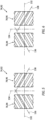
- FIGS. 5 and 6 portions of exemplary configurations of the double helical gear pattern 74 and the double helical gear pattern 92 are illustrated.
- the double helical gear patterns 74, 92 of FIGS. 5 and 6 are illustrated relative to an axial reference line 132 (e.g., parallel to the axial centerline 38; see FIGS. 1 and 2 ) and a circumferential reference line 134 (e.g., extending circumferentially about the axial centerline 38).
- the circumferential reference line 134 of FIGS. 5 and 6 is disposed axially equidistant between the first set of helical teeth 76, 94 and the second set of helical teeth 78, 96.
- a direction of the orientation (e.g., helical orientation) of the first set of helical teeth 76, 94 is identified by a first helical axis 136 extending through a middle position of the first set of helical teeth 76, 94.
- the first set of helical teeth 76, 94 extend in a direction along the first helical axis 136.
- a direction of the orientation (e.g., helical orientation) of the second set of helical teeth 78, 96 is identified by a second helical axis 138 extending through a middle position of the second set of helical teeth 78, 96.
- the second set of helical teeth 78, 96 extend (e.g., axially extend) in a direction along the second helical axis 138.
- the first set of helical teeth 76, 94 and the second set of helical teeth 78, 96 may be synchronous (e.g., circumferentially aligned), as shown in FIG. 5 .
- the first helical axis 136 and the second helical axis 138 of FIG. 5 intersect at the circumferential reference line 134.
- the first set of helical teeth 76, 94 and the second set of helical teeth 78, 96 may be asynchronous (e.g., circumferentially staggered), as shown in FIG. 6 .
- the first helical axis 136 and the second helical axis 138 of FIG. 6 intersect the circumferential reference line 134 at circumferentially offset positions.
- the asynchronous configuration of the first set of helical teeth 76, 94 and the second set of helical teeth 78, 96 may facilitate reduced torque fluctuation of the gear assembly 62 (see FIGS. 2-4 ), for example, in comparison to a synchronous configuration of the first set of helical teeth 76, 94 and the second set of helical teeth 78, 96.
- any one of these structures may describe the operations as a sequential process, many of the operations can be performed in parallel or concurrently.
- the order of the operations may be rearranged.
- a process may correspond to a method, a function, a procedure, a subroutine, a subprogram, etc.
Landscapes
- Engineering & Computer Science (AREA)
- General Engineering & Computer Science (AREA)
- Mechanical Engineering (AREA)
- Chemical & Material Sciences (AREA)
- Combustion & Propulsion (AREA)
- Retarders (AREA)
- Gear Transmission (AREA)
Abstract
Description
- This disclosure relates generally to aircraft propulsion systems and, more particularly, to speed-changing gearbox assemblies for aircraft propulsion systems.
- Aircraft propulsion systems may include a speed-changing gearbox to drive one or more rotational loads. For example, an aircraft propulsion system may include a reduction gearbox (RGB) to drive a propeller at a reduced rotational speed relative to a turbine of a gas turbine engine. Various RGB assemblies are known in the art. While these known assemblies have various advantages, there is still room in the art for improvement.
- It should be understood that any or all of the features or embodiments described herein can be used or combined in any combination with each and every other feature or embodiment described herein unless expressly noted otherwise.
- According to an aspect of the present invention, an assembly for an aircraft propulsion system includes an output shaft and a gear assembly. The gear assembly is configured to drive rotation of the output shaft. The gear assembly includes a sun gear, a plurality of planet gears, a first ring gear, and a second ring gear. The sun gear is rotatable about a rotational axis. The sun gear includes a first double helical gear pattern. Each planet gear of the plurality of planet gears includes a main gear, a first lateral gear, and a second lateral gear. The main gear includes a second double helical gear pattern engaged with the first double helical gear pattern. The first lateral gear is engaged with the first ring gear. The second lateral gear is engaged with the second ring gear. The first ring gear is axially spaced from the second ring gear relative to the rotational axis.
- In an embodiment of the above, the first ring gear and the second ring gear may be rotationally fixed relative to the rotational axis.
- In another embodiment according to any of the previous embodiments, each of the first ring gear and the second ring gear may include a first spur gear pattern and each of the first lateral gear and the second lateral gear may include a second spur gear pattern.
- In another embodiment according to any of the previous embodiments, each of the first ring gear and the second ring gear may extend between and to an inner radial side and an outer radial side. The first spur gear pattern may be disposed at the inner radial side.
- In another embodiment according to any of the previous embodiments, the main gear may have a first diameter and each of the first lateral gear and the second lateral gear may have a second diameter. The first diameter may be greater than the second diameter.
- In another embodiment according to any of the previous embodiments, the assembly may further include a planet carrier. The planet carrier may include a carrier plate and a plurality of shafts. Each shaft of the plurality of shafts may be connected to a respective planet gear of the plurality of planet gears. The planet carrier plate may be connected to the output shaft.
- In another embodiment according to any of the previous embodiments, the planet carrier may include a plurality of journal bearings, with each journal bearing positioned between a respective shaft of the plurality of shafts and a respective planet gear of the plurality of planet gears.
- In another embodiment according to any of the previous embodiments, each journal bearing of the plurality of journal bearings may extend between and to a first axial end and a second axial end. Each journal bearing of the plurality of journal bearings may include a first shoulder disposed at the first axial end and a second shoulder disposed at the second axial end. Each of the first shoulder and the second shoulder may be positioned axially adjacent a respective planet gear of the plurality of planet gears.
- In another embodiment according to any of the previous embodiments, the main gear, the first lateral gear, and the second lateral gear may form a monolithic body of each respective planet gear of the plurality of planet gears.
- In another embodiment according to any of the previous embodiments, the first double helical gear pattern may include a first set of helical teeth and a second set of helical teeth. The first set of helical teeth may be circumferentially staggered relative to the second set of helical teeth.
- In another embodiment according to any of the previous embodiments, the first double helical gear pattern may include a first set of helical teeth and a second set of helical teeth. The first set of helical teeth may be circumferentially aligned relative to the second set of helical teeth.
- In another embodiment according to any of the previous embodiments, the main gear may have a first diameter and the sun gear may have a second diameter. The first diameter may be greater than the second diameter.
- According to another aspect of the present invention, an aircraft propulsion system includes a propeller, a gas turbine engine, and a reduction gear box. The propeller is configured for rotation about a rotational axis. The gas turbine engine includes a bladed turbine rotor and a shaft connected to the bladed turbine rotor. The reduction gear box includes a gear assembly connected to the shaft and the propeller. The gear assembly is configured to drive the propeller at a reduced rotational speed relative to the shaft. The gear assembly includes a sun gear, a plurality of planet gears, and a first ring gear, and a second ring gear. The sun gear is rotatable about a rotational axis. The sun gear includes a first double helical gear pattern. Each planet gear of the plurality of planet gears includes a main gear, a first lateral gear, and a second lateral gear. The main gear includes a second double helical gear pattern engaged with the first double helical gear pattern. The first lateral gear is engaged with the first ring gear. The second lateral gear is engaged with the second ring gear.
- In an embodiment of the above, the first ring gear and the second ring gear may be rotationally fixed relative to the rotational axis.
- In another embodiment according to any of the previous embodiments, each of the first ring gear and the second ring gear may include a first spur gear pattern and each of the first lateral gear and the second lateral gear may include a second spur gear pattern.
- According to another aspect of the present invention, an assembly for an aircraft propulsion system includes an output shaft and a gear assembly. The gear assembly is configured to drive rotation of the output shaft. The gear assembly includes a sun gear, a plurality of planet gears, a first ring gear, and a second ring gear. The sun gear is rotatable about a rotational axis. The sun gear includes a first double helical gear pattern. Each planet gear of the plurality of planet gears includes a main gear, a first lateral gear, and a second lateral gear. The main gear includes a second double helical gear pattern engaged with the first double helical gear pattern. The first lateral gear is engaged with the first ring gear. The second lateral gear is engaged with the second ring gear. Each of the first ring gear and the second ring gear includes a first spur gear pattern and each of the first lateral gear and the second lateral gear includes a second spur gear pattern.
- In an embodiment of the above, each of the first ring gear and the second ring gear may extend between and to an inner radial side and an outer radial side. The first spur gear pattern may be disposed at the inner radial side.
- In another embodiment according to any of the previous embodiments, the main gear may have a first diameter. Each of the first lateral gear and the second lateral gear may have a second diameter. The first diameter may be greater than the second diameter.
- In another embodiment according to any of the previous embodiments, the first double helical gear pattern may include a first set of helical teeth and a second set of helical teeth. The first set of helical teeth may be circumferentially staggered relative to the second set of helical teeth.
- In another embodiment according to any of the previous embodiments, the assembly may further include a planet carrier. The planet carrier may include a carrier plate and a plurality of shafts. Each shaft of the plurality of shafts may be connected to a respective planet gear of the plurality of planet gears. The carrier plate may be rotationally fixed relative to the rotational axis.
- The present disclosure, and all its aspects, embodiments and advantages associated therewith will become more readily apparent in view of the detailed description provided below, including the accompanying drawings.
-
-
FIG. 1 schematically illustrates a side, cutaway view of an aircraft propulsion system, in accordance with one or more embodiments of the present disclosure. -
FIG. 2 illustrates a side, cutaway view of a portion of a rotational assembly for the aircraft propulsion system ofFIG. 1 , in accordance with one or more embodiments of the present disclosure. -
FIG. 3 illustrates a perspective view of a gear assembly for the rotational assembly ofFIG. 2 , in accordance with one or more embodiments of the present disclosure. -
FIG. 4 illustrates a cutaway view of a portion of the gear assembly for the rotational assembly ofFIG. 2 , in accordance with one or more embodiments of the present disclosure. -
FIG. 5 illustrates a view of a circumferential portion of a double helical gear pattern for the gear assembly ofFIG. 3 , in accordance with one or more embodiments of the present disclosure. -
FIG. 6 illustrates a view of a circumferential portion of another double helical gear pattern for the gear assembly ofFIG. 3 , in accordance with one or more embodiments of the present disclosure. -
FIG. 1 illustrates apropulsion system 20 configured for an aircraft. Briefly, the aircraft may be a fixed-wing aircraft (e.g., an airplane), a rotary-wing aircraft (e.g., a helicopter), a tilt-rotor aircraft, a tilt-wing aircraft, or any other aerial vehicle. Moreover, the aircraft may be a manned aerial vehicle or an unmanned aerial vehicle (UAV, e.g., a drone). Theaircraft propulsion system 20 ofFIG. 1 includes agas turbine engine 22. However, the present disclosure is also applicable to propulsion systems which do not include gas turbine engines such as, but not limited to, a battery-electric propulsion system (e.g., an electric-motor driven propeller system). -
FIG. 1 illustrates a side, cutaway view of thegas turbine engine 22. Thegas turbine engine 22 ofFIG. 1 is configured as a turboprop gas turbine engine, however, the present disclosure is not limited to turboprop gas turbine engines. It should be understood that aspects of the present disclosure may be equally applicable to other types of gas turbine engines including, but not limited to, a turboshaft gas turbine engine, a turbofan gas turbine engine, a turbojet gas turbine engine, or an open rotor gas turbine engine. - The
gas turbine engine 22 ofFIG. 1 includes anair inlet 24, acompressor 26, acombustor 28, a high-pressure turbine 30, apower turbine 32, anexhaust 34, and an enginestatic structure 36. Theair inlet 24, thecompressor 26, thecombustor 28, the high-pressure turbine 30, thepower turbine 32, and theexhaust 34 are arranged along an axial centerline 38 (e.g., a rotational axis) of thegas turbine engine 22. The enginestatic structure 36 may include, for example, one or more engine cases for thegas turbine engine 22. The enginestatic structure 36 may additionally include cowlings, bearing assemblies, and/or other structural components of thegas turbine engine 22. The one or more engine cases form, house, and/or structurally support one or more of theair inlet 24, thecompressor 26, thecombustor 28, the high-pressure turbine 30, thepower turbine 32, and theexhaust 34. - Components of the
gas turbine engine 22 ofFIG. 1 , such as components of thecompressor 26, the high-pressure turbine 30, and thepower turbine 32, are arranged as a first rotational assembly 40 (e.g., a high-pressure spool) and a second rotational assembly 42 (e.g., a power spool). The firstrotational assembly 40 and the secondrotational assembly 42 are mounted for rotation about theaxial centerline 38 relative to the enginestatic structure 36. Thegas turbine engine 22 ofFIG. 1 has a "free turbine" configuration. The present disclosure, however, is not limited to free turbine gas turbine engine configurations. - The first
rotational assembly 40 includes afirst shaft 44, abladed compressor rotor 46 for thecompressor 26, and a bladedfirst turbine rotor 48 for the high-pressure turbine 30. Thefirst shaft 44 interconnects the bladedcompressor rotor 46 and the bladedfirst turbine rotor 48. - The second
rotational assembly 42 includes asecond shaft 50, a bladedsecond turbine rotor 52 for thepower turbine 32, a reduction gear box (RGB) 54, adrive shaft 56, and arotational load 58. Thesecond shaft 50 is connected to the bladedpower turbine rotor 52. Thedrive shaft 56 is connected to therotational load 58. Thesecond shaft 50 and thedrive shaft 56 are mechanically coupled with theRGB 54. TheRGB 54 is configured to drive thedrive shaft 56 at a reduced rotational speed relative to thesecond shaft 50. In other words, theRGB 54 is configured to facilitate a reduced speed ratio between thesecond shaft 50 and thedrive shaft 56 in driving engagement with therotational load 58. Therotational load 58 ofFIG. 1 is configured as a propeller. The present disclosure, however, is not limited to propellers for therotational load 58. - During operation of the
gas turbine engine 22 ofFIG. 1 , ambient air enters thegas turbine engine 22 through theair inlet 24 and is directed into thecompressor 26. The ambient air is compressed by the bladedcompressor rotor 46 and directed into acombustion chamber 60 of thecombustor 28. Fuel is injected into thecombustion chamber 60 and mixed with the compressed air to provide a fuel-air mixture. This fuel-air mixture is ignited, and combustion products thereof flow through and sequentially cause the bladedfirst turbine rotor 48 and the bladedsecond turbine rotor 52 to rotate. The rotation of the bladedfirst turbine rotor 48 and the bladedsecond turbine rotor 52 respectively drive rotation of the firstrotational assembly 40 and the secondrotational assembly 42. Rotation of the secondrotational assembly 42 further drives rotation of the rotational load 58 (e.g., the propeller) ofFIG. 1 by theRGB 54, as previously discussed, to provide propulsion (e.g., thrust) for thepropulsion system 20. Combustion exhaust gas flowing past the bladedsecond turbine rotor 52 is directed out of thegas turbine engine 22 through theexhaust 34. -
FIG. 2 illustrates a side, cutaway view of a portion of the secondrotational assembly 42 including theRGB 54. TheRGB 54 ofFIG. 2 includes a gear assembly 62 (e.g., a planetary gear assembly; sometimes referred to as an "epicyclic gear assembly") and aplanet carrier 64. Thegear assembly 62 and theplanet carrier 64 operably couple thesecond shaft 50 to thedrive shaft 56. - Referring to
FIGS. 2-4 , thegear assembly 62 includes asun gear 66, a plurality of planet gears 68, afirst ring gear 70, and asecond ring gear 72.FIG. 3 illustrates a perspective view of thegear assembly 62.FIG. 4 illustrates a side, cutaway view of a portion of thegear assembly 62. - The
sun gear 66 is mounted on, formed by, or otherwise connected to the second shaft 50 (e.g., by one or more intermediate components). For example, thesun gear 66 ofFIG. 2 is mounted on adrive shaft 73. Thedrive shaft 73 ofFIG. 2 is mounted to thesecond shaft 50 by asplined connection 75 allowing axial movement between thedrive shaft 73 and thesecond shaft 50. Thesun gear 66 is configured to rotate with thesecond shaft 50 about theaxial centerline 38. Thesun gear 66 ofFIG. 3 includes a double helical gear pattern 74 (sometimes referred to as a "herringbone" pattern). The double helical gear pattern 74 is formed by a first set ofhelical teeth 76 and a second set ofhelical teeth 78. Each of the first set ofhelical teeth 76 and the second set ofhelical teeth 78 includes a plurality of teeth arranged circumferentially about (e.g., completely around) thesun gear 66. The first set ofhelical teeth 76 are disposed adjacent (e.g., laterally adjacent) the second set ofhelical teeth 78. The plurality of teeth of the first set ofhelical teeth 76 are angled in opposite directions relative to the plurality of teeth of the second set ofhelical teeth 78. Thesun gear 66 has a diameter D1 (e.g., extending perpendicular to the axial centerline 38). In some embodiments, thesun gear 66 may include a spur gear pattern as an alternative to the double helical gear pattern 74. - Each of the plurality of planet gears 68 includes a
main gear 80, afirst lateral gear 82, and asecond lateral gear 84. Themain gear 80, thefirst lateral gear 82, and thesecond lateral gear 84 may form a single, monolithic body of therespective planet gear 68. Thegear assembly 62 ofFIG. 3 includes threeplanet gears 68, however, the present disclosure is not limited to any particular number of planet gears for theplanet gear assembly 62. - The
main gear 80 extends circumferentially about (e.g., completely around) aplanet gear axis 86. Themain gear 80 has a diameter D2 (e.g., extending perpendicular to the planet gear axis 86). The diameter D2 may be greater than the diameter D1 of thesun gear 66. Themain gear 80 extends (e.g., along the planet gear axis 86) between and to a firstlateral side 88 of themain gear 80 and a secondlateral side 90 of themain gear 80. Themain gear 80 includes a doublehelical gear pattern 92 matching the double helical gear pattern 74. The doublehelical gear pattern 92 meshes with (e.g., is operably engaged with) the double helical gear pattern 74. Similar to the double helical gear pattern 74, the doublehelical gear pattern 92 is formed by a first set ofhelical teeth 94 and a second set ofhelical teeth 96. Each of the first set ofhelical teeth 94 and the second set ofhelical teeth 96 includes a plurality of teeth arranged circumferentially about (e.g., completely around) themain gear 80. The first set ofhelical teeth 94 are disposed adjacent (e.g., laterally adjacent) the second set ofhelical teeth 96. The plurality of teeth of the first set ofhelical teeth 94 are angled in opposite directions relative to the plurality of teeth of the second set ofhelical teeth 96. In embodiments in which the sun gear includes a spur gear pattern, themain gear 80 may also include a spur gear pattern as an alternative to the doublehelical gear pattern 92. - The double helical gear pattern 74 and the double
helical gear pattern 92 facilitate higher loading capacity of thegear assembly 62. For example, thegear assembly 62 may exhibit a greater power output for a same geometrical envelope size in comparison to at least some conventional gear assemblies. Thesplined connection 75 between thedrive shaft 73 and thesecond shaft 50 facilitates axial looseness of thegear assembly 62 relative to thesecond shaft 50 to accommodate axial movement (e.g., due togear assembly 62 tolerance stack up,gear assembly 62 loading, and thermal deflection) of thegear assembly 62 which may be more significant, in comparison to at least some conventional gear assemblies, due to the doublehelical gear pattern 74, 92 mating arrangement between thesun gear 66 and the main gears 80. - Each of the
first lateral gear 82 and thesecond lateral gear 84 extends circumferentially about (e.g., completely around) aplanet gear axis 86. Each of thefirst lateral gear 82 and thesecond lateral gear 84 has a diameter D3 (e.g., extending perpendicular to the planet gear axis 86). The diameter D3 may be less than the diameter D1 of thesun gear 66 and/or the diameter D2 of themain gear 80. Thefirst lateral gear 82 is disposed at (e.g., on, adjacent, or proximate) the firstlateral side 88. Thesecond lateral gear 84 is disposed at (e.g., on, adjacent, or proximate) the secondlateral side 90. Each of thefirst lateral gear 82 and thesecond lateral gear 84 include aspur gear pattern 98. Thespur gear pattern 98 includes a plurality ofteeth 100 arranged circumferentially about (e.g., completely around) thefirst lateral gear 82 and thesecond lateral gear 84, respectively. The plurality ofteeth 100 extend axially or substantially axially relative to theplanet gear axis 86. In some embodiments, thefirst lateral gear 82 and thesecond lateral gear 84 may include a helical gear pattern as an alternative to thespur gear pattern 98. The helical gear pattern of thefirst lateral gear 82 and thesecond lateral gear 84 may form a double helical gear configuration. For example, the teeth of the helical gear pattern for thefirst lateral gear 82 may be angled in opposite directions relative to the teeth of the helical gear pattern for thesecond lateral gear 84. - Each of the
first ring gear 70 and thesecond ring gear 72 extend circumferentially about (e.g., completely around) theaxial centerline 38. Thefirst ring gear 70 is spaced (e.g., laterally spaced) from thesecond ring gear 72 along theaxial centerline 38. Each of thefirst ring gear 70 and thesecond ring gear 72 extends between and to an innerradial side 102 of therespective ring gear radial side 104 of therespective ring gear first ring gear 70 and thesecond ring gear 72 include aspur gear pattern 106. Thespur gear pattern 106 includes a plurality ofteeth 108 arranged circumferentially about (e.g., completely around) thefirst ring gear 70 and thesecond ring gear 72, respectively, at (e.g., on, adjacent, or proximate) the innerradial side 102. The plurality ofteeth 108 extend axially or substantially axially relative to theaxial centerline 38. Thespur gear pattern 106 of thefirst ring gear 70 meshes with (e.g., is operably engaged with) thespur gear pattern 98 of thefirst lateral gear 82 for eachplanet gear 68. Thespur gear pattern 106 of thesecond ring gear 72 meshes with (e.g., is operably engaged with) thespur gear pattern 98 of thesecond lateral gear 84 for eachplanet gear 68. Each of thefirst ring gear 70 and thesecond ring gear 72 may be rotationally fixed relative to theaxial centerline 38. For example, thefirst ring gear 70 and thesecond ring gear 72 may be fixedly mounted to the engine static structure 36 (seeFIG. 1 ) or another fixed structure of the propulsion system 20 (seeFIG. 1 ). In embodiments in which thefirst lateral gear 82 and thesecond lateral gear 84 include a helical gear pattern, thefirst ring gear 70 and thesecond ring gear 72 may also include a matching gear pattern as an alternative to thespur gear pattern 106. -
FIGS. 2 and4 illustrate portions of theplanet carrier 64. Theplanet carrier 64 includes acarrier plate 110 and a plurality ofplanet shafts 112. Theplanet carrier 64 may further include a plurality ofbearings 114. - The
carrier plate 110 extends circumferentially about (e.g., completely around) theaxial centerline 38. Thecarrier plate 110 extends between and to a firstlateral side 116 of thecarrier plate 110 and a secondlateral side 118 of thecarrier plate 110. The firstlateral side 116 is coupled to thedrive shaft 56. Thecarrier plate 110 ofFIG. 4 includes aconnector 120 at (e.g., on, adjacent, or proximate) the firstlateral side 116. Theconnector 120 is mounted to the drive shaft 56 (e.g., by a splined connection) and configured to drive rotation of thedrive shaft 56 based on rotation of theplanet carrier 64. Alternatively, however, thedrive shaft 56 may be directly coupled to thecarrier plate 110. - The plurality of
planet shafts 112 extend outward from the secondlateral side 118. Eachplanet shaft 112 is rotatably coupled to a respective one of the planet gears 68. For example, theplanet carrier 64 may include threeplanet shafts 112 corresponding to the three respective planet gears 68 of thegear assembly 62 ofFIGS. 2-4 . Eachplanet shaft 112 extends (e.g., axially extends) through therespective planet gear 68 along theplanet gear axis 86 for therespective planet gear 68. Thus, eachplanet gear 68 is mounted on a respective one of theplanet shafts 112 for rotation about the respectiveplanet gear axis 86. - The
planet carrier 64 may further include the plurality ofbearings 114, with each bearing 114 disposed between eachplanet shaft 112 and eachrespective planet gear 68. Each bearing 114 is extends circumferentially about (e.g., completely around) a respective one of theplanet shafts 112 to rotatably support the respective one of the planet gears 68. Each bearing 114 may be fixedly mounted onto a respective one of theplanet shafts 112. The plurality ofbearings 114 may be configured, for example, as journal bearings (e.g., plain bearings), oil film bearings, or the like. - Each bearing 114 extends (e.g., axially extends along the respective planet gear axis 86) between and to a first
lateral end 122 of thebearing 114 and a secondlateral end 124 of thebearing 114. Each bearing 114 may include afirst shoulder portion 126 and asecond shoulder portion 128. Thefirst shoulder portion 126 may be disposed at (e.g., on, adjacent, or proximate) the firstlateral side 122. Thesecond shoulder portion 128 may be disposed at (e.g., on, adjacent, or proximate) the secondlateral end 124. Thefirst shoulder portion 126 and thesecond shoulder portion 128 may extend radially outward (e.g., relative to the planet gear axis 86) from surrounding portions of thebearing 114. Thefirst shoulder portion 126 and thesecond shoulder portion 128 may prevent or limit relative axial movement (e.g., relative to the planet gear axis 86) of the planet gears 68 which may otherwise result due to thespur gear patterns bearing 114 may form anaxial gap 130 between thefirst lateral gear 82 and thefirst shoulder portion 126 and/or between thesecond lateral gear 84 and thesecond shoulder portion 128 to accommodate some axial movement of the planet gears 68. However, the present disclosure is not limited to the formation of theaxial gap 130 between the bearing 114 and therespective planet gear 68. - During operation of the
RGB 54, thesecond shaft 50 drives rotation of thesun gear 66 about theaxial centerline 38. Thesun gear 66 effects rotation of the plurality of planet gears 68 (e.g., by engagement with the main gear 80) about the respectiveplanet gear axis 86 of eachplanet gear 68. Rotation of the planet gears 68 causes the planet gears 68 to circumferentially travel along thefirst ring gear 70 and the second ring gear 72 (e.g., by engagement withfirst lateral gear 82 and the second lateral gear 84), thereby effecting rotation of theplanet carrier 64 and driving thedrive shaft 56 and therotational load 58. Accordingly, theRGB 54 drives thedrive shaft 56 at a reduced rotational speed relative to the second shaft 50 (e.g., a reduced speed ratio). - As previously discussed, the
first ring gear 70 and thesecond ring gear 72 may be rotationally fixed (e.g., relative to the axial centerline 38) and the rotation of the planet gears 68 about thefirst ring gear 70 and thesecond ring gear 72 may drive rotation of theplanet carrier 64, thedrive shaft 56, and therotational load 58. In alternative embodiments (e.g., a star gear assembly), thefirst ring gear 70 and thesecond ring gear 72 may be configured for rotation about theaxial centerline 38. For example, thefirst ring gear 70 and thesecond ring gear 72 may be mounted to thedrive shaft 56 and configured to drive rotation of thedrive shaft 56 and therotational load 58. In this alternative embodiment, theplanet carrier 64 may be rotationally fixed (e.g., relative to the axial centerline 38). Accordingly, theplanet carrier 64 may rotationally fix the planet gears 68 relative to theaxial centerline 38. Rotation of the planet gears 68 may, therefore, cause thefirst ring gear 70 and thesecond ring gear 72 to rotate about theaxial centerline 38, thereby driving thedrive shaft 56 and therotational load 58. - Referring to
FIGS. 5 and 6 , portions of exemplary configurations of the double helical gear pattern 74 and the doublehelical gear pattern 92 are illustrated. The doublehelical gear patterns 74, 92 ofFIGS. 5 and 6 are illustrated relative to an axial reference line 132 (e.g., parallel to theaxial centerline 38; seeFIGS. 1 and2 ) and a circumferential reference line 134 (e.g., extending circumferentially about the axial centerline 38). Thecircumferential reference line 134 ofFIGS. 5 and 6 is disposed axially equidistant between the first set ofhelical teeth helical teeth helical teeth helical axis 136 extending through a middle position of the first set ofhelical teeth helical teeth helical axis 136. A direction of the orientation (e.g., helical orientation) of the second set ofhelical teeth helical axis 138 extending through a middle position of the second set ofhelical teeth helical teeth helical axis 138. In some embodiments, the first set ofhelical teeth helical teeth FIG. 5 . For example, the firsthelical axis 136 and the secondhelical axis 138 ofFIG. 5 intersect at thecircumferential reference line 134. In some other embodiments, the first set ofhelical teeth helical teeth FIG. 6 . For example, the firsthelical axis 136 and the secondhelical axis 138 ofFIG. 6 intersect thecircumferential reference line 134 at circumferentially offset positions. The asynchronous configuration of the first set ofhelical teeth helical teeth FIGS. 2-4 ), for example, in comparison to a synchronous configuration of the first set ofhelical teeth helical teeth - While the principles of the disclosure have been described above in connection with specific apparatuses and methods, it is to be clearly understood that this description is made only by way of example and not as limitation on the scope of the disclosure. Specific details are given in the above description to provide a thorough understanding of the embodiments. However, it is understood that the embodiments may be practiced without these specific details.
- It is noted that the embodiments may be described as a process which is depicted as a flowchart, a flow diagram, a block diagram, etc. Although any one of these structures may describe the operations as a sequential process, many of the operations can be performed in parallel or concurrently. In addition, the order of the operations may be rearranged. A process may correspond to a method, a function, a procedure, a subroutine, a subprogram, etc.
- The singular forms "a," "an," and "the" refer to one or more than one, unless the context clearly dictates otherwise. For example, the term "comprising a specimen" includes single or plural specimens and is considered equivalent to the phrase "comprising at least one specimen." The term "or" refers to a single element of stated alternative elements or a combination of two or more elements unless the context clearly indicates otherwise. As used herein, "comprises" means "includes." Thus, "comprising A or B," means "including A or B, or A and B," without excluding additional elements.
- It is noted that various connections are set forth between elements in the present description and drawings (the contents of which are included in this disclosure by way of reference). It is noted that these connections are general and, unless specified otherwise, may be direct or indirect and that this specification is not intended to be limiting in this respect. Any reference to attached, fixed, connected, or the like may include permanent, removable, temporary, partial, full and/or any other possible attachment option.
- No element, component, or method step in the present disclosure is intended to be dedicated to the public regardless of whether the element, component, or method step is explicitly recited in the claims. No claim element herein is to be construed under the provisions of 35 U.S.C. 112(f) unless the element is expressly recited using the phrase "means for." As used herein, the terms "comprise", "comprising", or any other variation thereof, are intended to cover a non-exclusive inclusion, such that a process, method, article, or apparatus that comprises a list of elements does not include only those elements but may include other elements not expressly listed or inherent to such process, method, article, or apparatus.
- While various inventive aspects, concepts and features of the disclosures may be described and illustrated herein as embodied in combination in the exemplary embodiments, these various aspects, concepts, and features may be used in many alternative embodiments, either individually or in various combinations and sub-combinations thereof. Unless expressly excluded herein all such combinations and sub-combinations are intended to be within the scope of the present application. Still further, while various alternative embodiments as to the various aspects, concepts, and features of the disclosures--such as alternative materials, structures, configurations, methods, devices, and components, and so on--may be described herein, such descriptions are not intended to be a complete or exhaustive list of available alternative embodiments, whether presently known or later developed. Those skilled in the art may readily adopt one or more of the inventive aspects, concepts, or features into additional embodiments and uses within the scope of the present application even if such embodiments are not expressly disclosed herein. For example, in the exemplary embodiments described above within the Detailed Description portion of the present specification, elements may be described as individual units and shown as independent of one another to facilitate the description. In alternative embodiments, such elements may be configured as combined elements.
Claims (15)
- An assembly for an aircraft propulsion system, the assembly comprising:an output shaft (56); anda gear assembly (62) configured to drive rotation of the output shaft (56), the gear assembly (62) including a sun gear (66), a plurality of planet gears (68), a first ring gear (70), and a second ring gear (72), the sun gear (66) being rotatable about a rotational axis (38), the sun gear (66) including a first double helical gear pattern (74), each planet gear (68) of the plurality of planet gears (68) including a main gear (80), a first lateral gear (82), and a second lateral gear (84), the main gear (80) including a second double helical gear pattern (92) engaged with the first double helical gear pattern (74), the first lateral gear (82) being engaged with the first ring gear (70), and the second lateral gear (84) being engaged with the second ring gear (72), and the first ring gear (70) being axially spaced from the second ring gear (72) relative to the rotational axis (38).
- The assembly of claim 1, wherein the first ring gear (70) and the second ring gear (72) are rotationally fixed relative to the rotational axis (38).
- The assembly of claim 1 or 2, wherein each of the first ring gear (70) and the second ring gear (72) includes a first spur gear pattern (106) and each of the first lateral gear (82) and the second lateral gear (84) includes a second spur gear pattern (98).
- The assembly of claim 3, wherein each of the first ring gear (70) and the second ring gear (72) extends between and to an inner radial side (102) and an outer radial side (104), and the first spur gear pattern (106) is disposed at the inner radial side (102).
- The assembly of any preceding claim, wherein the main gear (80) has a diameter (D2) and each of the first lateral gear (82) and the second lateral gear (84) has a diameter (D3), and the first diameter (D2) of the main gear (80) is greater than the diameter (D3) of the first lateral gear (82) and the second lateral gear (84).
- The assembly of any preceding claim, further comprising a planet carrier (64), wherein the planet carrier (64) includes a carrier plate (110) and a plurality of shafts (112), each shaft (112) of the plurality of shafts (112) is connected to a respective planet gear (68) of the plurality of planet gears (68), and the planet carrier (64) plate is connected to the output shaft (56).
- The assembly of claim 6, wherein the planet carrier (64) includes a plurality of journal bearings (114), with each journal bearing (114) positioned between a respective shaft (112) of the plurality of shafts (112) and a respective planet gear (68) of the plurality of planet gears (68), optionally wherein each journal bearing (114) of the plurality of journal bearings (114) extends between and to a first axial end and a second axial end, and each journal bearing (114) of the plurality of journal bearings (114) includes a first shoulder (126) disposed at the first axial end and a second shoulder (128) disposed at the second axial end, each of the first shoulder (126) and the second shoulder (128) positioned axially adjacent a respective planet gear (68) of the plurality of planet gears (68).
- The assembly of any preceding claim, wherein the main gear (80), the first lateral gear (82), and the second lateral gear (84) form a monolithic body of each respective planet gear (68) of the plurality of planet gears (68).
- The assembly of any preceding claim, wherein the first double helical gear pattern (74) includes a first set of helical teeth (76) and a second set of helical teeth (78), and the first set of helical teeth (76) is circumferentially staggered relative to the second set of helical teeth (78).
- The assembly of any preceding claim, wherein the first double helical gear pattern (74) includes a first set of helical teeth (76) and a second set of helical teeth (78), and the first set of helical teeth (76) is circumferentially aligned relative to the second set of helical teeth (78).
- The assembly of any preceding claim, wherein the main gear (80) has a diameter (D2) and the sun gear (66) has a diameter (D1), and the first diameter (D2) of the main gear is greater than the second diameter (D1) of the sun gear (66).
- An aircraft propulsion system comprising:a propeller (58) configured for rotation about a rotational axis (38);a gas turbine engine (22) including a bladed turbine rotor (52) and a shaft (50) connected to the bladed turbine rotor (52); anda reduction gear box (54) including a gear assembly (62) connected to the shaft (50) and the propeller (58), the gear assembly (62) configured to drive the propeller (58) at a reduced rotational speed relative to the shaft (50), the gear assembly (62) including a sun gear (66), a plurality of planet gears (68), and a first ring gear (70), and a second ring gear (72), wherein:the sun gear (66) is rotatable about a rotational axis (38), the sun gear (66) includes a first double helical gear pattern (74); andeach planet gear (68) of the plurality of planet gears (68) includes a main gear (80), a first lateral gear (82), and a second lateral gear (84), the main gear (80) includes a second double helical gear pattern (92) engaged with the first double helical gear pattern (74), the first lateral gear (82) is engaged with the first ring gear (70), and the second lateral gear (84) is engaged with the second ring gear (72), optionally wherein:the first ring gear (70) and the second ring gear (72) are rotationally fixed relative to the rotational axis (38); and/oreach of the first ring gear (70) and the second ring gear (72) includes a first spur gear pattern (106) and each of the first lateral gear (82) and the second lateral gear (84) includes a second spur gear pattern (98).
- An assembly for an aircraft propulsion system, the assembly comprising:an output shaft (56); anda gear assembly (62) configured to drive rotation of the output shaft (56), the gear assembly (62) including a sun gear (66), a plurality of planet gears (68), a first ring gear (70), and a second ring gear (72), wherein:the sun gear (66) is rotatable about a rotational axis (38), the sun gear (66) includes a first double helical gear pattern (74);each planet gear (68) of the plurality of planet gears (68) includes a main gear (80), a first lateral gear (82), and a second lateral gear (84), the main gear (80) includes a second double helical gear pattern (92) engaged with the first double helical gear pattern (74), the first lateral gear (82) is engaged with the first ring gear (70), and the second lateral gear (84) is engaged with the second ring gear (72); andeach of the first ring gear (70) and the second ring gear (72) includes a first spur gear pattern (106) and each of the first lateral gear (82) and the second lateral gear (84) includes a second spur gear pattern (98).
- The assembly of claim 13, wherein:each of the first ring gear (70) and the second ring gear (72) extends between and to an inner radial side (102) and an outer radial side (104), and the first spur gear pattern (106) is disposed at the inner radial side (102); and/orthe main gear (80) has a first diameter (D2) and each of the first lateral gear (82) and the second lateral gear (84) has a second diameter (D3), and the first diameter (D2) is greater than the second diameter (D3).
- The assembly of claim 13 or 14, wherein:the first double helical gear pattern (74) includes a first set of helical teeth (76) and a second set of helical teeth (78), and the first set of helical teeth (76) is circumferentially staggered relative to the second set of helical teeth (78); and/orthe assembly further comprises a planet carrier (64), the planet carrier (64) includes a carrier plate (110) and a plurality of shafts (112), each shaft (112) of the plurality of shafts (112) is connected to a respective planet gear (68) of the plurality of planet gears (68), and the carrier plate (110) is rotationally fixed relative to the rotational axis (38).
Priority Applications (1)
| Application Number | Priority Date | Filing Date | Title |
|---|---|---|---|
| EP25221844.1A EP4700220A3 (en) | 2023-05-05 | 2024-05-02 | GEARBOX ARRANGEMENT FOR AN AIRCRAFT PROPULSION SYSTEM |
Applications Claiming Priority (1)
| Application Number | Priority Date | Filing Date | Title |
|---|---|---|---|
| US18/143,965 US12146444B1 (en) | 2023-05-05 | 2023-05-05 | Gearbox assembly for an aircraft propulsion system |
Related Child Applications (1)
| Application Number | Title | Priority Date | Filing Date |
|---|---|---|---|
| EP25221844.1A Division EP4700220A3 (en) | 2023-05-05 | 2024-05-02 | GEARBOX ARRANGEMENT FOR AN AIRCRAFT PROPULSION SYSTEM |
Publications (2)
| Publication Number | Publication Date |
|---|---|
| EP4459156A1 true EP4459156A1 (en) | 2024-11-06 |
| EP4459156B1 EP4459156B1 (en) | 2025-12-10 |
Family
ID=90971824
Family Applications (2)
| Application Number | Title | Priority Date | Filing Date |
|---|---|---|---|
| EP25221844.1A Pending EP4700220A3 (en) | 2023-05-05 | 2024-05-02 | GEARBOX ARRANGEMENT FOR AN AIRCRAFT PROPULSION SYSTEM |
| EP24173851.7A Active EP4459156B1 (en) | 2023-05-05 | 2024-05-02 | Gearbox assembly for an aircraft propulsion system |
Family Applications Before (1)
| Application Number | Title | Priority Date | Filing Date |
|---|---|---|---|
| EP25221844.1A Pending EP4700220A3 (en) | 2023-05-05 | 2024-05-02 | GEARBOX ARRANGEMENT FOR AN AIRCRAFT PROPULSION SYSTEM |
Country Status (3)
| Country | Link |
|---|---|
| US (1) | US12146444B1 (en) |
| EP (2) | EP4700220A3 (en) |
| CA (1) | CA3236915A1 (en) |
Citations (4)
| Publication number | Priority date | Publication date | Assignee | Title |
|---|---|---|---|---|
| DE102017126858A1 (en) * | 2017-11-15 | 2019-05-16 | Dunkermotoren Gmbh | Gear and manufacturing process for this |
| US20210388770A1 (en) * | 2020-06-15 | 2021-12-16 | Ge Avio S.R.L. | Turbomachines and epicyclic gear assemblies with symmetrical compound arrangement |
| US20210396184A1 (en) * | 2020-06-11 | 2021-12-23 | Safran Transmission Systems | Mechanical gearbox for aircraft turbomachine |
| US20230102913A1 (en) * | 2021-09-28 | 2023-03-30 | Safran Transmission Systems | Method for manufacturing a mechanical reducer for an aircraft turbomachine |
Family Cites Families (24)
| Publication number | Priority date | Publication date | Assignee | Title |
|---|---|---|---|---|
| GB861158A (en) | 1958-03-28 | 1961-02-15 | Napier & Son Ltd | Torque meters included in epicyclic transmission gearing |
| US7507180B2 (en) | 2006-05-10 | 2009-03-24 | The Boeing Company | Epicyclic gear transmission for rotary wing aircraft |
| US20090062058A1 (en) * | 2007-08-27 | 2009-03-05 | Kimes John W | Plantary Transmission Having Double Helical Teeth |
| US10151248B2 (en) * | 2007-10-03 | 2018-12-11 | United Technologies Corporation | Dual fan gas turbine engine and gear train |
| US8235861B2 (en) | 2008-10-30 | 2012-08-07 | General Electric Company | Split torque compound planetary drivetrain for wind turbine applications |
| US9169781B2 (en) * | 2012-01-31 | 2015-10-27 | United Technologies Corporation | Turbine engine gearbox |
| EP3147538A1 (en) | 2015-09-23 | 2017-03-29 | Inovacor Ab | Compound planet gear arrangement and drive train arrangement |
| GB201518227D0 (en) | 2015-10-15 | 2015-12-02 | Rolls Royce Plc | A geared gas turbine engine |
| US10473554B2 (en) | 2016-02-02 | 2019-11-12 | Moog Inc. | Gearbox torque measurement system |
| GB201612099D0 (en) | 2016-07-12 | 2016-08-24 | Rolls Royce Deutschland Ltd & Co Kg | A geared gas turbine engine |
| US10975717B2 (en) | 2016-12-19 | 2021-04-13 | General Electric Company | Torque monitoring device for a gas turbine engine |
| US10400678B2 (en) | 2017-01-03 | 2019-09-03 | General Electric Company | Apparatus and system for light-weight, flexible double-helical gear |
| US11174782B2 (en) | 2017-02-10 | 2021-11-16 | Pratt & Whitney Canada Corp. | Planetary gearbox for gas turbine engine |
| JP2020514647A (en) | 2017-03-23 | 2020-05-21 | カスケード ドライブズ アクチボラグCascade Drives Ab | Compound planetary gear and gear wheel configurations |
| US11118535B2 (en) | 2019-03-05 | 2021-09-14 | General Electric Company | Reversing gear assembly for a turbo machine |
| US11174916B2 (en) * | 2019-03-21 | 2021-11-16 | Pratt & Whitney Canada Corp. | Aircraft engine reduction gearbox |
| FR3095251B1 (en) | 2019-04-16 | 2021-05-07 | Safran Trans Systems | AIRCRAFT TURBOMACHINE MECHANICAL REDUCER |
| FR3098548B1 (en) | 2019-07-08 | 2022-07-15 | Safran Trans Systems | MECHANICAL REDUCER FOR AN AIRCRAFT TURBOMACHINE |
| FR3104642B1 (en) | 2019-12-11 | 2021-11-12 | Safran Aircraft Engines | Aeronautical propulsion system with low leakage rate and improved propulsive efficiency |
| FR3109194B1 (en) | 2020-04-10 | 2022-03-18 | Safran Trans Systems | AIRCRAFT TURBOMACHINE MECHANICAL REDUCER |
| US11542829B2 (en) * | 2020-05-06 | 2023-01-03 | Ge Avio S.R.L. | Turbomachines and epicyclic gear assemblies with axially offset sun and ring gears |
| FR3111400B1 (en) | 2020-06-11 | 2022-05-13 | Safran Trans Systems | AIRCRAFT TURBOMACHINE MECHANICAL REDUCER |
| FR3116095B1 (en) | 2020-11-10 | 2023-04-21 | Safran Trans Systems | AIRCRAFT TURBOMACHINE MECHANICAL REDUCER |
| US11873767B2 (en) * | 2021-10-22 | 2024-01-16 | Ge Avio S.R.L. | Gearbox configurations for clockwise and counterclockwise propeller rotation |
-
2023
- 2023-05-05 US US18/143,965 patent/US12146444B1/en active Active
-
2024
- 2024-04-30 CA CA3236915A patent/CA3236915A1/en active Pending
- 2024-05-02 EP EP25221844.1A patent/EP4700220A3/en active Pending
- 2024-05-02 EP EP24173851.7A patent/EP4459156B1/en active Active
Patent Citations (4)
| Publication number | Priority date | Publication date | Assignee | Title |
|---|---|---|---|---|
| DE102017126858A1 (en) * | 2017-11-15 | 2019-05-16 | Dunkermotoren Gmbh | Gear and manufacturing process for this |
| US20210396184A1 (en) * | 2020-06-11 | 2021-12-23 | Safran Transmission Systems | Mechanical gearbox for aircraft turbomachine |
| US20210388770A1 (en) * | 2020-06-15 | 2021-12-16 | Ge Avio S.R.L. | Turbomachines and epicyclic gear assemblies with symmetrical compound arrangement |
| US20230102913A1 (en) * | 2021-09-28 | 2023-03-30 | Safran Transmission Systems | Method for manufacturing a mechanical reducer for an aircraft turbomachine |
Also Published As
| Publication number | Publication date |
|---|---|
| CA3236915A1 (en) | 2025-06-17 |
| EP4459156B1 (en) | 2025-12-10 |
| EP4700220A2 (en) | 2026-02-25 |
| EP4700220A3 (en) | 2026-05-20 |
| US12146444B1 (en) | 2024-11-19 |
Similar Documents
| Publication | Publication Date | Title |
|---|---|---|
| US12492663B2 (en) | Aircraft propulsion system geartrain | |
| US11958624B2 (en) | Selective power distribution for an aircraft propulsion system | |
| EP4325031A1 (en) | Selective power distribution for an aircraft propulsion system | |
| US12043405B2 (en) | Selective power distribution for an aircraft propulsion system | |
| EP4345007B1 (en) | Selective power distribution for an aircraft propulsion system | |
| EP4596862A2 (en) | Aircraft propulsion system geartrain | |
| US20250305451A1 (en) | Bearing arrangement for turbine engine geartrain | |
| EP4700220A2 (en) | Gearbox assembly for an aircraft propulsion system | |
| EP4325087B1 (en) | Aircraft propulsion system geartrain | |
| EP4365429A1 (en) | Aircraft propulsion system geartrain | |
| CA3237925A1 (en) | Electric motor propulsion system for an aircraft | |
| US12589878B1 (en) | Hybrid-electric aircraft propulsion system | |
| EP4715188A2 (en) | Clutch assembly for an aircraft propulsion system gear train | |
| EP4717886A1 (en) | Scavenge pump assembly for an aircraft engine oil system | |
| EP4530458A1 (en) | Selective power distribution for an aircraft propulsion system | |
| EP4282764A1 (en) | Aircraft propulsion system with adjustable thrust propulsor | |
| EP4717898A2 (en) | Scavenge pump assembly for an aircraft engine oil system | |
| US12590551B1 (en) | Oil tank return for an aircraft engine oil system | |
| EP4733556A1 (en) | Scavenge pump assembly for an aircraft engine oil system |
Legal Events
| Date | Code | Title | Description |
|---|---|---|---|
| PUAI | Public reference made under article 153(3) epc to a published international application that has entered the european phase |
Free format text: ORIGINAL CODE: 0009012 |
|
| STAA | Information on the status of an ep patent application or granted ep patent |
Free format text: STATUS: THE APPLICATION HAS BEEN PUBLISHED |
|
| AK | Designated contracting states |
Kind code of ref document: A1 Designated state(s): AL AT BE BG CH CY CZ DE DK EE ES FI FR GB GR HR HU IE IS IT LI LT LU LV MC ME MK MT NL NO PL PT RO RS SE SI SK SM TR |
|
| STAA | Information on the status of an ep patent application or granted ep patent |
Free format text: STATUS: REQUEST FOR EXAMINATION WAS MADE |
|
| 17P | Request for examination filed |
Effective date: 20250506 |
|
| GRAP | Despatch of communication of intention to grant a patent |
Free format text: ORIGINAL CODE: EPIDOSNIGR1 |
|
| STAA | Information on the status of an ep patent application or granted ep patent |
Free format text: STATUS: GRANT OF PATENT IS INTENDED |
|
| RIC1 | Information provided on ipc code assigned before grant |
Ipc: F02C 6/20 20060101ALN20250602BHEP Ipc: F16H 1/28 20060101ALN20250602BHEP Ipc: F02C 7/36 20060101ALI20250602BHEP Ipc: F16H 57/08 20060101AFI20250602BHEP |
|
| INTG | Intention to grant announced |
Effective date: 20250630 |
|
| GRAS | Grant fee paid |
Free format text: ORIGINAL CODE: EPIDOSNIGR3 |
|
| GRAA | (expected) grant |
Free format text: ORIGINAL CODE: 0009210 |
|
| STAA | Information on the status of an ep patent application or granted ep patent |
Free format text: STATUS: THE PATENT HAS BEEN GRANTED |
|
| AK | Designated contracting states |
Kind code of ref document: B1 Designated state(s): AL AT BE BG CH CY CZ DE DK EE ES FI FR GB GR HR HU IE IS IT LI LT LU LV MC ME MK MT NL NO PL PT RO RS SE SI SK SM TR |
|
| REG | Reference to a national code |
Ref country code: CH Ref legal event code: F10 Free format text: ST27 STATUS EVENT CODE: U-0-0-F10-F00 (AS PROVIDED BY THE NATIONAL OFFICE) Effective date: 20251210 Ref country code: GB Ref legal event code: FG4D |
|
| REG | Reference to a national code |
Ref country code: DE Ref legal event code: R096 Ref document number: 602024001591 Country of ref document: DE Ref country code: IE Ref legal event code: FG4D |
|
| PG25 | Lapsed in a contracting state [announced via postgrant information from national office to epo] |
Ref country code: ES Free format text: LAPSE BECAUSE OF FAILURE TO SUBMIT A TRANSLATION OF THE DESCRIPTION OR TO PAY THE FEE WITHIN THE PRESCRIBED TIME-LIMIT Effective date: 20251210 |
|
| REG | Reference to a national code |
Ref country code: LT Ref legal event code: MG9D |
|
| PG25 | Lapsed in a contracting state [announced via postgrant information from national office to epo] |
Ref country code: NO Free format text: LAPSE BECAUSE OF FAILURE TO SUBMIT A TRANSLATION OF THE DESCRIPTION OR TO PAY THE FEE WITHIN THE PRESCRIBED TIME-LIMIT Effective date: 20260310 |
|
| PG25 | Lapsed in a contracting state [announced via postgrant information from national office to epo] |
Ref country code: FI Free format text: LAPSE BECAUSE OF FAILURE TO SUBMIT A TRANSLATION OF THE DESCRIPTION OR TO PAY THE FEE WITHIN THE PRESCRIBED TIME-LIMIT Effective date: 20251210 Ref country code: HR Free format text: LAPSE BECAUSE OF FAILURE TO SUBMIT A TRANSLATION OF THE DESCRIPTION OR TO PAY THE FEE WITHIN THE PRESCRIBED TIME-LIMIT Effective date: 20251210 |
|
| REG | Reference to a national code |
Ref country code: NL Ref legal event code: MP Effective date: 20251210 |
|
| PG25 | Lapsed in a contracting state [announced via postgrant information from national office to epo] |
Ref country code: RS Free format text: LAPSE BECAUSE OF FAILURE TO SUBMIT A TRANSLATION OF THE DESCRIPTION OR TO PAY THE FEE WITHIN THE PRESCRIBED TIME-LIMIT Effective date: 20260310 |
|
| PG25 | Lapsed in a contracting state [announced via postgrant information from national office to epo] |
Ref country code: LV Free format text: LAPSE BECAUSE OF FAILURE TO SUBMIT A TRANSLATION OF THE DESCRIPTION OR TO PAY THE FEE WITHIN THE PRESCRIBED TIME-LIMIT Effective date: 20251210 |
|
| PG25 | Lapsed in a contracting state [announced via postgrant information from national office to epo] |
Ref country code: BG Free format text: LAPSE BECAUSE OF FAILURE TO SUBMIT A TRANSLATION OF THE DESCRIPTION OR TO PAY THE FEE WITHIN THE PRESCRIBED TIME-LIMIT Effective date: 20251210 |
|
| REG | Reference to a national code |
Ref country code: AT Ref legal event code: MK05 Ref document number: 1866430 Country of ref document: AT Kind code of ref document: T Effective date: 20251210 |
|
| PG25 | Lapsed in a contracting state [announced via postgrant information from national office to epo] |
Ref country code: NL Free format text: LAPSE BECAUSE OF FAILURE TO SUBMIT A TRANSLATION OF THE DESCRIPTION OR TO PAY THE FEE WITHIN THE PRESCRIBED TIME-LIMIT Effective date: 20251210 |
|
| PG25 | Lapsed in a contracting state [announced via postgrant information from national office to epo] |
Ref country code: LT Free format text: LAPSE BECAUSE OF FAILURE TO SUBMIT A TRANSLATION OF THE DESCRIPTION OR TO PAY THE FEE WITHIN THE PRESCRIBED TIME-LIMIT Effective date: 20251210 |
|
| PG25 | Lapsed in a contracting state [announced via postgrant information from national office to epo] |
Ref country code: SM Free format text: LAPSE BECAUSE OF FAILURE TO SUBMIT A TRANSLATION OF THE DESCRIPTION OR TO PAY THE FEE WITHIN THE PRESCRIBED TIME-LIMIT Effective date: 20251210 |
|
| PG25 | Lapsed in a contracting state [announced via postgrant information from national office to epo] |
Ref country code: PL Free format text: LAPSE BECAUSE OF FAILURE TO SUBMIT A TRANSLATION OF THE DESCRIPTION OR TO PAY THE FEE WITHIN THE PRESCRIBED TIME-LIMIT Effective date: 20251210 |
|
| PG25 | Lapsed in a contracting state [announced via postgrant information from national office to epo] |
Ref country code: IT Free format text: LAPSE BECAUSE OF FAILURE TO SUBMIT A TRANSLATION OF THE DESCRIPTION OR TO PAY THE FEE WITHIN THE PRESCRIBED TIME-LIMIT Effective date: 20251210 |
|
| PGFP | Annual fee paid to national office [announced via postgrant information from national office to epo] |
Ref country code: DE Payment date: 20260421 Year of fee payment: 3 |
|
| PG25 | Lapsed in a contracting state [announced via postgrant information from national office to epo] |
Ref country code: AT Free format text: LAPSE BECAUSE OF FAILURE TO SUBMIT A TRANSLATION OF THE DESCRIPTION OR TO PAY THE FEE WITHIN THE PRESCRIBED TIME-LIMIT Effective date: 20251210 |
|
| PG25 | Lapsed in a contracting state [announced via postgrant information from national office to epo] |
Ref country code: EE Free format text: LAPSE BECAUSE OF FAILURE TO SUBMIT A TRANSLATION OF THE DESCRIPTION OR TO PAY THE FEE WITHIN THE PRESCRIBED TIME-LIMIT Effective date: 20251210 |
|
| PG25 | Lapsed in a contracting state [announced via postgrant information from national office to epo] |
Ref country code: IS Free format text: LAPSE BECAUSE OF FAILURE TO SUBMIT A TRANSLATION OF THE DESCRIPTION OR TO PAY THE FEE WITHIN THE PRESCRIBED TIME-LIMIT Effective date: 20260410 Ref country code: PT Free format text: LAPSE BECAUSE OF FAILURE TO SUBMIT A TRANSLATION OF THE DESCRIPTION OR TO PAY THE FEE WITHIN THE PRESCRIBED TIME-LIMIT Effective date: 20260410 |
|
| PG25 | Lapsed in a contracting state [announced via postgrant information from national office to epo] |
Ref country code: CZ Free format text: LAPSE BECAUSE OF FAILURE TO SUBMIT A TRANSLATION OF THE DESCRIPTION OR TO PAY THE FEE WITHIN THE PRESCRIBED TIME-LIMIT Effective date: 20251210 |
|
| PGFP | Annual fee paid to national office [announced via postgrant information from national office to epo] |
Ref country code: FR Payment date: 20260421 Year of fee payment: 3 |
|
| PG25 | Lapsed in a contracting state [announced via postgrant information from national office to epo] |
Ref country code: SK Free format text: LAPSE BECAUSE OF FAILURE TO SUBMIT A TRANSLATION OF THE DESCRIPTION OR TO PAY THE FEE WITHIN THE PRESCRIBED TIME-LIMIT Effective date: 20251210 |
|
| PG25 | Lapsed in a contracting state [announced via postgrant information from national office to epo] |
Ref country code: SE Free format text: LAPSE BECAUSE OF FAILURE TO SUBMIT A TRANSLATION OF THE DESCRIPTION OR TO PAY THE FEE WITHIN THE PRESCRIBED TIME-LIMIT Effective date: 20251210 |