EP4459136A1 - Tensioner device - Google Patents
Tensioner device Download PDFInfo
- Publication number
- EP4459136A1 EP4459136A1 EP23171874.3A EP23171874A EP4459136A1 EP 4459136 A1 EP4459136 A1 EP 4459136A1 EP 23171874 A EP23171874 A EP 23171874A EP 4459136 A1 EP4459136 A1 EP 4459136A1
- Authority
- EP
- European Patent Office
- Prior art keywords
- tensioner device
- anchor point
- nut
- composite rod
- section
- Prior art date
- Legal status (The legal status is an assumption and is not a legal conclusion. Google has not performed a legal analysis and makes no representation as to the accuracy of the status listed.)
- Pending
Links
Images



Classifications
-
- F—MECHANICAL ENGINEERING; LIGHTING; HEATING; WEAPONS; BLASTING
- F16—ENGINEERING ELEMENTS AND UNITS; GENERAL MEASURES FOR PRODUCING AND MAINTAINING EFFECTIVE FUNCTIONING OF MACHINES OR INSTALLATIONS; THERMAL INSULATION IN GENERAL
- F16B—DEVICES FOR FASTENING OR SECURING CONSTRUCTIONAL ELEMENTS OR MACHINE PARTS TOGETHER, e.g. NAILS, BOLTS, CIRCLIPS, CLAMPS, CLIPS OR WEDGES; JOINTS OR JOINTING
- F16B7/00—Connections of rods or tubes, e.g. of non-circular section, mutually, including resilient connections
- F16B7/06—Turnbuckles
-
- F—MECHANICAL ENGINEERING; LIGHTING; HEATING; WEAPONS; BLASTING
- F16—ENGINEERING ELEMENTS AND UNITS; GENERAL MEASURES FOR PRODUCING AND MAINTAINING EFFECTIVE FUNCTIONING OF MACHINES OR INSTALLATIONS; THERMAL INSULATION IN GENERAL
- F16B—DEVICES FOR FASTENING OR SECURING CONSTRUCTIONAL ELEMENTS OR MACHINE PARTS TOGETHER, e.g. NAILS, BOLTS, CIRCLIPS, CLAMPS, CLIPS OR WEDGES; JOINTS OR JOINTING
- F16B31/00—Screwed connections specially modified in view of tensile load; Break-bolts
- F16B31/04—Screwed connections specially modified in view of tensile load; Break-bolts for maintaining a tensile load
Definitions
- the present invention relates to structures for supporting converter valve assemblies, for example in high power systems. More particularly, the present invention relates to a tensioner device for tensioning a composite rod that reinforces such structures.
- High power systems comprise converters, the hardware of which (i.e., a set of converter valves) is often arranged in a standing structure.
- Such standing structures may be placed in spaces that are volumetrically limited and may suffer from frequent seismic activity or other such disturbances, such as on offshore wind farm installations.
- a composite rod which are not electrically conductive, to reinforce such structures.
- a composite rod may be attached between two sections of a standing structure and tensioned to thereby reinforce the connection between said two sections. This is particularly advantageous when torsional forces are expected between said two sections.
- a tensioner device for tensioning a composite rod, wherein the tensioner device is configured for arranging radially around the composite rod between a first anchor point of the composite rod and a first pushing surface arranged between the first anchor point and a second anchor point of the composite rod.
- the composite rod extends along a length axis, and the composite rod may have integrated or added anchor points at two different sections thereof, e.g., at either end of the composite rod.
- the composite rod may be threaded at each end and may have a nut affixed at each end, such that the nut presents a surface for pushing against that is fixed relative to the composite rode, referred to herein as an anchor point.
- an anchor point may be integrally molded onto an end or intermediate section of the composite rod, depending on the particular implementation.
- the pushing surface is a surface that is separate to the composite rod, such as a surface on a structure which the composite rod is being used to reinforce. That is, the pushing surface is moveable relative to the composite rod.
- an end of composite rod may extend through an opening in a bracket, said end comprising an anchor point.
- the bracket may then form a first pushing surface such that pressure applied between the bracket and the anchor point (i.e., by the tensioning device) tensions the composite rod.
- the tensioner device is thus configured to tension the composite rod by applying pressure between the first anchor point and the first pushing surface.
- the tensioning device may substantially surround the composite rod, e.g., being threaded onto the composite rod, so as to be arranged radially around the composite rod, between the first anchor point and the first pushing surface.
- the presently disclosed tensioning device is configured to remain in place around the composite rod, rather than being removed after tension has been applied. Hence, the tensioning device may be easily re-tensioned regularly as part of a routine maintenance program.
- the pressure applied by the tensioning device may take the form of a pushing, e.g., such that a top surface and a bottom surface of the tensioning device push outwards away from each other.
- a pushing e.g., such that a top surface and a bottom surface of the tensioning device push outwards away from each other.
- the presently disclosed tensioning device may be adapted to tension the composite rod by applying a pulling force instead, if the surrounding structure is adapted accordingly.
- the tensioner device comprises a first part for abutting the first anchor point, a second part for abutting the first pushing surface; and a third part arranged between the first part and the second part.
- the third part engages at least one of the first part and the second part so as to translate a rotational motion of said third part into a linear motion of said at least one of the first part and the second part away from the third part, to thereby apply the pressure between the first anchor point and the first pushing surface.
- the first and the second part will extend axially along the rod, pushing against the first anchor point and the first pushing surface.
- the third part may engage one of the first or second parts, or both, by having a threaded inner surface and the first and/or second parts having a threaded outer surface. Such threaded surfaces may thus enable a translation of a rotational motion of the third part into a linear motion of the first and/or second parts.
- the third part preferably does not, in use, contact the first anchor point or the first pushing surface directly so as not to apply undesirable friction thereagainst - hence, the third part can be allowed to be rotated without undue resistance.
- the second part may be configured to allow for the rotation of the third part in a substantially unencumbered fashion.
- the second part and the third part may be coupled by a low-friction rotational bearing. In such an example, the second part will not move linearly away from the third part upon a rotation of the latter.
- the first part and/or the second part may be formed as a hollow bolt having a shaft section and a flange section
- the third part may be formed as a nut having a radially inner surface engaging, via threads, the radially outer surface of the shaft section of said hollow bolt.
- a 'hollow bolt' may be a bolt or bolt-like component having a recess or through-hole along the axis thereof (e.g., through the center of the rotational axis of the bolt).
- the flange section may extend radially outwards from an end of the shaft section so as to form a surface for pushing or otherwise applying pressure to an anchor point or pushing surface.
- the construction of the bolts, and in particular the flange section thereof, may preferably be of a material that is able to withstand the expected pressure applied thereto.
- the bolt(s) may be entirely formed of a resilient metal such as steel, aluminum, or the like.
- the first part and the second part may be formed as hollow bolts having respective shaft sections and flange sections, and the shaft section of the first part may be threaded in an opposite direction to the shaft section of the second part.
- the shaft section of the first part may be threaded in the same direction to the shaft section of the second part
- the third part may comprise a first threaded section engaging the shaft section of the first part and a second threaded section engaging the shaft section of the second part, the first threaded section being threaded in an opposite direction to the second threaded section.
- first part and/or the second part may be formed as a nut
- third part may be formed as a hollow bolt having a pair of shaft sections extending from either end of a flange section, wherein a radially outer surface of at least one of said flange sections engages, via threads, the radially inner surface of said nut.
- a first anchor point may be formed by, e.g., the first part.
- the first and second part do not rotate relative to each other and/or the composite rod during rotation of the third part.
- the first part and the second part are configured to be rotationally fixed relative to each other during rotation of the third part.
- One way to achieve this may be to configure the respective inner surfaces of the first part and the second part to engage the outer surface of the composite rod, e.g., by configuring an outer surface of the composite rod with a flattening or other profile, and configuring an inner surface of the first and second part with a corresponding flattening or other complementary profile.
- first part and the second part to prevent relative rotation may be to rigidly connect these parts along the axis of the tensioner device.
- the first and second part may be joined by guide pins or similar such components. This approach may advantageously negate a need to configure or adapt an outer surface of the composite rod.
- the third part may be configured to be rotated by a tool.
- the third part may comprise an engagement profile on the radially outer surface thereof, configured to be engaged by the tool.
- the tool may be a tommy bar or a hook spanner, and the engagement profile may thus be configured to receive such tools, or whatever tool is intended to rotate the third part.
- the engagement profile may comprise a plurality of indents spaced apart along the circumference of the third part.
- the choice of tool and corresponding engagement profile may advantageously be selected for compactness such that the third part may be rotated effectively without requiring substantial free space therearound.
- the third part may be rotated by hand or by a power tool, and grip onto the third part may be suitably achieved even without an engagement profile, e.g., via frictional and/or magnetic attachment.
- the torque required to rotate the third part may be dependent on the pitch of the threads engaged between the third part and the first and/or second parts (if such threads are used). That is, fine pitched threads may allow for a lesser linear motion of the first and/or second part, but with an increased ease of rotation of the third part, and vice versa.
- the pitch of the thread can readily be converted into amount of extension of the first and/or second part, such as every 120° of rotation being 1 mm of extension. Accordingly, it can be ensured that the composite rod is precisely tensioned, not over- or undertensioned, and that different composite rods in a same structure are tensioned evenly, for example.
- Structures that may benefit from the use of composite rods for reinforcement may include those which carry, e.g., high voltage equipment.
- Composite rods are not electrically conductive but, when tensioned, can provide a comparable tensile strength to metals.
- a structure for supporting a converter valve assembly comprising a frame structure, a composite rod arranged to reinforce the frame structure, and the tensioner device substantially as described above, arranged on the composite rod to thereby tension the composite rod.
- Converter valve assemblies may be installed into off-shore wind installations. Such installations may experience significant seismic activity, thus necessitating resilient standing structures for supporting the converter valve assemblies.
- the first pushing surface and the second anchor point are fixed to the frame structure, e.g., forming a part of such a standing structure.
- a bracket may at least partially surround the tensioner device, and may form the first pushing surface. It may be due to such a bracket that a limited space is available around the tensioning device.
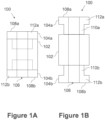
- FIGS 1A and 1B schematically show a tensioner device 100 according to an example embodiment of the present disclosure, in a retracted and extended state, respectively.
- the tensioner device 100 is configured to be arranged on a rod (not shown), and held in place on the rod by surrounding structures, nuts, bolts or similar means.
- the tensioner device 100 comprises three parts: a first part 104a, a second part 104b and a third part 102.
- the first part 104a formed as a hollow bolt 104a, comprises a shaft section 110a and a flange section 112a.
- the shaft section 110a is shown in figure 1B and is, in figure 1A , located radially within the third part 102.
- the second part 104b is similarly formed as a hollow bolt 104b, comprising a shaft section 110b and a flange section 112b.
- the first and second parts 104a, 104b are arranged on opposite sides of the third part 102, such that their respective shaft sections 110a, 110b are arranged towards the other shaft section and configured to be engaged by the third part 102.
- the flange sections 112a, 112b protrude radially out from the shaft sections 110a, 110b and thereby create abutment surfaces 108a, 108b.
- the abutment surfaces 108a and 108b abut an anchor point and a pushing surface (not shown) respectively, thus creating the desired tension within the rod.
- the flange sections extend to the same width as the third part 102.
- the outer radius of the third part 102 is substantially equal to the outer radius of the flange section 112a, 112b of the hollow bolt 104a, 104b.
- the flange section 112a, 112b may extend less than or more than the width of the third part 102, depending on how much contact surface is desired between the abutment surface 108a, 108b and the anchor point and/or pushing surface.
- the third part 102 formed as a nut 102, is arranged between the first part 104a and the second part 104b.
- the shaft section 110a, 110b of the first part 104a and the second part 104b is engaged by and retracts into the third part 102.
- the inner radial surface of the nut 102 is threaded and configured to engage with threads on the outer radial surfaces of the hollow bolts 104a, 104b. The threads are not shown in figures 1A and 1B .
- An opening 106 extends throughout the tensioner device to receive the rod, i.e., extending from an axially outer surface 108a of the first part 104a, to an axially outer surface 108b of the second part 104, and through the third part 102.
- the opening 106 is configured to receive a rod therethrough, so that the tensioner device 100 can be arranged radially around the rod.
- the first part 104a and the second part 104b have been moved linearly away from the third part 102 in opposite directions.
- the first and second parts 104a, 104b extend away from the third part 102.
- This linear movement may result from rotating the third part 102 in a first direction, and this rotation may be translated into the linear movement of the first part 104a and second part 104b, e.g., via the action of threads. Rotating the nut 102 in the opposite direction may thus result in the retraction of the hollow bolts 104a, 104b.
- the nut 102 may be threaded along the axial length of its inner surface, and this threading may be in a single direction.
- the hollow bolts 104a, 104b may then have opposite threading to each other such that the first hollow bolt 104a is right-hand threaded and the second hollow bolt 104b is left-hand threaded, or vice versa. Therefore, a rotation of the nut 102 when engaging the hollow bolts 104a, 104b results in the mutual expansion away from or retraction into the nut 102.
- FIGS 2A and 2B schematically show the tensioner device 100 shown in figures 1A and 1B installed around a composite rod 101, between a first anchor point 101a and a first pushing surface 103c.
- components being referenced with a same numeral as components shown in and described in relation to, e.g., figure 1 may be the same or similar, at least in respect of function, to such components. Hence, such similarly numbered components may not be discussed again in detail.
- the tensioner device 100 comprises a first hollow bolt 104a having a shaft section 110a and a flange section 112a.
- the first hollow bolt 104a is arranged at a first end of a nut 102 (i.e., the third part as described above).
- the shaft section 110a of the first hollow bolt 104a extends within the nut 102, such that the flange section 112a substantially abuts the first end of the nut 102 in the retracted state of the tensioner device 100, as shown in figure 2A .
- a second hollow bolt 104b (i.e., the second part as described above) is arranged.
- the second hollow bolt 104b is formed similarly to the first hollow bolt 104a, comprising a shaft section 110b extending within the nut 102 and a flange section 112b substantially abutting the second end of the nut 102 in the retracted state of the tensioner device 100.
- the hollow bolts 104a, 104b are shown as being substantially similar in this example, in some other examples, the first part 104a and the second part 104b may differ from each other at least in form.
- the tensioner device 100 is arranged on a rod 101.
- the rod 101 extends through the opening 106 of the tensioner device 100.
- a nut 101a, 101b is mounted at each of the ends of the rod 101 .
- first and second anchor points 101a, 101b are formed by nuts threaded onto the rod 101.
- the rod 101 extends through two frame sections 103, 105, which may be parts of a larger structure which the rod 101 is being used to provide additional rigidity or support to.
- the tensioner device 100 is arranged between the top nut 101a on the rod 101, acting as an anchor point on the rod, and the frame structure 103, acting as a first pushing surface.
- the tensioner device In the retracted state of the tensioner device 101, as shown in figure 2A , the tensioner device may abut the frame structure 103 under the action of gravity but may not contact the anchor point 101a.
- the tensioner device 100 In the extended state of the tensioner device 100, as shown in figure 2B , the tensioner device 100 extends and pushes upwards against the nut 101a, acting as a first anchor point, and pushes downwards against the frame structure 103, acting as a first pushing surface. This extension, and thus the pushing action, will cause a displacement X of the nut 101a.
- this displacement X will correspondingly extend the rod 101 and thus tension it, as an opposing end of the rod 101 is anchored via an abutment of a second anchor point 101b against a second pushing surface 105c.
- FIG 3 shows a tensioner device 300a according to another example embodiment of the present disclosure.
- the tensioner device 300a comprises a nut 102 similar to that shown in figures 1 and 2 .
- the tensioner device 300a further comprises a hollow bolt 104a having a shaft section 110a and a flange section 112a, similar to that shown in figures 1 and 2 .
- the flange section has a surface 108a for abutting, or in other words pushing against or applying pressure to an anchor point on a rod.
- the rod and anchor point are not depicted in figure 3 .
- the hollow bolt 104a is positioned at a first end of the nut 102 and arranged so that the shaft section 110a of the hollow bolt 104a extends within the nut 102 in the retracted state of the tensioner device 300a (not shown). In the extended state of the tensioner device 300a, as shown in figure 3 , the shaft section 110a extends out of the nut 102.
- a second hollow bolt 104b is arranged on the opposite end of the nut 102.
- the second hollow bolt 104b may be similarly formed as the first hollow bolt 104a, having a shaft section and a flange section.
- the hollow bolt 104a will extend from the nut 102 when rotating the nut 102, while the hollow bolt 104b will not extend away from the nut 102.
- the extension of the tensioner device 300a will only occur on one end of the nut.
- Both hollow bolts 104a, 104b will apply pressure to the respective anchor point or pushing surface.
- Such an example embodiment may be configured such that the nut 102 engages the first hollow bolt 104a via threads but does not engage the second hollow bolt 104b.
- the inner surface of the nut 102 and the outer surface of the second hollow bolt 104b may be configured to rotate smoothly and/or freely relative to each other, e.g., via a lubricated bearing. Hence, the nut 102 may still be rotated with ease even under tension as the lower surface thereof does not contact the first pushing surface or the first anchor point.
- an opening 106 extends from a first abutment surface 108a of the hollow bolt 110a through the nut 102 and the second hollow bolt 104b, such that the tensioner device 300a can be arranged on a rod.
- the hollow bolt 104a and the second hollow bolt 104b are rigidly connected along an axis of the tensioner device 300a.
- the rigid connection may be implemented by, e.g., a locking pin 306, which extends between the hollow bolts 104a, 104b, and prevents a relative rotation thereof.
- Figure 4 shows a tensioner device 300b according to another exemplary embodiment of the present disclosure.
- Figure 4 essentially shows an opposite arrangement to that of figures 1 to 3 , in that nuts surround a dualshafted bolt rather than bolts retracting into a nut.
- a hollow bolt 302 comprises a flange section 312, and a shaft section 310a, 310b on each side of the flange section 312.
- Each of the shaft sections 310a, 310b is threaded on the outer radial surface, and each of the shaft sections 310a, 310b is threaded in opposite directions.
- shaft section 310a comprises right-handed threads and thus run clockwise
- shaft section 310b comprises left-handed threads and thus run counterclockwise. The threads are not shown in figure 4 .
- each of the shaft section 310a, 310b Threaded on each of the shaft section 310a, 310b is a nut 304a, 304b. Extending through the nuts 304a, 304b and the hollow bolt 302 is an opening 106 configured to receive a rod.
- the nuts 304a, 304b By rotating the hollow bolt 302 in a first direction, the nuts 304a, 304b will linearly extend way from the flange section 312 of the hollow bolt 302. By rotating the hollow bolt 302 in a second direction the nuts 304a, 304b will linearly contract towards the flange section 312 of the hollow bolt 302.
- shaft sections 310a, 310b are threaded in a same direction, and the nuts 304a, 304b have opposite threading.
- Figures 5A and 5B show a perspective view of a tensioner device 400 in a retracted and extended state, respectively, according to an example embodiment of the present disclosure, and figure 5C shows the same tensioner device as that in figures 5A and 5B , in an exploded view.
- the tensioner device 400 comprises a nut 102 with a threaded inside.
- the threaded inside is not shown in figures 5A-C .
- the nut 102 further comprises engagement portions 404 configured to receive a tool, arranged around the circumference of the nut 102. The tool is used to rotate the nut 102, using engagements portions 404.
- the engagement portions 404 are formed as circular holes. However, it should the appreciated that the engagement portions 404 may be protrusions, or have any other shape not shown in figure 5A-C , for example star-shaped, square-shaped, depending on the chosen tool to be used.
- the engagement profile of the nut 102 may instead be a shaping of the nut 102, such as a hexagonal shaping for being engaged by a spanner.
- the engagement portions 404 of the nut 102 are configured to be engaged by a hook spanner or a tommy bar, such that the nut 102 can be rotated without requiring a large clearance space therearound, as the tensioner device 400 may be installed on a rod in a confined space.
- the tensioner device 400 further comprises a hollow bolt 104a arranged on a first side of the nut 102, and a hollow bolt 104b arranged on the opposite side of the nut 102.
- the hollow bolts 104a, 104b comprise a flange section 112 and a shaft section 110, as can be seen in figure 5C , and as discussed above.
- the inside surface of the hollow bolts 104a, 104b comprises two flat portions 402 arranged opposite each other, such that the hollow inside (or opening) 106 is not fully cylindrical or rotationally symmetrical.
- the flat portions 402 advantageously prevent relative rotational movement of the hollow bolts 104a, 104b around the rod and thus facilitates the translation of rotational movement of the nut 102 to a linear movement of the hollow bolts 104a, 104b.
- the flat portions 402 may be viewed as an alternative to the pin 306 shown in figure 3 , or may be used in conjunction with such a pin 306.
- Figures 6A to 6D show various views of the third part 102 (i.e., the nut 102) of the tensioner device as shown in figures 5A to 5C .
- Figure 6A shows the third part 102, also referenced as the nut 102.
- the nut 102 comprises an opening 106, for receiving a rod and the shaft sections of the first and second part, not shown in the figure.
- Around the outer surface 403 of the nut 402 are engagement portions 404, being evenly spaced out in this illustrated example.
- the engagement portions 404 are shown in these figures as being circular holes having a tapered point at their radially inner extreme, and are thereby configured to receive a tool for rotation of the nut 102. However, as discussed above, it should be understood that the engagement portions 404 may be shaped in any suitable way for engaging a tool.
- Figure 6B shows the third part 102 and the engagement portions 404 spaced evenly along an axis B which is axially central, in this example.
- Figure 6C shows a cross section of the third part 102 along axis A as shown in figure 6B .
- the opening 106 extends through the nut 102, and the nut 102 comprises threads on the radially inner surface 402.
- On a first part 402a of the inner radial surface 402 (the top part, if arranged as illustrated in figure 6C ), the threads are threaded in a first direction and on a second part 402b of the inner radial surface 402 (the bottom part, if visualized as illustrated in figure 6C ) the threads are threaded in a second direction, opposite the first direction.
- the threads may extend the full inner radius, or may be interrupted.
- the inner surface 402 may comprise threading only in a single direction throughout.
- Figure 6D shows a top view of the nut 102 in cross section along axis B as shown in figure 6B .
- Extending through the nut 102 is an opening 106 comprising threads on the radially inner surface 402.
- Spaced around the radially outer surface of the nut 102 are engagement portions 404.
- Figures 7A to 7E show various views of the first part and/or the second part 104 of the tensioner device 100 as shown in figures 5A to 5C .
- the first and second parts 104a, 104b may be substantially similar to each other, although inverted relative to each other when installed in use. Thus, only a part 104 is discussed, which could be the first part 104a or the second part 104b.
- Figure 7A shows the part 104, formed as a hollow bolt 104, comprising a shaft section and a flange section (discussed in more detail above).
- a hollow bolt 104 comprising a shaft section and a flange section (discussed in more detail above).
- the hollow bolt extends an opening 106.
- the radially inner surface of 502 the hollow bolt 104 comprises two flat portions, which prevent rotational movement of the hollow bolt 104, and thus facilitates the translation of the rotational movement of the nut to a linear movement of the hollow bolt 104, as discussed above.
- the radially outer surface 504 of the hollow bolt 104 comprises threads configured to engage with a third part, such as the nut shown in figures 6A to 6D .
- Figure 7B shows a side view of the part 104.
- a bevel is provided at the interface between the flange section and the shaft section.
- Figure 7C shows a cross section of the same view as 7B wherein the opening of the part 104 is shown.
- Figure 7D shows a bottom view of the part 104, showing the flange section.
- the hollow opening has an inner surface 502 being partly circular with two flat portions opposite each other, although in alternative examples the portions may be arranged differently, and there may be only one flat portion or more flat portions.
- Figure 7E shows a top view of the part 104, showing the shaft section, i.e., the opposite view of figure 7D .
- the flange section protrudes radially out from the shaft section. Also shown is the opening 106 and the flat portions of the inner radial surface.
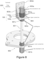
- Figure 8 shows a perspective view of a composite rod 801 installed between two sections of a frame structure 803, 805, having a tensioner device installed therearound, according to an example implementation of the present disclosure.
- the frame structures 803, 805 may form part of a structure for a high power system.
- a first frame structure 803 shaped as a bracket comprises a bottom plate 803a and a back plate 803d configured to be attached to a main frame structure.
- the frame structure 803 also has side plates for keeping the structure stable 803a, 803b, and thus limiting the space for using larger tools when tensioning the rod 801.
- the frame structure 803 is held in place in relation to the rod 801, after tensioning T thereof, by a locking nut 801c arranged on the rod 801 below the bottom plate 803c of the frame structure 803.
- nut 801a, 801b is arranged respectively, serving as anchor points.
- the two sections of the frame structure 803, 805 is locked in place on the rod 801 between each of the nuts 801b, 801a and additional locking nuts 801d, 801c.
- the tensioner device is arranged on the rod 801.
- the nut 801a thus creates a first anchor point for the first part 104a of the tensioner device 100 to abut.
- the bottom plate 803a of the frame structure 803 creates a pushing surface for the second part 104b of the tensioner device 100.
- the first 104a and second 104b part will extend away from the third part 102, pushing against the anchor point (the nut 801a) and the pushing surface (the bottom plate 803c of the frame structure 803).
- This extension, and consequently the pushing will create an extension of the rod and thus tensioning T the rod 801.
- the locking nuts 801c, 801d may be tightened.
- Figure 9 shows a perspective view of the frame structure shown in figure 8 , showing further surrounding components of the frame structure of a high power system.
- Two rods and surrounding structures 800 are provided for reinforcing the illustrated corner of the frame structure 900.
- the rods 800 are arranged between a first frame 909 and a second frame 910, and the tensioning of the rod 801 with the tensioner device 100, will thus tension the first frame 109 and the second frame 910 in relation to each other.
Landscapes
- Engineering & Computer Science (AREA)
- General Engineering & Computer Science (AREA)
- Mechanical Engineering (AREA)
- Bridges Or Land Bridges (AREA)
- Mutual Connection Of Rods And Tubes (AREA)
Abstract
Description
- The present invention relates to structures for supporting converter valve assemblies, for example in high power systems. More particularly, the present invention relates to a tensioner device for tensioning a composite rod that reinforces such structures.
- High power systems comprise converters, the hardware of which (i.e., a set of converter valves) is often arranged in a standing structure. Such standing structures may be placed in spaces that are volumetrically limited and may suffer from frequent seismic activity or other such disturbances, such as on offshore wind farm installations.
- Accordingly, standing structures for converter valve assemblies often require a great amount of structural resilience. While similar structures may exploit high tensile strength materials such as metals, a particular consideration in the context of converter valve assemblies is the need for electrical insulation from the converter valves.
- Hence, it is known to use composite rods, which are not electrically conductive, to reinforce such structures. In practice, a composite rod may be attached between two sections of a standing structure and tensioned to thereby reinforce the connection between said two sections. This is particularly advantageous when torsional forces are expected between said two sections.
- Known means for tensioning composite rods include hydraulic tensioners and turnbuckles. However, there exists a desire to improve means for tensioning composite rods.
- It is realized as a part of the present disclosure that composite rods are increasingly being installed into structures such that there is very limited space around the composite rods. Accordingly, in order to allow for a tensioning of composite rods in a compact space, a more compact tensioner device is required.
- Thus, according to an aspect of the present disclosure, there is provided a tensioner device for tensioning a composite rod, wherein the tensioner device is configured for arranging radially around the composite rod between a first anchor point of the composite rod and a first pushing surface arranged between the first anchor point and a second anchor point of the composite rod.
- That is, the composite rod extends along a length axis, and the composite rod may have integrated or added anchor points at two different sections thereof, e.g., at either end of the composite rod. For example, the composite rod may be threaded at each end and may have a nut affixed at each end, such that the nut presents a surface for pushing against that is fixed relative to the composite rode, referred to herein as an anchor point. In another example, an anchor point may be integrally molded onto an end or intermediate section of the composite rod, depending on the particular implementation.
- The pushing surface is a surface that is separate to the composite rod, such as a surface on a structure which the composite rod is being used to reinforce. That is, the pushing surface is moveable relative to the composite rod. In an example, an end of composite rod may extend through an opening in a bracket, said end comprising an anchor point. The bracket may then form a first pushing surface such that pressure applied between the bracket and the anchor point (i.e., by the tensioning device) tensions the composite rod.
- The tensioner device is thus configured to tension the composite rod by applying pressure between the first anchor point and the first pushing surface. In use, the tensioning device may substantially surround the composite rod, e.g., being threaded onto the composite rod, so as to be arranged radially around the composite rod, between the first anchor point and the first pushing surface. In contrast to prior art devices, the presently disclosed tensioning device is configured to remain in place around the composite rod, rather than being removed after tension has been applied. Hence, the tensioning device may be easily re-tensioned regularly as part of a routine maintenance program.
- The pressure applied by the tensioning device may take the form of a pushing, e.g., such that a top surface and a bottom surface of the tensioning device push outwards away from each other. However, it will be appreciated that the presently disclosed tensioning device may be adapted to tension the composite rod by applying a pulling force instead, if the surrounding structure is adapted accordingly.
- The tensioner device comprises a first part for abutting the first anchor point, a second part for abutting the first pushing surface; and a third part arranged between the first part and the second part. Hence, an assembled tensioner device arranged in use around a composite rod will have axially outermost surfaces formed by the first and second parts, which abut and push against the first anchor point and the first pushing surface, respectively.
- The third part engages at least one of the first part and the second part so as to translate a rotational motion of said third part into a linear motion of said at least one of the first part and the second part away from the third part, to thereby apply the pressure between the first anchor point and the first pushing surface.
- By turning the third part, the first and the second part will extend axially along the rod, pushing against the first anchor point and the first pushing surface. For example, the third part may engage one of the first or second parts, or both, by having a threaded inner surface and the first and/or second parts having a threaded outer surface. Such threaded surfaces may thus enable a translation of a rotational motion of the third part into a linear motion of the first and/or second parts.
- The third part preferably does not, in use, contact the first anchor point or the first pushing surface directly so as not to apply undesirable friction thereagainst - hence, the third part can be allowed to be rotated without undue resistance.
- In an example where only, e.g., the first part is engaged by the third part, the second part may be configured to allow for the rotation of the third part in a substantially unencumbered fashion. For example, the second part and the third part may be coupled by a low-friction rotational bearing. In such an example, the second part will not move linearly away from the third part upon a rotation of the latter.
- In an example configuration of a tensioner device, the first part and/or the second part may be formed as a hollow bolt having a shaft section and a flange section, and the third part may be formed as a nut having a radially inner surface engaging, via threads, the radially outer surface of the shaft section of said hollow bolt. As used here, a 'hollow bolt' may be a bolt or bolt-like component having a recess or through-hole along the axis thereof (e.g., through the center of the rotational axis of the bolt).
- The flange section may extend radially outwards from an end of the shaft section so as to form a surface for pushing or otherwise applying pressure to an anchor point or pushing surface. The construction of the bolts, and in particular the flange section thereof, may preferably be of a material that is able to withstand the expected pressure applied thereto. For example, the bolt(s) may be entirely formed of a resilient metal such as steel, aluminum, or the like.
- The first part and the second part may be formed as hollow bolts having respective shaft sections and flange sections, and the shaft section of the first part may be threaded in an opposite direction to the shaft section of the second part.
- In an alternative configuration, the shaft section of the first part may be threaded in the same direction to the shaft section of the second part, and the third part may comprise a first threaded section engaging the shaft section of the first part and a second threaded section engaging the shaft section of the second part, the first threaded section being threaded in an opposite direction to the second threaded section.
- In a further alternative configuration, the first part and/or the second part may be formed as a nut, and the third part may be formed as a hollow bolt having a pair of shaft sections extending from either end of a flange section, wherein a radially outer surface of at least one of said flange sections engages, via threads, the radially inner surface of said nut.
- The threaded surfaces in such a configuration may be configured to achieve the linear motion of the first and/or second part upon a rotation of the third part. In some examples, a first anchor point may be formed by, e.g., the first part.
- To promote the effective translation of the rotational movement of the third part into a linear motion of the first and/or second parts, it is preferable that the first and second part do not rotate relative to each other and/or the composite rod during rotation of the third part.
- Hence, according to an example refinement of the presently disclosed tensioner device, the first part and the second part are configured to be rotationally fixed relative to each other during rotation of the third part.
- One way to achieve this may be to configure the respective inner surfaces of the first part and the second part to engage the outer surface of the composite rod, e.g., by configuring an outer surface of the composite rod with a flattening or other profile, and configuring an inner surface of the first and second part with a corresponding flattening or other complementary profile.
- An alternative or additional configuration of the first part and the second part to prevent relative rotation may be to rigidly connect these parts along the axis of the tensioner device. For example, the first and second part may be joined by guide pins or similar such components. This approach may advantageously negate a need to configure or adapt an outer surface of the composite rod.
- The third part may be configured to be rotated by a tool. For example, the third part may comprise an engagement profile on the radially outer surface thereof, configured to be engaged by the tool. The tool may be a tommy bar or a hook spanner, and the engagement profile may thus be configured to receive such tools, or whatever tool is intended to rotate the third part. In a particular example, the engagement profile may comprise a plurality of indents spaced apart along the circumference of the third part.
- It will be appreciated that the choice of tool and corresponding engagement profile may advantageously be selected for compactness such that the third part may be rotated effectively without requiring substantial free space therearound. In some examples, the third part may be rotated by hand or by a power tool, and grip onto the third part may be suitably achieved even without an engagement profile, e.g., via frictional and/or magnetic attachment.
- It will be further appreciated that the torque required to rotate the third part may be dependent on the pitch of the threads engaged between the third part and the first and/or second parts (if such threads are used). That is, fine pitched threads may allow for a lesser linear motion of the first and/or second part, but with an increased ease of rotation of the third part, and vice versa.
- The pitch of the thread can readily be converted into amount of extension of the first and/or second part, such as every 120° of rotation being 1 mm of extension. Accordingly, it can be ensured that the composite rod is precisely tensioned, not over- or undertensioned, and that different composite rods in a same structure are tensioned evenly, for example.
- Structures that may benefit from the use of composite rods for reinforcement may include those which carry, e.g., high voltage equipment. Composite rods are not electrically conductive but, when tensioned, can provide a comparable tensile strength to metals.
- Therefore, according to a further aspect of the present disclosure, there is provided a structure for supporting a converter valve assembly, comprising a frame structure, a composite rod arranged to reinforce the frame structure, and the tensioner device substantially as described above, arranged on the composite rod to thereby tension the composite rod.
- Converter valve assemblies may be installed into off-shore wind installations. Such installations may experience significant seismic activity, thus necessitating resilient standing structures for supporting the converter valve assemblies.
- According to the structure described above, the first pushing surface and the second anchor point are fixed to the frame structure, e.g., forming a part of such a standing structure.
- In an example, a bracket may at least partially surround the tensioner device, and may form the first pushing surface. It may be due to such a bracket that a limited space is available around the tensioning device.
- One or more embodiments of the present disclosure will be described, by way of example only, and with reference to the following figures, in which:
-
Figures 1A and 1B schematically show a tensioner device according to an embodiment of the present disclosure, in a retracted and extended state, respectively; -
Figures 2A and 2B schematically show the tensioner device shown infigures 1A and 1B , installed around a composite rod, between a first anchor point and a first pushing surface; -
Figure 3 shows a tensioner device according to another embodiment of the present disclosure; -
Figure 4 shows a tensioner device according to yet another embodiment of the present disclosure; -
Figures 5A and 5B show a perspective view of a tensioner device according to an example embodiment of the present disclosure; -
Figure 5C shows the same tensioner device as that infigures 5A and 5B , in an exploded view; -
Figures 6A to 6D show various views of the third part of the tensioner device as shown infigures 5A to 5C ; -
Figures 7A to 7E show various views of the first part and/or the second part of the tensioner device as shown infigures 5A to 5C ; -
Figure 8 shows a perspective view of a composite rod installed between two sections of a frame structure, having a tensioner device installed therearound, according to an example implementation of the present disclosure; and -
Figure 9 shows a perspective view of the frame structure shown infigure 8 , showing further surrounding components of the frame structure. - The present disclosure is described in the following by way of a number of illustrative examples. It will be appreciated that these examples are provided for illustration and explanation only and are not intended to be limiting on the scope of the present disclosure. Instead, the scope of the present disclosure is defined by the appended claims.
- Furthermore, although embodiments be presented individually for the sake of focused discussion of particular features, it will be recognized that the present disclosure also encompasses combinations of the embodiments described herein.
-
Figures 1A and 1B schematically show atensioner device 100 according to an example embodiment of the present disclosure, in a retracted and extended state, respectively. Thetensioner device 100 is configured to be arranged on a rod (not shown), and held in place on the rod by surrounding structures, nuts, bolts or similar means. Thetensioner device 100 comprises three parts: afirst part 104a, asecond part 104b and athird part 102. - The
first part 104a, formed as ahollow bolt 104a, comprises ashaft section 110a and aflange section 112a. Theshaft section 110a is shown infigure 1B and is, infigure 1A , located radially within thethird part 102. Thesecond part 104b is similarly formed as ahollow bolt 104b, comprising ashaft section 110b and aflange section 112b. The first andsecond parts third part 102, such that theirrespective shaft sections third part 102. - The
flange sections shaft sections abutment surfaces tensioner device 100, in use, theabutment surfaces - In
figures 1A and 1B , the flange sections extend to the same width as thethird part 102. For example, in an example embodiment where the tensioner device is cylindrically shaped, the outer radius of thethird part 102 is substantially equal to the outer radius of theflange section hollow bolt flange section third part 102, depending on how much contact surface is desired between theabutment surface - The
third part 102, formed as anut 102, is arranged between thefirst part 104a and thesecond part 104b. In the retracted state of the tensioner device, shown infigure 1A , theshaft section first part 104a and thesecond part 104b is engaged by and retracts into thethird part 102. As an example implementation of such an engagement, the inner radial surface of thenut 102 is threaded and configured to engage with threads on the outer radial surfaces of thehollow bolts figures 1A and 1B . - An
opening 106 extends throughout the tensioner device to receive the rod, i.e., extending from an axiallyouter surface 108a of thefirst part 104a, to an axiallyouter surface 108b of thesecond part 104, and through thethird part 102. Theopening 106 is configured to receive a rod therethrough, so that thetensioner device 100 can be arranged radially around the rod. - In the extended state of the
tensioner device 100, shown infigure 1B , relative to the retracted state shown infigure 1A , thefirst part 104a and thesecond part 104b have been moved linearly away from thethird part 102 in opposite directions. In other words, the first andsecond parts third part 102. This linear movement may result from rotating thethird part 102 in a first direction, and this rotation may be translated into the linear movement of thefirst part 104a andsecond part 104b, e.g., via the action of threads. Rotating thenut 102 in the opposite direction may thus result in the retraction of thehollow bolts - In an example, the
nut 102 may be threaded along the axial length of its inner surface, and this threading may be in a single direction. Thehollow bolts hollow bolt 104a is right-hand threaded and the secondhollow bolt 104b is left-hand threaded, or vice versa. Therefore, a rotation of thenut 102 when engaging thehollow bolts nut 102. -
Figures 2A and 2B schematically show thetensioner device 100 shown infigures 1A and 1B installed around acomposite rod 101, between afirst anchor point 101a and a first pushingsurface 103c. In these figures and others, components being referenced with a same numeral as components shown in and described in relation to, e.g.,figure 1 , may be the same or similar, at least in respect of function, to such components. Hence, such similarly numbered components may not be discussed again in detail. - The
tensioner device 100, as described above, comprises a firsthollow bolt 104a having ashaft section 110a and aflange section 112a. The firsthollow bolt 104a is arranged at a first end of a nut 102 (i.e., the third part as described above). Theshaft section 110a of the firsthollow bolt 104a extends within thenut 102, such that theflange section 112a substantially abuts the first end of thenut 102 in the retracted state of thetensioner device 100, as shown infigure 2A . - At a second end of the
nut 102, opposite to the first end, a secondhollow bolt 104b (i.e., the second part as described above) is arranged. The secondhollow bolt 104b is formed similarly to the firsthollow bolt 104a, comprising ashaft section 110b extending within thenut 102 and aflange section 112b substantially abutting the second end of thenut 102 in the retracted state of thetensioner device 100. Although thehollow bolts first part 104a and thesecond part 104b may differ from each other at least in form. - The
tensioner device 100 is arranged on arod 101. In other words, therod 101 extends through theopening 106 of thetensioner device 100. At each of the ends of therod 101 anut second anchor points rod 101. Therod 101 extends through twoframe sections rod 101 is being used to provide additional rigidity or support to. - In the illustrated example, the
tensioner device 100 is arranged between thetop nut 101a on therod 101, acting as an anchor point on the rod, and theframe structure 103, acting as a first pushing surface. - In the retracted state of the
tensioner device 101, as shown infigure 2A , the tensioner device may abut theframe structure 103 under the action of gravity but may not contact theanchor point 101a. In the extended state of thetensioner device 100, as shown infigure 2B , thetensioner device 100 extends and pushes upwards against thenut 101a, acting as a first anchor point, and pushes downwards against theframe structure 103, acting as a first pushing surface. This extension, and thus the pushing action, will cause a displacement X of thenut 101a. As thenut 101a is mounted to therod 101, this displacement X will correspondingly extend therod 101 and thus tension it, as an opposing end of therod 101 is anchored via an abutment of asecond anchor point 101b against a second pushingsurface 105c. -
Figure 3 shows atensioner device 300a according to another example embodiment of the present disclosure. Thetensioner device 300a comprises anut 102 similar to that shown infigures 1 and2 . Thetensioner device 300a further comprises ahollow bolt 104a having ashaft section 110a and aflange section 112a, similar to that shown infigures 1 and2 . The flange section has asurface 108a for abutting, or in other words pushing against or applying pressure to an anchor point on a rod. The rod and anchor point are not depicted infigure 3 . - The
hollow bolt 104a is positioned at a first end of thenut 102 and arranged so that theshaft section 110a of thehollow bolt 104a extends within thenut 102 in the retracted state of thetensioner device 300a (not shown). In the extended state of thetensioner device 300a, as shown infigure 3 , theshaft section 110a extends out of thenut 102. - On the opposite end of the
nut 102, a secondhollow bolt 104b is arranged. The secondhollow bolt 104b, may be similarly formed as the firsthollow bolt 104a, having a shaft section and a flange section. However, in this example embodiment, thehollow bolt 104a will extend from thenut 102 when rotating thenut 102, while thehollow bolt 104b will not extend away from thenut 102. In other words, the extension of thetensioner device 300a will only occur on one end of the nut. Bothhollow bolts - Such an example embodiment may be configured such that the
nut 102 engages the firsthollow bolt 104a via threads but does not engage the secondhollow bolt 104b. For example, the inner surface of thenut 102 and the outer surface of the secondhollow bolt 104b may be configured to rotate smoothly and/or freely relative to each other, e.g., via a lubricated bearing. Hence, thenut 102 may still be rotated with ease even under tension as the lower surface thereof does not contact the first pushing surface or the first anchor point. - Similarly to previously described embodiments, an
opening 106 extends from afirst abutment surface 108a of thehollow bolt 110a through thenut 102 and the secondhollow bolt 104b, such that thetensioner device 300a can be arranged on a rod. - According to the example shown in
figure 3 , thehollow bolt 104a and the secondhollow bolt 104b are rigidly connected along an axis of thetensioner device 300a. This prevents thehollow bolts nut 102, and instead provides for the ease of rotational movement of thenut 102, relative to thehollow bolts hollow bolts locking pin 306, which extends between thehollow bolts nut 102 is translated into anything other than a linear motion of thehollow bolt 104a is reduced. -
Figure 4 shows atensioner device 300b according to another exemplary embodiment of the present disclosure.Figure 4 essentially shows an opposite arrangement to that offigures 1 to 3 , in that nuts surround a dualshafted bolt rather than bolts retracting into a nut. That is, infigure 4 , ahollow bolt 302 comprises aflange section 312, and ashaft section flange section 312. Each of theshaft sections shaft sections shaft section 310a comprises right-handed threads and thus run clockwise, whileshaft section 310b comprises left-handed threads and thus run counterclockwise. The threads are not shown infigure 4 . - Threaded on each of the
shaft section nut hollow bolt 302 is anopening 106 configured to receive a rod. - By rotating the
hollow bolt 302 in a first direction, the nuts 304a, 304b will linearly extend way from theflange section 312 of thehollow bolt 302. By rotating thehollow bolt 302 in a second direction the nuts 304a, 304b will linearly contract towards theflange section 312 of thehollow bolt 302. - In another example, the
shaft sections -
Figures 5A and 5B show a perspective view of atensioner device 400 in a retracted and extended state, respectively, according to an example embodiment of the present disclosure, andfigure 5C shows the same tensioner device as that infigures 5A and 5B , in an exploded view. - The
tensioner device 400 comprises anut 102 with a threaded inside. The threaded inside is not shown infigures 5A-C . Thenut 102 further comprisesengagement portions 404 configured to receive a tool, arranged around the circumference of thenut 102. The tool is used to rotate thenut 102, usingengagements portions 404. - In
figures 5A-C , theengagement portions 404 are formed as circular holes. However, it should the appreciated that theengagement portions 404 may be protrusions, or have any other shape not shown infigure 5A-C , for example star-shaped, square-shaped, depending on the chosen tool to be used. The engagement profile of thenut 102 may instead be a shaping of thenut 102, such as a hexagonal shaping for being engaged by a spanner. In preferred embodiments, theengagement portions 404 of thenut 102 are configured to be engaged by a hook spanner or a tommy bar, such that thenut 102 can be rotated without requiring a large clearance space therearound, as thetensioner device 400 may be installed on a rod in a confined space. - The
tensioner device 400 further comprises ahollow bolt 104a arranged on a first side of thenut 102, and ahollow bolt 104b arranged on the opposite side of thenut 102. Thehollow bolts flange section 112 and a shaft section 110, as can be seen infigure 5C , and as discussed above. - According to the illustrated example, the inside surface of the
hollow bolts flat portions 402 arranged opposite each other, such that the hollow inside (or opening) 106 is not fully cylindrical or rotationally symmetrical. Theflat portions 402 advantageously prevent relative rotational movement of thehollow bolts nut 102 to a linear movement of thehollow bolts flat portions 402 may be viewed as an alternative to thepin 306 shown infigure 3 , or may be used in conjunction with such apin 306. -
Figures 6A to 6D show various views of the third part 102 (i.e., the nut 102) of the tensioner device as shown infigures 5A to 5C . -
Figure 6A shows thethird part 102, also referenced as thenut 102. Thenut 102 comprises anopening 106, for receiving a rod and the shaft sections of the first and second part, not shown in the figure. Around theouter surface 403 of thenut 402 areengagement portions 404, being evenly spaced out in this illustrated example. Theengagement portions 404 are shown in these figures as being circular holes having a tapered point at their radially inner extreme, and are thereby configured to receive a tool for rotation of thenut 102. However, as discussed above, it should be understood that theengagement portions 404 may be shaped in any suitable way for engaging a tool. -
Figure 6B shows thethird part 102 and theengagement portions 404 spaced evenly along an axis B which is axially central, in this example. -
Figure 6C shows a cross section of thethird part 102 along axis A as shown infigure 6B . Theopening 106 extends through thenut 102, and thenut 102 comprises threads on the radiallyinner surface 402. On afirst part 402a of the inner radial surface 402 (the top part, if arranged as illustrated infigure 6C ), the threads are threaded in a first direction and on asecond part 402b of the inner radial surface 402 (the bottom part, if visualized as illustrated infigure 6C ) the threads are threaded in a second direction, opposite the first direction. The threads may extend the full inner radius, or may be interrupted. In an alternative arrangement, theinner surface 402 may comprise threading only in a single direction throughout. -
Figure 6D shows a top view of thenut 102 in cross section along axis B as shown infigure 6B . Extending through thenut 102 is anopening 106 comprising threads on the radiallyinner surface 402. Spaced around the radially outer surface of thenut 102 areengagement portions 404. -
Figures 7A to 7E show various views of the first part and/or thesecond part 104 of thetensioner device 100 as shown infigures 5A to 5C . As discussed above, the first andsecond parts part 104 is discussed, which could be thefirst part 104a or thesecond part 104b. -
Figure 7A shows thepart 104, formed as ahollow bolt 104, comprising a shaft section and a flange section (discussed in more detail above). Through the hollow bolt extends anopening 106. The radially inner surface of 502 thehollow bolt 104 comprises two flat portions, which prevent rotational movement of thehollow bolt 104, and thus facilitates the translation of the rotational movement of the nut to a linear movement of thehollow bolt 104, as discussed above. The radiallyouter surface 504 of thehollow bolt 104 comprises threads configured to engage with a third part, such as the nut shown infigures 6A to 6D . -
Figure 7B shows a side view of thepart 104. In this example, a bevel is provided at the interface between the flange section and the shaft section. -
Figure 7C shows a cross section of the same view as 7B wherein the opening of thepart 104 is shown. -
Figure 7D shows a bottom view of thepart 104, showing the flange section. The hollow opening has aninner surface 502 being partly circular with two flat portions opposite each other, although in alternative examples the portions may be arranged differently, and there may be only one flat portion or more flat portions. -
Figure 7E shows a top view of thepart 104, showing the shaft section, i.e., the opposite view offigure 7D . The flange section protrudes radially out from the shaft section. Also shown is theopening 106 and the flat portions of the inner radial surface. -
Figure 8 shows a perspective view of acomposite rod 801 installed between two sections of aframe structure frame structures - A
first frame structure 803 shaped as a bracket comprises abottom plate 803a and aback plate 803d configured to be attached to a main frame structure. Theframe structure 803 also has side plates for keeping the structure stable 803a, 803b, and thus limiting the space for using larger tools when tensioning therod 801. In this example, theframe structure 803 is held in place in relation to therod 801, after tensioning T thereof, by a lockingnut 801c arranged on therod 801 below thebottom plate 803c of theframe structure 803. - At each end of the
rod 801 anut frame structure rod 801 between each of the nuts 801b, 801a andadditional locking nuts - Between the
nut 801a and thebottom plate 803c of theframe structure 803 the tensioner device is arranged on therod 801. Thenut 801a thus creates a first anchor point for thefirst part 104a of thetensioner device 100 to abut. Thebottom plate 803a of theframe structure 803 creates a pushing surface for thesecond part 104b of thetensioner device 100. By rotating thethird part 102 of thetensioner device 100, the first 104a and second 104b part will extend away from thethird part 102, pushing against the anchor point (thenut 801a) and the pushing surface (thebottom plate 803c of the frame structure 803). This extension, and consequently the pushing, will create an extension of the rod and thus tensioning T therod 801. Thereafter, the locking nuts 801c, 801d may be tightened. -
Figure 9 shows a perspective view of the frame structure shown infigure 8 , showing further surrounding components of the frame structure of a high power system. Two rods and surroundingstructures 800, as shown infigure 8 , are provided for reinforcing the illustrated corner of theframe structure 900. Therods 800 are arranged between afirst frame 909 and asecond frame 910, and the tensioning of therod 801 with thetensioner device 100, will thus tension the first frame 109 and thesecond frame 910 in relation to each other. - While the present disclosure is susceptible to various modifications and alternative forms, specific embodiments are shown and described above by way of example in relation to the drawings, with a view to clearly explaining the various advantageous aspects of the present disclosure. It should be understood, however, that the detailed description herein and the drawings attached hereto are not intended to limit the disclosure to the particular form disclosed. Rather, the intention is to cover all modifications, equivalents, and alternatives falling within the scope of the following claims.
Claims (12)
- A tensioner device (100) for tensioning a composite rod (101),wherein the tensioner device (100) is configured for arranging radially around the composite rod (101) between a first anchor point (101a) of the composite rod (101) and a first pushing surface (103c) arranged between the first anchor point (101a) and a second anchor point (101b) of the composite rod (101);wherein the tensioner device (100) is configured to tension the composite rod (101) by applying pressure between the first anchor point (101a) and the first pushing surface (103c);wherein the tensioner device (100) comprises:a first part (104a) for abutting the first anchor point (101a);a second part (104b) for abutting the first pushing surface (103c); anda third part (102) arranged between the first part (104a) and the second part (104b), and engaging at least one of the first part (104a) and the second part (104b) so as to translate a rotational motion of said third part (102) into a linear motion of said at least one of the first part (104a) and the second part (104b) away from the third part (102), to thereby apply the pressure between the first anchor point (101a) and the first pushing surface (103c).
- The tensioner device (100) according to claim 1, wherein:the first part (104a) and/or the second part (104b) is formed as a hollow bolt having a shaft section (110a, 110b) and a flange section (112a, 112b); andthe third part (102) is formed as a nut having a radially inner surface (402) engaging, via threads, the radially outer surface (504) of the shaft section (110a, 110b) of said hollow bolt.
- The tensioner device (100) according to claim 2, wherein:the first part (104a) and the second part (104b) are formed as hollow bolts having respective shaft sections (110a, 110b) and flange sections (112a, 112b); andthe shaft section (110a) of the first part (104a) is threaded in an opposite direction to the shaft section (110b) of the second part (104b).
- The tensioner device (100) according to claim 2, wherein:the first part (104a) and the second part (104b) are formed as hollow bolts having respective shaft sections (110a, 110b) and flange sections (112a, 112b);the shaft section (110a) of the first part (104a) is threaded in the same direction to the shaft section (110b) of the second part (104b); andthe third part (102) comprises a first threaded section (402a) engaging the shaft section (110a) of the first part (104a) and a second threaded section (402b) engaging the shaft section (110b) of the second part (104b), the first threaded section (402a) being threaded in an opposite direction to the second threaded section (402b).
- The tensioner device according to claim 1, wherein:the first part and/or the second part is formed as a nut; andthe third part is formed as a hollow bolt having a pair of shaft sections extending from either end of a flange section, wherein a radially outer surface of at least one of said flange sections engages, via threads, the radially inner surface of said nut.
- The tensioner device according to any preceding claim, wherein:
the first part and the second part are configured to be rotationally fixed relative to each other during rotation of the third part. - The tensioner device according to claim 6, wherein:
the respective inner surfaces of the first part and the second part are configured to engage the outer surface of the composite rod. - The tensioner device according to claim 6, wherein:
the first part and the second part are rigidly connected along the axis of the tensioner device. - The tensioner device according to any preceding claim, wherein:
the third part is configured to be rotated by a tool. - The tensioner device according to claim 9, wherein:
the third part comprises an engagement profile (403) on the radially outer surface (404) thereof, configured to be engaged by the tool. - A structure for supporting a converter valve assembly, comprising:a frame structure;a composite rod arranged to reinforce the frame structure; andthe tensioner device according to any preceding claim, arranged on the composite rod to thereby tension the composite rod;wherein the first pushing surface and the second anchor point are fixed to the frame structure.
- The structure according to claim 11, further comprising:a bracket at least partially surrounding the tensioner device;wherein the bracket forms the first pushing surface.
Priority Applications (4)
| Application Number | Priority Date | Filing Date | Title |
|---|---|---|---|
| EP23171874.3A EP4459136A1 (en) | 2023-05-05 | 2023-05-05 | Tensioner device |
| CN202480004686.3A CN120153179B (en) | 2023-05-05 | 2024-04-29 | Structure for supporting converter valve assembly |
| US19/127,046 US20260002559A1 (en) | 2023-05-05 | 2024-04-29 | Tensioner device |
| PCT/EP2024/061773 WO2024231162A1 (en) | 2023-05-05 | 2024-04-29 | Structure for supporting a converter valve assembly |
Applications Claiming Priority (1)
| Application Number | Priority Date | Filing Date | Title |
|---|---|---|---|
| EP23171874.3A EP4459136A1 (en) | 2023-05-05 | 2023-05-05 | Tensioner device |
Publications (1)
| Publication Number | Publication Date |
|---|---|
| EP4459136A1 true EP4459136A1 (en) | 2024-11-06 |
Family
ID=86330240
Family Applications (1)
| Application Number | Title | Priority Date | Filing Date |
|---|---|---|---|
| EP23171874.3A Pending EP4459136A1 (en) | 2023-05-05 | 2023-05-05 | Tensioner device |
Country Status (4)
| Country | Link |
|---|---|
| US (1) | US20260002559A1 (en) |
| EP (1) | EP4459136A1 (en) |
| CN (1) | CN120153179B (en) |
| WO (1) | WO2024231162A1 (en) |
Citations (3)
| Publication number | Priority date | Publication date | Assignee | Title |
|---|---|---|---|---|
| US2678226A (en) * | 1950-12-27 | 1954-05-11 | Ben F White | Turnbuckle |
| FR2668558A1 (en) * | 1990-10-29 | 1992-04-30 | Arteon Marcel | Connection device for joining two bars end to end |
| KR102431360B1 (en) * | 2020-08-05 | 2022-08-11 | 주식회사 유승이피씨 | Post structure for soundproof walls |
Family Cites Families (3)
| Publication number | Priority date | Publication date | Assignee | Title |
|---|---|---|---|---|
| DE102016205086A1 (en) * | 2016-03-29 | 2017-10-05 | Aktiebolaget Skf | Rod clamping device and assembly method for such a device on a rod |
| NO344596B1 (en) * | 2016-09-05 | 2020-02-03 | Designbanken As | Bolt tensioning assembly and method for tensioning of a bolt |
| GB2579578A (en) * | 2018-12-04 | 2020-07-01 | Tentec Ltd | Hydraulic tensioner and method of tensioning |
-
2023
- 2023-05-05 EP EP23171874.3A patent/EP4459136A1/en active Pending
-
2024
- 2024-04-29 CN CN202480004686.3A patent/CN120153179B/en active Active
- 2024-04-29 US US19/127,046 patent/US20260002559A1/en active Pending
- 2024-04-29 WO PCT/EP2024/061773 patent/WO2024231162A1/en not_active Ceased
Patent Citations (3)
| Publication number | Priority date | Publication date | Assignee | Title |
|---|---|---|---|---|
| US2678226A (en) * | 1950-12-27 | 1954-05-11 | Ben F White | Turnbuckle |
| FR2668558A1 (en) * | 1990-10-29 | 1992-04-30 | Arteon Marcel | Connection device for joining two bars end to end |
| KR102431360B1 (en) * | 2020-08-05 | 2022-08-11 | 주식회사 유승이피씨 | Post structure for soundproof walls |
Also Published As
| Publication number | Publication date |
|---|---|
| WO2024231162A1 (en) | 2024-11-14 |
| US20260002559A1 (en) | 2026-01-01 |
| CN120153179B (en) | 2026-03-17 |
| CN120153179A (en) | 2025-06-13 |
Similar Documents
| Publication | Publication Date | Title |
|---|---|---|
| EP2501640B1 (en) | Base frame for a lifting apparatus, especially a cable traction mechanism | |
| RU2472982C2 (en) | Improved nut and bolt | |
| US7467783B2 (en) | Tensioning apparatus and method | |
| DE102011017801B4 (en) | Wind turbine with a plurality of displacement units for mounting or dismounting of rotor blades and method thereof | |
| EP0354363A2 (en) | Clamping device with a screwed bush | |
| NL2004126C2 (en) | COMPOSITION OF CONFIRMATION ELEMENTS, TORQUE ROD, AND NUT SHAPED BY A TORQUE ROD AND A NUT. | |
| MXPA04010376A (en) | Washer, fastener provided with a washer, method of and power tool for fastening objects. | |
| EP4286264A2 (en) | Drive unit of a vehicle that can be operated by muscle power and/or motor power | |
| US20260002559A1 (en) | Tensioner device | |
| AT508174B1 (en) | CONNECTION DEVICE | |
| AU2016277543A1 (en) | Locking washer for brace members | |
| EP4299501A1 (en) | Connecting device for connecting boom segments of a boom of a tower crane | |
| EP4288670B1 (en) | Drive arrangement | |
| EP2395249A1 (en) | Segmented thread and connecting arrangement | |
| EP0337415B1 (en) | Sound damping element | |
| US20090178352A1 (en) | Composite Structural Member | |
| DE10161026A1 (en) | Self-locking screw element | |
| DE102008024861A1 (en) | Climbing attachment system for attachment of e.g. climbing platform, to pillar, has carrier enclosing carrying structure, where system is supported friction conclusively at carrying structure in vertical direction | |
| DE102022001035B3 (en) | Universal adapter for mounting on a fixed point of a vehicle | |
| CN120057127B (en) | Connection structure based on modularization aluminium automobile body assembly | |
| DE3731682C2 (en) | Fastening device with rubber damper | |
| WO2024003167A1 (en) | Connection device for connecting jib segments of a jib of a tower crane | |
| CN215890665U (en) | Anti-loosening device for servo oil cylinder | |
| CN112304750B (en) | Rope stretching test device and rope stretching method thereof | |
| EP4238860A2 (en) | Drive assembly |
Legal Events
| Date | Code | Title | Description |
|---|---|---|---|
| PUAI | Public reference made under article 153(3) epc to a published international application that has entered the european phase |
Free format text: ORIGINAL CODE: 0009012 |
|
| STAA | Information on the status of an ep patent application or granted ep patent |
Free format text: STATUS: THE APPLICATION HAS BEEN PUBLISHED |
|
| AK | Designated contracting states |
Kind code of ref document: A1 Designated state(s): AL AT BE BG CH CY CZ DE DK EE ES FI FR GB GR HR HU IE IS IT LI LT LU LV MC ME MK MT NL NO PL PT RO RS SE SI SK SM TR |
|
| STAA | Information on the status of an ep patent application or granted ep patent |
Free format text: STATUS: REQUEST FOR EXAMINATION WAS MADE |
|
| 17P | Request for examination filed |
Effective date: 20250110 |
|
| GRAJ | Information related to disapproval of communication of intention to grant by the applicant or resumption of examination proceedings by the epo deleted |
Free format text: ORIGINAL CODE: EPIDOSDIGR1 |
|
| GRAP | Despatch of communication of intention to grant a patent |
Free format text: ORIGINAL CODE: EPIDOSNIGR1 |
|
| GRAP | Despatch of communication of intention to grant a patent |
Free format text: ORIGINAL CODE: EPIDOSNIGR1 |
|
| STAA | Information on the status of an ep patent application or granted ep patent |
Free format text: STATUS: GRANT OF PATENT IS INTENDED |
|
| RIC1 | Information provided on ipc code assigned before grant |
Ipc: F16B 5/02 20060101AFI20251113BHEP Ipc: F16B 7/06 20060101ALI20251113BHEP Ipc: F16B 31/04 20060101ALI20251113BHEP Ipc: F16B 35/04 20060101ALN20251113BHEP |
|
| RIC1 | Information provided on ipc code assigned before grant |
Ipc: F16B 5/02 20060101AFI20251124BHEP Ipc: F16B 7/06 20060101ALI20251124BHEP Ipc: F16B 31/04 20060101ALI20251124BHEP Ipc: F16B 35/04 20060101ALN20251124BHEP |
|
| INTG | Intention to grant announced |
Effective date: 20251208 |
|
| GRAS | Grant fee paid |
Free format text: ORIGINAL CODE: EPIDOSNIGR3 |