EP4459024A1 - Panel, panel component of household appliance, and household appliance - Google Patents
Panel, panel component of household appliance, and household appliance Download PDFInfo
- Publication number
- EP4459024A1 EP4459024A1 EP24166368.1A EP24166368A EP4459024A1 EP 4459024 A1 EP4459024 A1 EP 4459024A1 EP 24166368 A EP24166368 A EP 24166368A EP 4459024 A1 EP4459024 A1 EP 4459024A1
- Authority
- EP
- European Patent Office
- Prior art keywords
- panel
- display area
- display
- outer layer
- inner layer
- Prior art date
- Legal status (The legal status is an assumption and is not a legal conclusion. Google has not performed a legal analysis and makes no representation as to the accuracy of the status listed.)
- Pending
Links
Images






Classifications
-
- D—TEXTILES; PAPER
- D06—TREATMENT OF TEXTILES OR THE LIKE; LAUNDERING; FLEXIBLE MATERIALS NOT OTHERWISE PROVIDED FOR
- D06F—LAUNDERING, DRYING, IRONING, PRESSING OR FOLDING TEXTILE ARTICLES
- D06F34/00—Details of control systems for washing machines, washer-dryers or laundry dryers
- D06F34/28—Arrangements for program selection, e.g. control panels therefor; Arrangements for indicating program parameters, e.g. the selected program or its progress
-
- G—PHYSICS
- G09—EDUCATION; CRYPTOGRAPHY; DISPLAY; ADVERTISING; SEALS
- G09F—DISPLAYING; ADVERTISING; SIGNS; LABELS OR NAME-PLATES; SEALS
- G09F13/00—Illuminated signs; Luminous advertising
- G09F13/04—Signs, boards or panels, illuminated from behind the insignia
- G09F13/0418—Constructional details
-
- D—TEXTILES; PAPER
- D06—TREATMENT OF TEXTILES OR THE LIKE; LAUNDERING; FLEXIBLE MATERIALS NOT OTHERWISE PROVIDED FOR
- D06F—LAUNDERING, DRYING, IRONING, PRESSING OR FOLDING TEXTILE ARTICLES
- D06F34/00—Details of control systems for washing machines, washer-dryers or laundry dryers
- D06F34/28—Arrangements for program selection, e.g. control panels therefor; Arrangements for indicating program parameters, e.g. the selected program or its progress
- D06F34/32—Arrangements for program selection, e.g. control panels therefor; Arrangements for indicating program parameters, e.g. the selected program or its progress characterised by graphical features, e.g. touchscreens
-
- F—MECHANICAL ENGINEERING; LIGHTING; HEATING; WEAPONS; BLASTING
- F24—HEATING; RANGES; VENTILATING
- F24C—DOMESTIC STOVES OR RANGES ; DETAILS OF DOMESTIC STOVES OR RANGES, OF GENERAL APPLICATION
- F24C7/00—Stoves or ranges heated by electric energy
- F24C7/08—Arrangement or mounting of control or safety devices
- F24C7/082—Arrangement or mounting of control or safety devices on ranges, e.g. control panels, illumination
-
- G—PHYSICS
- G09—EDUCATION; CRYPTOGRAPHY; DISPLAY; ADVERTISING; SEALS
- G09F—DISPLAYING; ADVERTISING; SIGNS; LABELS OR NAME-PLATES; SEALS
- G09F13/00—Illuminated signs; Luminous advertising
- G09F13/04—Signs, boards or panels, illuminated from behind the insignia
- G09F13/08—Signs, boards or panels, illuminated from behind the insignia using both translucent and non-translucent layers
-
- G—PHYSICS
- G09—EDUCATION; CRYPTOGRAPHY; DISPLAY; ADVERTISING; SEALS
- G09F—DISPLAYING; ADVERTISING; SIGNS; LABELS OR NAME-PLATES; SEALS
- G09F9/00—Indicating arrangements for variable information in which the information is built-up on a support by selection or combination of individual elements
- G09F9/30—Indicating arrangements for variable information in which the information is built-up on a support by selection or combination of individual elements in which the desired character or characters are formed by combining individual elements
Definitions
- Embodiments of the present invention relate to the field of household appliances, and in particular, to a panel, a panel component of a household appliance, and a household appliance.
- the panel component may be configured to control the household appliance, and display related content such as use states and program options of the household appliance.
- the panel component mainly displays content through a panel.
- the existing panel has a poor display effect.
- An object of the present invention is to provide a new panel with a desirable display effect, a panel component of a household appliance, and a household appliance.
- an embodiment of the present invention provides a panel, applied to a panel component of a household appliance.
- the panel component includes a main body and a display module.
- the display module includes one or more display objects configured to be illuminated or extinguished.
- the panel is connected to the main body and is configured to block the display module.
- the panel includes: an outer layer, including a display area and a non-display area, where light emitted when the display object is illuminated is allowed to be transmitted out of the display area; and an inner layer, located on a back side of the outer layer to block the light emitted when the display object is illuminated from being transmitted out of the non-display area.
- the outer layer is configured as the display area and the non-display area.
- the outer layer of the panel is light-transmissive, and when the display object is illuminated, the light emitted when the display object is illuminated passes through the outer layer. Therefore, a user can see the illuminate display object through the display area of the panel, so that the display area can display the display object. Since the inner layer can block the light emitted when the display object is illuminated from being transmitted out of the non-display area, the light emitted when the display object is illuminated can be gathered in the display area to avoid loss of the light. In this way, a display brightness of the display object is ensured, and the light emitted when the display object is illuminated is prevented from being transmitted out of only the display area, thereby improving a display effect of the panel.
- the display area of the inner layer close to the outer layer has a first transition section, and a thickness of the first transition section is less than a thickness of another area of the inner layer.
- the first transition section may enable the inner layer close to the display area to naturally and smoothly transition to avoid a sudden change in a wall thickness, so as to reduce or even hopefully eliminate a visual difference caused by the sudden change in the wall thickness, thereby improving the display effect.
- poor appearance caused by shrinkage as a result of the change in the wall thickness may also be avoided, to ensure the appearance effect of the panel.
- a ratio of a length of the first transition section to the thickness of the first transition section is greater than a preset ratio, and the length of the first transition section is a length in a length direction of the panel.
- the outer layer has a second transition section matching the first transition section, and a thickness of the second transition section gradually decreases in a direction from the display area to a point away from the display area. In this way, a total thickness of the panel may be ensured to satisfy a total thickness limit of a space of the panel component.
- an end of the second transition section away from the display area is provided with a first curved transition surface, and/or an end of the second transition section close to the display area is provided with a second curved transition surface, so that a transition between the two ends of the second transition section and a nearby area is relatively smooth, thereby further reducing a probability of a shrinkage phenomenon as a result of the change in the wall thickness.
- the first curved transition surface is an arc-shaped transition surface
- the second curved transition surface is an arc-shaped transition surface
- the inner layer is arranged at least on a periphery of the display area.
- an arrangement area of the inner layer may be reduced while the inner layer blocks the light emitted when the display object is illuminated from being transmitted out of the non-display area, which facilitates a reduction in costs.
- the inner layer covers the non-display area of the outer layer, which helps ensure consistency of a uniform color of the non-display area of the panel and improve an overall appearance effect of the non-display area of the panel.
- the inner layer protrudes from the back side of the outer layer or is flush with the back side of the outer layer.
- At least part of an edge of the outer layer has a protrusion, and the protrusion protrudes from the back side of the outer layer to block the inner layer.
- integrity of the panel may be better, and the appearance effect of the panel may also be improved.
- the inner layer is opaque or has a transparency less than a set light transmission threshold.
- the outer layer is obtained by injection molding on the inner layer, or the inner layer is obtained by injection molding on the outer layer.
- the display area and the non-display area are made of a same material and are translucent, and the outer layer is further configured to shield the display module when the display object is extinguished.
- the display module is shielded through the display area, so that the display module behind the display area is not easily perceived by the user or is not displayed.
- the non-display area and the display area are made of a same material and are translucent, so that the inner layer behind the non-display area is not easily perceived by the user or is not displayed, and the display area and the non-display area of the panel can present a uniform display effect as a whole, thereby improving the uniform display effect of the panel.
- An embodiment of the present invention further provides a panel component of a household appliance, including: a main body; and a display module, connected to the main body and including one or more display objects configured to be illuminated or extinguished, and further including any panel described above, where the panel is connected to the main body.
- a back side of the inner layer is provided with a mounting structure, and the mounting structure is configured to connect the panel to the main body.
- the inner layer may block some structures located below the inner layer from being displayed or perceived, and has a better visual effect.
- the mounting structure is located on a back side of the inner layer, which helps implement assembly of a front side of the panel, satisfy assembly requirements of the front side, and improve convenience of the mounting.
- the present invention further provides a household appliance, including any panel component described above.
- FIG. 1 is a schematic structural diagram of a panel according to an embodiment of the present invention.
- FIG. 2 is a left view of FIG. 1 .
- FIG. 3 is a top view of FIG. 1 .
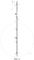
- FIG. 4 is a cross-sectional view taken along line B-B in FIG. 1 .
- FIG. 5 is a partial schematic structural diagram of E in FIG. 4 .
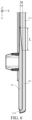
- FIG. 6 is a partial schematic structural diagram of F in FIG. 5 .
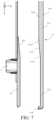
- FIG. 7 is an exploded view of FIG. 6 .
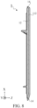
- FIG. 8 is a cross-sectional view taken along line C-C in FIG. 1 .
- FIG. 9 is a cross-sectional view taken along line D-D in FIG. 1 .
- a specific structure of a panel 1 is described below with reference to FIG. 1 to FIG. 9 .
- X represents a thickness direction of the panel 1
- Y represents a length direction of the panel 1
- Z represents a width direction of the panel 1.
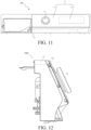
- FIG. 11 is a schematic structural diagram of a panel component according to an embodiment of the present invention from a perspective.
- FIG. 12 is a left view of FIG. 11 .
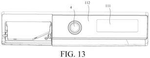
- FIG. 13 is a schematic structural diagram of FIG. 11 from another perspective.
- FIG. 13 is illustrated from a viewpoint of a user facing the panel component 100 with a line of sight perpendicular to the panel 1.
- the panel component 100 includes a main body 3 and a display module (not shown in the figure).
- the display module includes one or more display objects configured to be illuminated or extinguished.
- the panel 1 is connected to the main body 3 and configured to block the display module.
- the panel 1 includes an outer layer 11 and an inner layer 12.
- the outer layer 11 may include a display area 111 and a non-display area 112. Light emitted when the display object is illuminated is allowed to be transmitted out of the display area 111.
- the inner layer 12 is located on a back side 11b of the outer layer 11 to block the light emitted when the display object is illuminated from being transmitted out of the non-display area 112.
- the display object may be a character, a pattern, or a light-emitting component.
- the display object such as the character or the pattern may be illuminated by turning on the light-emitting component (such as a light-emitting diode) corresponding to the character or the pattern, so that the panel component 100 can display the character or the pattern.
- the display object is a light-emitting component, requirements of some scenes for ambient lighting may be satisfied, for example, a requirement that a light ring should be emitted around a knob. As an example, a ring light is arranged around a knob 4.
- a shape of the display area 11 may be a rectangle, a circle, or a ring. It may be understood that the shape of the display area 11 may also be various other suitable shapes, which is not limited herein.
- a side of the outer layer 11 facing the user is denoted as a front side 11a, and the front side 11a is away from the inner layer 12.
- a side of the outer layer 11 facing away from the user is denoted as the back side 11b, and the back side 11b faces the inner layer 12.
- the outer layer 11 is configured as the display area 111 and the non-display area 112.
- the outer layer 11 of the panel 1 is light-transmissive, and when the display object is illuminated, the light emitted when the display object is illuminated passes through the outer layer 11. Therefore, a user can see the illuminated display object through the display area 111 of the panel 1, so that the display area 111 can display the display object.
- the inner layer 12 can block the light emitted when the display object is illuminated from being transmitted out of the non-display area 112, and the light emitted when the display object is illuminated is gathered in the display area 111, so as to effectively avoid loss of the light. In this way, a display brightness of the display object is ensured, and the light emitted when the display object is illuminated is prevented from being transmitted out of only the display area 111, thereby improving a display effect of the panel 1.
- the display area 111 and the non-display area 112 of the outer layer 11 are made of the same material and are translucent.
- the outer layer 11 is further configured to shield the display module when the display object is extinguished. In this way, when the display object is illuminated, the display area 111 can display the display object. When the display object is turned off, the display module is shielded through the display area 111, so that the display module behind the display area 111 is not easily perceived by the user or is not displayed.
- the non-display area 112 and the display area 111 are made of the same material and are translucent, so that the inner layer 12 behind the non-display area 112 is not easily perceived by the user or is not displayed. Further, the display area 111 and the non-display area 112 of the panel 1 can present a uniform display effect as a whole, and the panel 1 may present a better overall appearance.
- the inner layer 12 is arranged at least on a periphery of the display area 111.
- an area of the non-display area 112 surrounding the display area 111 is provided with the inner layer 12.
- an arrangement area of the inner layer 12 may be reduced while the inner layer 12 blocks the light emitted when the display object is illuminated from being transmitted out of the non-display area 112, which facilitates a reduction in costs.
- the inner layer 12 covers the non-display area 112 of the outer layer 11. In other words, the inner layer 12 is arranged in areas corresponding to the non-display area 112 on the back side 11b of the outer layer 11.
- the display area 111 of the inner layer 12 close to the outer layer 11 has a first transition section 121, and a thickness of the first transition section 121 is less than a thickness of another area of the inner layer 12.
- the arranged first transition section 121 may enable the inner layer 12 close to the display area 111 to naturally and smoothly transition to avoid a sudden change in a wall thickness, so as to reduce or even hopefully eliminate a visual difference caused by the sudden change in the wall thickness, thereby improving the display effect.
- poor appearance caused by shrinkage as a result of the change in the wall thickness may also be avoided, to ensure the appearance effect of the panel 1.
- the thickness of the first transition section 121 of the inner layer 12 gradually increases in a direction away from the display area 111.
- a ratio of a length L of the first transition section 121 to a thickness ⁇ t of the first transition section 121 is greater than a preset ratio, and the length L of the first transition section 121 is a length in a length direction Y of the panel 1.
- the thickness ⁇ t of the first transition section 121 is a thickness in the thickness direction X of the panel 1.
- the preset value is obtained based on factors such as a size of the panel 1, a size of the display area 11, and a size of the inner layer 12.
- the preset value is also related to a mutual pulling force generated between the outer layer 11 and the inner layer 12 due to an injection molding surface during injection molding.
- a value range of the preset ratio is greater than or equal to 5.
- the display area 111 and the non-display area 112 of the outer layer 11 may have the same thickness.
- a thickness of the panel 1 at the area provided with the inner layer 12 may be greater than the thickness at the display area 111.
- the display area 111 and the non-display area 112 of the outer layer 11 may have different thicknesses.
- the thickness of the non-display area 112 is less than the thickness of the display area 111.
- the outer layer 11 has a recessed portion on the back side of the non-display area 112, and the inner layer 12 may be located in the recessed portion.
- a sum of the thicknesses of the inner layer 12 and the non-display area 112 may be less than the thickness of the display area 111, or may be greater than the thickness of the display area 111, and may also be equal to the thickness of the display area 111. In this way, it is helpful to flexibly configure a total thickness of the panel 1, to accommodate total thickness limitations for the panel component 100 in different spaces and improve universality of the panel 1.
- the thickness of the non-display area 112 may alternatively be greater than the thickness of the display area 111 based on requirements of an actual application scenario.
- the outer layer 11 has a second transition section 113 matching the first transition section 121, and a thickness of the second transition section 113 gradually decreases in a direction from the display area 111 to a point away from the display area 111.
- the total thickness of the panel 1 may be ensured to satisfy a total thickness restriction of a space of the panel component 100.
- the second transition section 113 is located at a position of the non-display area 112 close to the display area 111.
- contact surfaces of the first transition section 121 and the second transition section 113 match each other to improve a degree of fitting between the first transition section 121 and the second transition section 113.
- an end of the second transition section 113 away from the display area 111 is provided with a first curved transition surface 1131.
- an end of the second transition section 113 close to the display area 111 is provided with a second curved transition surface 1132.
- an end of the second transition section 113 away from the display area 111 is provided with a first curved transition surface 1131, and an end of the second transition section 113 close to the display area 111 is provided with a second curved transition surface 1132.
- One of the first curved transition surface 1131 and the second curved transition surface 1132 is an arc-shaped transition surface, or the first curved transition surface 1131 and the second curved transition surface 1132 are both arc-shaped transition surfaces, which further reduces a probability of a shrinkage phenomenon as a result of the change in the wall thickness.
- the thicknesses of the outer layer 11 and the inner layer 12 may be configured based on thickness requirements of the outer layer 11 and the inner layer 12.
- the first transition section 121 may be configured on the inner layer 12, or the first transition section 121 may not be configured.
- the second transition section 113 may be configured on the outer layer 11, or the second transition section 113 may not be configured.
- the inner layer 12 protrudes from a back side 11b of the outer layer 11 or is flush with the back side 11b of the outer layer 11.
- a protrusion 114 in a thickness direction X of the outer layer 11, at least part of an edge of the outer layer 11 has a protrusion 114, and the protrusion 114 protrudes from the back side 11b of the outer layer 11 to block the inner layer 12.
- the protrusion 114 shields a side wall 122 of the inner layer 12 in the thickness direction X. In this way, integrity of the panel 1 may be better, and the appearance effect of the panel 1 may also be improved.
- the protrusion 114 covers the corresponding side wall 122.
- the inner layer 12 is opaque or has a transparency less than a set light transmission threshold, to improve an effect of blocking the light emitted when the display object is illuminated from being transmitted out of the non-display area 112.
- the inner layer 12 may be made of black or other colored plastic.
- the inner layer 12 is made of an acrylonitrile-butadiene-styrene copolymer (ABS), an ABS engineering plastic (also referred to as an engineering plastic alloy, a copolymer of polycarbonate (PC) and ABS PC+ABS), polystyrene (PS), or the like.
- ABS acrylonitrile-butadiene-styrene copolymer
- PC polycarbonate
- PS polystyrene
- the outer layer 11 is transparent or translucent.
- the outer layer 11 may be made of a transparent material or a translucent material.
- the outer layer 11 may be made of acrylic (also referred to as PMMA or organic glass), PC, and other types of light-transmissive window plastics.
- Colors of the outer layer 11 and the inner layer 12 may be the same or different. Hardness of the outer layer 11 and the inner layer 12 may be the same or different, which may be configured based on overall appearance requirements and assembly requirements of the panel 1.
- the inner layer 12 is made of a black opaque material
- the outer layer 11 is made of a black translucent material. In this way, during display of the illuminated display object in the display area 111, when the display object is extinguished, the panel 11 may present a uniform black display effect.
- IMD inmode decoration
- the IMD usually mainly includes in molding label (IML), in-mold film (IMF), in-mold roller (IMR), and the like.
- IML molding label
- IMF in-mold film
- IMR in-mold roller
- a printed film is fed into a mold in various forms, and transfer of a multi-layer ink print or film attachment is performed on a part surface to realize a window decoration or window display effect.
- the panel manufactured by using the IMD process may realize an appearance effect of different colors, but it results in a surplus display effect for a window display part or a surplus overall opaque display effect that can be realized by using black or plastic particles.
- complexity and costs of the panel are both relatively high, and therefore the display effect and the costs of the panel cannot be desirably taken into account.
- the panel 1 may be obtained by injection molding.
- the panel may be obtained by injection molding by using the same set of molds.
- the panel 1 is obtained by injection molding, and the process is simple, which helps reduce costs.
- the panel obtained by injection molding can reduce costs while realizing the same function and helping ensure the display effect.
- the inner layer 12 is obtained by injection molding on the outer layer 11.
- the outer layer 11 may be obtained by injection molding, and then the inner layer 12 is injection molded on the outer layer 11, so as to obtain the panel 1.
- the outer layer 11 is obtained by injection molding on the inner layer 12.
- the inner layer 12 may be obtained by injection molding, and then the outer layer 11 is obtained by injection molding on the inner layer 12, so as to obtain the panel 1.
- a sequence of injection molding for the outer layer 11 and the inner layer 12 may be selected based on characteristics such as a melting temperature of the material and design of a mold.
- the panel 1 provided in the embodiment of the present invention may be applied to the panel component 100 of the household appliance such as a control panel of a washing machine, a control panel of a clothes dryer, and a control panel of a washing and drying machine, to satisfy a window display function of the panel component 100.
- the panel component 100 may include a main body 3, a display module (not shown in the figure), and a panel 1.
- the display module is connected to the main body 3.
- the display module includes one or more display objects configured to be illuminated or extinguished.
- the panel 1 is connected to the main body 3.
- the panel 1 may be the panel 1 provided in any of the foregoing embodiments.
- the back side of the inner layer 12 is provided with a positioning portion 2, and correspondingly, a positioning and mating portion is arranged on the main body 3.
- the positioning portion 2 mates with the positioning and mating portion to implement mounting and positioning, so as to improve mounting convenience and mounting accuracy of the panel 1.
- Specific structures of the positioning portion 2 and the positioning and mating portion are not limited herein, as long as the positioning portion and the positioning and mating portion may match each other to implement mounting and positioning.
- one of the positioning portion 2 and the positioning and mating portion is a positioning protrusion, and the other is a positioning groove.
- one of the positioning portion 2 and the positioning and mating portion is a positioning post
- the other is a protrusion having an accommodating cavity
- the positioning post is inserted into the accommodating cavity of the protrusion.
- the back side of the inner layer 12 may also be provided with a connection structure such as a hook, a glue tank, or an ultrasonic welding rib.
- the ultrasonic welding rib is configured to ultrasonically weld the panel 1 to the main body 3.
- the connection structure is arranged on the back side of the inner layer 12, which can help reduce costs of the panel 1, realize assembly of a front side of the panel 1 to the main body 3, satisfy the assembly requirements of the front side, and improve the mounting convenience of the panel 1.
- the connection structure does not need to be arranged on the outer layer 11, it is helpful to enable a boundary of the outer layer 11 to extend to an outermost side of the panel 1, to achieve a window display effect with a maximum boundary, and realize better aesthetics.
- the positioning portion 2 is arranged on the back side of the inner layer 12, the positioning portion 2, another structure such as the hook, the glue tank, or the ultrasonic welding rib arranged on the back side of the inner layer 12, and some structures of the household appliance located below the inner layer 12 may be shielded and hidden through the inner layer 12, so that it is not easy for users to perceive from the front side of the panel 1, and the overall appearance effect of the panel 1 is improved.
- An embodiment of the present invention further provides a household appliance, including the panel component provided in any of the foregoing embodiments.
- a household appliance including the panel component provided in any of the foregoing embodiments.
Landscapes
- Engineering & Computer Science (AREA)
- Physics & Mathematics (AREA)
- General Physics & Mathematics (AREA)
- Theoretical Computer Science (AREA)
- Textile Engineering (AREA)
- Chemical & Material Sciences (AREA)
- Combustion & Propulsion (AREA)
- Mechanical Engineering (AREA)
- General Engineering & Computer Science (AREA)
- Illuminated Signs And Luminous Advertising (AREA)
Abstract
Description
- Embodiments of the present invention relate to the field of household appliances, and in particular, to a panel, a panel component of a household appliance, and a household appliance.
- With the intelligentization of household appliances, increasingly more household appliances are configured with panel components. The panel component may be configured to control the household appliance, and display related content such as use states and program options of the household appliance. The panel component mainly displays content through a panel. However, the existing panel has a poor display effect.
- An object of the present invention is to provide a new panel with a desirable display effect, a panel component of a household appliance, and a household appliance.
- To achieve the foregoing object, an embodiment of the present invention provides a panel, applied to a panel component of a household appliance. The panel component includes a main body and a display module. The display module includes one or more display objects configured to be illuminated or extinguished. The panel is connected to the main body and is configured to block the display module. The panel includes: an outer layer, including a display area and a non-display area, where light emitted when the display object is illuminated is allowed to be transmitted out of the display area; and an inner layer, located on a back side of the outer layer to block the light emitted when the display object is illuminated from being transmitted out of the non-display area.
- Compared with the prior art, the technical solutions of the embodiments of the present invention have the following beneficial effects.
- In the embodiments of the present invention, the outer layer is configured as the display area and the non-display area. The outer layer of the panel is light-transmissive, and when the display object is illuminated, the light emitted when the display object is illuminated passes through the outer layer. Therefore, a user can see the illuminate display object through the display area of the panel, so that the display area can display the display object. Since the inner layer can block the light emitted when the display object is illuminated from being transmitted out of the non-display area, the light emitted when the display object is illuminated can be gathered in the display area to avoid loss of the light. In this way, a display brightness of the display object is ensured, and the light emitted when the display object is illuminated is prevented from being transmitted out of only the display area, thereby improving a display effect of the panel.
- Optionally, the display area of the inner layer close to the outer layer has a first transition section, and a thickness of the first transition section is less than a thickness of another area of the inner layer. The first transition section may enable the inner layer close to the display area to naturally and smoothly transition to avoid a sudden change in a wall thickness, so as to reduce or even hopefully eliminate a visual difference caused by the sudden change in the wall thickness, thereby improving the display effect. In addition, poor appearance caused by shrinkage as a result of the change in the wall thickness may also be avoided, to ensure the appearance effect of the panel.
- Optionally, a ratio of a length of the first transition section to the thickness of the first transition section is greater than a preset ratio, and the length of the first transition section is a length in a length direction of the panel.
- Optionally, the outer layer has a second transition section matching the first transition section, and a thickness of the second transition section gradually decreases in a direction from the display area to a point away from the display area. In this way, a total thickness of the panel may be ensured to satisfy a total thickness limit of a space of the panel component.
- Optionally, an end of the second transition section away from the display area is provided with a first curved transition surface, and/or an end of the second transition section close to the display area is provided with a second curved transition surface, so that a transition between the two ends of the second transition section and a nearby area is relatively smooth, thereby further reducing a probability of a shrinkage phenomenon as a result of the change in the wall thickness.
- Optionally, the first curved transition surface is an arc-shaped transition surface, and/or the second curved transition surface is an arc-shaped transition surface.
- Optionally, the inner layer is arranged at least on a periphery of the display area. In this way, an arrangement area of the inner layer may be reduced while the inner layer blocks the light emitted when the display object is illuminated from being transmitted out of the non-display area, which facilitates a reduction in costs.
- Optionally, the inner layer covers the non-display area of the outer layer, which helps ensure consistency of a uniform color of the non-display area of the panel and improve an overall appearance effect of the non-display area of the panel.
- Optionally, the inner layer protrudes from the back side of the outer layer or is flush with the back side of the outer layer.
- Optionally, in a thickness direction of the outer layer, at least part of an edge of the outer layer has a protrusion, and the protrusion protrudes from the back side of the outer layer to block the inner layer. In this way, integrity of the panel may be better, and the appearance effect of the panel may also be improved.
- Optionally, the inner layer is opaque or has a transparency less than a set light transmission threshold.
- Optionally, the outer layer is obtained by injection molding on the inner layer, or the inner layer is obtained by injection molding on the outer layer.
- Optionally, the display area and the non-display area are made of a same material and are translucent, and the outer layer is further configured to shield the display module when the display object is extinguished. When the display object is extinguished, the display module is shielded through the display area, so that the display module behind the display area is not easily perceived by the user or is not displayed. Moreover, the non-display area and the display area are made of a same material and are translucent, so that the inner layer behind the non-display area is not easily perceived by the user or is not displayed, and the display area and the non-display area of the panel can present a uniform display effect as a whole, thereby improving the uniform display effect of the panel.
- An embodiment of the present invention further provides a panel component of a household appliance, including: a main body; and a display module, connected to the main body and including one or more display objects configured to be illuminated or extinguished, and further including any panel described above, where the panel is connected to the main body.
- Optionally, a back side of the inner layer is provided with a mounting structure, and the mounting structure is configured to connect the panel to the main body. The inner layer may block some structures located below the inner layer from being displayed or perceived, and has a better visual effect. In addition, the mounting structure is located on a back side of the inner layer, which helps implement assembly of a front side of the panel, satisfy assembly requirements of the front side, and improve convenience of the mounting. Moreover, it is helpful to enable a boundary of the outer layer to extend to an outermost side of the panel, to achieve a window display effect with a maximum boundary, and realize better aesthetics.
- The present invention further provides a household appliance, including any panel component described above.
-
FIG. 1 is a schematic structural diagram of a panel according to an embodiment of the present invention. -
FIG. 2 is a left side view ofFIG. 1 . -
FIG. 3 is a top view ofFIG. 1 . -
FIG. 4 is a cross-sectional view taken along line B-B inFIG. 1 . -
FIG. 5 is a partial schematic structural diagram of E inFIG. 4 . -
FIG. 6 is a partial schematic structural diagram of F inFIG. 5 . -
FIG. 7 is an exploded view ofFIG. 6 . -
FIG. 8 is a cross-sectional view taken along line C-C inFIG. 1 . -
FIG. 9 is a cross-sectional view taken along line D-D inFIG. 1 . -
FIG. 10 is a schematic structural diagram of an outer layer according to an embodiment of the present invention. -
FIG. 11 is a schematic structural diagram of a panel component according to an embodiment of the present invention from a perspective. -
FIG. 12 is a left view ofFIG. 11 . -
FIG. 13 is a schematic structural diagram ofFIG. 11 from another perspective. - 1-Panel; 11-Outer layer; 111-Display area; 112-Non-display area; 11a-Front side of an outer layer; 11b-Back side of an outer layer; 113-Second transition section; 1131-First curved transition surface; 1132-Second curved transition surface; 114-Protrusion; 12-Inner layer; 121-First transition section; 122-Side wall; 2-Positioning portion; 3-Main body; 4-Knob; 100-Panel component; X-Thickness direction of a panel; Y-Length direction of a panel; Z-Width direction of a panel.
- To make the foregoing objectives, features, and beneficial effects of the embodiments of the present invention more apparent and easier to understand, specific embodiments of the present invention are described in detail below with reference to the accompanying drawings.
-
FIG. 1 is a schematic structural diagram of a panel according to an embodiment of the present invention.FIG. 2 is a left view ofFIG. 1 .FIG. 3 is a top view ofFIG. 1 .FIG. 4 is a cross-sectional view taken along line B-B inFIG. 1 .FIG. 5 is a partial schematic structural diagram of E inFIG. 4 .FIG. 6 is a partial schematic structural diagram of F inFIG. 5 .FIG. 7 is an exploded view ofFIG. 6 .FIG. 8 is a cross-sectional view taken along line C-C inFIG. 1 .FIG. 9 is a cross-sectional view taken along line D-D inFIG. 1 . A specific structure of apanel 1 is described below with reference toFIG. 1 to FIG. 9 . In the figures, X represents a thickness direction of thepanel 1, Y represents a length direction of thepanel 1, and Z represents a width direction of thepanel 1. - The
panel 1 provided in an embodiment of the present invention may be applied to apanel component 100 of a household appliance. Refer to the following figures.FIG. 11 is a schematic structural diagram of a panel component according to an embodiment of the present invention from a perspective.FIG. 12 is a left view ofFIG. 11 .FIG. 13 is a schematic structural diagram ofFIG. 11 from another perspective.FIG. 13 is illustrated from a viewpoint of a user facing thepanel component 100 with a line of sight perpendicular to thepanel 1. - The
panel component 100 includes amain body 3 and a display module (not shown in the figure). The display module includes one or more display objects configured to be illuminated or extinguished. Thepanel 1 is connected to themain body 3 and configured to block the display module. - In a specific implementation, the
panel 1 includes anouter layer 11 and aninner layer 12. Theouter layer 11 may include adisplay area 111 and anon-display area 112. Light emitted when the display object is illuminated is allowed to be transmitted out of thedisplay area 111. Theinner layer 12 is located on aback side 11b of theouter layer 11 to block the light emitted when the display object is illuminated from being transmitted out of thenon-display area 112. - The display object may be a character, a pattern, or a light-emitting component. When the display object is the character or the pattern, the display object such as the character or the pattern may be illuminated by turning on the light-emitting component (such as a light-emitting diode) corresponding to the character or the pattern, so that the
panel component 100 can display the character or the pattern. When the display object is a light-emitting component, requirements of some scenes for ambient lighting may be satisfied, for example, a requirement that a light ring should be emitted around a knob. As an example, a ring light is arranged around aknob 4. - As shown in
FIG. 1 , a shape of thedisplay area 11 may be a rectangle, a circle, or a ring. It may be understood that the shape of thedisplay area 11 may also be various other suitable shapes, which is not limited herein. - In the embodiment of the present invention, a side of the
outer layer 11 facing the user is denoted as afront side 11a, and thefront side 11a is away from theinner layer 12. A side of theouter layer 11 facing away from the user is denoted as theback side 11b, and theback side 11b faces theinner layer 12. - Through the foregoing solution, the
outer layer 11 is configured as thedisplay area 111 and thenon-display area 112. Theouter layer 11 of thepanel 1 is light-transmissive, and when the display object is illuminated, the light emitted when the display object is illuminated passes through theouter layer 11. Therefore, a user can see the illuminated display object through thedisplay area 111 of thepanel 1, so that thedisplay area 111 can display the display object. Theinner layer 12 can block the light emitted when the display object is illuminated from being transmitted out of thenon-display area 112, and the light emitted when the display object is illuminated is gathered in thedisplay area 111, so as to effectively avoid loss of the light. In this way, a display brightness of the display object is ensured, and the light emitted when the display object is illuminated is prevented from being transmitted out of only thedisplay area 111, thereby improving a display effect of thepanel 1. - In some non-limiting embodiments, the
display area 111 and thenon-display area 112 of theouter layer 11 are made of the same material and are translucent. Theouter layer 11 is further configured to shield the display module when the display object is extinguished. In this way, when the display object is illuminated, thedisplay area 111 can display the display object. When the display object is turned off, the display module is shielded through thedisplay area 111, so that the display module behind thedisplay area 111 is not easily perceived by the user or is not displayed. Moreover, thenon-display area 112 and thedisplay area 111 are made of the same material and are translucent, so that theinner layer 12 behind thenon-display area 112 is not easily perceived by the user or is not displayed. Further, thedisplay area 111 and thenon-display area 112 of thepanel 1 can present a uniform display effect as a whole, and thepanel 1 may present a better overall appearance. - In some embodiments, the
inner layer 12 is arranged at least on a periphery of thedisplay area 111. In other words, on theback side 11b of theouter layer 11, an area of thenon-display area 112 surrounding thedisplay area 111 is provided with theinner layer 12. In this way, an arrangement area of theinner layer 12 may be reduced while theinner layer 12 blocks the light emitted when the display object is illuminated from being transmitted out of thenon-display area 112, which facilitates a reduction in costs. - In some other embodiments, the
inner layer 12 covers thenon-display area 112 of theouter layer 11. In other words, theinner layer 12 is arranged in areas corresponding to thenon-display area 112 on theback side 11b of theouter layer 11. - In a specific implementation, with reference to
FIG. 5 andFIG. 6 , thedisplay area 111 of theinner layer 12 close to theouter layer 11 has afirst transition section 121, and a thickness of thefirst transition section 121 is less than a thickness of another area of theinner layer 12. The arrangedfirst transition section 121 may enable theinner layer 12 close to thedisplay area 111 to naturally and smoothly transition to avoid a sudden change in a wall thickness, so as to reduce or even hopefully eliminate a visual difference caused by the sudden change in the wall thickness, thereby improving the display effect. In addition, poor appearance caused by shrinkage as a result of the change in the wall thickness may also be avoided, to ensure the appearance effect of thepanel 1. - In some non-limiting embodiments, the thickness of the
first transition section 121 of theinner layer 12 gradually increases in a direction away from thedisplay area 111. - Further, a ratio of a length L of the
first transition section 121 to a thickness Δt of thefirst transition section 121 is greater than a preset ratio, and the length L of thefirst transition section 121 is a length in a length direction Y of thepanel 1. The thickness Δt of thefirst transition section 121 is a thickness in the thickness direction X of thepanel 1. - The preset value is obtained based on factors such as a size of the
panel 1, a size of thedisplay area 11, and a size of theinner layer 12. When thepanel 1 is obtained by injection molding, the preset value is also related to a mutual pulling force generated between theouter layer 11 and theinner layer 12 due to an injection molding surface during injection molding. - In some non-limiting embodiments, a value range of the preset ratio is greater than or equal to 5.
- In some embodiments, the
display area 111 and thenon-display area 112 of theouter layer 11 may have the same thickness. In this case, a thickness of thepanel 1 at the area provided with theinner layer 12 may be greater than the thickness at thedisplay area 111. - In some other embodiments, the
display area 111 and thenon-display area 112 of theouter layer 11 may have different thicknesses. For example, the thickness of thenon-display area 112 is less than the thickness of thedisplay area 111. Theouter layer 11 has a recessed portion on the back side of thenon-display area 112, and theinner layer 12 may be located in the recessed portion. A sum of the thicknesses of theinner layer 12 and thenon-display area 112 may be less than the thickness of thedisplay area 111, or may be greater than the thickness of thedisplay area 111, and may also be equal to the thickness of thedisplay area 111. In this way, it is helpful to flexibly configure a total thickness of thepanel 1, to accommodate total thickness limitations for thepanel component 100 in different spaces and improve universality of thepanel 1. - It may be understood that the thickness of the
non-display area 112 may alternatively be greater than the thickness of thedisplay area 111 based on requirements of an actual application scenario. - In a specific implementation, based on the structural diagram of an outer layer in the embodiment of the present invention provided in
FIG. 10 , theouter layer 11 has asecond transition section 113 matching thefirst transition section 121, and a thickness of thesecond transition section 113 gradually decreases in a direction from thedisplay area 111 to a point away from thedisplay area 111. In this way, through complementarity of thefirst transition section 121 and thesecond transition section 113, the total thickness of thepanel 1 may be ensured to satisfy a total thickness restriction of a space of thepanel component 100. - Further, the
second transition section 113 is located at a position of thenon-display area 112 close to thedisplay area 111. - In some embodiments, contact surfaces of the
first transition section 121 and thesecond transition section 113 match each other to improve a degree of fitting between thefirst transition section 121 and thesecond transition section 113. - Further, an end of the
second transition section 113 away from thedisplay area 111 is provided with a firstcurved transition surface 1131. Alternatively, an end of thesecond transition section 113 close to thedisplay area 111 is provided with a secondcurved transition surface 1132. Alternatively, an end of thesecond transition section 113 away from thedisplay area 111 is provided with a firstcurved transition surface 1131, and an end of thesecond transition section 113 close to thedisplay area 111 is provided with a secondcurved transition surface 1132. - One of the first
curved transition surface 1131 and the secondcurved transition surface 1132 is an arc-shaped transition surface, or the firstcurved transition surface 1131 and the secondcurved transition surface 1132 are both arc-shaped transition surfaces, which further reduces a probability of a shrinkage phenomenon as a result of the change in the wall thickness. - It should be noted that, for some scenarios that are not limited by the total thickness of the space of the
panel component 100, the thicknesses of theouter layer 11 and theinner layer 12 may be configured based on thickness requirements of theouter layer 11 and theinner layer 12. Thefirst transition section 121 may be configured on theinner layer 12, or thefirst transition section 121 may not be configured. Thesecond transition section 113 may be configured on theouter layer 11, or thesecond transition section 113 may not be configured. - In a specific implementation, the
inner layer 12 protrudes from aback side 11b of theouter layer 11 or is flush with theback side 11b of theouter layer 11. - In a specific implementation, in a thickness direction X of the
outer layer 11, at least part of an edge of theouter layer 11 has aprotrusion 114, and theprotrusion 114 protrudes from theback side 11b of theouter layer 11 to block theinner layer 12. Specifically, theprotrusion 114 shields a side wall 122 of theinner layer 12 in the thickness direction X. In this way, integrity of thepanel 1 may be better, and the appearance effect of thepanel 1 may also be improved. - In some non-limiting embodiments, the
protrusion 114 covers the corresponding side wall 122. - The
inner layer 12 is opaque or has a transparency less than a set light transmission threshold, to improve an effect of blocking the light emitted when the display object is illuminated from being transmitted out of thenon-display area 112. - The
inner layer 12 may be made of black or other colored plastic. For example, theinner layer 12 is made of an acrylonitrile-butadiene-styrene copolymer (ABS), an ABS engineering plastic (also referred to as an engineering plastic alloy, a copolymer of polycarbonate (PC) and ABS PC+ABS), polystyrene (PS), or the like. - The
outer layer 11 is transparent or translucent. In other words, theouter layer 11 may be made of a transparent material or a translucent material. Theouter layer 11 may be made of acrylic (also referred to as PMMA or organic glass), PC, and other types of light-transmissive window plastics. - Colors of the
outer layer 11 and theinner layer 12 may be the same or different. Hardness of theouter layer 11 and theinner layer 12 may be the same or different, which may be configured based on overall appearance requirements and assembly requirements of thepanel 1. - For example, in a typical application scenario, the
inner layer 12 is made of a black opaque material, and theouter layer 11 is made of a black translucent material. In this way, during display of the illuminated display object in thedisplay area 111, when the display object is extinguished, thepanel 11 may present a uniform black display effect. - To improve the display effect of the
panel component 100, panel windows in panel components of some household appliances in the prior art are manufactured through inmode decoration (IMD). The IMD usually mainly includes in molding label (IML), in-mold film (IMF), in-mold roller (IMR), and the like. During IMD, a printed film is fed into a mold in various forms, and transfer of a multi-layer ink print or film attachment is performed on a part surface to realize a window decoration or window display effect. However, the panel manufactured by using the IMD process may realize an appearance effect of different colors, but it results in a surplus display effect for a window display part or a surplus overall opaque display effect that can be realized by using black or plastic particles. In addition, complexity and costs of the panel are both relatively high, and therefore the display effect and the costs of the panel cannot be desirably taken into account. - In the embodiment of the present invention, the
panel 1 may be obtained by injection molding. For example, the panel may be obtained by injection molding by using the same set of molds. Thepanel 1 is obtained by injection molding, and the process is simple, which helps reduce costs. In particular, compared with the panel manufactured by using the IMD process, the panel obtained by injection molding can reduce costs while realizing the same function and helping ensure the display effect. - In some embodiments, the
inner layer 12 is obtained by injection molding on theouter layer 11. In other words, theouter layer 11 may be obtained by injection molding, and then theinner layer 12 is injection molded on theouter layer 11, so as to obtain thepanel 1. - In some other embodiments, the
outer layer 11 is obtained by injection molding on theinner layer 12. In other words, theinner layer 12 may be obtained by injection molding, and then theouter layer 11 is obtained by injection molding on theinner layer 12, so as to obtain thepanel 1. - A sequence of injection molding for the
outer layer 11 and theinner layer 12 may be selected based on characteristics such as a melting temperature of the material and design of a mold. - The
panel 1 provided in the embodiment of the present invention may be applied to thepanel component 100 of the household appliance such as a control panel of a washing machine, a control panel of a clothes dryer, and a control panel of a washing and drying machine, to satisfy a window display function of thepanel component 100. - An embodiment of the present invention further provides a
panel component 100 of a household appliance. With reference toFIG. 1 to FIG. 13 , thepanel component 100 may include amain body 3, a display module (not shown in the figure), and apanel 1. The display module is connected to themain body 3. The display module includes one or more display objects configured to be illuminated or extinguished. Thepanel 1 is connected to themain body 3. Thepanel 1 may be thepanel 1 provided in any of the foregoing embodiments. For a specific structure of thepanel 1, reference may be made to the description in any of the foregoing embodiments. Details are not described herein again. - The back side of the
inner layer 12 is provided with apositioning portion 2, and correspondingly, a positioning and mating portion is arranged on themain body 3. When thepanel 1 is connected to themain body 3, thepositioning portion 2 mates with the positioning and mating portion to implement mounting and positioning, so as to improve mounting convenience and mounting accuracy of thepanel 1. Specific structures of thepositioning portion 2 and the positioning and mating portion are not limited herein, as long as the positioning portion and the positioning and mating portion may match each other to implement mounting and positioning. For example, one of thepositioning portion 2 and the positioning and mating portion is a positioning protrusion, and the other is a positioning groove. - For another example, one of the
positioning portion 2 and the positioning and mating portion is a positioning post, the other is a protrusion having an accommodating cavity, and the positioning post is inserted into the accommodating cavity of the protrusion. - Further, the back side of the
inner layer 12 may also be provided with a connection structure such as a hook, a glue tank, or an ultrasonic welding rib. The ultrasonic welding rib is configured to ultrasonically weld thepanel 1 to themain body 3. The connection structure is arranged on the back side of theinner layer 12, which can help reduce costs of thepanel 1, realize assembly of a front side of thepanel 1 to themain body 3, satisfy the assembly requirements of the front side, and improve the mounting convenience of thepanel 1. Moreover, since the connection structure does not need to be arranged on theouter layer 11, it is helpful to enable a boundary of theouter layer 11 to extend to an outermost side of thepanel 1, to achieve a window display effect with a maximum boundary, and realize better aesthetics. - Since the
positioning portion 2 is arranged on the back side of theinner layer 12, thepositioning portion 2, another structure such as the hook, the glue tank, or the ultrasonic welding rib arranged on the back side of theinner layer 12, and some structures of the household appliance located below theinner layer 12 may be shielded and hidden through theinner layer 12, so that it is not easy for users to perceive from the front side of thepanel 1, and the overall appearance effect of thepanel 1 is improved. - An embodiment of the present invention further provides a household appliance, including the panel component provided in any of the foregoing embodiments. For a specific structure of the panel component, reference may be made to the description in the foregoing embodiments, and details are not described herein again.
- Although specific implementations have been described above, these implementations are not intended to limit the scope disclosed in the present invention, even if a single implementation is described only with respect to specific features. The feature examples provided in the present invention are intended for illustration but not limitation, unless otherwise stated. During specific implementation, the technical features of one or more dependent claims may be combined with the technical features of the independent claims based on actual requirements when technically feasible, and the technical features from the corresponding independent claims may be combined in any appropriate manner, not only through the specific combination listed in the claims.
- Although the present invention is disclosed as above, the present invention is not limited thereto. A person skilled in the art can make various changes and modifications without departing from the spirit and the scope of the present invention. Therefore, the protection scope of the present invention should be subject to the scope defined by the claims.
Claims (16)
- A panel, applied to a panel component of a household appliance (100), characterized in that the panel component (100) comprises a main body (3) and a display module, the display module comprises one or more display objects configured to be illuminated or extinguished, the panel (1) is connected to the main body (3) and configured to block the display module, and the panel (1) comprises:an outer layer (11), comprising a display area (111) and a non-display area (112), wherein light emitted when the display object is illuminated is allowed to be transmitted out of the display area (111); andan inner layer (12), located on a back side (11b) of the outer layer (11) to block the light emitted when the display object is illuminated from being transmitted out of the non-display area (112).
- The panel according to claim 1, characterized in that the display area (111) of the inner layer (12) close to the outer layer (11) has a first transition section (121), and a thickness of the first transition section (121) is less than a thickness of another area of the inner layer (12).
- The panel according to claim 2, characterized in that a ratio of a length of the first transition section (121) to the thickness of the first transition section (121) is greater than a preset ratio, and the length of the first transition section (121) is a length in a length direction (Y) of the panel.
- The panel according to claim 3, characterized in that the outer layer (11) has a second transition section (113) matching the first transition section (121), and a thickness of the second transition section (113) gradually decreases in a direction from the display area (111) to a point away from the display area (111).
- The panel according to claim 4, characterized in that an end of the second transition section (113) away from the display area (111) is provided with a first curved transition surface (1131), and/or an end of the second transition section (113) close to the display area (111) is provided with a second curved transition surface (1132).
- The panel according to claim 5, characterized in that the first curved transition surface (1131) is an arc-shaped transition surface, and/or the second curved transition surface (1132) is an arc-shaped transition surface.
- The panel according to claim 1, characterized in that the inner layer (12) is arranged at least on a periphery of the display area (111).
- The panel according to claim 7, characterized in that the inner layer (12) covers the non-display area (112) of the outer layer (11).
- The panel according to claim 1, characterized in that the inner layer (12) protrudes from the back side (11b) of the outer layer (11) or is flush with the back side (11b) of the outer layer (11).
- The panel according to claim 1, characterized in that in a thickness direction of the outer layer (11), at least part of an edge of the outer layer (11) has a protrusion (114), and the protrusion (114) protrudes from the back side (1 1b) of the outer layer (11) to block the inner layer (12).
- The panel according to claim 1, characterized in that the inner layer (12) is opaque or has a transparency less than a set light transmission threshold.
- The panel according to claim 1, characterized in that the outer layer (11) is obtained by injection molding on the inner layer (12), or the inner layer (12) is obtained by injection molding on the outer layer (11).
- The panel according to claim 1, characterized in that the display area (111) and the non-display area (112) are made of a same material and are translucent, and the outer layer (11) is further configured to shield the display module when the display object is extinguished.
- A panel component of a household appliance, characterized by comprising:a main body (3);a display module, connected to the main body (3) and comprising one or more display objects configured to be illuminated or extinguished; andfurther comprisingthe panel (1) according to any of claims 1 to 13, wherein the panel (1) is connected to the main body (3).
- The panel component according to claim 14, characterized in that a back side of the inner layer (12) is provided with a mounting structure, and the mounting structure is configured to connect the panel (1) to the main body (3).
- A household appliance, characterized by comprising the panel component (100) according to claim 14 or 15.
Applications Claiming Priority (1)
| Application Number | Priority Date | Filing Date | Title |
|---|---|---|---|
| CN202310483140.8A CN118865833A (en) | 2023-04-28 | 2023-04-28 | Panel, panel assembly of household appliance, and household appliance |
Publications (1)
| Publication Number | Publication Date |
|---|---|
| EP4459024A1 true EP4459024A1 (en) | 2024-11-06 |
Family
ID=90482216
Family Applications (1)
| Application Number | Title | Priority Date | Filing Date |
|---|---|---|---|
| EP24166368.1A Pending EP4459024A1 (en) | 2023-04-28 | 2024-03-26 | Panel, panel component of household appliance, and household appliance |
Country Status (2)
| Country | Link |
|---|---|
| EP (1) | EP4459024A1 (en) |
| CN (1) | CN118865833A (en) |
Citations (4)
| Publication number | Priority date | Publication date | Assignee | Title |
|---|---|---|---|---|
| DE102009003138A1 (en) * | 2009-05-15 | 2010-11-18 | BSH Bosch und Siemens Hausgeräte GmbH | Display device for household appliance, particularly for cooking equipment, has translucent cover plate and illuminant arranged behind cover plate |
| US20170121880A1 (en) * | 2015-11-02 | 2017-05-04 | Lg Electronics Inc. | Laundry treating apparatus and method of fabricating a laundry treating apparatus door |
| CN210349243U (en) * | 2019-07-22 | 2020-04-17 | 浙江绍兴苏泊尔生活电器有限公司 | Display film, household appliance display screen and household appliance |
| EP3805646A1 (en) * | 2019-10-07 | 2021-04-14 | BSH Hausgeräte GmbH | Household appliance apparatus |
-
2023
- 2023-04-28 CN CN202310483140.8A patent/CN118865833A/en active Pending
-
2024
- 2024-03-26 EP EP24166368.1A patent/EP4459024A1/en active Pending
Patent Citations (4)
| Publication number | Priority date | Publication date | Assignee | Title |
|---|---|---|---|---|
| DE102009003138A1 (en) * | 2009-05-15 | 2010-11-18 | BSH Bosch und Siemens Hausgeräte GmbH | Display device for household appliance, particularly for cooking equipment, has translucent cover plate and illuminant arranged behind cover plate |
| US20170121880A1 (en) * | 2015-11-02 | 2017-05-04 | Lg Electronics Inc. | Laundry treating apparatus and method of fabricating a laundry treating apparatus door |
| CN210349243U (en) * | 2019-07-22 | 2020-04-17 | 浙江绍兴苏泊尔生活电器有限公司 | Display film, household appliance display screen and household appliance |
| EP3805646A1 (en) * | 2019-10-07 | 2021-04-14 | BSH Hausgeräte GmbH | Household appliance apparatus |
Also Published As
| Publication number | Publication date |
|---|---|
| CN118865833A (en) | 2024-10-29 |
Similar Documents
| Publication | Publication Date | Title |
|---|---|---|
| US8451146B2 (en) | Legend highlighting | |
| EP3053778B1 (en) | Luminous decorative assembly for vehicle interior | |
| JP2003249139A (en) | Cover member for lighted push-button switch | |
| US10618408B2 (en) | Display panel | |
| KR101985374B1 (en) | A smart garnish for an automobile and method of producing the same | |
| JP6333519B2 (en) | Decorative parts for vehicles | |
| US12179676B2 (en) | Vehicle exterior part | |
| US20230118635A1 (en) | Vehicle exterior part | |
| JP3700690B2 (en) | Film molding housing | |
| CN211181538U (en) | Display module, cooking machine host computer and cooking machine | |
| KR101772173B1 (en) | Outer Cover of Digital Door-lock by Double Injection-molding | |
| CN210349243U (en) | Display film, household appliance display screen and household appliance | |
| CN118865833A (en) | Panel, panel assembly of household appliance, and household appliance | |
| JP5385248B2 (en) | Light guide type decorative resin molded product and method for manufacturing the same | |
| KR101785307B1 (en) | Protection case for mobile device | |
| CN214929558U (en) | Integrated panel structure of intelligent interactive grating | |
| CN218257795U (en) | Fill decoration panel of electric pile | |
| KR102405782B1 (en) | Emblem for a vehicle | |
| US20020108843A1 (en) | Operating button transilluminated from its rear side and method for its production | |
| JP3300434B2 (en) | Switch key top | |
| CN217881270U (en) | Intelligent cover plate and switch assembly capable of emitting light | |
| GB2277475A (en) | Moulding display device from opaque and light transmitting resins | |
| CN224036265U (en) | Rearview mirror in fluid medium and key thereof | |
| CN220135281U (en) | Lens structure and LOGO lamp | |
| CN223052016U (en) | Shell assembly, key board mechanism and household appliance |
Legal Events
| Date | Code | Title | Description |
|---|---|---|---|
| PUAI | Public reference made under article 153(3) epc to a published international application that has entered the european phase |
Free format text: ORIGINAL CODE: 0009012 |
|
| STAA | Information on the status of an ep patent application or granted ep patent |
Free format text: STATUS: THE APPLICATION HAS BEEN PUBLISHED |
|
| AK | Designated contracting states |
Kind code of ref document: A1 Designated state(s): AL AT BE BG CH CY CZ DE DK EE ES FI FR GB GR HR HU IE IS IT LI LT LU LV MC ME MK MT NL NO PL PT RO RS SE SI SK SM TR |
|
| STAA | Information on the status of an ep patent application or granted ep patent |
Free format text: STATUS: REQUEST FOR EXAMINATION WAS MADE |
|
| 17P | Request for examination filed |
Effective date: 20250506 |
|
| STAA | Information on the status of an ep patent application or granted ep patent |
Free format text: STATUS: EXAMINATION IS IN PROGRESS |
|
| 17Q | First examination report despatched |
Effective date: 20250616 |