EP4458775B1 - Preparation method of composite cathode material - Google Patents
Preparation method of composite cathode material Download PDFInfo
- Publication number
- EP4458775B1 EP4458775B1 EP23200124.8A EP23200124A EP4458775B1 EP 4458775 B1 EP4458775 B1 EP 4458775B1 EP 23200124 A EP23200124 A EP 23200124A EP 4458775 B1 EP4458775 B1 EP 4458775B1
- Authority
- EP
- European Patent Office
- Prior art keywords
- nickel
- cathode material
- solid electrolyte
- composite cathode
- manganese compound
- Prior art date
- Legal status (The legal status is an assumption and is not a legal conclusion. Google has not performed a legal analysis and makes no representation as to the accuracy of the status listed.)
- Active
Links
Images


Classifications
-
- H—ELECTRICITY
- H01—ELECTRIC ELEMENTS
- H01M—PROCESSES OR MEANS, e.g. BATTERIES, FOR THE DIRECT CONVERSION OF CHEMICAL ENERGY INTO ELECTRICAL ENERGY
- H01M4/00—Electrodes
- H01M4/02—Electrodes composed of, or comprising, active material
- H01M4/04—Processes of manufacture in general
- H01M4/049—Manufacturing of an active layer by chemical means
-
- H—ELECTRICITY
- H01—ELECTRIC ELEMENTS
- H01M—PROCESSES OR MEANS, e.g. BATTERIES, FOR THE DIRECT CONVERSION OF CHEMICAL ENERGY INTO ELECTRICAL ENERGY
- H01M4/00—Electrodes
- H01M4/02—Electrodes composed of, or comprising, active material
- H01M4/13—Electrodes for accumulators with non-aqueous electrolyte, e.g. for lithium-accumulators; Processes of manufacture thereof
- H01M4/139—Processes of manufacture
- H01M4/1391—Processes of manufacture of electrodes based on mixed oxides or hydroxides, or on mixtures of oxides or hydroxides, e.g. LiCoOx
-
- C—CHEMISTRY; METALLURGY
- C01—INORGANIC CHEMISTRY
- C01G—COMPOUNDS CONTAINING METALS NOT COVERED BY SUBCLASSES C01D OR C01F
- C01G53/00—Compounds of nickel
- C01G53/40—Complex oxides containing nickel and at least one other metal element
- C01G53/42—Complex oxides containing nickel and at least one other metal element containing alkali metals, e.g. LiNiO2
- C01G53/44—Complex oxides containing nickel and at least one other metal element containing alkali metals, e.g. LiNiO2 containing manganese
- C01G53/54—Complex oxides containing nickel and at least one other metal element containing alkali metals, e.g. LiNiO2 containing manganese of the type (Mn2O4)-, e.g. Li(NixMn2-x)O4 or Li(MyNixMn2-x-y)O4
-
- H—ELECTRICITY
- H01—ELECTRIC ELEMENTS
- H01M—PROCESSES OR MEANS, e.g. BATTERIES, FOR THE DIRECT CONVERSION OF CHEMICAL ENERGY INTO ELECTRICAL ENERGY
- H01M10/00—Secondary cells; Manufacture thereof
- H01M10/05—Accumulators with non-aqueous electrolyte
- H01M10/056—Accumulators with non-aqueous electrolyte characterised by the materials used as electrolytes, e.g. mixed inorganic/organic electrolytes
- H01M10/0561—Accumulators with non-aqueous electrolyte characterised by the materials used as electrolytes, e.g. mixed inorganic/organic electrolytes the electrolyte being constituted of inorganic materials only
- H01M10/0562—Solid materials
-
- H—ELECTRICITY
- H01—ELECTRIC ELEMENTS
- H01M—PROCESSES OR MEANS, e.g. BATTERIES, FOR THE DIRECT CONVERSION OF CHEMICAL ENERGY INTO ELECTRICAL ENERGY
- H01M4/00—Electrodes
- H01M4/02—Electrodes composed of, or comprising, active material
- H01M4/04—Processes of manufacture in general
- H01M4/0471—Processes of manufacture in general involving thermal treatment, e.g. firing, sintering, backing particulate active material, thermal decomposition, pyrolysis
-
- H—ELECTRICITY
- H01—ELECTRIC ELEMENTS
- H01M—PROCESSES OR MEANS, e.g. BATTERIES, FOR THE DIRECT CONVERSION OF CHEMICAL ENERGY INTO ELECTRICAL ENERGY
- H01M4/00—Electrodes
- H01M4/02—Electrodes composed of, or comprising, active material
- H01M4/36—Selection of substances as active materials, active masses, active liquids
- H01M4/362—Composites
- H01M4/366—Composites as layered products
-
- H—ELECTRICITY
- H01—ELECTRIC ELEMENTS
- H01M—PROCESSES OR MEANS, e.g. BATTERIES, FOR THE DIRECT CONVERSION OF CHEMICAL ENERGY INTO ELECTRICAL ENERGY
- H01M4/00—Electrodes
- H01M4/02—Electrodes composed of, or comprising, active material
- H01M4/36—Selection of substances as active materials, active masses, active liquids
- H01M4/48—Selection of substances as active materials, active masses, active liquids of inorganic oxides or hydroxides
- H01M4/50—Selection of substances as active materials, active masses, active liquids of inorganic oxides or hydroxides of manganese
- H01M4/505—Selection of substances as active materials, active masses, active liquids of inorganic oxides or hydroxides of manganese of mixed oxides or hydroxides containing manganese for inserting or intercalating light metals, e.g. LiMn2O4 or LiMn2OxFy
-
- H—ELECTRICITY
- H01—ELECTRIC ELEMENTS
- H01M—PROCESSES OR MEANS, e.g. BATTERIES, FOR THE DIRECT CONVERSION OF CHEMICAL ENERGY INTO ELECTRICAL ENERGY
- H01M4/00—Electrodes
- H01M4/02—Electrodes composed of, or comprising, active material
- H01M4/36—Selection of substances as active materials, active masses, active liquids
- H01M4/48—Selection of substances as active materials, active masses, active liquids of inorganic oxides or hydroxides
- H01M4/52—Selection of substances as active materials, active masses, active liquids of inorganic oxides or hydroxides of nickel, cobalt or iron
- H01M4/525—Selection of substances as active materials, active masses, active liquids of inorganic oxides or hydroxides of nickel, cobalt or iron of mixed oxides or hydroxides containing iron, cobalt or nickel for inserting or intercalating light metals, e.g. LiNiO2, LiCoO2 or LiCoOxFy
-
- H—ELECTRICITY
- H01—ELECTRIC ELEMENTS
- H01M—PROCESSES OR MEANS, e.g. BATTERIES, FOR THE DIRECT CONVERSION OF CHEMICAL ENERGY INTO ELECTRICAL ENERGY
- H01M4/00—Electrodes
- H01M4/02—Electrodes composed of, or comprising, active material
- H01M4/62—Selection of inactive substances as ingredients for active masses, e.g. binders, fillers
-
- C—CHEMISTRY; METALLURGY
- C01—INORGANIC CHEMISTRY
- C01P—INDEXING SCHEME RELATING TO STRUCTURAL AND PHYSICAL ASPECTS OF SOLID INORGANIC COMPOUNDS
- C01P2004/00—Particle morphology
- C01P2004/60—Particles characterised by their size
- C01P2004/61—Micrometer sized, i.e. from 1-100 micrometer
-
- C—CHEMISTRY; METALLURGY
- C01—INORGANIC CHEMISTRY
- C01P—INDEXING SCHEME RELATING TO STRUCTURAL AND PHYSICAL ASPECTS OF SOLID INORGANIC COMPOUNDS
- C01P2004/00—Particle morphology
- C01P2004/80—Particles consisting of a mixture of two or more inorganic phases
- C01P2004/82—Particles consisting of a mixture of two or more inorganic phases two phases having the same anion, e.g. both oxidic phases
- C01P2004/84—Particles consisting of a mixture of two or more inorganic phases two phases having the same anion, e.g. both oxidic phases one phase coated with the other
-
- C—CHEMISTRY; METALLURGY
- C01—INORGANIC CHEMISTRY
- C01P—INDEXING SCHEME RELATING TO STRUCTURAL AND PHYSICAL ASPECTS OF SOLID INORGANIC COMPOUNDS
- C01P2006/00—Physical properties of inorganic compounds
- C01P2006/12—Surface area
-
- H—ELECTRICITY
- H01—ELECTRIC ELEMENTS
- H01M—PROCESSES OR MEANS, e.g. BATTERIES, FOR THE DIRECT CONVERSION OF CHEMICAL ENERGY INTO ELECTRICAL ENERGY
- H01M10/00—Secondary cells; Manufacture thereof
- H01M10/05—Accumulators with non-aqueous electrolyte
- H01M10/052—Li-accumulators
-
- H—ELECTRICITY
- H01—ELECTRIC ELEMENTS
- H01M—PROCESSES OR MEANS, e.g. BATTERIES, FOR THE DIRECT CONVERSION OF CHEMICAL ENERGY INTO ELECTRICAL ENERGY
- H01M4/00—Electrodes
- H01M4/02—Electrodes composed of, or comprising, active material
- H01M2004/021—Physical characteristics, e.g. porosity, surface area
-
- H—ELECTRICITY
- H01—ELECTRIC ELEMENTS
- H01M—PROCESSES OR MEANS, e.g. BATTERIES, FOR THE DIRECT CONVERSION OF CHEMICAL ENERGY INTO ELECTRICAL ENERGY
- H01M4/00—Electrodes
- H01M4/02—Electrodes composed of, or comprising, active material
- H01M2004/026—Electrodes composed of, or comprising, active material characterised by the polarity
- H01M2004/027—Negative electrodes
-
- H—ELECTRICITY
- H01—ELECTRIC ELEMENTS
- H01M—PROCESSES OR MEANS, e.g. BATTERIES, FOR THE DIRECT CONVERSION OF CHEMICAL ENERGY INTO ELECTRICAL ENERGY
- H01M4/00—Electrodes
- H01M4/02—Electrodes composed of, or comprising, active material
- H01M2004/026—Electrodes composed of, or comprising, active material characterised by the polarity
- H01M2004/028—Positive electrodes
-
- H—ELECTRICITY
- H01—ELECTRIC ELEMENTS
- H01M—PROCESSES OR MEANS, e.g. BATTERIES, FOR THE DIRECT CONVERSION OF CHEMICAL ENERGY INTO ELECTRICAL ENERGY
- H01M2220/00—Batteries for particular applications
- H01M2220/20—Batteries in motive systems, e.g. vehicle, ship, plane
-
- H—ELECTRICITY
- H01—ELECTRIC ELEMENTS
- H01M—PROCESSES OR MEANS, e.g. BATTERIES, FOR THE DIRECT CONVERSION OF CHEMICAL ENERGY INTO ELECTRICAL ENERGY
- H01M2300/00—Electrolytes
- H01M2300/0017—Non-aqueous electrolytes
- H01M2300/0065—Solid electrolytes
- H01M2300/0068—Solid electrolytes inorganic
-
- Y—GENERAL TAGGING OF NEW TECHNOLOGICAL DEVELOPMENTS; GENERAL TAGGING OF CROSS-SECTIONAL TECHNOLOGIES SPANNING OVER SEVERAL SECTIONS OF THE IPC; TECHNICAL SUBJECTS COVERED BY FORMER USPC CROSS-REFERENCE ART COLLECTIONS [XRACs] AND DIGESTS
- Y02—TECHNOLOGIES OR APPLICATIONS FOR MITIGATION OR ADAPTATION AGAINST CLIMATE CHANGE
- Y02E—REDUCTION OF GREENHOUSE GAS [GHG] EMISSIONS, RELATED TO ENERGY GENERATION, TRANSMISSION OR DISTRIBUTION
- Y02E60/00—Enabling technologies; Technologies with a potential or indirect contribution to GHG emissions mitigation
- Y02E60/10—Energy storage using batteries
Definitions
- the present disclosure relates to a cathode material of a secondary battery, and more particularly to a preparation method of a composite cathode material including a dry mechanical mixing manner to treat the precursor and the solid electrolyte material so that a coating layer made of solid electrolyte material is coated on the surface of the cathode material simultaneously when the cathode material is formed.
- the process is simple and fast, and the performance of the cathode material is improved sufficiently.
- lithium manganese nickel oxide / spinel (LiMn 1.5 Ni 0.5 O 4 ) is a cathode material that can be charged at high voltage (5V). Due to the high potential, the lithium manganese nickel oxide material has a higher energy density compared to lithium cobalt oxide and lithium iron phosphate. LMNO-based batteries can be used in high energy and high rate applications.
- LMNO will be decomposed by the electrolyte under high voltage, and it is easy to lead to the problems such as the decline of capacity development, rate performance and cycle life. Therefore, the surface modification of LMNO has become an important topic.
- a conventional way of using LMNO in combination with the solid electrolyte is to coat the solid electrolyte on the LMNO material to improve the microstructure of the LMNO surface.
- an ion-conducting and conductive framework surface is formed on the surface of LMNO.
- the problem of poor circulation of LMNO under high pressure is alleviated sufficiently.
- the conductivity of LMNO is improved.
- US 8 906 553 B1 discloses a process for preparing LiNi0.5Mn1.5O4 particles coated with a solid electrolyte in which a lithium source is mixed with a nickel manganese precursor and sintered to form the core material which is then coated with a solid electrolyte material.
- An object of the present disclosure is to provide a preparation method of a composite cathode material.
- the solid electrolyte material is coated on the surface of the cathode material simultaneously when the cathode material is formed. The process is simple and fast, and the performance of the cathode material is improved sufficiently.
- the solid electrolyte material has a chemical formula of Li 1+z Al z Ti 2-z (PO 4 ) 3 , z ⁇ 2.
- FIGS. 11A to 11D are SEM images showing the composite cathode material of the fourth example of this present disclosure.
- the weight percentage of LATP solid electrolyte material relative to the nickel-manganese compound material of Ni 0.25 Mn 0.75 O is 0.2 wt.%, and the composite cathode material is obtained through the forgoing steps S01' ⁇ S04'.
- FIGS. 13A to 13D are SEM images showing the composite cathode material of the sixth example of this present disclosure.
- the weight percentage of LATP solid electrolyte material relative to the nickel-manganese compound material of Ni 0.25 Mn 0.75 O is 0.5 wt.%, and the composite cathode material is obtained through the forgoing steps S01' ⁇ S04'.
- FIG. 14 shows the voltage vs. the charge and discharge capacity curves of the first comparative example, the fourth example, the fifth example and the sixth example of the present disclosure.
- the button batteries made of the first comparative example, the fourth example, the fifth example and the sixth example of the present disclosure are tested at a charge-discharge rate (C-rate) of 0.1C to obtain the results.
- the positive electrode sheet of the button battery is made of the cathode material, the conductive agent and the binder in a ratio of 94:4:2, and the negative electrode sheet is made of lithium metal.
- the electrolyte solution of the button battery includes 1.15 M lithium hexafluorophosphate (LiPF 6 ), ethylene carbonate (EC), diethyl carbonate (DEC), ethyl methyl carbonate (EMC) and 5 wt.% fluoroethylene carbonate (FEC).
- LiPF 6 lithium hexafluorophosphate
- EC ethylene carbonate
- DEC diethyl carbonate
- EMC ethyl methyl carbonate
- FEC fluoroethylene carbonate
- Table 2 also lists the rate performance results of the first comparative example, the fourth example, the fifth example and the sixth example of the present disclosure charged at 0.2 and then discharged at 1C/2C/3C/5C. As shown in FIG.
- FIG. 15 shows the retention vs. the cycle number curves of the first comparative example, the fourth example, the fifth example and the sixth example of the present disclosure.
- the button batteries made of the first comparative example, the fourth example, the fifth example and the sixth example of the present disclosure are tested at a charge-discharge rate (C-rate) of 1C to obtain the results.
- C-rate charge-discharge rate
- the capacity retention rates of the fourth example, the fifth example and the sixth example of the present disclosure are all better than those of the first comparative example. It can be seen that the composite positive electrode material formed by the preparation method of the present disclosure has the advantages of improving the cycle performance and the cycle life of lithium nickel manganese oxide (LMNO) cathode material.
- LMNO lithium nickel manganese oxide
- the weight percentage of the LATP solid electrolyte material relative to the nickel-manganese compound material is controlled and ranged from 0.2 wt.% to 1.0 wt.% in the present disclosure, so that a better coating effect of the composite cathode material is resulted.
- the weight percentage of the LATP solid electrolyte material relative to the nickel-manganese compound material is controlled and ranged from 0.2 wt.% to 0.3 wt.%.
- lithium titanium aluminum phosphate (LATP) solid electrolyte is added to form the coating layer to improve the rate performance of the cathode material of lithium nickel manganese oxide (LMNO).
- the manufacturing cost is further reduced, and an optimized solid-electrolyte coating effect is achieved.
- the lithium aluminum titanium phosphate (LATP) is mixed with the pretreatment material of the nickel-manganese compound material in the present disclosure, and then the pretreatment material with the LATP mixed is sintered to form the composite cathode material of lithium nickel manganese oxide (LMNO) with the LATP coated thereon.
- the pretreatment material can be for example the nickel-manganese compound material of Ni 0.25 Mn 0.75 (OH) 2 or Ni 0.25 Mn 0.75 O.
- the cathode material of lithium nickel manganese oxide (LMNO) material is not directly used for coating process.
- LATP solid electrolyte material is added into the lithium nickel manganese oxide (LMNO) cathode material and add.
- the average particle size of lithium nickel manganese oxide (LMNO) cathode material is about 15.13 microns, with a surface area of 0.31 m 2 /g.
- The is directly coated on the surface of the lithium nickel manganese oxide (LMNO) cathode material in the same mixing manner, so as to obtain the second comparative example.
- LATP solid electrolyte material is added into the lithium nickel manganese oxide (LMNO) cathode material and add.
- the average particle size of lithium nickel manganese oxide (LMNO) cathode material is about 15.13 microns, with a surface area of 0.31 m 2 /g.
- the LATP solid electrolyte material is directly coated on the surface of the lithium nickel manganese oxide (LMNO) cathode material in the same mixing manner, and a further sintering process is performed, so as to obtain the third comparative example.
- FIG. 16 shows the voltage vs. the charge and discharge capacity curves of the second comparative example, the third comparative example, the first example and the fourth example of the present disclosure.
- the button batteries made of the second comparative example, the third comparative example, the first example and the fourth example of the present disclosure are tested at a charge-discharge rate (C-rate) of 0.1C to obtain the results.
- C-rate charge-discharge rate
- Table 3 also lists the rate performance results of the second comparative example, the third comparative example, the first example and the fourth example of the present disclosure charged at 0.2 and then discharged at 1C/2C/3C/5C. As shown in FIG.
- the capacities and the rate performance of the first example and the fourth example of the present disclosure are all better than those of the second comparative example and the third comparative example.
- the dry mechanical mixing method is used to mix the nickel-manganese compound material and the LATP solid electrolyte material in advance.
- the lithium source is added to mix and sinter with the forgoing composite material to form the composite cathode material with a core and a coating layer. It can be seen that the capacity and the rate performance of the composite cathode material prepared through the present disclosure are better than those of the lithium nickel manganese oxide (LMNO) cathode material with the LATP solid electrolyte material directly coated thereon.
- LMNO lithium nickel manganese oxide
- FIG. 17 shows the retention vs. the cycle number curves of the third comparative example, the first example and the fourth example of the present disclosure.
- the button batteries made of the third comparative example, the first example and the fourth example of the present disclosure are tested at a charge-discharge rate (C-rate) of 1C to obtain the results.
- C-rate charge-discharge rate
- the capacity retention rates of the first example and the fourth example of the present disclosure are all better than those of the third comparative example.
- the retention after 200th cycles of the first example and the fourth example of the present disclosure is about 10% higher than that of the third comparative example.
- the lithium aluminum titanium phosphate (LATP) is mixed with the pretreatment material of the nickel-manganese compound material firstly through a mechanical mixing way such as a mechanofusion method according to the preparation method of the present disclosure. Then, the pretreatment material with the LATP mixed is sintered to form the composite cathode material of lithium nickel manganese oxide (LMNO) with the LATP coated thereon. In this way, the generation of Mn 3+ is reduced, and the dissolution of Mn 3+ from the positive electrode material and the reduction and deposition on the negative electrode are avoided from resulting in cycle electrical decline.
- LMNO lithium nickel manganese oxide
- the preparation method of the present disclosure uses the dry mechanofusion method to mix the nickel-manganese compound material and the solid electrolyte material, and then performs the heat treatment to produce the LMNO cathode material, so that the solid electrolyte material is coated on the surface of the LMNO cathode material simultaneously when the LMNO cathode material is formed.
- the process is simple and fast.
- the performance of the composite cathode material obtained is improved sufficiently and better than that of the LMNO cathode material with the solid electrolyte material directly coated thereon.
- the compositions of the nickel-manganese compound material of Ni 0.25 Mn 0.75 (OH) 2 or Ni 0.25 Mn 0.75 O, the solid electrolyte material of lithium titanium aluminum phosphate (Li 1.3 Al 0.3 Ti 1.7 (PO 4 ) 3 , LATP) and the cathode material of lithium nickel manganese oxide (LiNi 0.5 Mn 1.5 O 4 , LMNO) are adjustable according to the practical requirements.
- the lithium source is added to mix and sinter, and the composite cathode material including the lithium nickel manganese oxide of LiNi 2x Mn 2y O 4 with the lithium titanium aluminum phosphate of Li 1+z Al z Ti 2-z (PO 4 ) 3 coated on the surface thereof is obtained. It is not redundantly described herein.
- the present disclosure provides a preparation method of a composite cathode material.
- the dry mechanofusion method to mix the precursor and the solid electrolyte material, the solid electrolyte material is coated on the surface of the cathode material simultaneously when the cathode material is formed.
- the process is simple and fast, and the performance of the cathode material is improved sufficiently.
- the dry mechanical mixing method is used to mix the nickel-manganese compound material, such as Ni 0.25 Mn 0.75 (OH) 2 or Ni 0.25 Mn 0.75 O is mixed with the solid electrolyte material in advance, and then the lithium source is added to mix and sintered to form a composite cathode material with a core and a coating layer.
- the inner core is made of LiNi 0.5 Mn 1.5 O 4
- the outer coating layer is made of the solid electrolyte material.
- the solid electrolyte material of lithium aluminum titanium phosphate (LATP) has good ionic conductivity, when the lithium aluminum titanium phosphate (LATP) is coated on the surface of the cathode material of lithium nickel manganese oxide (LMNO) to form a composite cathode material, it facilitates to improve the rate performance and cycle performance of the cathode material of lithium nickel manganese oxide (LMNO), and the coating layer of lithium aluminum titanium phosphate (LATP) can also provide the protection to slow down the impact of the material surface being damaged by the electrolyte solution.
- LATP lithium aluminum titanium phosphate
- the weight percentage of the solid electrolyte material relative to nickel-manganese compound material such as Ni 0.25 Mn 0.75 (OH) 2 or Ni 0.25 Mn 0.75 O, is controlled and ranged from 0.2 wt.% to 1.0 wt.%, preferably between 0.2 wt.% and 0.3 wt.%. That is to say, in the present disclosure, only a small amount of lithium titanium aluminum phosphate (LATP) solid electrolyte material is added to form the coating layer to improve the rate performance of the cathode material of lithium nickel manganese oxide (LMNO), and the manufacturing cost is further reduced.
- LATP lithium titanium aluminum phosphate
Landscapes
- Chemical & Material Sciences (AREA)
- General Chemical & Material Sciences (AREA)
- Chemical Kinetics & Catalysis (AREA)
- Electrochemistry (AREA)
- Inorganic Chemistry (AREA)
- Engineering & Computer Science (AREA)
- Manufacturing & Machinery (AREA)
- Composite Materials (AREA)
- Organic Chemistry (AREA)
- Materials Engineering (AREA)
- Physics & Mathematics (AREA)
- Condensed Matter Physics & Semiconductors (AREA)
- General Physics & Mathematics (AREA)
- Battery Electrode And Active Subsutance (AREA)
- Inorganic Compounds Of Heavy Metals (AREA)
- Secondary Cells (AREA)
Description
- The present disclosure relates to a cathode material of a secondary battery, and more particularly to a preparation method of a composite cathode material including a dry mechanical mixing manner to treat the precursor and the solid electrolyte material so that a coating layer made of solid electrolyte material is coated on the surface of the cathode material simultaneously when the cathode material is formed. The process is simple and fast, and the performance of the cathode material is improved sufficiently.
- In recent years, the requirements for electric vehicles and energy storage devices are gradually increased, and the secondary batteries used therein are also required to have good performance. In many types of the batteries, lithium manganese nickel oxide / spinel (LiMn1.5Ni0.5O4) is a cathode material that can be charged at high voltage (5V). Due to the high potential, the lithium manganese nickel oxide material has a higher energy density compared to lithium cobalt oxide and lithium iron phosphate. LMNO-based batteries can be used in high energy and high rate applications.
- However, the LMNO will be decomposed by the electrolyte under high voltage, and it is easy to lead to the problems such as the decline of capacity development, rate performance and cycle life. Therefore, the surface modification of LMNO has become an important topic. A conventional way of using LMNO in combination with the solid electrolyte is to coat the solid electrolyte on the LMNO material to improve the microstructure of the LMNO surface. Thus, an ion-conducting and conductive framework surface is formed on the surface of LMNO. The problem of poor circulation of LMNO under high pressure is alleviated sufficiently. The conductivity of LMNO is improved. However, the conventional LMNO with the solid electrolyte coated thereon needs to go through complicated processes, and the performance of LMNO may be degraded during the processes of coating the solid electrolyte.
US 8 906 553 B1 discloses a process for preparing LiNi0.5Mn1.5O4 particles coated with a solid electrolyte in which a lithium source is mixed with a nickel manganese precursor and sintered to form the core material which is then coated with a solid electrolyte material. - Therefore, there is a need to provide a preparation method of a composite cathode material including a dry mechanical mixing manner to treat the precursor and the solid electrolyte material so that a coating layer made of solid electrolyte material is coated on the surface of the cathode material simultaneously when the cathode material is formed. The process is simple and fast, the performance of the cathode material is improved sufficiently, and the drawbacks encountered by the prior arts are obviated.
- An object of the present disclosure is to provide a preparation method of a composite cathode material. By using the dry mechanofusion method to mix the precursor and the solid electrolyte material, the solid electrolyte material is coated on the surface of the cathode material simultaneously when the cathode material is formed. The process is simple and fast, and the performance of the cathode material is improved sufficiently. For the application of lithium nickel manganese oxide (LMNO) cathode material coated the solid electrolyte of lithium titanium aluminum phosphate (Li1.3Al0.3Ti1.7(PO4)3, LATP), the dry mechanical mixing method is used to mix the nickel-manganese compound material, such as Ni0.25Mn0.75(OH)2 or Ni0.25Mn0.75O is mixed with the solid electrolyte material in advance, and then the lithium source is added to mix and sintered to form a composite cathode material with a core and a coating layer. The inner core is made of LiNi0.5Nb1.5O4, and the outer coating layer is made of the solid electrolyte material. Since the solid electrolyte material of lithium aluminum titanium phosphate (LATP) has good ionic conductivity, when the lithium aluminum titanium phosphate (LATP) is coated on the surface of the cathode material of lithium nickel manganese oxide (LMNO) to form a composite cathode material, it facilitates to improve the rate performance and cycle performance of the cathode material of lithium nickel manganese oxide (LMNO), and the coating layer of lithium aluminum titanium phosphate (LATP) can also provide the protection to slow down the impact of the material surface being damaged by the electrolyte solution. Furthermore, in order to obtain the optimal coating effect of the solid electrolyte material, the weight percentage of the solid electrolyte material relative to nickel-manganese compound material, such as Ni0.25Mn0.75(OH)2 or Ni0.25Mn0.75O, is controlled and ranged from 0.2 wt.% to 1.0 wt.%, preferably between 0.2 wt.% and 0.3 wt.%. That is to say, in the present disclosure, only a small amount of lithium titanium aluminum phosphate (LATP) solid electrolyte material is added to form the coating layer to improve the rate performance of the cathode material of lithium nickel manganese oxide (LMNO), and the manufacturing cost is further reduced.
- Another object of the present disclosure is to provide a preparation method of a composite cathode material. Compared with direct coating of the cathode material of lithium nickel manganese oxide (LMNO) with the lithium aluminum titanium phosphate (LATP), the lithium aluminum titanium phosphate (LATP) is mixed with the pretreatment material of the nickel-manganese compound material through a mechanical mixing way such as a mechanofusion method in the present disclosure. Then, the pretreatment material with the LATP mixed is sintered to form the composite cathode material of lithium nickel manganese oxide (LMNO) with the LATP coated thereon. In this way, the generation of Mn3+ is reduced, and the dissolution of Mn3+ from the positive electrode material and the reduction and deposition on the negative electrode are avoided from resulting in cycle electrical decline. The working temperature of the mixing process is ranged for example between 25°C and 45°C, and the mixing processing is performed in stages at a rotating speed ranged from 700 rpm to 3500 rpm for 5 minutes and 30 minutes. By controlling the mixing way of lithium aluminum titanium phosphate (LATP) and the pretreatment material, the working temperature, the rotating speed and the working time, it allows to avoid the structural defects of the solid electrolyte coating layer caused by high temperature and the excessive friction between particles. At the same time, it ensures that the cathode material of lithium nickel manganese oxide (LMNO) can exert low impedance and good charge and discharge performance through the coating layer of LATP solid electrolyte material.
- In accordance with an aspect of the present disclosure, a preparation method of a composite cathode material is provided and includes steps of: (a) providing a nickel-manganese compound material, wherein the nickel-manganese compound material is NixMny(OH)2 or NixMnyO, x+y=1; (b) providing a solid electrolyte material, and mixing the nickel-manganese compound material and the solid electrolyte material in a mechanical mixing into a composite material, wherein the solid electrolyte material has a weight percentage relative to the nickel-manganese compound material, and the weight percentage is ranged from 0.2 wt.% to 1.0 wt.%; and (c) providing a lithium source, mixing the lithium source and the composite material, and sintering to form the composite cathode material, wherein the composite cathode material includes a core and a coating layer, the core is made of LiNi2xMn2yO4, and coated by the coating layer, and the coating layer is made of the solid electrolyte material.
- In an embodiment, the nickel-manganese compound material is Ni0.25Mn0.75(OH)2, the step (b) includes a first heat treatment process after the mechanical mixing, and the first heat treatment process has a holding temperature ranged from 300 °C to 850 °C, a treating time ranged from 5 hours to 7 hours, and a temperature rising rate of 2.5°C/min.
- In an embodiment, the nickel-manganese compound material is Ni0.25Mn0.75O, the step (a) includes a pre-oxidation process, and the pre-oxidation process has a holding temperature ranged from 300°C to 850 °C, a treating time ranged from 5 hours to 7 hours, and a temperature rising rate of 2.5 °C/min.
- In an embodiment, the step (b) includes a first heat treatment process after the mechanical mixing, and the first heat treatment process has a holding temperature ranged from 300°C to 750°C, a treating time ranged from 5 hours to 7 hours, and a temperature rising rate of 2.5°C/min.
- In an embodiment, the nickel-manganese compound material and the solid electrolyte material are mixed at a rotating speed of 700 rpm for 5 minutes, mixed at a rotating speed of 1400 rpm for 5 minutes, mixed at a rotating speed of 2100 rpm for 5 minutes, mixed at a rotating speed of 2800 rpm for 10 minutes and mixed at a rotating speed of 3500 rpm for 10 minutes in the mechanical mixing of the step (b).
- In an embodiment, the nickel-manganese compound material and the solid electrolyte material are mixed at a working temperature ranged from 25 °C to 45 °C in the mechanical mixing of the step (b).
- In an embodiment, the solid electrolyte material has a chemical formula of Li1+zAlzTi2-z(PO4)3, z≦2.
- In an embodiment, the mechanical mixing includes a mechanofusion method.
- In an embodiment, the lithium source and the composite material are mixed at a rotating speed of 700 rpm for 5 minutes, and mixed at a rotating speed of 1400 rpm for 30 minutes in a mechanical manner of the step (c).
- In an embodiment, the step (c) includes a second heat treatment process, and the second heat treatment process has a holding temperature ranged from 300°C to 710°C, a treating time ranged from 24 hours to 30 hours, and a temperature rising rate of 2.5°C/min.
- In an embodiment, the nickel-manganese compound material has a molar ratio of 1:1.02 relative to the lithium source in the composite material in the step (c).
- In an embodiment, the weight percentage of the solid electrolyte material relative to the nickel-manganese compound material is ranged from 0.2 wt.% to 0.3 wt.%.
- In an embodiment, the nickel-manganese compound material has an average particle size ranged from 10 microns to 20 microns, and the solid electrolyte material has an average particle size ranged from 1 micron and 5 microns.
- The above contents of the present disclosure will become more readily apparent to those ordinarily skilled in the art after reviewing the following detailed description and accompanying drawings, in which:
-
FIG. 1 is a schematic structural view illustrating a composite cathode material according to an embodiment of the present disclosure; -
FIG. 2A is a SEM image showing the nickel-manganese compound material of Ni0.25Mn0.75(OH)2 of the present disclosure; -
FIG. 2B is a SEM image showing the nickel-manganese compound material of Ni0.25Mn0.75O of the present disclosure; -
FIG. 2C is a SEM image showing the lithium aluminum titanium phosphate (LATP) of the present disclosure; -
FIG. 3 is a flow chart illustrating a preparation method of the composite cathode material according to a first embodiment of the present disclosure; -
FIGS. 4A to 4D are SEM images showing the cathode electrode material of the first comparative example; -
FIGS. 5A to 5D are SEM images showing the composite cathode material of the first example of the present disclosure; -
FIGS. 6A to 6D are SEM images showing the composite cathode material of the second example of this present disclosure; -
FIGS. 7A to 7D are SEM images showing the composite cathode material of the third example of this present disclosure; -
FIG. 8 shows the voltage vs. the charge and discharge capacity curves of the first comparative example, the first example, the second example and the third example of the present disclosure; -
FIG. 9 shows the retention vs. the cycle number curves of the first comparative example, the first example, the second example and the third example of the present disclosure; -
FIG. 10 is a flow chart illustrating a preparation method of the composite cathode material according to a second embodiment of the present disclosure; -
FIGS. 11A to 11D are SEM images showing the composite cathode material of the fourth example of this present disclosure; -
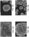
FIGS. 12A to 12D are SEM images showing the composite cathode material of the fifth example of this present disclosure; -
FIGS. 13A to 13D are SEM images showing the composite cathode material of the sixth example of this present disclosure; -
FIG. 14 shows the voltage vs. the charge and discharge capacity curves of the first comparative example, the fourth example, the fifth example and the sixth example of the present disclosure; -
FIG. 15 shows the retention vs. the cycle number curves of the first comparative example, the fourth example, the fifth example and the sixth example of the present disclosure; -
FIG. 16 shows the voltage vs. the charge and discharge capacity curves of the second comparative example, the third comparative example, the first example and the fourth example of the present disclosure; and -
FIG. 17 shows the retention vs. the cycle number curves of the third comparative example, the first example and the fourth example of the present disclosure. - The present disclosure will now be described more specifically with reference to the following embodiments. It is to be noted that the following descriptions of preferred embodiments of this disclosure are presented herein for purpose of illustration and description only. It is not intended to be exhaustive or to be limited to the precise form disclosed. For example, the formation of a first feature over or on a second feature in the description that follows may include embodiments in which the first and second features are formed in direct contact, and may also include embodiments in which additional features may be formed between the first and second features, such that the first and second features may not be in direct contact. In addition, although the "first," "second," "third," and the like terms in the claims be used to describe the various elements can be appreciated, these elements should not be limited by these terms, and these elements are described in the respective embodiments are used to express the different reference numerals, these terms are only used to distinguish one element from another element. For example, a first element could be termed a second element, and, similarly, a second element could be termed a first element, without departing from the scope of example embodiments. Besides, "and / or" and the like may be used herein for including any or all combinations of one or more of the associated listed items. Alternatively, the word "about" means within an acceptable standard error of ordinary skill in the art-recognized average. In addition to the operation / working examples, or unless otherwise specifically stated otherwise, in all cases, all of the numerical ranges, amounts, values and percentages, such as the number for the herein disclosed materials, time duration, temperature, operating conditions, the ratio of the amount, and the like, should be understood as the word "about" decorator. Accordingly, unless otherwise indicated, the numerical parameters of the present invention and scope of the appended patent proposed is to follow changes in the desired approximations. At least, the number of significant digits for each numerical parameter should at least be reported and explained by conventional rounding technique is applied. Herein, it can be expressed as a range between from one endpoint to the other or both endpoints. Unless otherwise specified, all ranges disclosed herein are inclusive.
-
FIG. 1 is a schematic structural view illustrating a composite cathode material according to an embodiment of the present disclosure. In the embodiment, thecomposite cathode material 1 includes acore 10 and acoating layer 20. Thecore 10 is made of the cathode material of lithium nickel manganese oxide (LNMO). Preferably but not exclusively, the lithium nickel manganese oxide (LNMO) is LiNi0.5Mn1.5O4. In the embodiment, thecoating layer 20 is made of the solid electrolyte material of lithium aluminum titanium phosphate (LATP). Preferably but not exclusively, the lithium aluminum titanium phosphate (LATP) is Li1.3Al0.3Ti1.7(PO4)3. In the embodiment, the lithium nickel manganese oxide (LMNO) cathode material is a high-voltage cathode material that does not contain cobalt elements, and has a high redox potential and a high energy density. Preferably but not exclusively, thecomposite cathode material 1 is used in theliquid electrolyte 30, and Li+ ions 11 are allowed in the intercalation/deintercalation with the lithium nickel manganese oxide (LMNO) cathode material in theinner core 10 through thecoating layer 20 of the solid electrolyte. Notably, in the preparation method of the present disclosure, the lithium titanium aluminum phosphate (LATP) is mixed with the pretreatment material through a mechanical mixing way such as a mechanofusion method. Thereafter, the pretreatment material with the LATP mixed is sintered to form the composite cathode material of lithium nickel manganese oxide (LMNO) with the LATP coated thereon. Preferably but not exclusively, the pretreatment material is the nickel-manganese compound material, such as the Ni0.25Mn0.75(OH)2 or Ni0.25Mn0.75O. The lithium nickel manganese oxide (LMNO) cathode material is not directly used for coating process.FIG. 2A is a SEM image showing the nickel-manganese compound material of Ni0.25Mn0.75(OH)2 of the present disclosure.FIG. 2B is a SEM image showing the nickel-manganese compound material of Ni0.25Mn0.75O of the present disclosure.FIG. 2C is a SEM image showing the lithium aluminum titanium phosphate (LATP) of the present disclosure. Certainly, the types, the composition ratio and the material properties of thecore 10 and thecoating layer 20 for thecomposite cathode material 1 are adjustable according to the practical requirements, and are not limited thereto. In the following descriptions, the dry mechanofusion method is used to pretreat the precursor and the solid electrolyte material in the preparation method of thecomposite cathode material 1 of the present disclosure. -
FIG. 3 is a flow chart illustrating a preparation method of the composite cathode material according to a first embodiment of the present disclosure. In the embodiment, a nickel-manganese compound material is provided, as shown in the step S01. Preferably but not exclusively, the nickel-manganese compound material is Ni0.25Mn0.75(OH)2. In the embodiment, the nickel-manganese compound material of Ni0.25Mn0.75(OH)2 has an average particle size ranged from 10 microns to 20 microns. Preferably but not exclusively, the average particle size of the nickel-manganese compound material is 12.90 microns with the surface area of 0.6 m2/g. In addition, a solid electrolyte material of lithium titanium aluminum phosphate (LATP) is provided. The solid electrolyte material has an average particle size ranged from 1 micron to 5 microns. Preferably but not exclusively, the average particle size of the solid electrolyte material is 1.79 microns. In the embodiment, the nickel-manganese compound material of Ni0.25Mn0.75(OH)2 and the LATP solid electrolyte material are mixed in a mechanical mixing to form a composite material, as shown in the step S02. In the embodiment, the LATP solid electrolyte material has a weight percentage relative to the nickel-manganese compound material of Ni0.25Mn0.75(OH)2, and the weight percentage is ranged from 0.2 wt.% to 1.0 wt.%. The mechanical mixing refers to the dry mechanofusion method. In the step S02, the nickel-manganese compound material and the solid electrolyte material are mixed at a rotating speed of 700 rpm for 5 minutes, mixed at a rotating speed of 1400 rpm for 5 minutes, mixed at a rotating speed of 2100 rpm for 5 minutes, mixed at a rotating speed of 2800 rpm for 10 minutes and mixed at a rotating speed of 3500 rpm for 10 minutes in the mechanical mixing. Preferably but not exclusively, the nickel-manganese compound material and the solid electrolyte material are mixed at a working temperature ranged from 25 °C to 45 °C in the mechanical mixing. After the forgoing mechanical mixing is completed, a first heat treatment process is performed, as shown in the step S03. Preferably but not exclusively, the first heat treatment process has a holding temperature ranged from 300°C to 850°C, a treating time ranged from 5 hours to 7 hours, and a temperature rising rate of 2.5°C/min. - Thereafter, in the step S04, a lithium source such as the lithium hydroxide is provided, and the lithium source and the foregoing composite material are mixed and sintered to form the
composite cathode material 1. Preferably but not exclusively, the nickel-manganese compound material of Ni0.25Mn0.75(OH)2 has a molar ratio of 1:1.02 relative to the lithium source in the composite material. In the step S04, the lithium source and the composite material are sintered in a second heat treatment process. Preferably but not exclusively, the second heat treatment process has a holding temperature ranged from 300°C to 710°C, a treating time ranged from 24 hours to 30 hours, and a temperature rising rate of 2.5°C/min. In the embodiment, the obtainedcomposite cathode material 1, as shown inFIG. 1 , includes acore 10 and acoating layer 20. Preferably but not exclusively, thecore 10 is made of LiNi0.5Mn1.5O4, and coated by thecoating layer 20, and thecoating layer 20 is made of the LATP solid electrolyte material. - Notably, in the embodiment, the weight percentage of LATP solid electrolyte material relative to the nickel-manganese compound material of Ni0.25Mn0.75(OH)2 is further controlled and ranged from 0.2 wt.% to 1.0 wt.%. so as to obtain an optimized coating effect of the solid electrolyte material.
-
FIGS. 4A to 4D are SEM images showing the cathode electrode material of the first comparative example. In the first comparative example, the lithium nickel manganese oxide (LMNO) cathode material of LiNi0.5Mn1.5O4) is not coated with the LATP solid electrolyte material. -
FIGS. 5A to 5D are SEM images showing the composite cathode material of the first example of the present disclosure. In the first example, the weight percentage of LATP solid electrolyte material relative to the nickel-manganese compound material of Ni0.25Mn0.75(OH)2 is 0.2 wt.%, and the composite cathode material is obtained through the forgoing steps S01~S04. -
FIGS. 6A to 6D are SEM images showing the composite cathode material of the second example of this present disclosure. In the second example, the weight percentage of LATP solid electrolyte material relative to the nickel-manganese compound material of Ni0.25Mn0.75(OH)2 is 0.5 wt.%, and the composite cathode material is obtained through the forgoing steps S01~S04. -
FIGS. 7A to 7D are SEM images showing the composite cathode material of the third example of this present disclosure. In the third example, the weight percentage of LATP solid electrolyte material relative to the nickel-manganese compound material of Ni0.25Mn0.75(OH)2 is 1.0 wt.%, and the composite cathode material is obtained through the forgoing steps S01~S04. -
FIG. 8 shows the voltage vs. the charge and discharge capacity curves of the first comparative example, the first example, the second example and the third example of the present disclosure. The button batteries made of the first comparative example, the first example, the second example and the third example of the present disclosure are tested at a charge-discharge rate (C-rate) of 0.1C to obtain the results. The positive electrode sheet of the button battery is made of the cathode material, the conductive agent and the binder in a ratio of 94:4:2, and the negative electrode sheet is made of lithium metal. The electrolyte solution of the button battery includes 1.15 M lithium hexafluorophosphate (LiPF6), ethylene carbonate (EC), diethyl carbonate (DEC), ethyl methyl carbonate (EMC) and 5 wt.% fluoroethylene carbonate (FEC). The 0.1C first-cycle and the second-cycle charge and discharge capacity results are listed in Table 1. In addition, Table 1 also lists the rate performance results of the first comparative example, the first example, the second example and the third example of the present disclosure charged at 0.2 and then discharged at 1C/2C/3C/5C. As shown inFIG. 8 and Table 1, the capacities and the rate performance of the first example, the second example and the third example of the present disclosure are all better than those of the first comparative example. It can be seen that the dry mechanical mixing method is used in the present disclosure to mix the nickel-manganese compound material of Ni0.25Mn0.75(OH)2 and the LATP solid electrolyte material in advance. Then, the lithium source is added to mix and sinter with the forgoing composite material to form the composite cathode material with a core and a coating layer. In that, the capacity and the rate performance of the lithium nickel manganese oxide (LMNO) cathode material is improved.Table 1 Samples 0.1C 1st-cycle charge/discharge capacity (mAh/g) 0.1C 2nd-cycle charge/discharge capacity (mAh/g) 1C/2C/3C/5C Discharge capacity (mAh/g) Coulomb efficiency C.E. % First comparative example 150/140 146/140 133/121/110/89 93.3 First example 161/146 156/146 143/135/127/110 90.7 Second example 159/142 150/144 140/132/124/105 89.3 Third example 154/139 148/140 135/126/117/99 90.3 -
FIG. 9 shows the retention vs. the cycle number curves of the first comparative example, the first example, the second example and the third example of the present disclosure. The button batteries made of the first comparative example, the first example, the second example and the third example of the present disclosure are tested at a charge-discharge rate (C-rate) of 1C to obtain the results. As shown inFIG. 9 , the capacity retention rates of the first example, the second example and the third example of the present disclosure are all better than those of the first comparative example. It can be seen that the composite positive electrode material formed by the preparation method of the present disclosure has the advantages of improving the cycle performance and the cycle life of lithium nickel manganese oxide (LMNO) cathode material. -
FIG. 10 is a flow chart illustrating a preparation method of the composite cathode material according to a second embodiment of the present disclosure. In the embodiment, a nickel-manganese compound material is provided, as shown in the step S01'. Preferably but not exclusively, the nickel-manganese compound material is Ni0.25Mn0.75O. In the embodiment, the nickel-manganese compound material of Ni0.25Mn0.75O is made from Ni0.25Mn0.75(OH)2 through a pre-oxidation process. As shown in the step S00', Ni0.25Mn0.75(OH)2 is treated through a pre-oxidation process to obtain the nickel-manganese compound material of Ni0.25Mn0.75O. In the embodiment, the nickel-manganese compound material of Ni0.25Mn0.75O has an average particle size ranged from 10 microns to 20 microns. Preferably but not exclusively, the average particle size of the nickel-manganese compound material is 13.96 microns with the surface area of 20.49 m2/g. Preferably but not exclusively, the pre-oxidation process has a holding temperature ranged from 300°C to 850 °C, a treating time ranged from 5 hours to 7 hours, and a temperature rising rate of 2.5 °C/min. Certainly, in other embodiments, the nickel-manganese compound material of Ni0.25Mn0.75O can be obtained by other processing procedures, and the present disclosure is not limited thereto. Thereafter, as shown in the step S02', a solid electrolyte material of lithium titanium aluminum phosphate (LATP) is provided, the nickel-manganese compound material of Ni0.25Mn0.75O and the LATP solid electrolyte material are mixed in a dry mechanofusion method to form a composite material. In the embodiment, the LATP solid electrolyte material has a weight percentage relative to the nickel-manganese compound material of Ni0.25Mn0.75O, and the weight percentage is ranged from 0.2 wt.% to 1.0 wt.%. Preferably but not exclusively, in the step S02', the nickel-manganese compound material and the solid electrolyte material are mixed at a rotating speed of 700 rpm for 5 minutes, mixed at a rotating speed of 1400 rpm for 5 minutes, mixed at a rotating speed of 2100 rpm for 5 minutes, mixed at a rotating speed of 2800 rpm for 10 minutes and mixed at a rotating speed of 3500 rpm for 10 minutes in the mechanical mixing. Furthermore, the nickel-manganese compound material and the solid electrolyte material are mixed at a working temperature ranged from 25 °C to 45 °C in the mechanical mixing. After the forgoing mechanical mixing is completed, a first heat treatment process is performed, as shown in the step S03'. Preferably but not exclusively, the first heat treatment process has a holding temperature ranged from 300°C to 750°C, a treating time ranged from 5 hours to 7 hours, and a temperature rising rate of 2.5°C/min. - Thereafter, in the step S04', a lithium source such as the lithium hydroxide is provided, and the lithium source and the foregoing composite material are mixed and sintered to form the composite cathode material. Preferably but not exclusively, the forgoing nickel-manganese compound material of Ni0.25Mn0.75O has a molar ratio of 1:1.02 relative to the lithium source in the composite material. In the step S04', the lithium source and the composite material are sintered in a second heat treatment process. Preferably but not exclusively, the second heat treatment process has a holding temperature ranged from 300°C to 710°C, a treating time ranged from 24 hours to 30 hours, and a temperature rising rate of 2.5°C/min. In the embodiment, the obtained
composite cathode material 1, as shown inFIG. 1 , includes acore 10 and acoating layer 20. Preferably but not exclusively, thecore 10 is made of LiNi0.5Mn1.5O4, and coated by thecoating layer 20, and thecoating layer 20 is made of the LATP solid electrolyte material. - Notably, in the embodiment, the weight percentage of LATP solid electrolyte material relative to the nickel-manganese compound material of Ni0.25Mn0.75O is further controlled and ranged from 0.2 wt.% to 1.0 wt.%. so as to obtain an optimized coating effect of the solid electrolyte material.
-
FIGS. 11A to 11D are SEM images showing the composite cathode material of the fourth example of this present disclosure. In the fourth example, the weight percentage of LATP solid electrolyte material relative to the nickel-manganese compound material of Ni0.25Mn0.75O is 0.2 wt.%, and the composite cathode material is obtained through the forgoing steps S01'~S04'. -
FIGS. 12A to 12D are SEM images showing the composite cathode material of the fifth example of this present disclosure. In the fifth example, the weight percentage of LATP solid electrolyte material relative to the nickel-manganese compound material of Ni0.25Mn0.75O is 0.3 wt.%, and the composite cathode material is obtained through the forgoing steps S01'-S04'. -
FIGS. 13A to 13D are SEM images showing the composite cathode material of the sixth example of this present disclosure. In the sixth example, the weight percentage of LATP solid electrolyte material relative to the nickel-manganese compound material of Ni0.25Mn0.75O is 0.5 wt.%, and the composite cathode material is obtained through the forgoing steps S01'~S04'. -
FIG. 14 shows the voltage vs. the charge and discharge capacity curves of the first comparative example, the fourth example, the fifth example and the sixth example of the present disclosure. The button batteries made of the first comparative example, the fourth example, the fifth example and the sixth example of the present disclosure are tested at a charge-discharge rate (C-rate) of 0.1C to obtain the results. The positive electrode sheet of the button battery is made of the cathode material, the conductive agent and the binder in a ratio of 94:4:2, and the negative electrode sheet is made of lithium metal. The electrolyte solution of the button battery includes 1.15 M lithium hexafluorophosphate (LiPF6), ethylene carbonate (EC), diethyl carbonate (DEC), ethyl methyl carbonate (EMC) and 5 wt.% fluoroethylene carbonate (FEC). The 0.1C first-cycle and the second-cycle charge and discharge capacity results are listed in Table 2. In addition, Table 2 also lists the rate performance results of the first comparative example, the fourth example, the fifth example and the sixth example of the present disclosure charged at 0.2 and then discharged at 1C/2C/3C/5C. As shown inFIG. 14 and Table 2, the capacities and the rate performance of the fourth example, the fifth example and the sixth example of the present disclosure are all better than those of the first comparative example. It can be seen that the dry mechanical mixing method is used in the present disclosure to mix the nickel-manganese compound material of Ni0.25Mn0.75O and the LATP solid electrolyte material in advance. Then, the lithium source is added to mix and sinter with the forgoing composite material to form the composite cathode material with a core and a coating layer. In that, the capacity and the rate performance of the lithium nickel manganese oxide (LMNO) cathode material is improved.Table 2 Samples 0.1C 1st-cycle charge/discharge capacity (mAh/g) 0.1C 2nd-cycle charge/discharge capacity (mAh/g) 1C/2C/3C/5C Discharge capacity (mAh/g) Coulomb efficiency C.E. % First comparative example 150/140 146/140 133/121/110/89 93.3 Fourth example 163/146 156/146 140/129/119/97 89.6 Fifth example 160/141 150/142 136/127/118/99 88.1 Sixth example 160/140 152/141 136/128/120/103 87.5 -
FIG. 15 shows the retention vs. the cycle number curves of the first comparative example, the fourth example, the fifth example and the sixth example of the present disclosure. The button batteries made of the first comparative example, the fourth example, the fifth example and the sixth example of the present disclosure are tested at a charge-discharge rate (C-rate) of 1C to obtain the results. As shown inFIG. 15 , the capacity retention rates of the fourth example, the fifth example and the sixth example of the present disclosure are all better than those of the first comparative example. It can be seen that the composite positive electrode material formed by the preparation method of the present disclosure has the advantages of improving the cycle performance and the cycle life of lithium nickel manganese oxide (LMNO) cathode material. - From the above, the weight percentage of the LATP solid electrolyte material relative to the nickel-manganese compound material, such as Ni0.25Mn0.75(OH)2 or Ni0.25Mn0.75O, is controlled and ranged from 0.2 wt.% to 1.0 wt.% in the present disclosure, so that a better coating effect of the composite cathode material is resulted. Preferably, the weight percentage of the LATP solid electrolyte material relative to the nickel-manganese compound material, such as Ni0.25Mn0.75(OH)2 or Ni0.25Mn0.75O, is controlled and ranged from 0.2 wt.% to 0.3 wt.%. That is to say, in the present disclosure, only a small amount of lithium titanium aluminum phosphate (LATP) solid electrolyte is added to form the coating layer to improve the rate performance of the cathode material of lithium nickel manganese oxide (LMNO). The manufacturing cost is further reduced, and an optimized solid-electrolyte coating effect is achieved. On the other hand, it is worth noting that the lithium aluminum titanium phosphate (LATP) is mixed with the pretreatment material of the nickel-manganese compound material in the present disclosure, and then the pretreatment material with the LATP mixed is sintered to form the composite cathode material of lithium nickel manganese oxide (LMNO) with the LATP coated thereon. Preferably, the pretreatment material can be for example the nickel-manganese compound material of Ni0.25Mn0.75(OH)2 or Ni0.25Mn0.75O. The cathode material of lithium nickel manganese oxide (LMNO) material is not directly used for coating process.
- In a second comparative example, 0.2 wt.% LATP solid electrolyte material is added into the lithium nickel manganese oxide (LMNO) cathode material and add. The average particle size of lithium nickel manganese oxide (LMNO) cathode material is about 15.13 microns, with a surface area of 0.31 m2/g. The is directly coated on the surface of the lithium nickel manganese oxide (LMNO) cathode material in the same mixing manner, so as to obtain the second comparative example.
- In a third comparative example, 0.2 wt.% LATP solid electrolyte material is added into the lithium nickel manganese oxide (LMNO) cathode material and add. The average particle size of lithium nickel manganese oxide (LMNO) cathode material is about 15.13 microns, with a surface area of 0.31 m2/g. The LATP solid electrolyte material is directly coated on the surface of the lithium nickel manganese oxide (LMNO) cathode material in the same mixing manner, and a further sintering process is performed, so as to obtain the third comparative example.
-
FIG. 16 shows the voltage vs. the charge and discharge capacity curves of the second comparative example, the third comparative example, the first example and the fourth example of the present disclosure. The button batteries made of the second comparative example, the third comparative example, the first example and the fourth example of the present disclosure are tested at a charge-discharge rate (C-rate) of 0.1C to obtain the results. The 0.1C first-cycle and the second-cycle charge and discharge capacity results are listed in Table 3. In addition, Table 3 also lists the rate performance results of the second comparative example, the third comparative example, the first example and the fourth example of the present disclosure charged at 0.2 and then discharged at 1C/2C/3C/5C. As shown inFIG. 16 and Table 3, the capacities and the rate performance of the first example and the fourth example of the present disclosure are all better than those of the second comparative example and the third comparative example. In the preparation method of the present disclosure, the dry mechanical mixing method is used to mix the nickel-manganese compound material and the LATP solid electrolyte material in advance. Then, the lithium source is added to mix and sinter with the forgoing composite material to form the composite cathode material with a core and a coating layer. It can be seen that the capacity and the rate performance of the composite cathode material prepared through the present disclosure are better than those of the lithium nickel manganese oxide (LMNO) cathode material with the LATP solid electrolyte material directly coated thereon.Table 3 Samples 0.1C 1st-cycle charge/discharge capacity (mAh/g) 0.1C 2nd-cycle charge/discharge capacity (mAh/g) 1C/2C/3C/5C Discharge capacity (mAh/g) Coulomb efficiency C.E. % First example 161/146 156/146 143/135/127/110 90.7 Fourth example 163/146 156/146 140/129/119/97 89.6 Second comparative example 150/135 144/136 132/122/112/91 90.0 Third comparative example 159/143 150/144 139/129/118/94 89.9 -
FIG. 17 shows the retention vs. the cycle number curves of the third comparative example, the first example and the fourth example of the present disclosure. The button batteries made of the third comparative example, the first example and the fourth example of the present disclosure are tested at a charge-discharge rate (C-rate) of 1C to obtain the results. As shown inFIG. 17 , the capacity retention rates of the first example and the fourth example of the present disclosure are all better than those of the third comparative example. The retention after 200th cycles of the first example and the fourth example of the present disclosure is about 10% higher than that of the third comparative example. Different from the third comparative example, the lithium aluminum titanium phosphate (LATP) is mixed with the pretreatment material of the nickel-manganese compound material firstly through a mechanical mixing way such as a mechanofusion method according to the preparation method of the present disclosure. Then, the pretreatment material with the LATP mixed is sintered to form the composite cathode material of lithium nickel manganese oxide (LMNO) with the LATP coated thereon. In this way, the generation of Mn3+ is reduced, and the dissolution of Mn3+ from the positive electrode material and the reduction and deposition on the negative electrode are avoided from resulting in cycle electrical decline. - Notably, the preparation method of the present disclosure uses the dry mechanofusion method to mix the nickel-manganese compound material and the solid electrolyte material, and then performs the heat treatment to produce the LMNO cathode material, so that the solid electrolyte material is coated on the surface of the LMNO cathode material simultaneously when the LMNO cathode material is formed. The process is simple and fast. The performance of the composite cathode material obtained is improved sufficiently and better than that of the LMNO cathode material with the solid electrolyte material directly coated thereon. Furthermore, in order to obtain the optimal coating effect of the solid electrolyte material, only a small amount of LATP solid electrolyte material is added to form the coating layer to improve the rate performance of the LMNO cathode material, and the manufacturing cost is further reduced. By controlling the mixing way of the LATP solid electrolyte and the pretreatment material, the working temperature, the rotating speed and the working time, it allows to avoid the structural defects of the solid electrolyte coating layer caused by high temperature and the excessive friction between particles. At the same time, it ensures that the LMNO cathode material can exert low impedance and good charge and discharge performance through the coating layer of LATP solid electrolyte material.
- Certainly, the compositions of the nickel-manganese compound material of Ni0.25Mn0.75(OH)2 or Ni0.25Mn0.75O, the solid electrolyte material of lithium titanium aluminum phosphate (Li1.3Al0.3Ti1.7(PO4)3, LATP) and the cathode material of lithium nickel manganese oxide (LiNi0.5Mn1.5O4, LMNO) are adjustable according to the practical requirements. Preferably but not exclusively, the nickel-manganese compound material of NixMny(OH)2 or NixMnyO is mixed with the solid electrolyte material of Li1+zAlzTi2-z(PO4)3, x+y=1, and z≦2. Subsequently, the lithium source is added to mix and sinter, and the composite cathode material including the lithium nickel manganese oxide of LiNi2xMn2yO4 with the lithium titanium aluminum phosphate of Li1+zAlzTi2-z(PO4)3 coated on the surface thereof is obtained. It is not redundantly described herein.
- In summary, the present disclosure provides a preparation method of a composite cathode material. By using the dry mechanofusion method to mix the precursor and the solid electrolyte material, the solid electrolyte material is coated on the surface of the cathode material simultaneously when the cathode material is formed. The process is simple and fast, and the performance of the cathode material is improved sufficiently. For the application of lithium nickel manganese oxide (LMNO) cathode material coated the solid electrolyte of lithium titanium aluminum phosphate (Li1.3Al0.3Ti1.7(PO4)3, LATP), the dry mechanical mixing method is used to mix the nickel-manganese compound material, such as Ni0.25Mn0.75(OH)2 or Ni0.25Mn0.75O is mixed with the solid electrolyte material in advance, and then the lithium source is added to mix and sintered to form a composite cathode material with a core and a coating layer. The inner core is made of LiNi0.5Mn1.5O4, and the outer coating layer is made of the solid electrolyte material. Since the solid electrolyte material of lithium aluminum titanium phosphate (LATP) has good ionic conductivity, when the lithium aluminum titanium phosphate (LATP) is coated on the surface of the cathode material of lithium nickel manganese oxide (LMNO) to form a composite cathode material, it facilitates to improve the rate performance and cycle performance of the cathode material of lithium nickel manganese oxide (LMNO), and the coating layer of lithium aluminum titanium phosphate (LATP) can also provide the protection to slow down the impact of the material surface being damaged by the electrolyte solution. Furthermore, in order to obtain the optimal coating effect of the solid electrolyte material, the weight percentage of the solid electrolyte material relative to nickel-manganese compound material, such as Ni0.25Mn0.75(OH)2 or Ni0.25Mn0.75O, is controlled and ranged from 0.2 wt.% to 1.0 wt.%, preferably between 0.2 wt.% and 0.3 wt.%. That is to say, in the present disclosure, only a small amount of lithium titanium aluminum phosphate (LATP) solid electrolyte material is added to form the coating layer to improve the rate performance of the cathode material of lithium nickel manganese oxide (LMNO), and the manufacturing cost is further reduced. Compared with direct coating of the cathode material of lithium nickel manganese oxide (LMNO) with the lithium aluminum titanium phosphate (LATP), the lithium aluminum titanium phosphate (LATP) is mixed with the pretreatment material of the nickel-manganese compound material through a mechanical mixing way such as a mechanofusion method in the present disclosure. Then, the pretreatment material with the LATP mixed is sintered to form the composite cathode material of lithium nickel manganese oxide (LMNO) with the LATP coated thereon. In this way, the generation of Mn3+ is reduced, and the dissolution of Mn3+ from the positive electrode material and the reduction and deposition on the negative electrode are avoided from resulting in cycle electrical decline. The working temperature of the mixing process is ranged for example between 25°C and 45°C, and the mixing processing is performed in stages at a rotating speed ranged from 700 rpm to 3500 rpm for 5 minutes and 30 minutes. By controlling the mixing way of lithium aluminum titanium phosphate (LATP) and the pretreatment material, the working temperature, the rotating speed and the working time, it allows to avoid the structural defects of the solid electrolyte coating layer caused by high temperature and the excessive friction between particles. At the same time, it ensures that the cathode material of lithium nickel manganese oxide (LMNO) can exert low impedance and good charge and discharge performance through the coating layer of LATP solid electrolyte material.
Claims (13)
- A preparation method of a composite cathode material, characterized by comprising steps of:(a) providing a nickel-manganese compound material, wherein the nickel-manganese compound material is NixMny(OH)2 or NixMnyO, x+y=1;(b) providing a solid electrolyte material, and mixing the nickel-manganese compound material and the solid electrolyte material in a mechanical mixing into a composite material, wherein the solid electrolyte material has a weight percentage relative to the nickel-manganese compound material, and the weight percentage is ranged from 0.2 wt.% to 1.0 wt.%; and(c) providing a lithium source, mixing the lithium source and the composite material, and sintering to form the composite cathode material (1), wherein the composite cathode material (1) includes a core (10) and a coating layer (20), the core (10) is made of LiNi2xMn2yO4, and coated by the coating layer (20), and the coating layer (20) is made of the solid electrolyte material.
- The preparation method of the composite cathode material according to claim 1, wherein the nickel-manganese compound material is Ni0.25Mn0.75(OH)2, the step (b) comprises a first heat treatment process after the mechanical mixing, and the first heat treatment process has a holding temperature ranged from 300 °C to 850 °C, a treating time ranged from 5 hours to 7 hours, and a temperature rising rate of 2.5°C/min.
- The preparation method of the composite cathode material according to claim 1, wherein the nickel-manganese compound material is Ni0.25Mn0.75O, the step (a) comprises a pre-oxidation process, and the pre-oxidation process has a holding temperature ranged from 300°C to 850 °C, a treating time ranged from 5 hours to 7 hours, and a temperature rising rate of 2.5 °C/min.
- The preparation method of the composite cathode material according to claim 3, wherein the step (b) comprises a first heat treatment process after the mechanical mixing, and the first heat treatment process has a holding temperature ranged from 300°C to 750°C, a treating time ranged from 5 hours to 7 hours, and a temperature rising rate of 2.5°C/min.
- The preparation method of the composite cathode material according to claim 1, wherein the nickel-manganese compound material and the solid electrolyte material are mixed at a rotating speed of 700 rpm for 5 minutes, mixed at a rotating speed of 1400 rpm for 5 minutes, mixed at a rotating speed of 2100 rpm for 5 minutes, mixed at a rotating speed of 2800 rpm for 10 minutes and mixed at a rotating speed of 3500 rpm for 10 minutes in the mechanical mixing of the step (b).
- The preparation method of the composite cathode material according to claim 1, wherein the nickel-manganese compound material and the solid electrolyte material are mixed at a working temperature ranged from 25 °C to 45 °C in the mechanical mixing of the step (b).
- The preparation method of the composite cathode material according to claim 1, wherein the solid electrolyte material has a chemical formula of Li1+zAlzTi2-z(PO4)3, z≦2.
- The preparation method of the composite cathode material according to claim 1, wherein the mechanical mixing includes a mechanofusion method.
- The preparation method of the composite cathode material according to claim 1, wherein the lithium source and the composite material are mixed at a rotating speed of 700 rpm for 5 minutes, and mixed at a rotating speed of 1400 rpm for 30 minutes in a mechanical manner of the step (c).
- The preparation method of the composite cathode material according to claim 1, wherein the step (c) comprises a second heat treatment process, and the second heat treatment process has a holding temperature ranged from 300°C to 710°C, a treating time ranged from 24 hours to 30 hours, and a temperature rising rate of 2.5°C/min.
- The preparation method of the composite cathode material according to claim 1, wherein the nickel-manganese compound material has a molar ratio of 1:1.02 relative to the lithium source in the composite material in the step (c).
- The preparation method of the composite cathode material according to claim 1, wherein the weight percentage of the solid electrolyte material relative to the nickel-manganese compound material is ranged from 0.2 wt.% to 0.3 wt.%.
- The preparation method of the composite cathode material according to claim 1, wherein the nickel-manganese compound material has an average particle size ranged from 10 microns to 20 microns, and the solid electrolyte material has an average particle size ranged from 1 micron and 5 microns.
Priority Applications (2)
| Application Number | Priority Date | Filing Date | Title |
|---|---|---|---|
| MA69078A MA69078B1 (en) | 2023-05-05 | 2023-09-27 | PROCESS FOR PREPARING A COMPOSITE CATHODE MATERIAL |
| HRP20250869TT HRP20250869T1 (en) | 2023-05-05 | 2023-09-27 | METHOD OF PREPARATION OF COMPOSITE CATHODE MATERIAL |
Applications Claiming Priority (1)
| Application Number | Priority Date | Filing Date | Title |
|---|---|---|---|
| TW112116679A TWI863251B (en) | 2023-05-05 | 2023-05-05 | Preparation method of composite cathode material |
Publications (3)
| Publication Number | Publication Date |
|---|---|
| EP4458775A1 EP4458775A1 (en) | 2024-11-06 |
| EP4458775B1 true EP4458775B1 (en) | 2025-07-02 |
| EP4458775C0 EP4458775C0 (en) | 2025-07-02 |
Family
ID=88207229
Family Applications (1)
| Application Number | Title | Priority Date | Filing Date |
|---|---|---|---|
| EP23200124.8A Active EP4458775B1 (en) | 2023-05-05 | 2023-09-27 | Preparation method of composite cathode material |
Country Status (9)
| Country | Link |
|---|---|
| US (1) | US20240372062A1 (en) |
| EP (1) | EP4458775B1 (en) |
| JP (1) | JP7727694B2 (en) |
| KR (1) | KR102840752B1 (en) |
| AU (1) | AU2023237062B1 (en) |
| ES (1) | ES3037952T3 (en) |
| HR (1) | HRP20250869T1 (en) |
| MA (1) | MA69078B1 (en) |
| TW (1) | TWI863251B (en) |
Family Cites Families (14)
| Publication number | Priority date | Publication date | Assignee | Title |
|---|---|---|---|---|
| EP1786052B1 (en) * | 2004-08-18 | 2012-09-19 | Central Research Institute of Electric Power Industry | Organic electrolyte battery, and process for producing positive electrode sheet for use therein |
| CN100452488C (en) * | 2005-10-28 | 2009-01-14 | 比亚迪股份有限公司 | Preparation method of positive electrode material for ternary composite lithium ion battery |
| US8906553B1 (en) * | 2010-02-26 | 2014-12-09 | Nei Corporation | High voltage cathode material for Li-ion batteries |
| CN102034967A (en) * | 2010-11-09 | 2011-04-27 | 中国海洋石油总公司 | Coprecipitation preparation method of nickel manganese lithium oxide of anode material of high-voltage lithium battery |
| CN102683709A (en) * | 2012-05-22 | 2012-09-19 | 吉首大学 | Surface coverage method for high-voltage nickel manganese acid lithium anode material |
| JP6015591B2 (en) * | 2012-10-26 | 2016-10-26 | トヨタ自動車株式会社 | Non-aqueous electrolyte secondary battery |
| JP7358363B2 (en) * | 2018-09-07 | 2023-10-10 | 株式会社カネカ | Method for manufacturing coated positive electrode active material and lithium ion secondary battery |
| JP7403289B2 (en) * | 2019-11-27 | 2023-12-22 | 太平洋セメント株式会社 | Positive electrode active material composite for lithium ion secondary battery and method for manufacturing the same |
| CN111490243B (en) * | 2020-05-25 | 2022-03-11 | 蜂巢能源科技有限公司 | Composite positive electrode material for lithium ion battery, preparation method and application thereof |
| CN111600014B (en) * | 2020-05-26 | 2022-11-22 | 宁波容百新能源科技股份有限公司 | Modified high-specific-capacity high-nickel ternary cathode material and preparation method thereof |
| CN112635756B (en) * | 2020-12-21 | 2022-09-27 | 国联汽车动力电池研究院有限责任公司 | A kind of high nickel cathode material and its preparation method and application |
| JP7784077B2 (en) * | 2021-07-07 | 2025-12-11 | 三星電子株式会社 | A coated positive electrode active material for a non-aqueous electrolyte secondary battery and a non-aqueous electrolyte secondary battery containing the coated positive electrode active material. |
| CN114388812B (en) * | 2022-03-23 | 2022-06-03 | 宜宾锂宝新材料有限公司 | Nickel-manganese spinel type positive electrode material and preparation method and application thereof |
| CN115084480B (en) * | 2022-07-19 | 2023-09-01 | 成都大学 | A kind of metal oxide-metal sulfide heterojunction material and its preparation method and application |
-
2023
- 2023-05-05 TW TW112116679A patent/TWI863251B/en active
- 2023-06-15 US US18/210,470 patent/US20240372062A1/en active Pending
- 2023-09-26 AU AU2023237062A patent/AU2023237062B1/en active Active
- 2023-09-26 JP JP2023163963A patent/JP7727694B2/en active Active
- 2023-09-27 HR HRP20250869TT patent/HRP20250869T1/en unknown
- 2023-09-27 KR KR1020230130015A patent/KR102840752B1/en active Active
- 2023-09-27 EP EP23200124.8A patent/EP4458775B1/en active Active
- 2023-09-27 ES ES23200124T patent/ES3037952T3/en active Active
- 2023-09-27 MA MA69078A patent/MA69078B1/en unknown
Also Published As
| Publication number | Publication date |
|---|---|
| MA69078B1 (en) | 2025-08-29 |
| TW202445896A (en) | 2024-11-16 |
| EP4458775A1 (en) | 2024-11-06 |
| KR102840752B1 (en) | 2025-07-30 |
| JP2024160916A (en) | 2024-11-15 |
| KR20240161758A (en) | 2024-11-12 |
| TWI863251B (en) | 2024-11-21 |
| ES3037952T3 (en) | 2025-10-08 |
| JP7727694B2 (en) | 2025-08-21 |
| US20240372062A1 (en) | 2024-11-07 |
| HRP20250869T1 (en) | 2025-09-26 |
| AU2023237062B1 (en) | 2024-10-03 |
| EP4458775C0 (en) | 2025-07-02 |
Similar Documents
| Publication | Publication Date | Title |
|---|---|---|
| CN112151798B (en) | Fluoride/oxide co-coated positive electrode material and preparation method thereof | |
| JP7027387B2 (en) | Titanium dope niobate and batteries | |
| KR100889622B1 (en) | Highly stable positive electrode active material for lithium secondary battery, manufacturing method thereof and lithium secondary battery comprising same | |
| EP3288104B1 (en) | Positive electrode active material for non-aqueous electrolyte secondary battery and method for manufacturing same, and non-aqueous electrolyte secondary battery using said positive electrode active material | |
| US20150079471A1 (en) | Lithium-ion battery positive electrode material and preparation method thereof | |
| KR20180063858A (en) | Nickel-based active material precursor for lithium secondary battery, preparing method thereof, nickel-based active material for lithium secondary battery formed thereof, and lithium secondary battery comprising positive electrode including the nickel-based active material | |
| EP2763220A2 (en) | Precursor of cathode active material for a lithium secondary battery, method for manufacturing the precursor, cathode active material, and lithium secondary battery including the cathode active material | |
| CN110226251A (en) | Nickel hydroxide active material presoma and preparation method thereof, nickel hydroxide active material and lithium secondary battery | |
| KR20210007808A (en) | Positive active material for lithium secondary battery, preparing method thereof, and lithium secondary battery comprising positive electrode including positive active material | |
| JP2011096626A (en) | Positive electrode active material, method of manufacturing the positive electrode active material, and nonaqueous electrolyte secondary battery using positive electrode active material | |
| EP4033565B1 (en) | Positive electrode active material for lithium ion secondary battery, and lithium ion secondary battery | |
| KR20180065944A (en) | Nickel-based active material for lithium secondary battery, preparing method thereof, and lithium secondary battery including a positive electrode including the same | |
| CN118658993A (en) | Positive electrode material and preparation method and application thereof | |
| EP3486220B2 (en) | Cathode active material for lithium secondary battery and lithium secondary battery including the same | |
| EP4458775B1 (en) | Preparation method of composite cathode material | |
| EP4475220A1 (en) | Positive electrode composite material and preparation method therefor, positive electrode sheet, and battery | |
| CN117317209A (en) | Positive electrode material and preparation method thereof | |
| KR20180094567A (en) | Positive active material for lithium secondary battery | |
| TWI832549B (en) | Core-shell particle and lithium ion battery | |
| CN118899408A (en) | Preparation method of composite positive electrode material | |
| EP3489198A1 (en) | Cathode active material of lithium secondary battery | |
| KR102946408B1 (en) | positive electrode active material for sodium secondary battery, method for preparing the same and sodium secondary battery including the same | |
| KR102865464B1 (en) | All-solid rechargeable batteries | |
| CN118800899B (en) | Ternary material, preparation method and application thereof, and battery | |
| KR20250079335A (en) | Manufacturing method of artificial solid ekectrolyte interface film for lithium secondary battery |
Legal Events
| Date | Code | Title | Description |
|---|---|---|---|
| REG | Reference to a national code |
Ref country code: HR Ref legal event code: TUEP Ref document number: P20250869T Country of ref document: HR |
|
| PUAI | Public reference made under article 153(3) epc to a published international application that has entered the european phase |
Free format text: ORIGINAL CODE: 0009012 |
|
| STAA | Information on the status of an ep patent application or granted ep patent |
Free format text: STATUS: REQUEST FOR EXAMINATION WAS MADE |
|
| 17P | Request for examination filed |
Effective date: 20240508 |
|
| AK | Designated contracting states |
Kind code of ref document: A1 Designated state(s): AL AT BE BG CH CY CZ DE DK EE ES FI FR GB GR HR HU IE IS IT LI LT LU LV MC ME MK MT NL NO PL PT RO RS SE SI SK SM TR |
|
| RAV | Requested validation state of the european patent: fee paid |
Extension state: MA Effective date: 20241213 |
|
| REG | Reference to a national code |
Ref country code: DE Ref legal event code: R079 Free format text: PREVIOUS MAIN CLASS: C01G0053000000 Ipc: C01G0053540000 Ref document number: 602023004487 Country of ref document: DE |
|
| GRAP | Despatch of communication of intention to grant a patent |
Free format text: ORIGINAL CODE: EPIDOSNIGR1 |
|
| STAA | Information on the status of an ep patent application or granted ep patent |
Free format text: STATUS: GRANT OF PATENT IS INTENDED |
|
| RIC1 | Information provided on ipc code assigned before grant |
Ipc: H01M 10/052 20100101ALI20250317BHEP Ipc: H01M 4/62 20060101ALI20250317BHEP Ipc: H01M 10/0562 20100101ALI20250317BHEP Ipc: H01M 4/525 20100101ALI20250317BHEP Ipc: H01M 4/505 20100101ALI20250317BHEP Ipc: H01M 4/36 20060101ALI20250317BHEP Ipc: C01G 53/54 20250101AFI20250317BHEP |
|
| INTG | Intention to grant announced |
Effective date: 20250415 |
|
| GRAS | Grant fee paid |
Free format text: ORIGINAL CODE: EPIDOSNIGR3 |
|
| GRAA | (expected) grant |
Free format text: ORIGINAL CODE: 0009210 |
|
| STAA | Information on the status of an ep patent application or granted ep patent |
Free format text: STATUS: THE PATENT HAS BEEN GRANTED |
|
| AK | Designated contracting states |
Kind code of ref document: B1 Designated state(s): AL AT BE BG CH CY CZ DE DK EE ES FI FR GB GR HR HU IE IS IT LI LT LU LV MC ME MK MT NL NO PL PT RO RS SE SI SK SM TR |
|
| REG | Reference to a national code |
Ref country code: GB Ref legal event code: FG4D |
|
| REG | Reference to a national code |
Ref country code: CH Ref legal event code: EP |
|
| REG | Reference to a national code |
Ref country code: DE Ref legal event code: R096 Ref document number: 602023004487 Country of ref document: DE |
|
| REG | Reference to a national code |
Ref country code: IE Ref legal event code: FG4D |
|
| REG | Reference to a national code |
Ref country code: MA Ref legal event code: VAGR Ref document number: 69078 Country of ref document: MA Kind code of ref document: B1 |
|
| U01 | Request for unitary effect filed |
Effective date: 20250729 |
|
| U07 | Unitary effect registered |
Designated state(s): AT BE BG DE DK EE FI FR IT LT LU LV MT NL PT RO SE SI Effective date: 20250804 |
|
| REG | Reference to a national code |
Ref country code: HR Ref legal event code: T1PR Ref document number: P20250869 Country of ref document: HR |
|
| REG | Reference to a national code |
Ref country code: ES Ref legal event code: FG2A Ref document number: 3037952 Country of ref document: ES Kind code of ref document: T3 Effective date: 20251008 |
|
| REG | Reference to a national code |
Ref country code: HR Ref legal event code: ODRP Ref document number: P20250869 Country of ref document: HR Payment date: 20250916 Year of fee payment: 3 |
|
| PGFP | Annual fee paid to national office [announced via postgrant information from national office to epo] |
Ref country code: NO Payment date: 20250925 Year of fee payment: 3 |
|
| PGFP | Annual fee paid to national office [announced via postgrant information from national office to epo] |
Ref country code: TR Payment date: 20250925 Year of fee payment: 3 |
|
| PGFP | Annual fee paid to national office [announced via postgrant information from national office to epo] |
Ref country code: HR Payment date: 20250916 Year of fee payment: 3 |
|
| U20 | Renewal fee for the european patent with unitary effect paid |
Year of fee payment: 3 Effective date: 20250930 |
|
| VSFP | Annual fee paid to validation state [announced via postgrant information from national office to epo] |
Ref country code: MA Payment date: 20251008 Year of fee payment: 3 |
|
| PG25 | Lapsed in a contracting state [announced via postgrant information from national office to epo] |
Ref country code: IS Free format text: LAPSE BECAUSE OF FAILURE TO SUBMIT A TRANSLATION OF THE DESCRIPTION OR TO PAY THE FEE WITHIN THE PRESCRIBED TIME-LIMIT Effective date: 20251102 |
|
| PG25 | Lapsed in a contracting state [announced via postgrant information from national office to epo] |
Ref country code: GR Free format text: LAPSE BECAUSE OF FAILURE TO SUBMIT A TRANSLATION OF THE DESCRIPTION OR TO PAY THE FEE WITHIN THE PRESCRIBED TIME-LIMIT Effective date: 20251003 |
|
| PG25 | Lapsed in a contracting state [announced via postgrant information from national office to epo] |
Ref country code: CZ Free format text: LAPSE BECAUSE OF FAILURE TO SUBMIT A TRANSLATION OF THE DESCRIPTION OR TO PAY THE FEE WITHIN THE PRESCRIBED TIME-LIMIT Effective date: 20250702 |
|
| PG25 | Lapsed in a contracting state [announced via postgrant information from national office to epo] |
Ref country code: PL Free format text: LAPSE BECAUSE OF FAILURE TO SUBMIT A TRANSLATION OF THE DESCRIPTION OR TO PAY THE FEE WITHIN THE PRESCRIBED TIME-LIMIT Effective date: 20250702 |
|
| PG25 | Lapsed in a contracting state [announced via postgrant information from national office to epo] |
Ref country code: RS Free format text: LAPSE BECAUSE OF FAILURE TO SUBMIT A TRANSLATION OF THE DESCRIPTION OR TO PAY THE FEE WITHIN THE PRESCRIBED TIME-LIMIT Effective date: 20251002 |
|
| PGFP | Annual fee paid to national office [announced via postgrant information from national office to epo] |
Ref country code: ES Payment date: 20251020 Year of fee payment: 3 |
|
| PG25 | Lapsed in a contracting state [announced via postgrant information from national office to epo] |
Ref country code: SM Free format text: LAPSE BECAUSE OF FAILURE TO SUBMIT A TRANSLATION OF THE DESCRIPTION OR TO PAY THE FEE WITHIN THE PRESCRIBED TIME-LIMIT Effective date: 20250702 |
|
| PG25 | Lapsed in a contracting state [announced via postgrant information from national office to epo] |
Ref country code: SK Free format text: LAPSE BECAUSE OF FAILURE TO SUBMIT A TRANSLATION OF THE DESCRIPTION OR TO PAY THE FEE WITHIN THE PRESCRIBED TIME-LIMIT Effective date: 20250702 |