EP4458757A1 - Carbon dioxide gas supply device - Google Patents
Carbon dioxide gas supply device Download PDFInfo
- Publication number
- EP4458757A1 EP4458757A1 EP22915514.8A EP22915514A EP4458757A1 EP 4458757 A1 EP4458757 A1 EP 4458757A1 EP 22915514 A EP22915514 A EP 22915514A EP 4458757 A1 EP4458757 A1 EP 4458757A1
- Authority
- EP
- European Patent Office
- Prior art keywords
- carbon dioxide
- pressure
- dioxide gas
- channel
- valve
- Prior art date
- Legal status (The legal status is an assumption and is not a legal conclusion. Google has not performed a legal analysis and makes no representation as to the accuracy of the status listed.)
- Withdrawn
Links
Images


Classifications
-
- B—PERFORMING OPERATIONS; TRANSPORTING
- B67—OPENING, CLOSING OR CLEANING BOTTLES, JARS OR SIMILAR CONTAINERS; LIQUID HANDLING
- B67D—DISPENSING, DELIVERING OR TRANSFERRING LIQUIDS, NOT OTHERWISE PROVIDED FOR
- B67D1/00—Apparatus or devices for dispensing beverages on draught
- B67D1/04—Apparatus utilising compressed air or other gas acting directly or indirectly on beverages in storage containers
-
- B—PERFORMING OPERATIONS; TRANSPORTING
- B67—OPENING, CLOSING OR CLEANING BOTTLES, JARS OR SIMILAR CONTAINERS; LIQUID HANDLING
- B67D—DISPENSING, DELIVERING OR TRANSFERRING LIQUIDS, NOT OTHERWISE PROVIDED FOR
- B67D1/00—Apparatus or devices for dispensing beverages on draught
- B67D1/08—Details
- B67D1/0878—Safety, warning or controlling devices
- B67D1/0882—Devices for controlling the dispensing conditions
- B67D1/0884—Means for controlling the parameters of the state of the liquid to be dispensed, e.g. temperature, pressure
-
- B—PERFORMING OPERATIONS; TRANSPORTING
- B67—OPENING, CLOSING OR CLEANING BOTTLES, JARS OR SIMILAR CONTAINERS; LIQUID HANDLING
- B67D—DISPENSING, DELIVERING OR TRANSFERRING LIQUIDS, NOT OTHERWISE PROVIDED FOR
- B67D1/00—Apparatus or devices for dispensing beverages on draught
- B67D1/08—Details
- B67D1/12—Flow or pressure control devices or systems, e.g. valves, gas pressure control, level control in storage containers
-
- B—PERFORMING OPERATIONS; TRANSPORTING
- B67—OPENING, CLOSING OR CLEANING BOTTLES, JARS OR SIMILAR CONTAINERS; LIQUID HANDLING
- B67D—DISPENSING, DELIVERING OR TRANSFERRING LIQUIDS, NOT OTHERWISE PROVIDED FOR
- B67D1/00—Apparatus or devices for dispensing beverages on draught
- B67D1/08—Details
- B67D1/12—Flow or pressure control devices or systems, e.g. valves, gas pressure control, level control in storage containers
- B67D1/125—Safety means, e.g. over-pressure valves
-
- B—PERFORMING OPERATIONS; TRANSPORTING
- B67—OPENING, CLOSING OR CLEANING BOTTLES, JARS OR SIMILAR CONTAINERS; LIQUID HANDLING
- B67D—DISPENSING, DELIVERING OR TRANSFERRING LIQUIDS, NOT OTHERWISE PROVIDED FOR
- B67D1/00—Apparatus or devices for dispensing beverages on draught
- B67D1/08—Details
- B67D1/12—Flow or pressure control devices or systems, e.g. valves, gas pressure control, level control in storage containers
- B67D1/1252—Gas pressure control means, e.g. for maintaining proper carbonation
-
- G—PHYSICS
- G05—CONTROLLING; REGULATING
- G05D—SYSTEMS FOR CONTROLLING OR REGULATING NON-ELECTRIC VARIABLES
- G05D16/00—Control of fluid pressure
- G05D16/04—Control of fluid pressure without auxiliary power
- G05D16/06—Control of fluid pressure without auxiliary power the sensing element being a flexible membrane, yielding to pressure, e.g. diaphragm, bellows, capsule
-
- G—PHYSICS
- G05—CONTROLLING; REGULATING
- G05D—SYSTEMS FOR CONTROLLING OR REGULATING NON-ELECTRIC VARIABLES
- G05D16/00—Control of fluid pressure
- G05D16/20—Control of fluid pressure characterised by the use of electric means
Definitions
- the present invention relates to a carbon dioxide gas supply apparatus.
- PTL 1 discloses a mechanical pressure adjuster that supplies a carbon dioxide gas to a beer barrel.
- this pressure adjuster the temperature of beer that passes from a beer barrel through a beer passage via a dispenser is sensed by a thermo-wax pellet, and a plunger is expanded/contracted, thereby opening/closing a valve and thus automatically adjusting the pressure of the carbon dioxide gas in accordance with the beer temperature.
- the mechanical pressure adjuster there is room for improvement concerning a delay of follow-up to a temperature change.
- PTL 2 discloses an electric control type carbon dioxide gas adjuster configured to control a pressurizing valve and a pressure reducing valve based on the output of a temperature sensor that measures the temperature of a sparkling beverage.
- the present invention has as its object to provide a carbon dioxide gas supply apparatus having a configuration advantageous in preventing a pressure adjuster from sticking due to a beverage component.
- One aspect of the present invention is directed to a carbon dioxide gas supply apparatus, and the carbon dioxide gas supply apparatus comprises a pressure adjuster including a primary-side port and a secondary-side port and configured to adjust a pressure of a carbon dioxide gas supplied from a carbon dioxide gas supply source to the primary-side port and send the carbon dioxide gas from the secondary-side port; a relief valve connected to a first channel configured to connect the secondary-side port and a beverage barrel; and a controller configured to control the pressure adjuster and the relief valve, wherein the controller controls the relief valve such that a pressure in the first channel is reduced in accordance with an output of a temperature sensor configured to detect a temperature of a beverage sent from the beverage barrel to a beverage server.
- a pressure adjuster including a primary-side port and a secondary-side port and configured to adjust a pressure of a carbon dioxide gas supplied from a carbon dioxide gas supply source to the primary-side port and send the carbon dioxide gas from the secondary-side port
- a relief valve connected to a first channel configured to connect the secondary
- a carbon dioxide gas supply apparatus having a configuration advantageous in preventing a pressure adjuster from sticking due to a beverage component.
- Fig. 1 schematically shows the configuration of a carbon dioxide gas supply apparatus 100 according to the embodiment.
- the carbon dioxide gas supply apparatus 100 is configured to adjust a carbon dioxide gas supplied from a carbon dioxide gas supply source (for example, a carbon dioxide gas cylinder) 3 to a target pressure and supply it to a beverage barrel 1.
- the carbon dioxide gas supply apparatus 100 can also be understood as a beverage pouring system.
- the carbon dioxide gas supplied to the beverage barrel 1 pushes down the liquid surface of a sparkling beverage in the beverage barrel 1 by its pressure, and the sparkling beverage in the beverage barrel 1 is thus pushed out from the beverage barrel 1 and supplied to a beverage server 2.
- the sparkling beverage can be, for example, beer, low-malt beer, a beer-like beverage, sour, highball, or the like.
- the carbon dioxide gas supply apparatus 100 includes a pressure adjuster 10, a relief valve 20, and a controller 30.
- the pressure adjuster 10 can include a primary-side port P1 and a secondary-side port P2.
- the pressure adjuster 10 can be configured to adjust the pressure of the carbon dioxide gas supplied from the carbon dioxide gas supply source 3 to the primary-side port P1 and send it from the secondary-side port P2.
- the secondary-side port P2 of the pressure adjuster 10 is connected to the beverage barrel 1 via a first channel PH1.
- the relief valve 20 can be connected to the first channel PH1.
- the controller 30 can be configured to control the pressure adjuster 10 and the relief valve 20. Based on the output of a temperature sensor 81 that detects the temperature of the sparkling beverage sent from the beverage barrel 1 to the beverage server 2, the controller 30 can control the relief valve 20 such that the pressure in the first channel PH1 is reduced (or the first channel PH1 is temporarily opened to the atmosphere). Control of the relief valve 20 by the controller 30 may be performed by the controller 30 supplying an electrical signal to the relief valve 20, or may be performed indirectly by the controller 30 controlling another constituent element (for example, a three-way valve V4), as will be described later. Such other constituent element may be regarded as a constituent element of the relief valve 20.
- the temperature sensor 81 can be arranged in or connected to a channel that connects the beverage barrel 1 and the beverage server 2.
- the temperature sensor 81 may be understood as a constituent element of the carbon dioxide gas supply apparatus 100 or, or may be understood not as a constituent element of the carbon dioxide gas supply apparatus 100.
- the temperature sensor 81 may be provided in the beverage server 2. Alternatively, the temperature sensor 81 may be attached to the beverage barrel 1.
- the carbon dioxide gas supply apparatus 100 can further include a second channel PH2 that supplies the carbon dioxide gas supplied from the carbon dioxide gas supply source 3 to the relief valve 20 to supply, to the relief valve 20, a force for maintaining the relief valve 20 in a closed state.
- the carbon dioxide gas supply apparatus 100 can further include a regulator 40 that reduces the pressure of the carbon dioxide gas supplied from the carbon dioxide gas supply source 3 to a predetermined pressure.
- the carbon dioxide gas supply apparatus 100 can further include a third channel PH3 that supplies, to the pressure adjuster 10, the carbon dioxide gas whose pressure is reduced to the predetermined pressure by the regulator 40.
- the second channel PH2 can be arranged to supply, to the relief valve 20, the carbon dioxide gas whose pressure is reduced to the predetermined pressure by the regulator 40.
- the configuration of the relief valve 20 is not limited to a specific configuration.
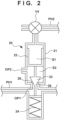
- Fig. 2 is an enlarged view of the relief valve 20 in the example shown in Fig. 1 .
- the relief valve 20 can include a cylinder 21, a piston 22, a valve body 23, and a spring 24.
- the cylinder 21 can include, for example, a first opening OP1 provided with a seat 29, and a second opening OP2 communicating with the atmosphere.
- the piston 22 can separate the internal space of the cylinder 21 to a first space S1 and a second space S2.
- the valve body 23 can be arranged in the second space S2 and supported by the piston 22 to face the seat 29.
- the spring 24 can be arranged to press the valve body 23 to form a gap 28 between the seat 29 and the valve body 23.
- the carbon dioxide gas supplied to the first space S1 via the second channel PH2 is introduced into the first space S1 and can give a force in a direction of pressing the valve body 23 against the seat 29 to the piston 22.
- the first opening OP1 communicates with the first channel PH1.
- the second opening OP2 makes the second space S2 communicate with the atmosphere.
- the carbon dioxide gas supply apparatus 100 can further include the three-way valve V4 arranged in the second channel PH2.
- the three-way valve V4 can be controlled by the controller 30 to a first state in which the second channel PH2 and the first space S 1 of the relief valve 20 are connected or a second state in which the first space S1 of the relief valve 20 communicates with the atmosphere.
- the carbon dioxide gas supply apparatus 100 can further include a check valve 60 arranged in the second channel PH2 to supply the carbon dioxide gas from the regulator 40 to the three-way valve V4.
- the check valve 60 can function to prevent the pressure of the carbon dioxide gas to be supplied to the three-way valve V4 or the first space S1 of the relief valve 20 from lowering when the pressure of the carbon dioxide gas supplied from the carbon dioxide gas supply source 3 lowers due to the decrease of the amount of the carbon dioxide gas in the carbon dioxide gas supply source 3.
- the carbon dioxide gas supply apparatus 100 can further include a safety valve V3 connected to a position between the pressure adjuster 10 and the connecting portion of the relief valve 20 in the first channel PH1.
- the safety valve V3 functions to prevent the pressure in the first channel PH1 from being a predetermined pressure or more.
- the configuration of the pressure adjuster 10 is not limited to a specific configuration.
- the pressure adjuster 10 can include a pressure intensifying valve V1 configured to increase the pressure in the first channel PH1, and a pressure reducing valve V2 configured to reduce the pressure in the first channel PH1.
- the internal space of the pressure adjuster 10 can include a first space S3, a second space S4, and a third space S5.
- the first space S3 and the second space S4 are partitioned by a diaphragm 13.
- a spring 14 can be connected to the diaphragm 13.
- a valve body 11 can be coupled with the diaphragm 13, and a spring 12 can be connected to the valve body 11.
- the position of the valve body 11 is decided by the restoring force of the springs 12 and 14 and the diaphragm 13 and the pressure difference between the first space S3 and the second space S4, and the gap between the valve body 11 and the seat facing this is thus decided.
- the pressure intensifying valve V1 is opened, the carbon dioxide gas is introduced from the third channel PH3 to the first space S3 via the third space S5, and the pressure in the first space S3 increases.
- the carbon dioxide gas passing through a valve formed by the valve body 11 and a seal facing this increases, and the pressure of the carbon dioxide gas in the second space S4 increases.
- the pressure in the first space S3 increases until the restoring force of the springs 12 and 14 and the diaphragm 13 and the pressure difference between the first space S3 and the second space S4 balance, and the pressure in the second space S4, that is, the first channel PH1 also increases.
- the pressure reducing valve V2 If the pressure reducing valve V2 is opened, the carbon dioxide gas is discharged to the first space S3, and the pressure in the first space S3 decreases.
- the carbon dioxide gas passing through the valve formed by the valve body 11 and the seal facing this decreases, and the pressure of the carbon dioxide gas in the second space S4 decreases.
- the pressure in the first space S3 decreases until the restoring force of the springs 12 and 14 and the diaphragm 13 and the pressure difference between the first space S3 and the second space S4 balance, and the pressure in the second space S4, that is, the first channel PH1 also decreases.
- the controller 30 can be configured to, when reducing the pressure in the first channel PH1 to reduce the pressure in the beverage barrel 1, open the relief valve 20 in accordance with a target pressure, that is, make the first channel PH1 communicate with the atmosphere via the second opening OP2 in a state in which the pressure reducing valve V2 is closed.
- a target pressure that is, make the first channel PH1 communicate with the atmosphere via the second opening OP2 in a state in which the pressure reducing valve V2 is closed.
- the carbon dioxide gas supply apparatus 100 can also include a pressure sensor 82 that detects the pressure in the first channel PH1.
- the controller 30 can control the pressure intensifying valve V1, the pressure reducing valve V2, and the relief valve 20 based on the output of the pressure sensor 82. Note that in an example, the controller 30 controls the three-way valve V4, thereby controlling the relief valve 20.
- the carbon dioxide gas supply apparatus 100 may further include a pressure sensor 83 that detects the pressure in the third channel PH3. The controller 30 can detect shortage of the carbon dioxide gas in the carbon dioxide gas supply source 3 based on the output of the pressure sensor 83.
- the pressure intensifying valve V1, the pressure reducing valve V2, and the three-way valve V4, and the temperature sensor 81, the pressure sensor 82, and the pressure sensor 83 are not connected to the controller 30 in Fig. 1 , but these are connected to the controller 30 by wire or wirelessly.
- Fig. 3 schematically shows the operation of the carbon dioxide gas supply apparatus 100.
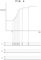
- Fig. 4 is an enlarged view of a portion A in Fig. 3
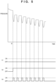
- Fig. 5 is an enlarged view of a portion B in Fig. 3 .
- the ordinate represents the pressure detected by the pressure sensor 82.
- the pressure may be the output value itself of the pressure sensor 82, or may be a value obtained by converting the output value (for example, an analog value or digital value represented by a relative measure) into a value of another measure (typically, a temperature).
- the abscissa represents time.
- the example shown in Fig. 3 starts from a point of time when the beverage barrel 1 is brought from the outside (for example, 35°C) into a room (for example, 25°C), the first channel PH1 is connected to the beverage barrel 1, and the beverage server 2 is also connected.
- the pressure in the first channel PH1 increases.
- the beverage server 2 is operated to pour the beverage.
- the pressure in the beverage barrel 1 and the first channel PH1 thus lowers a little.
- the temperature indicated by the output of the temperature sensor 81 rises.
- the controller 30 changes the target pressure in the beverage barrel 1 (and the first channel PH1) to a pressure according to the temperature.
- the controller 30 controls the pressure intensifying valve V1, the pressure reducing valve V2, and the relief valve 20 (the pressure intensifying valve V1, the pressure reducing valve V2, and the three-way valve V4) based on the target pressure after the change. More specifically, in this example, the controller 30 can control the pressure intensifying valve V1, the pressure reducing valve V2, and the three-way valve V4 such that the temperature indicated by the output of the pressure sensor 82 matches the target pressure.
- the controller 30 can intermittently open the pressure intensifying valve V1, as exemplarily shown in Fig. 4 .
- the beverage server 2 is further operated to pour the sparkling beverage
- the beverage server 2 is further operated to pour the sparkling beverage.
- the beverage server 2 is further operated to pour the beverage.
- the temperature indicated by the output of the temperature sensor 81 lowers.
- the controller 30 changes the target pressure in the beverage barrel 1 (and the first channel PH1) to a pressure according to the temperature.
- the controller 30 controls the pressure intensifying valve V1, the pressure reducing valve V2, and the relief valve 20 (the pressure intensifying valve V1, the pressure reducing valve V2, and the three-way valve V4) based on the target pressure after the change. More specifically, in this example, the controller 30 can control the pressure intensifying valve V1, the pressure reducing valve V2, and the three-way valve V4 such that the temperature indicated by the output of the pressure sensor 82 matches the target pressure.
- the controller 30 can intermittently open the three-way valve V4 in a state in which the pressure reducing valve V2 is continuously opened, as exemplarily shown in Fig. 5 .
Landscapes
- Physics & Mathematics (AREA)
- Fluid Mechanics (AREA)
- General Physics & Mathematics (AREA)
- Engineering & Computer Science (AREA)
- Automation & Control Theory (AREA)
- Devices For Dispensing Beverages (AREA)
- Control Of Fluid Pressure (AREA)
Abstract
Description
- The present invention relates to a carbon dioxide gas supply apparatus.
-
PTL 1 discloses a mechanical pressure adjuster that supplies a carbon dioxide gas to a beer barrel. In this pressure adjuster, the temperature of beer that passes from a beer barrel through a beer passage via a dispenser is sensed by a thermo-wax pellet, and a plunger is expanded/contracted, thereby opening/closing a valve and thus automatically adjusting the pressure of the carbon dioxide gas in accordance with the beer temperature. In the mechanical pressure adjuster, there is room for improvement concerning a delay of follow-up to a temperature change.PTL 2 discloses an electric control type carbon dioxide gas adjuster configured to control a pressurizing valve and a pressure reducing valve based on the output of a temperature sensor that measures the temperature of a sparkling beverage. - However, in the electric carbon dioxide gas adjuster as described in
PTL 2, when lowering the pressure in the beer barrel, a carbon dioxide gas containing a beer mist (beverage component) is discharged from the beer barrel via the pressure reducing valve of the carbon dioxide gas adjuster. Due to such a beer mist, movable portions of the pressure reducing valve may stick. -
- PTL 1:
Japanese Patent Laid-Open No. 2006-143265 - PTL 2:
Japanese Patent Laid-Open No. 2009-280223 - The present invention has as its object to provide a carbon dioxide gas supply apparatus having a configuration advantageous in preventing a pressure adjuster from sticking due to a beverage component.
- One aspect of the present invention is directed to a carbon dioxide gas supply apparatus, and the carbon dioxide gas supply apparatus comprises a pressure adjuster including a primary-side port and a secondary-side port and configured to adjust a pressure of a carbon dioxide gas supplied from a carbon dioxide gas supply source to the primary-side port and send the carbon dioxide gas from the secondary-side port; a relief valve connected to a first channel configured to connect the secondary-side port and a beverage barrel; and a controller configured to control the pressure adjuster and the relief valve, wherein the controller controls the relief valve such that a pressure in the first channel is reduced in accordance with an output of a temperature sensor configured to detect a temperature of a beverage sent from the beverage barrel to a beverage server.
- According to the present invention, there is provided a carbon dioxide gas supply apparatus having a configuration advantageous in preventing a pressure adjuster from sticking due to a beverage component.
-
-
Fig. 1 is a view schematically showing the configuration of a carbon dioxide gas supply apparatus according to the embodiment; -
Fig. 2 is an enlarged view of a relief valve in an example shown inFig. 1 ; -
Fig. 3 is a view schematically showing the operation of the carbon dioxide gas supply apparatus according to the embodiment; -
Fig. 4 is an enlarged view of a portion A inFig. 3 ; and -
Fig. 5 is an enlarged view of a portion B inFig. 3 . - Hereinafter, embodiments will be described in detail with reference to the attached drawings. Note, the following embodiments are not intended to limit the scope of the claimed invention, and limitation is not made to an invention that requires a combination of all features described in the embodiments. Two or more of the multiple features described in the embodiments may be combined as appropriate. Furthermore, the same reference numerals are given to the same or similar configurations, and redundant description thereof is omitted.
-
Fig. 1 schematically shows the configuration of a carbon dioxidegas supply apparatus 100 according to the embodiment. The carbon dioxidegas supply apparatus 100 is configured to adjust a carbon dioxide gas supplied from a carbon dioxide gas supply source (for example, a carbon dioxide gas cylinder) 3 to a target pressure and supply it to abeverage barrel 1. The carbon dioxidegas supply apparatus 100 can also be understood as a beverage pouring system. The carbon dioxide gas supplied to thebeverage barrel 1 pushes down the liquid surface of a sparkling beverage in thebeverage barrel 1 by its pressure, and the sparkling beverage in thebeverage barrel 1 is thus pushed out from thebeverage barrel 1 and supplied to abeverage server 2. The sparkling beverage can be, for example, beer, low-malt beer, a beer-like beverage, sour, highball, or the like. - The carbon dioxide
gas supply apparatus 100 includes apressure adjuster 10, arelief valve 20, and acontroller 30. Thepressure adjuster 10 can include a primary-side port P1 and a secondary-side port P2. Thepressure adjuster 10 can be configured to adjust the pressure of the carbon dioxide gas supplied from the carbon dioxide gas supply source 3 to the primary-side port P1 and send it from the secondary-side port P2. The secondary-side port P2 of thepressure adjuster 10 is connected to thebeverage barrel 1 via a first channel PH1. Therelief valve 20 can be connected to the first channel PH1. - The
controller 30 can be configured to control thepressure adjuster 10 and therelief valve 20. Based on the output of atemperature sensor 81 that detects the temperature of the sparkling beverage sent from thebeverage barrel 1 to thebeverage server 2, thecontroller 30 can control therelief valve 20 such that the pressure in the first channel PH1 is reduced (or the first channel PH1 is temporarily opened to the atmosphere). Control of therelief valve 20 by thecontroller 30 may be performed by thecontroller 30 supplying an electrical signal to therelief valve 20, or may be performed indirectly by thecontroller 30 controlling another constituent element (for example, a three-way valve V4), as will be described later. Such other constituent element may be regarded as a constituent element of therelief valve 20. - The
temperature sensor 81 can be arranged in or connected to a channel that connects thebeverage barrel 1 and thebeverage server 2. Thetemperature sensor 81 may be understood as a constituent element of the carbon dioxidegas supply apparatus 100 or, or may be understood not as a constituent element of the carbon dioxidegas supply apparatus 100. Thetemperature sensor 81 may be provided in thebeverage server 2. Alternatively, thetemperature sensor 81 may be attached to thebeverage barrel 1. - The carbon dioxide
gas supply apparatus 100 can further include a second channel PH2 that supplies the carbon dioxide gas supplied from the carbon dioxide gas supply source 3 to therelief valve 20 to supply, to therelief valve 20, a force for maintaining therelief valve 20 in a closed state. The carbon dioxidegas supply apparatus 100 can further include aregulator 40 that reduces the pressure of the carbon dioxide gas supplied from the carbon dioxide gas supply source 3 to a predetermined pressure. The carbon dioxidegas supply apparatus 100 can further include a third channel PH3 that supplies, to the pressure adjuster 10, the carbon dioxide gas whose pressure is reduced to the predetermined pressure by theregulator 40. The second channel PH2 can be arranged to supply, to therelief valve 20, the carbon dioxide gas whose pressure is reduced to the predetermined pressure by theregulator 40. - The configuration of the
relief valve 20 is not limited to a specific configuration.Fig. 2 is an enlarged view of therelief valve 20 in the example shown inFig. 1 . In an example, therelief valve 20 can include acylinder 21, apiston 22, avalve body 23, and aspring 24. Thecylinder 21 can include, for example, a first opening OP1 provided with aseat 29, and a second opening OP2 communicating with the atmosphere. Thepiston 22 can separate the internal space of thecylinder 21 to a first space S1 and a second space S2. Thevalve body 23 can be arranged in the second space S2 and supported by thepiston 22 to face theseat 29. Thespring 24 can be arranged to press thevalve body 23 to form agap 28 between theseat 29 and thevalve body 23. - The carbon dioxide gas supplied to the first space S1 via the second channel PH2 is introduced into the first space S1 and can give a force in a direction of pressing the
valve body 23 against theseat 29 to thepiston 22. The first opening OP1 communicates with the first channel PH1. The second opening OP2 makes the second space S2 communicate with the atmosphere. - The carbon dioxide
gas supply apparatus 100 can further include the three-way valve V4 arranged in the second channel PH2. The three-way valve V4 can be controlled by thecontroller 30 to a first state in which the second channel PH2 and thefirst space S 1 of therelief valve 20 are connected or a second state in which the first space S1 of therelief valve 20 communicates with the atmosphere. The carbon dioxidegas supply apparatus 100 can further include acheck valve 60 arranged in the second channel PH2 to supply the carbon dioxide gas from theregulator 40 to the three-way valve V4. Thecheck valve 60 can function to prevent the pressure of the carbon dioxide gas to be supplied to the three-way valve V4 or the first space S1 of therelief valve 20 from lowering when the pressure of the carbon dioxide gas supplied from the carbon dioxide gas supply source 3 lowers due to the decrease of the amount of the carbon dioxide gas in the carbon dioxide gas supply source 3. - The carbon dioxide
gas supply apparatus 100 can further include a safety valve V3 connected to a position between thepressure adjuster 10 and the connecting portion of therelief valve 20 in the first channel PH1. The safety valve V3 functions to prevent the pressure in the first channel PH1 from being a predetermined pressure or more. - The configuration of the
pressure adjuster 10 is not limited to a specific configuration. In an example, thepressure adjuster 10 can include a pressure intensifying valve V1 configured to increase the pressure in the first channel PH1, and a pressure reducing valve V2 configured to reduce the pressure in the first channel PH1. The internal space of thepressure adjuster 10 can include a first space S3, a second space S4, and a third space S5. The first space S3 and the second space S4 are partitioned by adiaphragm 13. Aspring 14 can be connected to thediaphragm 13. Also, avalve body 11 can be coupled with thediaphragm 13, and aspring 12 can be connected to thevalve body 11. The position of thevalve body 11 is decided by the restoring force of thesprings diaphragm 13 and the pressure difference between the first space S3 and the second space S4, and the gap between thevalve body 11 and the seat facing this is thus decided. - If the pressure intensifying valve V1 is opened, the carbon dioxide gas is introduced from the third channel PH3 to the first space S3 via the third space S5, and the pressure in the first space S3 increases. Thus, the carbon dioxide gas passing through a valve formed by the
valve body 11 and a seal facing this increases, and the pressure of the carbon dioxide gas in the second space S4 increases. The pressure in the first space S3 increases until the restoring force of thesprings diaphragm 13 and the pressure difference between the first space S3 and the second space S4 balance, and the pressure in the second space S4, that is, the first channel PH1 also increases. - If the pressure reducing valve V2 is opened, the carbon dioxide gas is discharged to the first space S3, and the pressure in the first space S3 decreases. Thus, the carbon dioxide gas passing through the valve formed by the
valve body 11 and the seal facing this decreases, and the pressure of the carbon dioxide gas in the second space S4 decreases. The pressure in the first space S3 decreases until the restoring force of thesprings diaphragm 13 and the pressure difference between the first space S3 and the second space S4 balance, and the pressure in the second space S4, that is, the first channel PH1 also decreases. - The
controller 30 can be configured to, when reducing the pressure in the first channel PH1 to reduce the pressure in thebeverage barrel 1, open therelief valve 20 in accordance with a target pressure, that is, make the first channel PH1 communicate with the atmosphere via the second opening OP2 in a state in which the pressure reducing valve V2 is closed. According to a configuration that discharges the carbon dioxide gas in thebeverage barrel 1 via therelief valve 20 when reducing the pressure in thebeverage barrel 1, it is possible to prevent the carbon dioxide gas containing a beverage mist (for example, a beer mist) in thebeverage barrel 1 from flowing into thepressure adjuster 10. This suppresses sticking of the constituent elements of thepressure adjuster 10 due to the beverage mist. - The carbon dioxide
gas supply apparatus 100 can also include apressure sensor 82 that detects the pressure in the first channel PH1. Thecontroller 30 can control the pressure intensifying valve V1, the pressure reducing valve V2, and therelief valve 20 based on the output of thepressure sensor 82. Note that in an example, thecontroller 30 controls the three-way valve V4, thereby controlling therelief valve 20. The carbon dioxidegas supply apparatus 100 may further include apressure sensor 83 that detects the pressure in the third channel PH3. Thecontroller 30 can detect shortage of the carbon dioxide gas in the carbon dioxide gas supply source 3 based on the output of thepressure sensor 83. - Note that the pressure intensifying valve V1, the pressure reducing valve V2, and the three-way valve V4, and the
temperature sensor 81, thepressure sensor 82, and thepressure sensor 83 are not connected to thecontroller 30 inFig. 1 , but these are connected to thecontroller 30 by wire or wirelessly. -
Fig. 3 schematically shows the operation of the carbon dioxidegas supply apparatus 100.Fig. 4 is an enlarged view of a portion A inFig. 3 , andFig. 5 is an enlarged view of a portion B inFig. 3 . The ordinate represents the pressure detected by thepressure sensor 82. The pressure may be the output value itself of thepressure sensor 82, or may be a value obtained by converting the output value (for example, an analog value or digital value represented by a relative measure) into a value of another measure (typically, a temperature). The abscissa represents time. - The example shown in
Fig. 3 starts from a point of time when thebeverage barrel 1 is brought from the outside (for example, 35°C) into a room (for example, 25°C), the first channel PH1 is connected to thebeverage barrel 1, and thebeverage server 2 is also connected. By the pressure of the carbon dioxide gas in thebeverage barrel 1, the pressure in the first channel PH1 increases. At time t1, thebeverage server 2 is operated to pour the beverage. The pressure in thebeverage barrel 1 and the first channel PH1 thus lowers a little. When the beverage is poured, the temperature indicated by the output of thetemperature sensor 81 rises. - In response to the rise of the temperature indicated by the output of the
temperature sensor 81, thecontroller 30 changes the target pressure in the beverage barrel 1 (and the first channel PH1) to a pressure according to the temperature. According to the change of the target pressure, thecontroller 30 controls the pressure intensifying valve V1, the pressure reducing valve V2, and the relief valve 20 (the pressure intensifying valve V1, the pressure reducing valve V2, and the three-way valve V4) based on the target pressure after the change. More specifically, in this example, thecontroller 30 can control the pressure intensifying valve V1, the pressure reducing valve V2, and the three-way valve V4 such that the temperature indicated by the output of thepressure sensor 82 matches the target pressure. In an example, thecontroller 30 can intermittently open the pressure intensifying valve V1, as exemplarily shown inFig. 4 . - In the example shown in
Fig. 3 , at time t3, thebeverage server 2 is further operated to pour the sparkling beverage, and at time t4, thebeverage server 2 is further operated to pour the sparkling beverage. Also, in the example shown inFig. 3 , after that, the time further elapses, and at time t5 after the temperature of the sparkling beverage in thebeverage barrel 1 approaches the room temperature, thebeverage server 2 is further operated to pour the beverage. When the sparkling beverage is poured, the temperature indicated by the output of thetemperature sensor 81 lowers. - In response to the lowering of the temperature indicated by the output of the
temperature sensor 81, thecontroller 30 changes the target pressure in the beverage barrel 1 (and the first channel PH1) to a pressure according to the temperature. According to the change of the target pressure, thecontroller 30 controls the pressure intensifying valve V1, the pressure reducing valve V2, and the relief valve 20 (the pressure intensifying valve V1, the pressure reducing valve V2, and the three-way valve V4) based on the target pressure after the change. More specifically, in this example, thecontroller 30 can control the pressure intensifying valve V1, the pressure reducing valve V2, and the three-way valve V4 such that the temperature indicated by the output of thepressure sensor 82 matches the target pressure. In an example, thecontroller 30 can intermittently open the three-way valve V4 in a state in which the pressure reducing valve V2 is continuously opened, as exemplarily shown inFig. 5 . - The invention is not limited to the foregoing embodiments, and various variations/changes are possible within the spirit of the invention.
- 1: beverage barrel, 2: beverage server, 3: carbon dioxide gas supply source, 10: pressure adjuster, 11: valve body, 12: spring, 13: diaphragm, 14: spring, S3: first space, S4: second space, S5: third space, 20: relief valve, 21: cylinder, 22: piston, 23: valve body, 24: spring, OP1: first opening, OP2: second opening, 29: seat, S1: first space, S2: second space, 30: controller, 40: regulator, 60: check valve, 81: temperature sensor, 82: pressure sensor, 83: pressure sensor, V1: pressure intensifying valve, V2: pressure reducing valve, V4: three-way valve, PH1: first channel, PH2: second channel, PH3: third channel, 100: carbon dioxide gas supply apparatus
Claims (9)
- A carbon dioxide gas supply apparatus comprising:a pressure adjuster including a primary-side port and a secondary-side port and configured to adjust a pressure of a carbon dioxide gas supplied from a carbon dioxide gas supply source to the primary-side port and send the carbon dioxide gas from the secondary-side port;a relief valve connected to a first channel configured to connect the secondary-side port and a beverage barrel; anda controller configured to control the pressure adjuster and the relief valve,wherein the controller controls the relief valve such that a pressure in the first channel is reduced in accordance with an output of a temperature sensor configured to detect a temperature of a beverage sent from the beverage barrel to a beverage server.
- The carbon dioxide gas supply apparatus according to claim 1, further comprising a second channel configured to supply the carbon dioxide gas supplied from the carbon dioxide gas supply source to the relief valve to supply, to the relief valve, a force for maintaining the relief valve in a closed state.
- The carbon dioxide gas supply apparatus according to claim 2, further comprising:a regulator configured to reduce a pressure of the carbon dioxide gas supplied from the carbon dioxide gas supply source to a predetermined pressure; anda third channel configured to supply, to the pressure adjuster, the carbon dioxide gas whose pressure is reduced to the predetermined pressure by the regulator,wherein the second channel supplies, to the relief valve, the carbon dioxide gas whose pressure is reduced to the predetermined pressure by the regulator.
- The carbon dioxide gas supply apparatus according to claim 3, wherein
the relief valve includes:a cylinder including a first opening provided with a seat, and a second opening communicating with atmosphere;a piston configured to separate an internal space of the cylinder to a first space and a second space;a valve body arranged in the second space and supported by the piston to face the seat; anda spring configured to press the valve body to form a gap between the seat and the valve body,the carbon dioxide gas supplied to the relief valve via the second channel is introduced into the first space and gives a force in a direction of pressing the valve body against the seat to the piston,the first opening communicates with the first channel, andthe second opening makes the second space communicate with the atmosphere. - The carbon dioxide gas supply apparatus according to claim 4, further comprising a three-way valve arranged in the second channel,
wherein the three-way valve is controlled by the controller to one of a first state in which the second channel and the first space of the relief valve are connected and a second state in which the first space of the relief valve communicates with the atmosphere. - The carbon dioxide gas supply apparatus according to claim 5, further comprising a check valve arranged in the second channel to supply the carbon dioxide gas from the regulator to the three-way valve.
- The carbon dioxide gas supply apparatus according to any one of claims 1 to 6, further comprising a safety valve connected to a position between the pressure adjuster and a connecting portion of the relief valve in the first channel.
- The carbon dioxide gas supply apparatus according to any one of claims 1 to 7, wherein
the pressure adjuster includes:a pressure intensifying valve configured to increase the pressure in the first channel; anda pressure reducing valve configured to reduce the pressure in the first channel. - The carbon dioxide gas supply apparatus according to claim 8, wherein when reducing the pressure in the first channel to reduce the pressure in the beverage barrel, the controller opens the relief valve in accordance with a target pressure in a state in which the pressure reducing valve is closed.
Applications Claiming Priority (2)
| Application Number | Priority Date | Filing Date | Title |
|---|---|---|---|
| JP2021213027A JP2023096943A (en) | 2021-12-27 | 2021-12-27 | Carbon dioxide supply device |
| PCT/JP2022/040434 WO2023127281A1 (en) | 2021-12-27 | 2022-10-28 | Carbon dioxide gas supply device |
Publications (1)
| Publication Number | Publication Date |
|---|---|
| EP4458757A1 true EP4458757A1 (en) | 2024-11-06 |
Family
ID=86998717
Family Applications (1)
| Application Number | Title | Priority Date | Filing Date |
|---|---|---|---|
| EP22915514.8A Withdrawn EP4458757A1 (en) | 2021-12-27 | 2022-10-28 | Carbon dioxide gas supply device |
Country Status (5)
| Country | Link |
|---|---|
| US (1) | US20240327193A1 (en) |
| EP (1) | EP4458757A1 (en) |
| JP (1) | JP2023096943A (en) |
| AU (1) | AU2022425767A1 (en) |
| WO (1) | WO2023127281A1 (en) |
Family Cites Families (9)
| Publication number | Priority date | Publication date | Assignee | Title |
|---|---|---|---|---|
| JPS5183844U (en) * | 1974-12-26 | 1976-07-06 | ||
| JPS6264790A (en) * | 1985-09-10 | 1987-03-23 | アサヒビール株式会社 | Automatic control method for gas pressure inside a draft beer storage container in a draft beer dispensing device |
| JP3440713B2 (en) * | 1995-09-08 | 2003-08-25 | 富士電機株式会社 | Beer supply device and pressure control method in barrel |
| JP2006143265A (en) | 2004-11-19 | 2006-06-08 | Mikuni Makino Kogyo Kk | Pressure regulator |
| JP5248190B2 (en) * | 2008-05-09 | 2013-07-31 | ザ コカ・コーラ カンパニー | Beverage dispenser |
| JP5308066B2 (en) | 2008-05-20 | 2013-10-09 | 株式会社アクリテック | Carbon dioxide pressure regulator |
| JP6148520B2 (en) * | 2013-04-04 | 2017-06-14 | 株式会社リード | Automatic pressure regulator in beverage server system |
| JP6158773B2 (en) * | 2014-09-29 | 2017-07-05 | 株式会社精和工業所 | Effervescent beverage dispensing device |
| JP7349133B2 (en) * | 2019-09-27 | 2023-09-22 | 株式会社アクリテック | Pressure regulating valve and carbon dioxide supply system |
-
2021
- 2021-12-27 JP JP2021213027A patent/JP2023096943A/en active Pending
-
2022
- 2022-10-28 WO PCT/JP2022/040434 patent/WO2023127281A1/en not_active Ceased
- 2022-10-28 AU AU2022425767A patent/AU2022425767A1/en active Pending
- 2022-10-28 EP EP22915514.8A patent/EP4458757A1/en not_active Withdrawn
-
2024
- 2024-06-12 US US18/740,640 patent/US20240327193A1/en active Pending
Also Published As
| Publication number | Publication date |
|---|---|
| US20240327193A1 (en) | 2024-10-03 |
| JP2023096943A (en) | 2023-07-07 |
| AU2022425767A1 (en) | 2024-06-27 |
| WO2023127281A1 (en) | 2023-07-06 |
Similar Documents
| Publication | Publication Date | Title |
|---|---|---|
| US9709994B2 (en) | Device for providing a fluid having regulated output pressure | |
| US20010009161A1 (en) | Pressure regulating valve with secondary venting measures | |
| CN102067055A (en) | Pressure loaded service regulator with pressure balanced trim | |
| JP2017083981A (en) | Self-regulating regulator | |
| CN205781258U (en) | The field device of the working-fluid flow of regulation production process equipment | |
| EP3680744B1 (en) | Solenoid valve system | |
| US11187346B2 (en) | Valve device, its control device, control methods using the same, fluid control device and semiconductor manufacturing apparatus | |
| US5477907A (en) | Process and apparatus for delivering a metered shot | |
| US20240327193A1 (en) | Carbon dioxide gas supply apparatus | |
| KR101970446B1 (en) | Valve device | |
| US7178551B2 (en) | Valve | |
| CN101813205A (en) | Pressure control system and pressure regulating valve thereof | |
| US3525641A (en) | Fuel cell control | |
| JP2009280223A (en) | Pressure regulator for carbon dioxide gas | |
| CN101498942A (en) | Pneumatic Pressure Regulating Valve | |
| KR20200089271A (en) | Variable venturi auxiliary pressure regulator | |
| NO176078B (en) | Pressure control unit for supplying a pressure fluid from alternative supply lines | |
| US20240327191A1 (en) | Remaining amount detection apparatus and carbon dioxide gas supply apparatus | |
| JPH1089505A (en) | Excessive pressure preventing valve | |
| JP2006053727A (en) | Pressure regulator | |
| JP2002243059A (en) | Fluid pressure adjusting device | |
| US920447A (en) | Fluid-pressure regulator. | |
| US1112495A (en) | Duplex-pressure electric pump-governor. | |
| US3275027A (en) | Regulating valve device | |
| SU1257623A2 (en) | Gas pressure regulator |
Legal Events
| Date | Code | Title | Description |
|---|---|---|---|
| STAA | Information on the status of an ep patent application or granted ep patent |
Free format text: STATUS: THE INTERNATIONAL PUBLICATION HAS BEEN MADE |
|
| PUAI | Public reference made under article 153(3) epc to a published international application that has entered the european phase |
Free format text: ORIGINAL CODE: 0009012 |
|
| STAA | Information on the status of an ep patent application or granted ep patent |
Free format text: STATUS: REQUEST FOR EXAMINATION WAS MADE |
|
| 17P | Request for examination filed |
Effective date: 20240613 |
|
| AK | Designated contracting states |
Kind code of ref document: A1 Designated state(s): AL AT BE BG CH CY CZ DE DK EE ES FI FR GB GR HR HU IE IS IT LI LT LU LV MC ME MK MT NL NO PL PT RO RS SE SI SK SM TR |
|
| STAA | Information on the status of an ep patent application or granted ep patent |
Free format text: STATUS: THE APPLICATION HAS BEEN WITHDRAWN |
|
| 18W | Application withdrawn |
Effective date: 20250122 |