EP4458722A1 - Pouch - Google Patents
Pouch Download PDFInfo
- Publication number
- EP4458722A1 EP4458722A1 EP23170976.7A EP23170976A EP4458722A1 EP 4458722 A1 EP4458722 A1 EP 4458722A1 EP 23170976 A EP23170976 A EP 23170976A EP 4458722 A1 EP4458722 A1 EP 4458722A1
- Authority
- EP
- European Patent Office
- Prior art keywords
- pouch
- top portion
- degrees
- housing
- chamber
- Prior art date
- Legal status (The legal status is an assumption and is not a legal conclusion. Google has not performed a legal analysis and makes no representation as to the accuracy of the status listed.)
- Withdrawn
Links
Images


Classifications
-
- B—PERFORMING OPERATIONS; TRANSPORTING
- B65—CONVEYING; PACKING; STORING; HANDLING THIN OR FILAMENTARY MATERIAL
- B65D—CONTAINERS FOR STORAGE OR TRANSPORT OF ARTICLES OR MATERIALS, e.g. BAGS, BARRELS, BOTTLES, BOXES, CANS, CARTONS, CRATES, DRUMS, JARS, TANKS, HOPPERS, FORWARDING CONTAINERS; ACCESSORIES, CLOSURES, OR FITTINGS THEREFOR; PACKAGING ELEMENTS; PACKAGES
- B65D75/00—Packages comprising articles or materials partially or wholly enclosed in strips, sheets, blanks, tubes or webs of flexible sheet material, e.g. in folded wrappers
- B65D75/008—Standing pouches, i.e. "Standbeutel"
-
- B—PERFORMING OPERATIONS; TRANSPORTING
- B65—CONVEYING; PACKING; STORING; HANDLING THIN OR FILAMENTARY MATERIAL
- B65D—CONTAINERS FOR STORAGE OR TRANSPORT OF ARTICLES OR MATERIALS, e.g. BAGS, BARRELS, BOTTLES, BOXES, CANS, CARTONS, CRATES, DRUMS, JARS, TANKS, HOPPERS, FORWARDING CONTAINERS; ACCESSORIES, CLOSURES, OR FITTINGS THEREFOR; PACKAGING ELEMENTS; PACKAGES
- B65D75/00—Packages comprising articles or materials partially or wholly enclosed in strips, sheets, blanks, tubes or webs of flexible sheet material, e.g. in folded wrappers
- B65D75/52—Details
- B65D75/54—Cards, coupons or other inserts or accessories
- B65D75/56—Handles or other suspension means
- B65D75/566—Hand holes or suspension apertures
-
- B—PERFORMING OPERATIONS; TRANSPORTING
- B65—CONVEYING; PACKING; STORING; HANDLING THIN OR FILAMENTARY MATERIAL
- B65D—CONTAINERS FOR STORAGE OR TRANSPORT OF ARTICLES OR MATERIALS, e.g. BAGS, BARRELS, BOTTLES, BOXES, CANS, CARTONS, CRATES, DRUMS, JARS, TANKS, HOPPERS, FORWARDING CONTAINERS; ACCESSORIES, CLOSURES, OR FITTINGS THEREFOR; PACKAGING ELEMENTS; PACKAGES
- B65D75/00—Packages comprising articles or materials partially or wholly enclosed in strips, sheets, blanks, tubes or webs of flexible sheet material, e.g. in folded wrappers
- B65D75/52—Details
- B65D75/58—Opening or contents-removing devices added or incorporated during package manufacture
- B65D75/5861—Spouts
- B65D75/5872—Non-integral spouts
- B65D75/5883—Non-integral spouts connected to the package at the sealed junction of two package walls
-
- B—PERFORMING OPERATIONS; TRANSPORTING
- B65—CONVEYING; PACKING; STORING; HANDLING THIN OR FILAMENTARY MATERIAL
- B65D—CONTAINERS FOR STORAGE OR TRANSPORT OF ARTICLES OR MATERIALS, e.g. BAGS, BARRELS, BOTTLES, BOXES, CANS, CARTONS, CRATES, DRUMS, JARS, TANKS, HOPPERS, FORWARDING CONTAINERS; ACCESSORIES, CLOSURES, OR FITTINGS THEREFOR; PACKAGING ELEMENTS; PACKAGES
- B65D2575/00—Packages comprising articles or materials partially or wholly enclosed in strips, sheets, blanks, tubes or webs of flexible sheet material, e.g. in folded wrappers
- B65D2575/52—Details
- B65D2575/58—Opening or contents-removing devices added or incorporated during package manufacture
- B65D2575/583—Opening or contents-removing devices added or incorporated during package manufacture the non-integral spout having an elongate cross-sectional shape, e.g. canoe or boat shaped
Definitions
- the present disclosure relates, generally, to a pouch, and more particularly to a pouch that has a spout which is arranged at angle relative to a central axis of the pouch.
- Stand-up pouches with a spout are generally used to store various types of liquid and dry products, for example, food items such as ketch up, soup, etc., and non-food items, such as shampoo, liquid soaps, laundry detergent, etc.
- food items such as ketch up, soup, etc.
- non-food items such as shampoo, liquid soaps, laundry detergent, etc.
- two types of pouches center-spouted pouches and 45 degrees corner-spouted pouches, are used as a refill pouch.
- the center-spouted pouch is easier to fill on a regular filling line through the spout but for better primary packaging 45 degrees corner-spouted pouch is preferred.
- it is very difficult to fill and guide the 45 degrees corner-spouted pouch through the regular filling line which is undesirable.
- One aspect of the disclosure is to provide a pouch that can be filled on a regular filling line of a bottling plant without using any addition equipment or machine and enables easy primary packaging of the pouch.
- One aspect of the disclosure is to provide a refill pouch that can be refilled easily by a customer, for example, a salon person or a home user.
- a pouch may include a housing defining a chamber to store a liquid.
- the housing includes a top structure having a first top portion extending substantially horizontally and a second top portion extending at an angle relative to the first top portion.
- the pouch also includes a spout coupled to the second top portion and arranged substantially perpendicularly to the second top portion. The spout extends externally to the housing from the chamber to enable ingress and egress of the liquid from the chamber.
- the angle of the second top portion relative to the first top portion is between 7 degrees and 38 degrees. The angle between 7 degrees and 38 degrees enables a filling of the pouch through the spout on a regular (bottle) filling line.
- the angle of the second top portion relative to the first top portion is between 10 degrees and 25 degrees.
- the angle of the second top portion relative to the first top portion is 15 degrees to enable filling of the pouch on a regular filling line without using any additional equipment as well as refilling of the pouch at a customer location as well as easy primary packaging of the pouch.
- the angle of the second top portion relative to the first top portion is 25 degrees to enable easy primary packaging of the pouch.
- the housing includes a base having an outer edge and a pair of sidewalls arranged opposite to each other and extending vertically upwardly from the outer edge of the base. Side edges of the pair of sidewalls are connected to each other, and top edges of the pair of sidewalls are connected to each other defining the top structure of the housing.
- the housing is a flexible housing to enable the removal of the liquid by squeezing the pouch.
- the housing includes at least one support wall extending downwardly form the outer edge of the base to enable a self-standing of the pouch on a surface.
- the at least one support wall defines at least one opening to enable a hanging of the pouch in an inverted position by using a hook.
- a dispenser or a suitable pump may be connected with the spout to control an exit of the liquid from the pouch. In this manner, the pouch may be used to dispense the fluid without using any expensive dispenser.
- One aspect of the disclosure is to provide a pouch assembly having a pouch and a dispenser that can be removably engaged to the pouch to control the dispensing of the liquid from the pouch when the pouch is arranged in the inverted position.
- One aspect of the disclosure is to provide a pouch and a dispenser that can be easily engaged together.
- a pouch assembly for storing a liquid comprising a pouch and a dispenser.
- the pouch includes a housing defining a chamber to store the liquid and including a top structure having a first top portion arranged substantially horizontally and a second top portion extending at an angle relative to the first top portion. The angle of the second top portion relative to the first top portion is between 7 degrees to 38 degrees.
- the pouch further includes a spout coupled to the second top portion and arranged substantially perpendicularly to the second top portion and extending external to the housing from the chamber. An angle between 7 degrees to 38 degrees between the second top portion relative to the first top portion enables a filling of the pouch through the spout on a regular (bottle) filling line.
- the pouch assembly further includes a dispenser adapted to be engaged with the spout and configured to control an exit of liquid from the chamber when the pouch is arranged in an inverted position.
- the dispenser is engaged to the spout of the pouch for discharging the stored liquid from the pouch.
- the dispenser includes a cap portion configured to be engaged with the spout, a nozzle portion defining an outlet of the dispenser, and a pump portion arranged between the cap portion and the nozzle portion and defining a pump chamber to store the liquid received from the pouch when the pouch is arranged in the inverted position.
- the pump portion includes a lid adapted to be pressed to an inward position to enable a flow of the liquid from the pump chamber to the nozzle portion.
- the lid is biased to an outward position. In the outward position, the lid prevents the flow of liquid from the pump chamber to the nozzle portion.
- the angle of the second top portion relative to the first top portion is between 10 degrees and 25 degrees.
- the angle of the second top portion relative to the first top portion is 15 degrees to enable smooth filling of the pouch on a regular filling line without using any additional equipment as well as refilling of the pouch at a customer location as well as primary packaging of the pouch.
- the angle of the second top portion relative to the first top portion is 25 degrees to enable easy primary packaging of the pouch.
- the housing includes a base having an outer edge and a pair of sidewalls arranged opposite to each other and extending vertically upwardly from the outer edge of the base. Side edges of the pair of sidewalls are connected to each other, and top edges of the pair of sidewalls are connected to each other defining the top structure of the housing.
- the housing is a flexible housing to enable the removal of the liquid by squeezing the pouch as well as reducing space required for storing empty pouch.
- the housing includes at least one support wall extending downwardly form the outer edge of the base to enable a self-standing of the pouch on a surface.
- the at least one support wall defines at least one opening to enable a hanging of the pouch in the inverted position by using a hook.
- the dispenser is connected with the spout to control an exit of the liquid from the pouch.
- references in this specification to "one embodiment” or “an embodiment” means that a particular feature, structure, or characteristic described in connection with the embodiment is included in at least one embodiment of the present disclosure.
- the appearance of the phrase “in one embodiment” in various places in the specification are not necessarily all referring to the same embodiment, nor are separate or alternative embodiments mutually exclusive of other embodiments.
- the terms “a” and “an” herein do not denote a limitation of quantity, but rather denote the presence of at least one of the referenced items.
- various features are described which may be exhibited by some embodiments and not by others.
- various requirements are described which may be requirements for some embodiments but not for other embodiments.
- the pouch assembly 100 includes a pouch 102 and a dispenser 104 that controls a dispensing of the fluid from the pouch 102 when the pouch 102 is arranged in an inverted position, as shown in FIG. 1 .
- the pouch 102 is a flexible pouch and may be made of a flexible material adapted to be squeezed to a collapsed configuration. It may be appreciated that the fluid may be dispensed/removed, under the influence of gravity, from the pouch 102 by simply disposing the pouch 102 in an inverted position. However, in some embodiments, the dispensing of the fluid, in the inverted position, may be controlled using the dispenser 104 as discussed later in the description.
- the pouch 102 includes a housing 110 defining a chamber 112 to store a liquid.
- the housing 110 includes a base 114 having an outer edge 116, and at least one wall, for example, a pair of sidewalls 118 extending vertically, in a first direction, from the outer edge 116 of the base 114.
- the pair of sidewalls 118 are arranged opposite to each other, and side edges of the sidewalls 118 are attached/coupled/fused with each other.
- the base 114 includes an oval shape in an inflated configuration (shown in FIG. 2 ) i.e., when the fluid is disposed inside the chamber 112.
- the base 114 and hence the housing 110 collapses on itself in response to exit of the fluid from the chamber 112, and may be arranged in a collapsed configuration when the pouch 102 becomes empty.
- the collapsed configuration shown in FIG. 1
- at some portions of the sidewalls 118 may be arranged abutting each other such that the base 114 is also folded along a center line such that base 114 is disposed between lower portions of the sidewalls 118.
- the housing 110 further includes at least one support wall, for example, two support walls 122, 124, extending downwardly from the outer edge 116 of the base 114 to enable a self-standing of the pouch 102.
- at least one of the support walls 122, 124 defines at least one opening 126 to facilitate a hanging of the pouch 102 in an inverted position using a suitable hook.
- an end of the hook or mount is inserted into the opening 126, while other end of the hook is coupled to a suitable mounting structure.
- the housing 110 includes a top structure 130 arranged opposite to the base 114 such that the chamber 112 is defined between the base 114, the sidewalls 118 and the top structure 130.
- the top structure 130 is a top edge 132 of the housing 110 formed/defined by joining top edges of the sidewalls 118.
- the top structure 130 includes a first top portion 134, for example, a first top edge portion 134, extending substantially horizontally and parallel to the base 114, and a second top portion 136, for example, a second top edge portion 136, extending at an angle 'A' relative to the first top portion.
- the first top edge portion 134 extends from a first side edge 138 towards a second side edge 139, while the second top edge portion 136 extends from the first top edge portion 134 to the second side edge 139.
- the angle of inclination of the second top edge portion 136 relative to the first edge portion 134 is between 7 degrees and 38 degrees. In some embodiments, the angle of inclination is between 10 degrees and 25 degrees. In some embodiments, the angle of inclination is 15 degrees. Alternatively, the angle of inclination is 25 degrees. Such angle of inclination, for example, 15 degrees angle of inclination, enables smooth filling of the pouch 102 on a fluid filling line and easy packaging. Moreover, such angle of inclination enables the pouch 102 to be used as a dispensing unit in the inverted position to enable dispensing of fluid using a suitable dispenser, for example, the dispenser 104.
- the housing 110 defines an opening 140 that extends along the second top edge portion 136 to enable an exit of the fluid from the chamber 112 as well as entry of the fluid inside the chamber 112.
- the pouch 102 includes a spout 150 engaged/coupled/attached with the housing 110 and extending through the opening 140.
- the spout 150 is arranged substantially perpendicularly to the second top edge portion 136 of the housing 110. Accordingly, a center line of the spout 150 is arranged at an angle 'B' relative to a centerline of the housing 110.
- the angle ⁇ B" is identical to the angle 'A".
- the spout 150 includes a first portion 152 extending inside the housing 110 and coupled to the sidewalls 118 of the housing 110, and a second portion 154 arranged external to the housing 110.
- the first portion 152 may include a flange 156 defining a first port (not shown) of the spout 150.
- the flange 156 is arranged inside the housing 110 and is coupled to the second top edge portion 136, while the second portion 154 defines a second port (not shown) of the spout 150.
- the fluid flows to and from the chamber 112 via the first port and the second port.
- the pouch 102 may include a cap (not shown) adapted to be threadably engaged or press fitted to the second portion 154 of the spout 150.
- the dispenser 104 is adapted to be removably engaged with the spout 150 and is configured to control an exit of the fluid from the chamber 112 when the pouch 102 is arranged in an inverted position.
- the dispenser 104 is adapted to be actuated manually using fingers and includes a cap portion 162, a nozzle portion 164, and a pump portion 166 arranged between the cap portion 162 and the nozzle portion 164.
- the cap portion 162 is configured to be coupled to the second portion 154 of the spout 150 and defines an inlet 170, as shown in FIG. 4 , of the dispenser 104 to receive the fluid from the spout 150 when the pouch 102 is arranged in the inverted position.
- the cap portion 162 is press fitted to the second portion 154 of the spout 150.
- the cap portion 162 may be in threaded engagement with the spout 150.
- the nozzle portion 164 defines an outlet 172 of the dispenser 104 and the pump portion 166 defines a pump chamber 174 to temporarily store the fluid received from the pouch 102.
- the pump portion 166 also includes an actuator 180, for example, a lid 182, adapted to be pressed/actuated by the user to enable a flow of the fluid from the pump chamber 174 to the outlet 172.
- the lid 182 is formed of a material that is elastically deformable to enable a movement of at least a portion of the lid 182 from an outward position to an inward position when pressed by the user.
- the pump portion 166 further includes a biasing member 184, for example, a spring, configured to restore the lid 182 from the inward position to the outward (i.e., original) position, when the fingers are released.
- a biasing member 184 for example, a spring
Landscapes
- Engineering & Computer Science (AREA)
- Mechanical Engineering (AREA)
- Bag Frames (AREA)
Abstract
A pouch (102) includes a housing (110) defining a chamber (112) to store a liquid and including a top structure (130) having a first top portion (134) extending substantially horizontally and a second top portion (136) extending at an angle relative to the first top portion. The pouch also includes a spout (150) coupled to the second top portion and arranged substantially perpendicularly to the second top portion and extending external to the housing from the chamber to enable ingress and egress of the liquid from the chamber. The angle of the second top portion relative to the first top portion is between 7 degrees and 38 degrees.
Description
- The present disclosure relates, generally, to a pouch, and more particularly to a pouch that has a spout which is arranged at angle relative to a central axis of the pouch.
- Stand-up pouches with a spout are generally used to store various types of liquid and dry products, for example, food items such as ketch up, soup, etc., and non-food items, such as shampoo, liquid soaps, laundry detergent, etc. Presently, two types of pouches, center-spouted pouches and 45 degrees corner-spouted pouches, are used as a refill pouch. The center-spouted pouch is easier to fill on a regular filling line through the spout but for better primary packaging 45 degrees corner-spouted pouch is preferred. However, it is very difficult to fill and guide the 45 degrees corner-spouted pouch through the regular filling line, which is undesirable.
- One aspect of the disclosure is to provide a pouch that can be filled on a regular filling line of a bottling plant without using any addition equipment or machine and enables easy primary packaging of the pouch.
- One aspect of the disclosure is to provide a refill pouch that can be refilled easily by a customer, for example, a salon person or a home user.
- These aspects are provided by a pouch that may include a housing defining a chamber to store a liquid. The housing includes a top structure having a first top portion extending substantially horizontally and a second top portion extending at an angle relative to the first top portion. The pouch also includes a spout coupled to the second top portion and arranged substantially perpendicularly to the second top portion. The spout extends externally to the housing from the chamber to enable ingress and egress of the liquid from the chamber. Moreover, the angle of the second top portion relative to the first top portion is between 7 degrees and 38 degrees. The angle between 7 degrees and 38 degrees enables a filling of the pouch through the spout on a regular (bottle) filling line.
- In some embodiments, the angle of the second top portion relative to the first top portion is between 10 degrees and 25 degrees.
- In a preferred embodiment, the angle of the second top portion relative to the first top portion is 15 degrees to enable filling of the pouch on a regular filling line without using any additional equipment as well as refilling of the pouch at a customer location as well as easy primary packaging of the pouch.
- In some embodiments, the angle of the second top portion relative to the first top portion is 25 degrees to enable easy primary packaging of the pouch.
- In some embodiments, the housing includes a base having an outer edge and a pair of sidewalls arranged opposite to each other and extending vertically upwardly from the outer edge of the base. Side edges of the pair of sidewalls are connected to each other, and top edges of the pair of sidewalls are connected to each other defining the top structure of the housing.
- In some embodiments, the housing is a flexible housing to enable the removal of the liquid by squeezing the pouch.
- In some embodiments, the housing includes at least one support wall extending downwardly form the outer edge of the base to enable a self-standing of the pouch on a surface.
- In some embodiments, the at least one support wall defines at least one opening to enable a hanging of the pouch in an inverted position by using a hook. In the inverted position, a dispenser or a suitable pump may be connected with the spout to control an exit of the liquid from the pouch. In this manner, the pouch may be used to dispense the fluid without using any expensive dispenser.
- One aspect of the disclosure is to provide a pouch assembly having a pouch and a dispenser that can be removably engaged to the pouch to control the dispensing of the liquid from the pouch when the pouch is arranged in the inverted position.
- One aspect of the disclosure is to provide a pouch and a dispenser that can be easily engaged together.
- These aspects are provided by a pouch assembly for storing a liquid comprising a pouch and a dispenser. The pouch includes a housing defining a chamber to store the liquid and including a top structure having a first top portion arranged substantially horizontally and a second top portion extending at an angle relative to the first top portion. The angle of the second top portion relative to the first top portion is between 7 degrees to 38 degrees. The pouch further includes a spout coupled to the second top portion and arranged substantially perpendicularly to the second top portion and extending external to the housing from the chamber. An angle between 7 degrees to 38 degrees between the second top portion relative to the first top portion enables a filling of the pouch through the spout on a regular (bottle) filling line. The pouch assembly further includes a dispenser adapted to be engaged with the spout and configured to control an exit of liquid from the chamber when the pouch is arranged in an inverted position. The dispenser is engaged to the spout of the pouch for discharging the stored liquid from the pouch.
- In some embodiments, the dispenser includes a cap portion configured to be engaged with the spout, a nozzle portion defining an outlet of the dispenser, and a pump portion arranged between the cap portion and the nozzle portion and defining a pump chamber to store the liquid received from the pouch when the pouch is arranged in the inverted position. The pump portion includes a lid adapted to be pressed to an inward position to enable a flow of the liquid from the pump chamber to the nozzle portion.
- In some embodiments, the lid is biased to an outward position. In the outward position, the lid prevents the flow of liquid from the pump chamber to the nozzle portion.
- In some embodiments, the angle of the second top portion relative to the first top portion is between 10 degrees and 25 degrees.
- In some embodiments, the angle of the second top portion relative to the first top portion is 15 degrees to enable smooth filling of the pouch on a regular filling line without using any additional equipment as well as refilling of the pouch at a customer location as well as primary packaging of the pouch.
- In some embodiments, the angle of the second top portion relative to the first top portion is 25 degrees to enable easy primary packaging of the pouch.
- In some embodiments, the housing includes a base having an outer edge and a pair of sidewalls arranged opposite to each other and extending vertically upwardly from the outer edge of the base. Side edges of the pair of sidewalls are connected to each other, and top edges of the pair of sidewalls are connected to each other defining the top structure of the housing.
- In some embodiments, the housing is a flexible housing to enable the removal of the liquid by squeezing the pouch as well as reducing space required for storing empty pouch.
- In some embodiments, the housing includes at least one support wall extending downwardly form the outer edge of the base to enable a self-standing of the pouch on a surface.
- In some embodiments, the at least one support wall defines at least one opening to enable a hanging of the pouch in the inverted position by using a hook. In the inverted position, the dispenser is connected with the spout to control an exit of the liquid from the pouch.
- Having thus described example embodiments of the present disclosure in general terms, reference will now be made to the accompanying drawings, which are not necessarily drawn to scale, and wherein:
-
FIG. 1 illustrates a front view of a pouch assembly having a pouch disposed in an inverted position and a dispenser coupled to the pouch, in accordance with an embodiment of the disclosure; -
FIG. 2 illustrates a front view of the pouch ofFIG. 1 in an upright position, in accordance with an embodiment of the disclosure; -
FIG. 3 illustrates a top perspective view of the pouch ofFIG. 2 in an inverted position, in accordance with an embodiment of the disclosure; and -
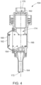
FIG. 4 illustrates a sectional view of the dispenser ofFIG. 1 , in accordance with an embodiment of the disclosure. - In the following description, for purposes of explanation, numerous specific details are set forth in order to provide a thorough understanding of the present disclosure. It will be apparent, however, to one skilled in the art that the present disclosure can be practiced without these specific details. In other instances, apparatus and methods are shown in block diagram form only in order to avoid obscuring the present disclosure.
- Reference in this specification to "one embodiment" or "an embodiment" means that a particular feature, structure, or characteristic described in connection with the embodiment is included in at least one embodiment of the present disclosure. The appearance of the phrase "in one embodiment" in various places in the specification are not necessarily all referring to the same embodiment, nor are separate or alternative embodiments mutually exclusive of other embodiments. Further, the terms "a" and "an" herein do not denote a limitation of quantity, but rather denote the presence of at least one of the referenced items. Moreover, various features are described which may be exhibited by some embodiments and not by others. Similarly, various requirements are described which may be requirements for some embodiments but not for other embodiments.
- Some embodiments of the present disclosure will now be described more fully hereinafter with reference to the accompanying drawings, in which some, but not all, embodiments of the disclosure are shown. Indeed, various embodiments of the disclosure may be embodied in many different forms and should not be construed as limited to the embodiments set forth herein; rather, these embodiments are provided so that this disclosure will satisfy applicable legal requirements. Like reference numerals refer to like elements throughout. The use of any term should not be taken to limit the spirit and scope of embodiments of the present disclosure.
- The embodiments are described herein for illustrative purposes and are subject to many variations. It is understood that various omissions and substitutions of equivalents are contemplated as circumstances may suggest or render expedient but are intended to cover the application or implementation without departing from the spirit or the scope of the present disclosure. Further, it is to be understood that the phraseology and terminology employed herein are for the purpose of the description and should not be regarded as limiting. Any heading utilized within this description is for convenience only and has no legal or limiting effect.
- Referring to
FIG. 1 andFIG. 2 , apouch assembly 100 suitable for storing and dispensing a fluid is shown. Thepouch assembly 100 includes apouch 102 and adispenser 104 that controls a dispensing of the fluid from thepouch 102 when thepouch 102 is arranged in an inverted position, as shown inFIG. 1 . Referring toFIGS. 1 to 3 , thepouch 102 is a flexible pouch and may be made of a flexible material adapted to be squeezed to a collapsed configuration. It may be appreciated that the fluid may be dispensed/removed, under the influence of gravity, from thepouch 102 by simply disposing thepouch 102 in an inverted position. However, in some embodiments, the dispensing of the fluid, in the inverted position, may be controlled using thedispenser 104 as discussed later in the description. - As shown in
FIGS. 2 to 3 , thepouch 102 includes ahousing 110 defining achamber 112 to store a liquid. Thehousing 110 includes a base 114 having anouter edge 116, and at least one wall, for example, a pair ofsidewalls 118 extending vertically, in a first direction, from theouter edge 116 of thebase 114. The pair ofsidewalls 118 are arranged opposite to each other, and side edges of thesidewalls 118 are attached/coupled/fused with each other. In an embodiment, thebase 114 includes an oval shape in an inflated configuration (shown inFIG. 2 ) i.e., when the fluid is disposed inside thechamber 112. Thebase 114 and hence thehousing 110 collapses on itself in response to exit of the fluid from thechamber 112, and may be arranged in a collapsed configuration when thepouch 102 becomes empty. In the collapsed configuration (shown inFIG. 1 ), at some portions of thesidewalls 118 may be arranged abutting each other such that thebase 114 is also folded along a center line such thatbase 114 is disposed between lower portions of thesidewalls 118. - The
housing 110 further includes at least one support wall, for example, twosupport walls outer edge 116 of the base 114 to enable a self-standing of thepouch 102. As shown, at least one of thesupport walls opening 126 to facilitate a hanging of thepouch 102 in an inverted position using a suitable hook. For hanging thepouch 102 in the inverted position, an end of the hook or mount is inserted into theopening 126, while other end of the hook is coupled to a suitable mounting structure. - Further, the
housing 110 includes atop structure 130 arranged opposite to the base 114 such that thechamber 112 is defined between the base 114, thesidewalls 118 and thetop structure 130. In the illustrated embodiment, thetop structure 130 is atop edge 132 of thehousing 110 formed/defined by joining top edges of thesidewalls 118. As shown, thetop structure 130 includes a firsttop portion 134, for example, a firsttop edge portion 134, extending substantially horizontally and parallel to thebase 114, and a secondtop portion 136, for example, a secondtop edge portion 136, extending at an angle 'A' relative to the first top portion. The firsttop edge portion 134 extends from afirst side edge 138 towards asecond side edge 139, while the secondtop edge portion 136 extends from the firsttop edge portion 134 to thesecond side edge 139. - In some embodiments, the angle of inclination of the second
top edge portion 136 relative to thefirst edge portion 134 is between 7 degrees and 38 degrees. In some embodiments, the angle of inclination is between 10 degrees and 25 degrees. In some embodiments, the angle of inclination is 15 degrees. Alternatively, the angle of inclination is 25 degrees. Such angle of inclination, for example, 15 degrees angle of inclination, enables smooth filling of thepouch 102 on a fluid filling line and easy packaging. Moreover, such angle of inclination enables thepouch 102 to be used as a dispensing unit in the inverted position to enable dispensing of fluid using a suitable dispenser, for example, thedispenser 104. - Further, the
housing 110 defines anopening 140 that extends along the secondtop edge portion 136 to enable an exit of the fluid from thechamber 112 as well as entry of the fluid inside thechamber 112. To facilitate a filling of thechamber 112 and exit of the fluid from thechamber 112, thepouch 102 includes aspout 150 engaged/coupled/attached with thehousing 110 and extending through theopening 140. Thespout 150 is arranged substantially perpendicularly to the secondtop edge portion 136 of thehousing 110. Accordingly, a center line of thespout 150 is arranged at an angle 'B' relative to a centerline of thehousing 110. The angle `B" is identical to the angle 'A". In an embodiment, thespout 150 includes afirst portion 152 extending inside thehousing 110 and coupled to thesidewalls 118 of thehousing 110, and asecond portion 154 arranged external to thehousing 110. As shown inFIG. 2 , thefirst portion 152 may include aflange 156 defining a first port (not shown) of thespout 150. Theflange 156 is arranged inside thehousing 110 and is coupled to the secondtop edge portion 136, while thesecond portion 154 defines a second port (not shown) of thespout 150. The fluid flows to and from thechamber 112 via the first port and the second port. To cover the second port, thepouch 102 may include a cap (not shown) adapted to be threadably engaged or press fitted to thesecond portion 154 of thespout 150. - Referring to
FIG. 1 , thedispenser 104 is adapted to be removably engaged with thespout 150 and is configured to control an exit of the fluid from thechamber 112 when thepouch 102 is arranged in an inverted position. Thedispenser 104 is adapted to be actuated manually using fingers and includes acap portion 162, anozzle portion 164, and apump portion 166 arranged between thecap portion 162 and thenozzle portion 164. Thecap portion 162 is configured to be coupled to thesecond portion 154 of thespout 150 and defines aninlet 170, as shown inFIG. 4 , of thedispenser 104 to receive the fluid from thespout 150 when thepouch 102 is arranged in the inverted position. In an embodiment, thecap portion 162 is press fitted to thesecond portion 154 of thespout 150. Alternatively, thecap portion 162 may be in threaded engagement with thespout 150. - As shown in
FIG. 4 , thenozzle portion 164 defines anoutlet 172 of thedispenser 104 and thepump portion 166 defines apump chamber 174 to temporarily store the fluid received from thepouch 102. Thepump portion 166 also includes anactuator 180, for example, alid 182, adapted to be pressed/actuated by the user to enable a flow of the fluid from thepump chamber 174 to theoutlet 172. As shown inFIG. 4 , thelid 182 is formed of a material that is elastically deformable to enable a movement of at least a portion of thelid 182 from an outward position to an inward position when pressed by the user. Thepump portion 166 further includes a biasingmember 184, for example, a spring, configured to restore thelid 182 from the inward position to the outward (i.e., original) position, when the fingers are released. Some specific details of one dispenser are disclosed and described in detail in applicants pending patent applications no.EP4036032A1 andEP4036404A1 filed with the European patent office. These applications are incorporated by reference in its entirety. - Many modifications and other embodiments of the disclosures set forth herein will come to mind to one skilled in the art to which these disclosures pertain having the benefit of the teachings presented in the foregoing descriptions and the associated drawings. Therefore, it is to be understood that the disclosures are not to be limited to the specific embodiments disclosed and that modifications and other embodiments are intended to be included within the scope of the appended claims. Moreover, although the foregoing descriptions and the associated drawings describe example embodiments in the context of certain example combinations of elements and/or functions, it should be appreciated that different combinations of elements and/or functions may be provided by alternative embodiments without departing from the scope of the appended claims. In this regard, for example, different combinations of elements and/or functions than those explicitly described above are also contemplated as may be set forth in some of the appended claims. Although specific terms are employed herein, they are used in a generic and descriptive sense only and not for purposes of limitation.
Claims (15)
- A pouch (102), comprising:a housing (110) defining a chamber (112) to store a liquid and including a top structure (130) having a first top portion (134) extending substantially horizontally and a second top portion (136) extending at an angle relative to the first top portion (134); anda spout (150) coupled to the second top portion (136) and arranged substantially perpendicularly to the second top portion (136) and extending external to the housing (110) from the chamber (112) to enable ingress and egress of the liquid from the chamber (112), characterized in thatthe angle of the second top portion (136) relative to the first top portion (134) is between 7 degrees and 38 degrees.
- The pouch (102) of claim 1, wherein the angle of the second top portion (136) relative to the first top portion (134) is between 10 degrees and 25 degrees.
- The pouch (102) of any one of preceding claims, wherein the angle of the second top portion (136) relative to the first top portion (134) is 15 degrees or 25 degrees.
- The pouch (100) of any one of preceding claims, wherein the housing (110) includesa base (114) having an outer edge (116), anda pair of sidewalls (118) arranged opposite to each other and extending vertically upwardly from the outer edge (116) of the base (114), wherein side edges of the pair of sidewalls (118) are connected to each other, and top edges of the pair of sidewalls (118) are connected to each other defining the top structure (130) of the housing (110).
- The pouch (102) of any one of preceding claims, wherein the housing (110) includes at least one support wall (122, 124) extending downwardly form the outer edge (116) of the base (114) to enable a self-standing of the pouch (102) on a surface.
- The pouch (102) of claim 5, wherein the at least one support wall (122, 124) defines at least one opening (126) to enable a hanging of the pouch (102) in an inverted position.
- The pouch of any one of preceding claims, wherein the housing is a flexible housing.
- A pouch assembly (1000, comprising:a pouch (102) includinga housing (110) defining a chamber (1120 to store the liquid and including a top structure (130) having a first top portion (134) arranged substantially horizontally and a second top portion (136) extending at an angle relative to the first top portion (136), wherein the angle of the second top portion (136) relative to the first top portion (134) is between 7 degrees to 38 degrees, anda spout (150) coupled to the second top portion (136) and arranged substantially perpendicularly to the second top portion (136) and extending external to the housing (110) from the chamber (112); anda dispenser (104) adapted to be engaged with the spout (150) and configured to control an exit of liquid from the chamber when the pouch (102) is arranged in an inverted position.
- The pouch assembly (100) of claim 8, wherein the dispenser (104) includesa cap portion (162) configured to be engaged with the spout (150),a nozzle portion (164) defining an outlet (172) of the dispenser (104), anda pump portion (166) arranged between the cap portion (162) and the nozzle portion (164) and defining a pump chamber (174) to store the liquid received from the pouch (102) when the pouch (1020 is arranged in the inverted position, the pump portion (166) includes a lid (182) adapted to be pressed to an inward position to enable a flow of the liquid from the pump chamber (174) to the nozzle portion (164).
- The pouch assembly (100) of claim 9, wherein the lid (182) is biased to an outward position, wherein in the outward position, the lid (1820 prevents the flow of liquid from the pump chamber (174) to the nozzle portion (164).
- The pouch assembly (100) of any one of preceding claims, wherein the angle of the second top portion (136) relative to the first top portion (134) is between 10 degrees and 25 degrees.
- The pouch assembly (100) of any one of preceding claims, wherein the angle of the second top portion (136) relative to the first top portion (134) is 15 degrees or 25 degrees.
- The pouch assembly (100) of any one of preceding claims, wherein the housing (110) includesa base (114) having an outer edge (116), anda pair of sidewalls (118) arranged opposite to each other and extending vertically upwardly from the outer edge (116) of the base (114), wherein side edges of the pair of sidewalls (118) are connected to each other, and top edges of the pair of sidewalls (118) are connected to each other defining the top structure (130) of the housing (110).
- The pouch assembly (100) of claim 13, wherein the housing (110) includes at least one support wall (122, 124) extending downwardly form the outer edge (116) of the base (114) to enable a self-standing of the pouch (102) on a surface.
- The pouch assembly (100) of claim 14, wherein the at least one support wall (122, 124) defines at least one opening (126) to enable a hanging of the pouch (102) in the inverted position.
Priority Applications (1)
| Application Number | Priority Date | Filing Date | Title |
|---|---|---|---|
| EP23170976.7A EP4458722A1 (en) | 2023-05-02 | 2023-05-02 | Pouch |
Applications Claiming Priority (1)
| Application Number | Priority Date | Filing Date | Title |
|---|---|---|---|
| EP23170976.7A EP4458722A1 (en) | 2023-05-02 | 2023-05-02 | Pouch |
Publications (1)
| Publication Number | Publication Date |
|---|---|
| EP4458722A1 true EP4458722A1 (en) | 2024-11-06 |
Family
ID=86328585
Family Applications (1)
| Application Number | Title | Priority Date | Filing Date |
|---|---|---|---|
| EP23170976.7A Withdrawn EP4458722A1 (en) | 2023-05-02 | 2023-05-02 | Pouch |
Country Status (1)
| Country | Link |
|---|---|
| EP (1) | EP4458722A1 (en) |
Citations (7)
| Publication number | Priority date | Publication date | Assignee | Title |
|---|---|---|---|---|
| JP2000281061A (en) * | 1999-03-30 | 2000-10-10 | Tokiko Harano | Nozzle with cutter |
| US20040079764A1 (en) * | 2002-10-23 | 2004-04-29 | Balz Eric R. | Upright product outlet bag evacuation packaging |
| WO2004108545A1 (en) * | 2003-06-03 | 2004-12-16 | Fujimori Kogyo Co., Ltd. | Bag for packaging liquid food |
| DE102014109633A1 (en) * | 2014-07-09 | 2016-01-14 | IfP Privates Institut für Produktqualität GmbH | dispatch bag |
| JP2018039545A (en) * | 2016-09-09 | 2018-03-15 | 大日本印刷株式会社 | Pouch for refilling |
| EP4036404A1 (en) | 2019-09-25 | 2022-08-03 | Kao Corporation | Dispenser |
| EP4036032A1 (en) | 2019-09-25 | 2022-08-03 | Kao Corporation | Dispenser |
-
2023
- 2023-05-02 EP EP23170976.7A patent/EP4458722A1/en not_active Withdrawn
Patent Citations (7)
| Publication number | Priority date | Publication date | Assignee | Title |
|---|---|---|---|---|
| JP2000281061A (en) * | 1999-03-30 | 2000-10-10 | Tokiko Harano | Nozzle with cutter |
| US20040079764A1 (en) * | 2002-10-23 | 2004-04-29 | Balz Eric R. | Upright product outlet bag evacuation packaging |
| WO2004108545A1 (en) * | 2003-06-03 | 2004-12-16 | Fujimori Kogyo Co., Ltd. | Bag for packaging liquid food |
| DE102014109633A1 (en) * | 2014-07-09 | 2016-01-14 | IfP Privates Institut für Produktqualität GmbH | dispatch bag |
| JP2018039545A (en) * | 2016-09-09 | 2018-03-15 | 大日本印刷株式会社 | Pouch for refilling |
| EP4036404A1 (en) | 2019-09-25 | 2022-08-03 | Kao Corporation | Dispenser |
| EP4036032A1 (en) | 2019-09-25 | 2022-08-03 | Kao Corporation | Dispenser |
Similar Documents
| Publication | Publication Date | Title |
|---|---|---|
| US5649643A (en) | Flexible container having a retractable dispenser | |
| US4645097A (en) | Sidewall dispenser | |
| JP4944164B2 (en) | Container for storing and retrieving bulk materials | |
| US8944288B2 (en) | Collapsible container | |
| US20140263421A1 (en) | Counter mount above-counter fill dispensing systems and refill units for same | |
| NZ236700A (en) | Measuring chamber to be attached to the neck of a container | |
| JP7248570B2 (en) | package | |
| US5279450A (en) | Container with two separate chambers | |
| JP6906889B2 (en) | Liquid dispenser | |
| US5516007A (en) | Dispenser | |
| US9522404B2 (en) | Flowable dispensers, systems, and filling processes | |
| AU2005243738A1 (en) | Apparatus for filling and refilling a flexible container | |
| JP2007119069A5 (en) | ||
| JP2024054439A (en) | Standing pouch container provided with pump function | |
| US20220055051A1 (en) | Fluid dispenser | |
| JP2019085112A (en) | Ink storage bottle | |
| US6039214A (en) | Material dispensing system | |
| US3368721A (en) | Liquid dispensing container | |
| US5346108A (en) | Gaged dispensing apparatus | |
| US8220667B1 (en) | Dispensing unit for dispensing fluid material prepackaged in a container | |
| JP2017145011A (en) | Dispenser container with pump | |
| JP7274136B1 (en) | Empty device for refillable container and refillable container including same | |
| US5505340A (en) | Apparatus for discharging a controlled quantity of a hair care preparation | |
| WO1992021569A1 (en) | Inverted dispenser | |
| GB2448969A (en) | Fluid dispensing bags |
Legal Events
| Date | Code | Title | Description |
|---|---|---|---|
| PUAI | Public reference made under article 153(3) epc to a published international application that has entered the european phase |
Free format text: ORIGINAL CODE: 0009012 |
|
| STAA | Information on the status of an ep patent application or granted ep patent |
Free format text: STATUS: THE APPLICATION HAS BEEN PUBLISHED |
|
| AK | Designated contracting states |
Kind code of ref document: A1 Designated state(s): AL AT BE BG CH CY CZ DE DK EE ES FI FR GB GR HR HU IE IS IT LI LT LU LV MC ME MK MT NL NO PL PT RO RS SE SI SK SM TR |
|
| STAA | Information on the status of an ep patent application or granted ep patent |
Free format text: STATUS: THE APPLICATION IS DEEMED TO BE WITHDRAWN |
|
| 18D | Application deemed to be withdrawn |
Effective date: 20250507 |