EP4458694A1 - Strapping tool - Google Patents
Strapping tool Download PDFInfo
- Publication number
- EP4458694A1 EP4458694A1 EP24163144.9A EP24163144A EP4458694A1 EP 4458694 A1 EP4458694 A1 EP 4458694A1 EP 24163144 A EP24163144 A EP 24163144A EP 4458694 A1 EP4458694 A1 EP 4458694A1
- Authority
- EP
- European Patent Office
- Prior art keywords
- shaft
- press
- servo
- axle
- strapping tool
- Prior art date
- Legal status (The legal status is an assumption and is not a legal conclusion. Google has not performed a legal analysis and makes no representation as to the accuracy of the status listed.)
- Granted
Links
Images




Classifications
-
- B—PERFORMING OPERATIONS; TRANSPORTING
- B65—CONVEYING; PACKING; STORING; HANDLING THIN OR FILAMENTARY MATERIAL
- B65B—MACHINES, APPARATUS OR DEVICES FOR, OR METHODS OF, PACKAGING ARTICLES OR MATERIALS; UNPACKING
- B65B13/00—Bundling articles
- B65B13/02—Applying and securing binding material around articles or groups of articles, e.g. using strings, wires, strips, bands or tapes
- B65B13/025—Hand-held tools
-
- B—PERFORMING OPERATIONS; TRANSPORTING
- B65—CONVEYING; PACKING; STORING; HANDLING THIN OR FILAMENTARY MATERIAL
- B65B—MACHINES, APPARATUS OR DEVICES FOR, OR METHODS OF, PACKAGING ARTICLES OR MATERIALS; UNPACKING
- B65B13/00—Bundling articles
- B65B13/18—Details of, or auxiliary devices used in, bundling machines or bundling tools
- B65B13/185—Details of tools
-
- B—PERFORMING OPERATIONS; TRANSPORTING
- B65—CONVEYING; PACKING; STORING; HANDLING THIN OR FILAMENTARY MATERIAL
- B65B—MACHINES, APPARATUS OR DEVICES FOR, OR METHODS OF, PACKAGING ARTICLES OR MATERIALS; UNPACKING
- B65B13/00—Bundling articles
- B65B13/18—Details of, or auxiliary devices used in, bundling machines or bundling tools
- B65B13/185—Details of tools
- B65B13/187—Motor means
Definitions
- the present invention relates to a strapping tool, and more particularly to a strapping tool having a press unit
- an electric packing tool For transporting goods, an electric packing tool is used for packing the goods.
- a conventional electric packing tool comprises a body.
- the body includes a cutting unit, a reeling unit, a press unit, a press plate, and a battery.
- the press unit includes a spindle.
- a hand-operated lever and a press block are provided at both ends of the spindle, respectively.
- the press block and the press plate are arranged oppositely. First, the user presses the hand-operated lever to rotate the spindle for lifting the press block. Then, one end of the packing strap is inserted between the press block and the press plate. After that, the user releases the hand-operated lever, such that the press block presses against the packing strap through a spring. Then, the other end of the packing strap passes through the cutting unit and the reeling unit. The packing strap is tightened by the reeling unit. Finally, the unnecessary packing strap is cut by the cutting unit to complete the packaging operation.
- the primary object of the present invention is to provide a strapping tool having a press unit, which can simply and effortlessly lift a press block of the press unit for a packing strap to pass therethrough or lower the press block to press the packing strap.
- the body includes a reeling unit, a cutting unit, and a press unit.
- the press unit includes a press plate.
- the press plate is fixed to a bottom of the body and extends outward.
- the body includes a grip portion and a mounting portion.
- a button is provided on the grip portion.
- the mounting portion is equipped with a power unit.
- the press unit includes a servo and an axle.
- the servo is electrically connected to the button.
- the servo has an output shaft.
- the output shaft is connected to a connecting shaft.
- the connecting shaft is connected to one side of the axle.
- the output shaft, the connecting shaft and the axle are rotated simultaneously.
- Another side of the axle is integrally formed with an eccentric shaft.
- the eccentric shaft extends outward.
- the eccentric shaft is fitted with a shaft seat.
- a press block is pivotally connected to the shaft seat.
- the servo when the button is pressed, the servo will lift the press block for a packing strap to pass therethrough; when the button is released, the servo will lower the press block to press against the packing strap.
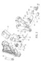
- FIG. 1 is a perspective view in accordance with a first embodiment of the present invention.
- FIG. 2 is an exploded view in accordance with the first embodiment of the present invention.
- the present invention discloses a strapping tool 100.
- the strapping tool 100 is a portable electric strapping tool.
- the strapping tool 100 comprises a body 10, a reeling unit 20, a cutting unit 30, and a press unit 40.
- the body 10 is a shell.
- the body 10 includes a grip portion 11 and a mounting portion 12.
- a first button 111 is provided on the top of the grip portion 11.
- a second button 112 is provided on the bottom of the grip portion 11.
- the mounting portion 12 is equipped with a power unit 13.
- the power unit is a battery.
- the first button 111, the second button 112, and the electrical unit 13 are electrically connected to a control module 14.
- the reeling unit 20 is disposed on the body 10.
- the reeling unit 20 includes a motor 21, a reduction gear set 22 that is a planetary gear set, a worm rod 23, and a spindle 24.
- the motor 21 is electrically connected to the second button 112 and the control module 14.
- the motor 21, the reduction gear set 22 and the spindle 23 are connected to one another.
- the spindle 24 is fitted with a worm wheel 25 and bearings located on both sides of the worm wheel 25.
- the worm rod 23 is meshed with the worm wheel 25.
- the spindle 24 has an extension portion 26 extending out of the body 10.
- the extension portion 26 has a pair of grooves 27 for a packing strap 200 to pass therethrough.
- the cutting unit 30 is disposed on the body 10.
- the cutting unit 30 includes a hollow blade tube 31 and a blade shaft 32.
- the blade tube 31 has an extension portion 33 extending out of the body 10.
- the extension portion 33 has a pair of grooves 34 for the packing strap 200 to pass therethrough.
- the blade shaft 32 is rotatably connected in the blade tube 31.
- a handle 36 is connected to a fixed end 35 of the blade shaft 32 in the radial direction. The handle 36 is configured to drive the blade shaft 32 to rotate, thereby cutting the packing strap 200.
- the press unit 40 is disposed on the body 10.
- the press unit 40 includes a servo 41, a press plate 42, and an axle 43.
- the servo 41 is an actuator.
- the servo 41 is electrically connected to the first button 111 and the control module 14.
- the servo 41 has a servo motor (not shown in the figures) and an output shaft 411.
- the control module 14 controls the rotation angle of the output shaft 411 of the servo 41.
- the output shaft 411 is connected to a connecting shaft 44 through a screw (not shown in the figures), so that the output shaft 411 and the connecting shaft 44 are rotated simultaneously.
- the connecting shaft 44 is a sleeve.
- the outer peripheral wall of the connecting shaft 44 has a recess 441.
- the press plate 42 is fixed to the bottom of the body 10 and extends outward.
- An axle seat 421 is provided on the press plate 42.
- the axle seat 421 has an axle hole 422.
- the axle 43 is inserted in the axle hole 422.
- the axle 43 has a connecting hole 431.
- the connecting shaft 44 is disposed in the connecting hole 431.
- the axle 43 is provided with a stop screw (not shown) and is pressed against the recess 441, so that the connecting shaft 44 and the axle 43 are rotated simultaneously.
- the other side of the axle 43 is integrally formed with an eccentric shaft 432.
- the eccentric shaft 432 extends outward.
- the eccentric shaft 432 is fitted with a shaft seat 45.
- the shaft seat 45 is connected to the eccentric shaft 432 through a screw (not shown in the figures).
- a pivot 46 is insertedly connected to the shaft seat 45 for pivoting a press block 47.
- the first button 111 is pressed to start the servo 41 to rotate the output shaft 411 clockwise and drive the connecting shaft 44, the axle 43, the eccentric shaft 432, the shaft seat 45, and the press block 47.
- the press block 47 is lifted, so that the press block 47 is moved away from the press plate 42.
- the packing strap 200 is inserted between the press block 47 and the press plate 42, and then the first button 111 is released.
- the servo 41 rotates the output shaft 411 counterclockwise to lower the press block 47 so that the press block 47 presses against the packing strap 200.
- the packing strap 200 is inserted in the blade tube 31 and the spindle 24.
- the second button 112 is pressed for the spindle 24 to reel the packing strap, thereby tightening the packing strap 200.
- the handle 36 is operated to rotate the blade shaft 32 for cutting the packing strap 200.
- the first button 111 is pressed again to lift the press block 47, so that the packaging operation is completed.
- the servo 41 is controlled by the first button 111 to lift the press block 47 for the packing strap to pass therethrough or to lower the press block 47 for pressing the packing strap.
- the first button 111 and the second button 112 of the present invention are disposed on the top and the bottom of the grip portion 11, respectively.
- the user may press the first button 111 with his/her thumb or press the second button 112 with his/her index finger without changing the holding manner when holding the grip portion 11.
- the strapping tool provided by the present invention has the effect of improving the quality and efficiency of packaging operations.
- FIG. 6 is a partial exploded view in accordance with a second embodiment of the present invention.
- the second embodiment of the present invention is substantially similar to the aforementioned first embodiment with the exceptions described hereinafter.
- the servo 41 further includes a linking member 48.
- the linking member 48 has a first linking ring 481, a second linking ring 482, and a connecting rod 483.
- the first linking ring 481 is sleeved on the connecting shaft 44 and secured by a stop screw (not shown in the figures) or a C-shaped snap (not shown in the figures), so that the first linking ring 481 and the connecting shaft 44 are rotated simultaneously.
- the second linking ring 482 is sleeved on the fixed end 35 of the blade shaft 32.
- the cross section of the fixed end 35 of the blade shaft 32 is non-circular.
- the second linking ring 482 has a non-circular through hole 484.
- the cross section of the fixed end 35 corresponds to the shape of the through hole 484, so that the second linking ring 482 and the blade shaft 32 are rotated simultaneously.
- the first linking ring 481 and the second linking ring 482 are pivoted at both ends of the connecting rod 483 through positioning pins 485 respectively, so that the first linking ring 481 and the second linking ring 482 are driven to rotate. Thereby, the servo 41 can rotate the blade shaft 32 through the linking member 48 without using the handle 36.
- the servo 41 When the first button 111 is pressed, the servo 41 will lift the press block 47 for the packing strap to pass therethrough and rotate the blade shaft 32. When the first button 111 is released, as shown in FIG. 7 , the servo 41 will lower the press block 47 to press against the packing strap 200 and the press plate 42. The blade shaft 32 is placed flat for the packing strap 200 to be inserted in the blade tube 31. Finally, as shown in FIG. 8 , when the first button 111 is pressed again, the servo 41 will rotate the blade shaft 32 to cut the packing strap 200 and the press block 47 will be lifted, so that the packaging operation is completed.
Landscapes
- Engineering & Computer Science (AREA)
- Mechanical Engineering (AREA)
- Basic Packing Technique (AREA)
Abstract
Description
- The present invention relates to a strapping tool, and more particularly to a strapping tool having a press unit
- For transporting goods, an electric packing tool is used for packing the goods. A conventional electric packing tool comprises a body. The body includes a cutting unit, a reeling unit, a press unit, a press plate, and a battery. The press unit includes a spindle. A hand-operated lever and a press block are provided at both ends of the spindle, respectively. The press block and the press plate are arranged oppositely. First, the user presses the hand-operated lever to rotate the spindle for lifting the press block. Then, one end of the packing strap is inserted between the press block and the press plate. After that, the user releases the hand-operated lever, such that the press block presses against the packing strap through a spring. Then, the other end of the packing strap passes through the cutting unit and the reeling unit. The packing strap is tightened by the reeling unit. Finally, the unnecessary packing strap is cut by the cutting unit to complete the packaging operation.
- However, it is necessary for the user to operate the hand-operated lever of the conventional electric strapping tool before and after the goods are packed by the strapping tool. In addition to the smoothness of the strapping operation, it is required to consider the stability of holding the electric strapping tool. As a result, it is more complicated and inconvenient to use the electric strapping tool. Accordingly, the inventor of the present invention has devoted himself based on his many years of practical experiences to solve these problems.
- The primary object of the present invention is to provide a strapping tool having a press unit, which can simply and effortlessly lift a press block of the press unit for a packing strap to pass therethrough or lower the press block to press the packing strap.
- In order to achieve the forgoing object, the strapping tool provided by the present invention comprises a main body. The body includes a reeling unit, a cutting unit, and a press unit. The press unit includes a press plate. The press plate is fixed to a bottom of the body and extends outward. The body includes a grip portion and a mounting portion. A button is provided on the grip portion. The mounting portion is equipped with a power unit. The press unit includes a servo and an axle. The servo is electrically connected to the button. The servo has an output shaft. The output shaft is connected to a connecting shaft. The connecting shaft is connected to one side of the axle. The output shaft, the connecting shaft and the axle are rotated simultaneously. Another side of the axle is integrally formed with an eccentric shaft. The eccentric shaft extends outward. The eccentric shaft is fitted with a shaft seat. A press block is pivotally connected to the shaft seat.
- As to the strapping tool provided by the present invention, when the button is pressed, the servo will lift the press block for a packing strap to pass therethrough; when the button is released, the servo will lower the press block to press against the packing strap.
-
-
FIG. 1 is a perspective view in accordance with a first embodiment of the present invention; -
FIG. 2 is an exploded view in accordance with the first embodiment of the present invention; -
FIG. 3 is a schematic view in accordance with the first embodiment of the present invention when in use, wherein the press block is lifted; -
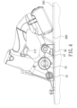
FIG. 4 is a schematic view in accordance with the first embodiment of the present invention when in use, wherein the press block is lowered; -
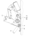
FIG. 5 is a schematic view in accordance with the first embodiment of the present invention when in use, wherein the packing strap is cut; -
FIG. 6 is a partial exploded view in accordance with a second embodiment of the present invention; -
FIG. 7 is a schematic view in accordance with the second embodiment of the present invention when in use, wherein the blade shaft is placed flat; and -
FIG. 8 is a schematic view in accordance with the second embodiment of the present invention when in use, wherein the blade shaft is rotated. - Embodiments of the present invention will now be described, by way of example only, with reference to the accompanying drawings.
-
FIG. 1 is a perspective view in accordance with a first embodiment of the present invention.FIG. 2 is an exploded view in accordance with the first embodiment of the present invention. The present invention discloses astrapping tool 100. In a preferred embodiment, thestrapping tool 100 is a portable electric strapping tool. Thestrapping tool 100 comprises abody 10, areeling unit 20, acutting unit 30, and apress unit 40. - The
body 10 is a shell. Thebody 10 includes agrip portion 11 and amounting portion 12. Afirst button 111 is provided on the top of thegrip portion 11. Asecond button 112 is provided on the bottom of thegrip portion 11. Themounting portion 12 is equipped with apower unit 13. The power unit is a battery. Thefirst button 111, thesecond button 112, and theelectrical unit 13 are electrically connected to acontrol module 14. - The
reeling unit 20 is disposed on thebody 10. Thereeling unit 20 includes amotor 21, areduction gear set 22 that is a planetary gear set, aworm rod 23, and aspindle 24. Themotor 21 is electrically connected to thesecond button 112 and thecontrol module 14. Themotor 21, the reduction gear set 22 and thespindle 23 are connected to one another. Thespindle 24 is fitted with aworm wheel 25 and bearings located on both sides of theworm wheel 25. Theworm rod 23 is meshed with theworm wheel 25. Thespindle 24 has anextension portion 26 extending out of thebody 10. Theextension portion 26 has a pair ofgrooves 27 for apacking strap 200 to pass therethrough. When thesecond button 112 is pressed, themotor 21 drives the reduction gear set 22, theworm rod 23, theworm wheel 25 and thespindle 24, and thespindle 24 is rotated to tighten thepacking strap 200. - The cutting
unit 30 is disposed on thebody 10. The cuttingunit 30 includes ahollow blade tube 31 and ablade shaft 32. Theblade tube 31 has anextension portion 33 extending out of thebody 10. Theextension portion 33 has a pair ofgrooves 34 for the packingstrap 200 to pass therethrough. Theblade shaft 32 is rotatably connected in theblade tube 31. Ahandle 36 is connected to afixed end 35 of theblade shaft 32 in the radial direction. Thehandle 36 is configured to drive theblade shaft 32 to rotate, thereby cutting the packingstrap 200. - The
press unit 40 is disposed on thebody 10. Thepress unit 40 includes aservo 41, apress plate 42, and anaxle 43. Theservo 41 is an actuator. Theservo 41 is electrically connected to thefirst button 111 and thecontrol module 14. Theservo 41 has a servo motor (not shown in the figures) and anoutput shaft 411. Thecontrol module 14 controls the rotation angle of theoutput shaft 411 of theservo 41. Theoutput shaft 411 is connected to a connectingshaft 44 through a screw (not shown in the figures), so that theoutput shaft 411 and the connectingshaft 44 are rotated simultaneously. The connectingshaft 44 is a sleeve. The outer peripheral wall of the connectingshaft 44 has arecess 441. Thepress plate 42 is fixed to the bottom of thebody 10 and extends outward. Anaxle seat 421 is provided on thepress plate 42. Theaxle seat 421 has anaxle hole 422. Theaxle 43 is inserted in theaxle hole 422. Theaxle 43 has a connectinghole 431. The connectingshaft 44 is disposed in the connectinghole 431. Theaxle 43 is provided with a stop screw (not shown) and is pressed against therecess 441, so that the connectingshaft 44 and theaxle 43 are rotated simultaneously. The other side of theaxle 43 is integrally formed with aneccentric shaft 432. Theeccentric shaft 432 extends outward. Theeccentric shaft 432 is fitted with ashaft seat 45. Theshaft seat 45 is connected to theeccentric shaft 432 through a screw (not shown in the figures). Apivot 46 is insertedly connected to theshaft seat 45 for pivoting apress block 47. - Please refer to
FIG. 3 in cooperation withFIG. 2 . When in use, first, thefirst button 111 is pressed to start theservo 41 to rotate theoutput shaft 411 clockwise and drive the connectingshaft 44, theaxle 43, theeccentric shaft 432, theshaft seat 45, and thepress block 47. Thereby, thepress block 47 is lifted, so that thepress block 47 is moved away from thepress plate 42. As shown inFIG. 4 , at this time, the packingstrap 200 is inserted between thepress block 47 and thepress plate 42, and then thefirst button 111 is released. Theservo 41 rotates theoutput shaft 411 counterclockwise to lower thepress block 47 so that thepress block 47 presses against the packingstrap 200. Then, after anarticle 201 is packed by the packingstrap 200, the packingstrap 200 is inserted in theblade tube 31 and thespindle 24. Thesecond button 112 is pressed for thespindle 24 to reel the packing strap, thereby tightening the packingstrap 200. Finally, as shown inFIG. 5 , thehandle 36 is operated to rotate theblade shaft 32 for cutting the packingstrap 200. Thefirst button 111 is pressed again to lift thepress block 47, so that the packaging operation is completed. In the present invention, theservo 41 is controlled by thefirst button 111 to lift thepress block 47 for the packing strap to pass therethrough or to lower thepress block 47 for pressing the packing strap. Besides, thefirst button 111 and thesecond button 112 of the present invention are disposed on the top and the bottom of thegrip portion 11, respectively. The user may press thefirst button 111 with his/her thumb or press thesecond button 112 with his/her index finger without changing the holding manner when holding thegrip portion 11. In this way, the strapping tool provided by the present invention has the effect of improving the quality and efficiency of packaging operations. -
FIG. 6 is a partial exploded view in accordance with a second embodiment of the present invention. The second embodiment of the present invention is substantially similar to the aforementioned first embodiment with the exceptions described hereinafter. Theservo 41 further includes a linkingmember 48. The linkingmember 48 has afirst linking ring 481, asecond linking ring 482, and a connectingrod 483. Thefirst linking ring 481 is sleeved on the connectingshaft 44 and secured by a stop screw (not shown in the figures) or a C-shaped snap (not shown in the figures), so that thefirst linking ring 481 and the connectingshaft 44 are rotated simultaneously. Thesecond linking ring 482 is sleeved on thefixed end 35 of theblade shaft 32. In this embodiment, the cross section of thefixed end 35 of theblade shaft 32 is non-circular. Thesecond linking ring 482 has a non-circular throughhole 484. The cross section of thefixed end 35 corresponds to the shape of the throughhole 484, so that thesecond linking ring 482 and theblade shaft 32 are rotated simultaneously. Thefirst linking ring 481 and thesecond linking ring 482 are pivoted at both ends of the connectingrod 483 throughpositioning pins 485 respectively, so that thefirst linking ring 481 and thesecond linking ring 482 are driven to rotate. Thereby, theservo 41 can rotate theblade shaft 32 through the linkingmember 48 without using thehandle 36. When thefirst button 111 is pressed, theservo 41 will lift thepress block 47 for the packing strap to pass therethrough and rotate theblade shaft 32. When thefirst button 111 is released, as shown inFIG. 7 , theservo 41 will lower thepress block 47 to press against the packingstrap 200 and thepress plate 42. Theblade shaft 32 is placed flat for the packingstrap 200 to be inserted in theblade tube 31. Finally, as shown inFIG. 8 , when thefirst button 111 is pressed again, theservo 41 will rotate theblade shaft 32 to cut the packingstrap 200 and thepress block 47 will be lifted, so that the packaging operation is completed. - Although particular embodiments of the present invention have been described in detail for purposes of illustration, various modifications and enhancements may be made without departing from the spirit and scope of the present invention. Accordingly, the present invention is not to be limited except as by the appended claims.
Claims (7)
- A strapping tool, comprising a body, the body including a reeling unit, a cutting unit and a press unit, the press unit including a press plate, the press plate being fixed to a bottom of the body and extending outward; characterized by:the body including a grip portion and a mounting portion, a button being provided on the grip portion, the mounting portion being equipped with a power unit;the press unit including a servo and an axle, the servo being electrically connected to the button, the servo having an output shaft, the output shaft being connected to a connecting shaft, the connecting shaft being connected to one side of the axle, the output shaft, the connecting shaft and the axle being rotated simultaneously, another side of the axle being integrally formed with an eccentric shaft, the eccentric shaft extending outward, the eccentric shaft being fitted with a shaft seat, a press block being pivotally connected to the shaft seat.
- The strapping tool as claimed in claim 1, wherein when the button is pressed to start the servo to rotate the output shaft, the press block is lifted to move away from the press plate; when the button is released, the servo rotates the output shaft to lower the press block for the press block to press against a packing strap.
- The strapping tool as claimed in claim 1, wherein the servo is an actuator.
- The strapping tool as claimed in claim 1, wherein an axle seat is provided on the press plate, the axle seat has an axle hole, and the axle is inserted in the axle hole.
- The strapping tool as claimed in claim 1, wherein the cutting unit includes a blade tube and a blade shaft, the blade shaft is inserted in the blade tube, the servo further includes a linking member, the linking member is connected to the blade shaft, and the servo drives the blade shaft to rotate.
- The strapping tool as claimed in claim 5, wherein the linking member has a first linking ring, a second linking ring and a connecting rod, the first linking ring is sleeved on the connecting shaft, the second linking ring is sleeved on a fixed end of the blade shaft, the first linking ring and the second linking ring are pivoted at two ends of the connecting rod respectively, such that the connecting shaft, the first linking ring, the connecting rod, the second linking ring and the blade shaft are driven to rotate together.
- The strapping tool as claimed in claim 5, wherein when the button is pressed, the servo rotates the blade shaft to cut a packing strap and lifts the press block to release the packing strap.
Applications Claiming Priority (1)
| Application Number | Priority Date | Filing Date | Title |
|---|---|---|---|
| TW112116304A TWI864725B (en) | 2023-05-02 | 2023-05-02 | Strapping machine belt pressing device |
Publications (2)
| Publication Number | Publication Date |
|---|---|
| EP4458694A1 true EP4458694A1 (en) | 2024-11-06 |
| EP4458694B1 EP4458694B1 (en) | 2026-01-28 |
Family
ID=90365114
Family Applications (1)
| Application Number | Title | Priority Date | Filing Date |
|---|---|---|---|
| EP24163144.9A Active EP4458694B1 (en) | 2023-05-02 | 2024-03-13 | Strapping tool |
Country Status (3)
| Country | Link |
|---|---|
| US (1) | US20240367830A1 (en) |
| EP (1) | EP4458694B1 (en) |
| TW (1) | TWI864725B (en) |
Families Citing this family (1)
| Publication number | Priority date | Publication date | Assignee | Title |
|---|---|---|---|---|
| TWI864726B (en) * | 2023-05-02 | 2024-12-01 | 元貝實業股份有限公司 | Strapping machine cutting mechanism |
Citations (6)
| Publication number | Priority date | Publication date | Assignee | Title |
|---|---|---|---|---|
| DE202014102576U1 (en) * | 2014-06-03 | 2014-07-03 | Hsiu-Man Yu-Chen | Belt tensioner with a cutting arrangement |
| WO2015162171A1 (en) * | 2014-04-22 | 2015-10-29 | Cordstrap B.V. | Electrically driven strapping device and assembly |
| DE202017000364U1 (en) * | 2017-01-23 | 2017-05-09 | Hsiu-Man Yu Chen | Belt press assembly for a packaging tool |
| US11053034B1 (en) * | 2019-02-11 | 2021-07-06 | Golden Bear LLC | Strapping tensioning tool |
| US20210309400A1 (en) * | 2020-04-07 | 2021-10-07 | Yang Bey Industrial Co., Ltd. | Packing tool capable of displaying tension |
| US20220297861A1 (en) * | 2019-08-30 | 2022-09-22 | Cordstrap B.V. | Method and device for tensioning |
Family Cites Families (9)
| Publication number | Priority date | Publication date | Assignee | Title |
|---|---|---|---|---|
| CN2266566Y (en) * | 1996-09-14 | 1997-11-05 | 泛源股份有限公司 | Portable binding machine |
| TW391408U (en) * | 1998-12-24 | 2000-05-21 | Jang Jie Huang | Portable electrical baling machine |
| CN2488817Y (en) * | 2001-06-06 | 2002-05-01 | 毛淦祥 | Portable strapping machine strap cutting device |
| TWM254260U (en) * | 2004-03-30 | 2005-01-01 | Skylark Group Ventures Inc | Structural assembled article with polystyrene and polypropylene substrate |
| US20160376041A1 (en) * | 2015-06-23 | 2016-12-29 | Signode Industrial Group Llc | Battery powered flat tensioner tool |
| US11130598B2 (en) * | 2018-02-21 | 2021-09-28 | Golden Bear LLC | Strapping tool |
| KR102226589B1 (en) * | 2020-10-27 | 2021-03-12 | 장근철 | Detachable auto packaging tool capable hetero band |
| KR102315941B1 (en) * | 2021-01-18 | 2021-10-22 | 장근철 | Auto strapping packaging tool having clamp fixing apparatus |
| TWM645330U (en) * | 2023-05-02 | 2023-08-21 | 元貝實業股份有限公司 | Band pressing device of strapping machine |
-
2023
- 2023-05-02 TW TW112116304A patent/TWI864725B/en active
-
2024
- 2024-03-07 US US18/597,922 patent/US20240367830A1/en active Pending
- 2024-03-13 EP EP24163144.9A patent/EP4458694B1/en active Active
Patent Citations (6)
| Publication number | Priority date | Publication date | Assignee | Title |
|---|---|---|---|---|
| WO2015162171A1 (en) * | 2014-04-22 | 2015-10-29 | Cordstrap B.V. | Electrically driven strapping device and assembly |
| DE202014102576U1 (en) * | 2014-06-03 | 2014-07-03 | Hsiu-Man Yu-Chen | Belt tensioner with a cutting arrangement |
| DE202017000364U1 (en) * | 2017-01-23 | 2017-05-09 | Hsiu-Man Yu Chen | Belt press assembly for a packaging tool |
| US11053034B1 (en) * | 2019-02-11 | 2021-07-06 | Golden Bear LLC | Strapping tensioning tool |
| US20220297861A1 (en) * | 2019-08-30 | 2022-09-22 | Cordstrap B.V. | Method and device for tensioning |
| US20210309400A1 (en) * | 2020-04-07 | 2021-10-07 | Yang Bey Industrial Co., Ltd. | Packing tool capable of displaying tension |
Also Published As
| Publication number | Publication date |
|---|---|
| TWI864725B (en) | 2024-12-01 |
| TW202444612A (en) | 2024-11-16 |
| US20240367830A1 (en) | 2024-11-07 |
| EP4458694B1 (en) | 2026-01-28 |
Similar Documents
| Publication | Publication Date | Title |
|---|---|---|
| US11897094B2 (en) | Powered ratcheting wrench | |
| US6089331A (en) | Apparatus and method for converting the drive direction axis of a rotational driving source | |
| US4154122A (en) | Hand-powered tool | |
| US12296997B2 (en) | Hand held strapping tool | |
| EP0936032A2 (en) | Power tool | |
| US20240367830A1 (en) | Strapping tool | |
| US11247792B2 (en) | Strapping device | |
| US6739230B2 (en) | Adjusting device for a table saw | |
| EP2873479A1 (en) | Portable cutting tool | |
| US4546676A (en) | Torque-multiplying hand wrench | |
| US20240181605A1 (en) | Cable tie plier | |
| JP2002524294A (en) | Power-driven handheld driver | |
| EP1731278A2 (en) | Biscuit Joiner | |
| CN210313433U (en) | Handheld bottle cap screwing device | |
| TWM645330U (en) | Band pressing device of strapping machine | |
| US6226875B1 (en) | Grass shears | |
| JPS6312936Y2 (en) | ||
| JPS5921753B2 (en) | electric screwdriver | |
| GB2455518A (en) | Motor driven can opener with lever | |
| EP4029655A1 (en) | Auxiliary handle for a power tool | |
| CN222918104U (en) | Press clamp brake type kite reel | |
| CN222818682U (en) | A labor-saving pliers | |
| CN114434398B (en) | Quick change assist handle for power tool | |
| CN222491344U (en) | Dredging machine flexible shaft locking structure | |
| US20220324078A1 (en) | File belt sander |
Legal Events
| Date | Code | Title | Description |
|---|---|---|---|
| PUAI | Public reference made under article 153(3) epc to a published international application that has entered the european phase |
Free format text: ORIGINAL CODE: 0009012 |
|
| STAA | Information on the status of an ep patent application or granted ep patent |
Free format text: STATUS: THE APPLICATION HAS BEEN PUBLISHED |
|
| AK | Designated contracting states |
Kind code of ref document: A1 Designated state(s): AL AT BE BG CH CY CZ DE DK EE ES FI FR GB GR HR HU IE IS IT LI LT LU LV MC ME MK MT NL NO PL PT RO RS SE SI SK SM TR |
|
| STAA | Information on the status of an ep patent application or granted ep patent |
Free format text: STATUS: REQUEST FOR EXAMINATION WAS MADE |
|
| 17P | Request for examination filed |
Effective date: 20250115 |
|
| STAA | Information on the status of an ep patent application or granted ep patent |
Free format text: STATUS: EXAMINATION IS IN PROGRESS |
|
| 17Q | First examination report despatched |
Effective date: 20250522 |
|
| GRAP | Despatch of communication of intention to grant a patent |
Free format text: ORIGINAL CODE: EPIDOSNIGR1 |
|
| STAA | Information on the status of an ep patent application or granted ep patent |
Free format text: STATUS: GRANT OF PATENT IS INTENDED |
|
| INTG | Intention to grant announced |
Effective date: 20250911 |
|
| GRAS | Grant fee paid |
Free format text: ORIGINAL CODE: EPIDOSNIGR3 |
|
| GRAA | (expected) grant |
Free format text: ORIGINAL CODE: 0009210 |
|
| STAA | Information on the status of an ep patent application or granted ep patent |
Free format text: STATUS: THE PATENT HAS BEEN GRANTED |
|
| P01 | Opt-out of the competence of the unified patent court (upc) registered |
Free format text: CASE NUMBER: UPC_APP_0016273_4458694/2025 Effective date: 20251209 |
|
| AK | Designated contracting states |
Kind code of ref document: B1 Designated state(s): AL AT BE BG CH CY CZ DE DK EE ES FI FR GB GR HR HU IE IS IT LI LT LU LV MC ME MK MT NL NO PL PT RO RS SE SI SK SM TR |
|
| REG | Reference to a national code |
Ref country code: CH Ref legal event code: F10 Free format text: ST27 STATUS EVENT CODE: U-0-0-F10-F00 (AS PROVIDED BY THE NATIONAL OFFICE) Effective date: 20260128 Ref country code: GB Ref legal event code: FG4D |
|
| REG | Reference to a national code |
Ref country code: DE Ref legal event code: R096 Ref document number: 602024002233 Country of ref document: DE |
|
| REG | Reference to a national code |
Ref country code: IE Ref legal event code: FG4D |
|
| PGFP | Annual fee paid to national office [announced via postgrant information from national office to epo] |
Ref country code: AT Payment date: 20260301 Year of fee payment: 3 |