EP4458680A1 - Double barrier feedthrough - Google Patents
Double barrier feedthrough Download PDFInfo
- Publication number
- EP4458680A1 EP4458680A1 EP23171875.0A EP23171875A EP4458680A1 EP 4458680 A1 EP4458680 A1 EP 4458680A1 EP 23171875 A EP23171875 A EP 23171875A EP 4458680 A1 EP4458680 A1 EP 4458680A1
- Authority
- EP
- European Patent Office
- Prior art keywords
- feedthrough
- storing unit
- fluid
- enclosure
- supply
- Prior art date
- Legal status (The legal status is an assumption and is not a legal conclusion. Google has not performed a legal analysis and makes no representation as to the accuracy of the status listed.)
- Granted
Links
Images


Classifications
-
- B—PERFORMING OPERATIONS; TRANSPORTING
- B64—AIRCRAFT; AVIATION; COSMONAUTICS
- B64D—EQUIPMENT FOR FITTING IN OR TO AIRCRAFT; FLIGHT SUITS; PARACHUTES; ARRANGEMENT OR MOUNTING OF POWER PLANTS OR PROPULSION TRANSMISSIONS IN AIRCRAFT
- B64D37/00—Arrangements in connection with fuel supply for power plant
- B64D37/005—Accessories not provided for in the groups B64D37/02 - B64D37/28
-
- B—PERFORMING OPERATIONS; TRANSPORTING
- B64—AIRCRAFT; AVIATION; COSMONAUTICS
- B64D—EQUIPMENT FOR FITTING IN OR TO AIRCRAFT; FLIGHT SUITS; PARACHUTES; ARRANGEMENT OR MOUNTING OF POWER PLANTS OR PROPULSION TRANSMISSIONS IN AIRCRAFT
- B64D37/00—Arrangements in connection with fuel supply for power plant
- B64D37/32—Safety measures not otherwise provided for, e.g. preventing explosive conditions
-
- F—MECHANICAL ENGINEERING; LIGHTING; HEATING; WEAPONS; BLASTING
- F17—STORING OR DISTRIBUTING GASES OR LIQUIDS
- F17C—VESSELS FOR CONTAINING OR STORING COMPRESSED, LIQUEFIED OR SOLIDIFIED GASES; FIXED-CAPACITY GAS-HOLDERS; FILLING VESSELS WITH, OR DISCHARGING FROM VESSELS, COMPRESSED, LIQUEFIED, OR SOLIDIFIED GASES
- F17C13/00—Details of vessels or of the filling or discharging of vessels
- F17C13/12—Arrangements or mounting of devices for preventing or minimising the effect of explosion ; Other safety measures
-
- B—PERFORMING OPERATIONS; TRANSPORTING
- B60—VEHICLES IN GENERAL
- B60K—ARRANGEMENT OR MOUNTING OF PROPULSION UNITS OR OF TRANSMISSIONS IN VEHICLES; ARRANGEMENT OR MOUNTING OF PLURAL DIVERSE PRIME-MOVERS IN VEHICLES; AUXILIARY DRIVES FOR VEHICLES; INSTRUMENTATION OR DASHBOARDS FOR VEHICLES; ARRANGEMENTS IN CONNECTION WITH COOLING, AIR INTAKE, GAS EXHAUST OR FUEL SUPPLY OF PROPULSION UNITS IN VEHICLES
- B60K15/00—Arrangement in connection with fuel supply of combustion engines or other fuel consuming energy converters, e.g. fuel cells; Mounting or construction of fuel tanks
- B60K15/03—Fuel tanks
-
- B—PERFORMING OPERATIONS; TRANSPORTING
- B60—VEHICLES IN GENERAL
- B60K—ARRANGEMENT OR MOUNTING OF PROPULSION UNITS OR OF TRANSMISSIONS IN VEHICLES; ARRANGEMENT OR MOUNTING OF PLURAL DIVERSE PRIME-MOVERS IN VEHICLES; AUXILIARY DRIVES FOR VEHICLES; INSTRUMENTATION OR DASHBOARDS FOR VEHICLES; ARRANGEMENTS IN CONNECTION WITH COOLING, AIR INTAKE, GAS EXHAUST OR FUEL SUPPLY OF PROPULSION UNITS IN VEHICLES
- B60K15/00—Arrangement in connection with fuel supply of combustion engines or other fuel consuming energy converters, e.g. fuel cells; Mounting or construction of fuel tanks
- B60K15/03—Fuel tanks
- B60K15/035—Fuel tanks characterised by venting means
- B60K15/03504—Fuel tanks characterised by venting means adapted to avoid loss of fuel or fuel vapour, e.g. with vapour recovery systems
-
- B—PERFORMING OPERATIONS; TRANSPORTING
- B60—VEHICLES IN GENERAL
- B60K—ARRANGEMENT OR MOUNTING OF PROPULSION UNITS OR OF TRANSMISSIONS IN VEHICLES; ARRANGEMENT OR MOUNTING OF PLURAL DIVERSE PRIME-MOVERS IN VEHICLES; AUXILIARY DRIVES FOR VEHICLES; INSTRUMENTATION OR DASHBOARDS FOR VEHICLES; ARRANGEMENTS IN CONNECTION WITH COOLING, AIR INTAKE, GAS EXHAUST OR FUEL SUPPLY OF PROPULSION UNITS IN VEHICLES
- B60K15/00—Arrangement in connection with fuel supply of combustion engines or other fuel consuming energy converters, e.g. fuel cells; Mounting or construction of fuel tanks
- B60K15/03—Fuel tanks
- B60K2015/03328—Arrangements or special measures related to fuel tanks or fuel handling
- B60K2015/03381—Arrangements or special measures related to fuel tanks or fuel handling for preventing explosions
Definitions
- the present invention relates to providing a passing of supply lines of a storing unit onboard a vehicle; more specifically, the inventions relates to a connection device, to a connection arrangement, to a supply system, to an aircraft comprising the supply system and to a method for clearing leaked fluid from a supply system.
- Storing units such as fuel tanks onboard a vehicle like an aircraft may be equipped with sensing device or other components which may require a wiring or other supply line connection from inside the storing unit to the outside of the storing unit.
- a sealing barrier may be provided through which the supply lines pass.
- the barrier, and the supply lines passing through need to fulfil high-pressure sealing criteria.
- the barrier, and the supply lines passing through need to show a high leak-tightness.
- additional complex measures like ventilation of storage areas may be needed in case of leakage.
- a connection device for passing supply lines from a storing unit to an environment of the storing unit.
- the device comprises a retainer volume encapsulated by an enclosure, a first feedthrough and a second feedthrough.
- the first feedthrough is arranged attached to the enclosure and is configured to sealingly pass supply lines from an inner lumen of the storing unit to the retainer volume.
- the second feedthrough is arranged attached to the enclosure and is configured to sealingly pass the supply lines from the retainer volume to the environment of the storing unit.
- the first feedthrough, the second feedthrough and the enclosure are configured to be leak-tight for a fluid stored in the storing unit.
- the retainer volume is configured to capture fluid leaking through the first feedthrough and to prevent leaked fluid to reach the environment of the storing unit.
- a secondary barrier is presented by the connection device that will prevent explosive atmosphere creation outside the storage unit e.g. in case of a leakage of the first barrier, i.e. the first feedthrough.
- the capturing in the retainer volume and thus avoiding the mixture with environmental air prevents that an explosive atmosphere is provided.
- the retainer volume is configured to provide an inert fluid.
- the inert fluid is configured to mix with the leaked fluid to yield a non-explosive fluid mixture.
- the enclosure is configured to be connected to a sensor for detecting if leaked fluid is present inside the retainer volume.
- the enclosure is configured to be connected to a valve arrangement configured to vent the retainer volume.
- connection arrangement for passing supply lines from a storing unit.
- the arrangement comprises at least one supply line conduit, at least one supply line and a connection device according to one of the previous examples.
- the at least one supply line conduit is configured to be connected to a storing unit and to guide the at least one supply line from the inner lumen of the storing unit to the connection device.
- the at least one supply line extends within the at least one supply line conduit through the first feedthrough into the retainer volume and from the retainer volume through the second feedthrough to the environment.
- a supply system comprising a storing unit storing a fluid in an inner lumen and a connection arrangement according to one of the previous examples.
- the connection arrangement is connected to the inner lumen of the storing unit via the first feedthrough.
- the connection arrangement is configured to pass the supply lines from the inner lumen of the storing unit to the environment of the storing unit without leaked fluid from the storing unit.
- an aircraft comprising a propulsion system, an airframe, a fuel storage space and a supply system according to the previous example.
- the airframe is attached to the aircraft and the propulsion system is attached to the airframe and both are configured to levitate and/or accelerate the aircraft on a mission.
- the supply system is configured to be located in the fuel storage space and stores fuel inside the aircraft.
- the supply system is configured to supply the propulsion system with fuel on the mission.
- the supply system is configured to supply other systems used during operation of the aircraft, such as a power supply for aviation systems or onboard entertainment.
- a method for clearing leaked fluid from a supply system comprises the following steps:
- a connection device, or a cable supply is connected to a tank storing a fuel.
- the supply is connected via its first entry to the tank.
- the first entry is forming a first b blockage between the fuel and an environment of the tank.
- the supply acts as retention basin and the fuel streams into the supply.
- a second entry of the supply closes the retention basin and forms a second blockage and the fuel does not contact or mix with the environment of the tank.
- connection device presents a first barrier plus a secondary barrier that will prevent explosive atmosphere creation and an enclosed volume between the two barriers. It also allows a detection of first barrier failure and activates safety switches and safely vent the mixture.
- an enclosure forms a secondary diffusion barrier around an access point to a storing unit. Sites that are used to surveil a storing unit are thus provided with an improved safety for operation the storing unit.
- Fig. 1 schematically shows a cross-section of a general example of a connection device 10 for passing supply lines 12 from a storing unit 14 to an environment 16 of the storing unit 14.
- the connection device 10 comprises a retainer volume 18 encapsulated by an enclosure 20, a first feedthrough 22 and a second feedthrough 24.
- the first feedthrough 22 is arranged attached to the enclosure 20 and is configured to sealingly pass supply lines 12 from an inner lumen 26 of the storing unit 14 to the retainer volume 18.
- the second feedthrough 24 is arranged attached to the enclosure 20 and is configured to sealingly pass the supply lines 12 from the retainer volume 18 to an environment 16 of the storing unit 14.
- the first feedthrough 22, the second feedthrough 24 and the enclosure 20 are configured to be leak-tight (arrows 28 for a fluid 30 stored in the storing unit 14.
- the retainer volume 18 is configured to capture fluid leaking through the first feedthrough 22 and to prevent the leaked fluid 32 to reach the environment 16 of the storing unit 14.
- connection device 10 It is noted that the supply lines 12 and the storing unit 14 as well as the environment 16 are shown for better explanation. In an option, they are not part of the connection device 10 itself.
- connection device refers to a connector, a transition or an adapter for guiding the supply lines out of a storing unit, respectively into a storing unit.
- passing refers to any word describing a transit between two separate spaces.
- supply line refers to a cable, a conduit, a pipe, a wire, a waveguide, or a tube.
- the supply line 12 of Fig. 1 is an object that is capable of transporting energetical, structural or material differences between two separate spaces, volumes or phases in a predefined direction.
- storing unit refers to a tank, a vessel, a container, a cistern or a basin.
- the storing unit 14 of Fig. 1 can also be a tube or a pipe or a piping system.
- the storing unit 14 also can be referred to as storage unit.
- the storing unit 14 is configured to store and transport a volume.
- the storing unit 14 possesses an encased volume, an inner lumen 26 respectively, that is capable of storing the volume.
- the storing unit 14 is configured to separate and isolate the volume from the outer surroundings of the storing unit 14 in Fig. 1 .
- the storing unit 14 is configured to supply the stored volume to a given purpose, not shown in detail in Fig. 1 .
- the storing unit 14 is configured to be an integral part of the machinery or a structural part of a vehicle, such as an aircraft or a car, not further shown in Fig. 1 .
- the term "environment” refers to the surrounding of the storing unit 14 in its closer periphery or proximity.
- the term environment 16 refers to the surroundings of the storing unit 14 inside the vehicle, such as the internal environment 16 of the vehicle, whereas the outside of the vehicle can be referred to as external environment 16.
- the environment 16 refers to the inside spacing of the vehicle that bears the storing unit 14.
- the term "enclosure” refers to a chamber, an envelope, a compartment, a room, a balloon, a void, a bubble, or a box according to several options of Fig. 1 .
- the enclosure 20 can also be referred to as retainer.
- the enclosure 20 can be made from any material that is configured to be gas leak-tight and pressure-proven, e.g. a metal.
- connection of the enclosure 20 to the feedthroughs is configured to be gas leak-tight, e.g. for hydrogen gas.
- the position of the feedthroughs can be added to any point of the surface of the enclosure 20 of Fig. 1 .
- the enclosure 20 is thermally insulated.
- the retainer volume 18 is configured to be expendable.
- encapsulated refers to isolating or separating a volume from another volume or dividing volumes, without providing any contact between the volumes.
- retainer volume refers to any space or lumen that is capable of taking up a volume or a fluid 30.
- the retainer volume 18 can also be referred to as retention basin, buffer volume or basin.
- the pressure in the retainer volume 18 is lower than in the storing unit 14.
- feedthrough refers to a clearance hole, a through boring, a via hole or a cable bushing that is able to conduct a supply line 12 between to separate volumes, such that the separated volumes do not contact each other.
- sealingly pass refers to the afore mentioned way of passing, guiding, leading, transiting, traversing or conducting a supply line 12 through the feedthrough.
- sealingly passing implies that a fluid on one side of the feedthrough cannot creep or permeate along the interface between the boring and the supply line 12 in the feedthrough to arrive at the other side of the feedthrough in Fig. 1 .
- the supply lines 12 are sealed in the feedthrough with the feedthrough to form a unity impermeable to any fluid 30.
- the feedthrough becomes a physical barrier except for the supply lines 12.
- sealingly passing the supply lines 12 through the feedthrough is realized by clamping the supply lines 12 tightly together by the feedthrough, such that no other volume than the supply lines 12 can pass the feedthrough.
- This volume also includes the substances conducted by the supply lines 12.
- sealingly passing the supply lines 12 through the feedthrough can be realized by fusing an insulation of the supply lines 12 or fusing the supply lines 12 with the feedthrough.
- the supply lines themselves pass and reach through a physical barrier.
- sealingly passing the supply lines 12 through the feedthrough can be realized by providing supply line connectors on both sides of the feedthrough, the feedthrough being a physical barrier without any cable boring.
- the supply line connectors are connected in the feedthrough, enclosed in a leak-tight matrix and provide signal transmission between the supply lines 12 connected to the supply line connectors on either side of the feedthrough.
- the supply line connectors are referred to as pins.
- the supply line connectors pass and reach through a physical barrier, but not the supply lines themselves.
- the feedthroughs sealingly passing a supply line 12 provide a barrier against hydrogen gas.
- a feedthrough is provided by contactless connection of two supplies through a separating object.
- the feedthroughs are configured to sustain and withstand cryogenic temperatures.
- the feedthroughs are configured to be resistant against temperature-induced movement.
- the feedthrough acts as a cable boring with a gasket or tightening for the cable.
- inner lumen can also be referred to as inside, interior, or cavity.
- leak refers to a channel, a fracture, a bore, a recess in an object that permits exchange of two environments separated by the object.
- leaking refers to the exchange of the two environments, either in the direction of one of the environments or between both environments. The leaks are not depicted in Fig. 1 .
- leak-tight refers to a condition, e.g., of a form fit bounding between to objects or the object itself, separating two environments.
- the condition minimizes the contact of the outside and the inside of the bounding with the separated environments.
- fluid refers to e.g. a liquid or a gas that continuously deforms, i.e., flows, under an applied shear stress, or external force.
- the fluid 30 stored in the storing unit 14 of Fig. 1 can also be referred to as fuel.
- the fluid 30 can be any substance carrying a form of energy, i.e. a fuel.
- the storing unit 14 is configured to store a fuel.
- the storing unit 14 is configured to store hydrogen in liquid and gaseous form.
- the storing unit 14 is configured to store hydrogen containing substances.
- the storing unit 14 is configured to store cryogenic fluid or fluid under high pressure.
- the storing unit 14 comprises an inner tank and an outer tank, not shown in Fig. 1 .
- the inner tank is configured to store the liquid and the outer tank is configured to insulate the inner tank from the environment 16.
- the connection device of Fig. 1 uses two feedthroughs.
- An example for the feedthroughs are the so-called ATEX feedthroughs (French: ATmosph Guatemala Explosives ) .
- the connection with two feedthroughs is designed as such that the first ATEX feedthrough is connected (via the retainer volume) to the second ATEX feedthrough which in turn is connected to the data acquisition center.
- the first feedthrough 22 acts as a barrier between the hydrogen filled storage unit, e.g., a pipe and the enclosure, e.g. a box, or chamber, filled with, e.g. inert gas, i.e. an inert gas box.
- inert gas i.e. an inert gas box.
- the leaking hydrogen will mix with inert gas, e.g. helium, and the creation of an explosive mixture is avoided.
- an inert fluid e.g. another inert gas
- the inert gas can be chosen according to the temperature, or expected temperature range, of the leaking gas such as leaking hydrogen at the first feedthrough. If the temperature of the leaking gas is low, the inert gas is provided such that it preferably stays in its gaseous state to better mix with the leaking gas.
- Helium can be used, e.g. for hydrogen leakage, since helium does not liquify at the expected LH2 temperatures.
- LH2 liquid hydrogen
- an inert gas with a lower boiling point than hydrogen is chosen, to ensure proper mixing of the inert gas with the leaking gas to yield a non-explosive gas mixture.
- a preheated inert gas is mixed with the leaking gas.
- the second feedthrough 24 acts as a barrier between the inert gas filled box and the ambient environment.
- the first barrier will serve as a means of protection of air, e.g. oxygen going in the hydrogen pipe and from creation of an explosive mixture.
- connection device is a double barrier electrical feedthrough connection to a liquid hydrogen inner tank. It can be used to safely connect sensors placed inside the inner tank to electrical source or data acquisition systems in the ambient environment, i.e. outside the inner tank. It presents a secondary barrier that will prevent explosive atmosphere creation. It also allows a detection of first barrier failure and activate safety switches and safely vent the mixture.
- Fig. 2 schematically shows a more detailed cross-section of an example of a connection device 10.
- the retainer volume 18 of Fig. 2 is configured to provide an inert fluid 34.
- the inert fluid 34 is configured to mix with the leaked fluid 32 to yield a non-explosive fluid mixture 36.
- inert can be referred to as unreactive.
- the environment 16 of the storing unit 14 in Fig. 2 comprises fluids that react vigorously with the fluid 30 from the storing unit 14 under sudden release of energy, causing explosions.
- the inert fluid 34 in the enclosure 20 prevents fluids from the environment 16 to enter the enclosure 20 and prevents fluid 30 from the storing unit 14 to enter the enclosure 20.
- the inert fluid 34 prevents fluids from the environment 16 to mix with fluids 30 from the storing unit 14.
- the inert fluid 34 mixes with fluid 30 from the storing unit 14 in the enclosure 20 and the fluid mix, e.g. the non-explosive fluid mixture 36 in Fig. 2 is thereafter removed from the enclosure 20.
- the fluid of the environment 16 is the atmosphere and the atmosphere comprises oxygen.
- the inert fluid 34 hampers the oxygen of the atmosphere to react with the fluid 30 from the storing unit 14, i.e. hydrogen, to prevent explosions.
- the inert gas in the enclosure 20 of Fig. 2 can be regarded as protective gas insulation.
- the protective gas insulation hampers the diffusion of fluid into the environment 16 of the storing unit 14.
- the inert fluid 34 is provided inside the retainer volume 18 and the inert gas is configured to mix with the leaked fluid 32 to yield a non-explosive fluid mixture 36 in Fig. 2 .
- the inert fluid 34 is a protection gas.
- the gas comprises one of the group of: nitrogen, helium, argon, krypton.
- the inert fluid 34 is in a liquid state or is a liquid substance at standard conditions.
- the inert fluid 34 is a liquid or a solid substance capable of adsorbing or reacting with the fluid 30 from the storing unit 14 in Fig. 2 .
- the retainer volume 18 or the enclosure 20 are configured with devices or a certain shape to maximize the mixing of the inert fluid 34 and the leaked fluid 32, not shown in Fig. 2 .
- the pressure of the fluid in the storing unit 14 is higher, than the pressure of the inert fluid 34 in the retainer volume 18.
- the pressure of the inert fluid 34 in the enclosure 20 is lower than atmospheric pressure.
- the enclosure 20 is configured to be suppliable by an external source of inert fluid 34.
- connection device 10 can be regarded as inert gas-protected feedthrough.
- continuously permeating fluid from the feedthrough at the storing unit 14 can be removed safely by an inert fluid 34 without creating an explosive atmosphere.
- the amount of continuously permeating fluid from the feedthrough at the storing unit 14 can be kept below the explosive levels.
- the enclosure is configured to be connected to a sensor 38 for detecting if leaked fluid 32 is present inside the retainer volume 18.
- the senor 38 is a hydrogen sensor.
- the sensor 38 is an oxygen sensor.
- the enclosure is configured to connect more than one sensor 38, i.e. configured to connect a hydrogen sensor and a oxygen sensor.
- hydrogen and oxygen sensors are provided, which are connected to the enclosure, i.e., the inert gas box.
- the inert gas boxes are welded on the storage unit, e.g. pipes, at the bottom.
- the sensors will declare an alarm and e.g. a safety procedure on an aircraft, related to this situation will be followed. For example, tank filling will be stopped, and hydrogen safe extraction can be provided once the airplane is on ground before maintenance on the malfunctioning feedthrough.
- the mixture of hydrogen and nitrogen can be safely evacuated through the valves which are equipped with non return valves, preventing back flow of air in case of valve spurious opening.
- valve arrangement 50 of Fig. 2 is an automatic valve arrangement and connected to a controlling unit.
- the sensor 38 is configured to generate a signal that can be transmitted to the controlling unit of the valve arrangement in order to operate the valve arrangement.
- the enclosure comprises a connection 40 for sealingly attaching a supply line conduit 42 guiding the supply lines 12 from the storing unit 14 to the connection device 10.
- the first feedthrough 22 is provided at an end 44 of the supply line conduit.
- the first feedthrough 22 provides a barrier 46 between an inner volume 48 of the supply line conduit 42 and the retainer volume 18.
- the enclosure of the connection device 10 in Fig. 2 also encloses the connection of the first feedthrough 22 to the storing unit 14, such that leaked fluid 32, that permeates through the connection of the first feedthrough 22 and the storing unit 14 is taken up by the enclosure.
- At least one of the first feedthrough 22 and the second feedthrough 24 is an ATEX feedthrough.
- the feedthroughs are configured that they prevent the contact between a fluid 30 and their supply lines 12.
- the feedthroughs isolate the supply lines 12 from the fluid 30.
- Spectite (trademark) feedthroughs are deployed.
- the enclosure is configured to be connected to a valve arrangement 50 configured to vent the retainer volume 18.
- an automatic valve arrangement is connected to the enclosure.
- the automatic valve arrangement is configured to be operated remotely.
- valve arrangement 50 is connected with its exhaust pipe to the external environment 16 of the aircraft, which is not shown in Fig. 2 .
- valve arrangement 50 is configured to be connected to a controller unit and the venting of the retainer volume 18 can be automatized or made dependent on other parameters of the system the controller unit is connected to.
- the enclosure is configured to be connected to a valve arrangement that prevents a flow-back (arrow 52 in Fig. 2 ) of an environmental fluid 54 into the retainer volume 18.
- valve arrangement that prevents a flow-back of an environmental fluid 54 is configured to prevent oxygen from entering the enclosure through the valve arrangement 54.
- Fig. 3 schematically shows a cross-section of an example of a connection arrangement 100 for passing supply lines 12 from a storing unit 14.
- the connection arrangement 100 comprises at least one supply line conduit 42, at least one supply line 12 and an example of the connection device 10 according to one of the previous examples.
- the at least one supply line conduit 42 is configured to be connected to the storing unit 14 and to guide the at least one supply line 12 from the inner lumen 26 of the storing unit 14 to the connection device 10.
- the at least one supply line 12 extends within the at least one supply line conduit 42 through the first feedthrough 22 into the retainer volume 18 and from the retainer volume 18 through the second feedthrough 24 to the environment 16.
- the storing unit 14 comprises an inner and an outer tank, not shown in Fig. 3 for reasons of simplicity.
- the connection device 10 is located at the outer tank and a connection between the inner tank and the connection device 10 is provided by the supply line conduit 42 that traverses the outer tank.
- connection device 10 is connected to the supply line conduit 42 by welding.
- the supply lines 12 are provided as at least one of the group of cables for transmitting electrical signals, cables for transmitting electrical power, optical guides for transmitting optical signals, thermal guides for transmitting thermal signals and pipes for transporting substances between an inner lumen 26 of the storing unit 14 and the environment 16.
- the supply lines 12 are leak-tight and configured to prevent leaking of the fluid 30 inside the supply lines 12 and along the supply lines 12, such that the supply lines 12 prevent the transport of the leaked fluid 32 along the supply lines 12, not shown in Fig. 3 .
- the supply lines are configured for transmitting electrical signals and electrical power as well.
- the optical guides are glass fibers.
- the thermal guides are thermo-couples.
- the pipes conduct inert fluid 34 into the storing unit 14 to clean the storing unit 14 from the stored fluid, also not shown in Fig. 3 .
- connection arrangement 100 further comprises an inner unit 102 and an outer unit 104.
- the inner unit 102 is connected to the at least one supply line 12.
- the outer unit 104 is also connected to the at least one supply line 12.
- the inner unit 102 comprises at least one of the group of: sensing unit and heating element.
- the outer unit comprises at least one of the group of: data acquisition unit and electrical power source.
- the outer unit is configured to retrieve signals from and/ or supply power to the inner unit in the inner lumen of the storing unit.
- data acquisition unit can also be referred to as “data acquisition center”.
- the inner unit 102 is a sensing element configured to provide sensing within the storing unit.
- the outer unit 104 is a data acquisition unit configured to receive and process the sensed data.
- the inner unit 102 is a heating element configured to provide heating to a part of the fluid stored in the storing unit.
- the outer unit 104 is an electrical power source to supply the heating source with electric energy.
- the inner unit 102 comprises a sensing element as well as a heating element.
- the outer unit 104 comprises a data acquisition unit as well as an electrical power source.
- a double barrier feedthrough system for LH2 vessels e.g. the storing unit 14 in Fig. 3 , with electrical sensors inside is provided. Sensors placed inside the inner tank of the LH2 vessels are connected to the acquisition and control systems placed outside in the ambient environment 16.
- the aim of the connection device 10 is to connect sensors or a heating element inside a liquid hydrogen tank, e.g. the storing unit 14 in Fig. 3 , to a data acquisition and control system, or for example an electrical power source, while preventing the creation of an explosive atmosphere in case of failure of one barrier.
- Fig. 3 also schematically shows a cross-section of a supply system 200.
- the supply system 200 comprises a storing unit 14 storing a fluid 30 in an inner lumen 26 and an example of the connection arrangement 100 according to one of the previous examples and options.
- the connection arrangement 100 is connected to the inner lumen 26 of the storing unit 14 via the first feedthrough 22.
- the connection arrangement 100 is configured to pass the supply lines 12 from the inner lumen 26 of the storing unit 14 to the environment 16 of the storing unit 14 without leaked fluid 32 from the storing unit 14.
- the storing unit 14 stores hydrogen in liquid or fluid state.
- the inner lumen 26 of the storing unit 14 comprises coaxial cables 202.
- a transition 204 is provided between the coaxial cables 202 and the supply lines 12 of the supply system 200.
- the transition 204 is configured to transmit signals of the coaxial cable 202 to the supply lines 12.
- the transition 204 is configured such that the signals of the coaxial cable 202 pass the first feedthrough 22 by the supply lines 12.
- the supply system 200 comprising the coaxial cables 202 represents a second type of connection in Fig. 3 . It possesses a first connection between a sensor inside the tank, for example a capacitive gauge, to a non-ATEX connector, which is connected to a first ATEX feedthrough, the latter being directly connected to a second ATEX feedthrough which in turn is connected to the data acquisition center.
- the retainer volume is provided between the first and the second ATEX connector.
- the main difference between the first type, shown at the left side of Fig. 3 and second type, shown at the right side of Fig. 3 is the fact that the second type needs to be first connected to a non-ATEX connector in order to be connected to an ATEX feedthrough, because the cables may comprise coaxial cables 202 or triaxial cables.
- the same protection applies to the second type as in that the first feedthrough 22 acts as a barrier between the hydrogen filled pipe, i.e. the supply line conduit 42, and an inert gas filled box (chamber), i.e. the enclosure.
- the leaking hydrogen will only mix with inert gas, e.g. nitrogen, and won't be able to create an explosive mixture.
- the second feedthrough 24 acts as a barrier between the inert gas filled box and the ambient environment.
- the first barrier will serve as a means of protection of air, e.g. oxygen, going in the hydrogen pipe and from creation of explosive mixture.
- the transition is a multipin feedthrough and the supply lines comprise the pins of the multipin feedthrough.
- At least one of the first feedthrough 22 and the second feedthrough 24 is a multipin feedthrough.
- the coaxial cable is insulated with respect to fluid leaking into the dielectric material of the coaxial cable.
- coaxial cables 202 can be used in surveillance of the storing unit 14.
- more delicate measurements of the storing unit 14 in Fig. 3 can be executed.
- a part of the inner lumen 26 of the storing tank forms the supply line conduit 42 with a distal end opening 206.
- the supply line conduit 42 is configured to enclose the supply lines 12.
- the connection device 10 is configured to connect to the distal end opening 206 and pass the supply lines 12 from the inner lumen 26 of the storing tank via the supply line conduit 42 to the environment 16 of the supply system 200.
- the supply line conduit 42 is insulated from cryogenic temperatures of the inner tank by the outer tank, not shown in Fig. 3 .
- the distal end opening 206 is in a distance to the inner tank that transfer of the cryogenic temperatures of the inner tank to the connection device 10 is mitigated.
- the supply line conduit 42 is configured to insulate the supply system 200 from the temperatures of the fluid 30.
- the supply line conduit 42 is enclosed by an insulation of an outer tank, not shown in Fig. 3 .
- connection device 10 is not exposed to the temperature gradient at the storing unit 14.
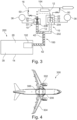
- Fig. 4 schematically shows an example of an aircraft 300 comprising an example of the supply system 200.
- the aircraft 300 comprises a propulsion system 302, an airframe 304, a fuel storage space 306 and a supply system 200 according to one of previous examples and options.
- the airframe 304 is attached to the aircraft 300 and the propulsion system 302 is attached to the airframe 304 and both are configured to levitate and/or accelerate the aircraft 300 on a mission.
- the supply system 200 is configured to be located in the fuel storage space 306 and stores fuel inside the aircraft 300 and the supply system 200 is configured to supply the propulsion system 302 with fuel on the mission.
- the propulsion system 302 is based on hydrogen as propellant.
- the fuel storage space is configured to store hydrogen tanks, respectively storage units storing hydrogen.
- Fig. 5 shows basic steps of an example of a method 400 for clearing leaked fluid 32 from a supply system 200.
- the method 400 comprises the following steps:
- connection device 10 In an example of the method, not shown in Fig. 5 , a leaking site of a fuel system is retrofitted with the connection device 10.
Landscapes
- Engineering & Computer Science (AREA)
- Aviation & Aerospace Engineering (AREA)
- Mechanical Engineering (AREA)
- General Engineering & Computer Science (AREA)
- Filling Or Discharging Of Gas Storage Vessels (AREA)
Abstract
Description
- The present invention relates to providing a passing of supply lines of a storing unit onboard a vehicle; more specifically, the inventions relates to a connection device, to a connection arrangement, to a supply system, to an aircraft comprising the supply system and to a method for clearing leaked fluid from a supply system.
- Storing units such as fuel tanks onboard a vehicle like an aircraft may be equipped with sensing device or other components which may require a wiring or other supply line connection from inside the storing unit to the outside of the storing unit. A sealing barrier may be provided through which the supply lines pass. As an example, in case of storing pressurized fluids, the barrier, and the supply lines passing through, need to fulfil high-pressure sealing criteria. As another example, in case of storing fluids with large diffusivity characteristics, the barrier, and the supply lines passing through, need to show a high leak-tightness. However, it has been shown that additional complex measures like ventilation of storage areas may be needed in case of leakage.
- There may thus be a need for improving the guidance of supply lines from a storing unit.
- The object of the present invention is solved by the subject-matter of the independent claims; further embodiments are incorporated in the dependent claims. It should be noted that the following described aspects of the invention apply also for the connection device, for the supply system, for the aircraft and for the method.
- According to the present invention, a connection device for passing supply lines from a storing unit to an environment of the storing unit is provided. The device comprises a retainer volume encapsulated by an enclosure, a first feedthrough and a second feedthrough. The first feedthrough is arranged attached to the enclosure and is configured to sealingly pass supply lines from an inner lumen of the storing unit to the retainer volume. The second feedthrough is arranged attached to the enclosure and is configured to sealingly pass the supply lines from the retainer volume to the environment of the storing unit. The first feedthrough, the second feedthrough and the enclosure are configured to be leak-tight for a fluid stored in the storing unit. The retainer volume is configured to capture fluid leaking through the first feedthrough and to prevent leaked fluid to reach the environment of the storing unit.
- As an advantage, a secondary barrier is presented by the connection device that will prevent explosive atmosphere creation outside the storage unit e.g. in case of a leakage of the first barrier, i.e. the first feedthrough. The capturing in the retainer volume and thus avoiding the mixture with environmental air prevents that an explosive atmosphere is provided.
- As an advantage, a cable feedthrough with a higher redundancy with respect to leakage is yielded. Overall a more leak-tight cable feedthrough is yielded.
- As an effect, explosive aggregations of fluid in the environment of the storing unit are mitigated.
- This also allows a more secure cable feedthrough.
- According to an example, the retainer volume is configured to provide an inert fluid. The inert fluid is configured to mix with the leaked fluid to yield a non-explosive fluid mixture.
- According to an example, the enclosure is configured to be connected to a sensor for detecting if leaked fluid is present inside the retainer volume.
- According to an example, the enclosure is configured to be connected to a valve arrangement configured to vent the retainer volume.
- According to the present invention, also a connection arrangement for passing supply lines from a storing unit is provided. The arrangement comprises at least one supply line conduit, at least one supply line and a connection device according to one of the previous examples. The at least one supply line conduit is configured to be connected to a storing unit and to guide the at least one supply line from the inner lumen of the storing unit to the connection device. The at least one supply line extends within the at least one supply line conduit through the first feedthrough into the retainer volume and from the retainer volume through the second feedthrough to the environment.
- According to the present invention, also a supply system is provided. The supply system comprises a storing unit storing a fluid in an inner lumen and a connection arrangement according to one of the previous examples. The connection arrangement is connected to the inner lumen of the storing unit via the first feedthrough. The connection arrangement is configured to pass the supply lines from the inner lumen of the storing unit to the environment of the storing unit without leaked fluid from the storing unit.
- As an advantage, a more controllable storing unit is established.
- According to the present invention, also an aircraft is provided. The aircraft comprises a propulsion system, an airframe, a fuel storage space and a supply system according to the previous example. The airframe is attached to the aircraft and the propulsion system is attached to the airframe and both are configured to levitate and/or accelerate the aircraft on a mission. The supply system is configured to be located in the fuel storage space and stores fuel inside the aircraft. The supply system is configured to supply the propulsion system with fuel on the mission. In an option, alternatively or in addition, the supply system is configured to supply other systems used during operation of the aircraft, such as a power supply for aviation systems or onboard entertainment.
- As an advantage, a more controllable aircraft is yielded.
- According to the present invention, also a method for clearing leaked fluid from a supply system is provided. The method comprises the following steps:
- Providing a supply system according to one of the previous examples;
- Attaching a sensor to an enclosure of the supply system;
- Providing fluid to the supply system;
- Operating the sensor while operating the supply system;
- Detecting leaked fluid inside the retainer volume by the sensor;
- Capturing the leaked fluid from a first feedthrough by the enclosure;
- Mixing the leaked fluid with inert fluid in the enclosure to yield a non-explosive fluid; and
- Releasing the non-explosive fluid from the enclosure.
- According to an aspect, a connection device, or a cable supply is connected to a tank storing a fuel. The supply is connected via its first entry to the tank. The first entry is forming a first b blockage between the fuel and an environment of the tank. In case the first entry is leaking, and the first blockage is broken, the supply acts as retention basin and the fuel streams into the supply. A second entry of the supply closes the retention basin and forms a second blockage and the fuel does not contact or mix with the environment of the tank.
- According to an aspect, the connection device presents a first barrier plus a secondary barrier that will prevent explosive atmosphere creation and an enclosed volume between the two barriers. It also allows a detection of first barrier failure and activates safety switches and safely vent the mixture.
- According to an aspect, an enclosure forms a secondary diffusion barrier around an access point to a storing unit. Sites that are used to surveil a storing unit are thus provided with an improved safety for operation the storing unit.
- These and other aspects of the present invention will become apparent from and be elucidated with reference to the embodiments described hereinafter.
- Exemplary embodiments of the invention will be described in the following with reference to the following drawings:
-
Fig. 1 schematically shows a cross-section of an example of a connection device. -
Fig. 2 schematically shows a more detailed cross-section of an example of a connection device. -
Fig. 3 schematically shows a cross-section of an example of a connection arrangement and a supply system. -
Fig. 4 schematically shows an example of an aircraft comprising the supply system. -
Fig. 5 shows basic steps of an example of a method for clearing leaked fluid from a supply system. - Certain embodiments will now be described in greater details with reference to the accompanying drawings. In the following description, like drawing reference numerals are used for like elements, even in different drawings. The matters defined in the description, such as detailed construction and elements, are provided to assist in a comprehensive understanding of the exemplary embodiments. Also, well-known functions or constructions are not described in detail since they would obscure the embodiments with unnecessary detail. Moreover, expressions such as "at least one of', when preceding a list of elements, modify the entire list of elements and do not modify the individual elements of the list.
-
Fig. 1 schematically shows a cross-section of a general example of aconnection device 10 for passingsupply lines 12 from a storingunit 14 to anenvironment 16 of the storingunit 14. Theconnection device 10 comprises aretainer volume 18 encapsulated by anenclosure 20, afirst feedthrough 22 and asecond feedthrough 24. Thefirst feedthrough 22 is arranged attached to theenclosure 20 and is configured to sealinglypass supply lines 12 from aninner lumen 26 of the storingunit 14 to theretainer volume 18. Thesecond feedthrough 24 is arranged attached to theenclosure 20 and is configured to sealingly pass thesupply lines 12 from theretainer volume 18 to anenvironment 16 of the storingunit 14. Thefirst feedthrough 22, thesecond feedthrough 24 and theenclosure 20 are configured to be leak-tight (arrows 28 for a fluid 30 stored in the storingunit 14. Theretainer volume 18 is configured to capture fluid leaking through thefirst feedthrough 22 and to prevent the leakedfluid 32 to reach theenvironment 16 of the storingunit 14. - It is noted that the
supply lines 12 and the storingunit 14 as well as theenvironment 16 are shown for better explanation. In an option, they are not part of theconnection device 10 itself. - The term "connection device" refers to a connector, a transition or an adapter for guiding the supply lines out of a storing unit, respectively into a storing unit.
- The term "passing" refers to any word describing a transit between two separate spaces.
- The term "supply line" refers to a cable, a conduit, a pipe, a wire, a waveguide, or a tube.
- In an example, the
supply line 12 ofFig. 1 is an object that is capable of transporting energetical, structural or material differences between two separate spaces, volumes or phases in a predefined direction. - The term "storing unit" refers to a tank, a vessel, a container, a cistern or a basin. In an example, the storing
unit 14 ofFig. 1 can also be a tube or a pipe or a piping system. - The storing
unit 14 also can be referred to as storage unit. - In an example, the storing
unit 14 is configured to store and transport a volume. The storingunit 14 possesses an encased volume, aninner lumen 26 respectively, that is capable of storing the volume. The storingunit 14 is configured to separate and isolate the volume from the outer surroundings of the storingunit 14 inFig. 1 . - In an example, the storing
unit 14 is configured to supply the stored volume to a given purpose, not shown in detail inFig. 1 . - In an example, the storing
unit 14 is configured to be an integral part of the machinery or a structural part of a vehicle, such as an aircraft or a car, not further shown inFig. 1 . - The term "environment" refers to the surrounding of the storing
unit 14 in its closer periphery or proximity. Theterm environment 16 refers to the surroundings of the storingunit 14 inside the vehicle, such as theinternal environment 16 of the vehicle, whereas the outside of the vehicle can be referred to asexternal environment 16. Theenvironment 16 refers to the inside spacing of the vehicle that bears the storingunit 14. - The term "enclosure" refers to a chamber, an envelope, a compartment, a room, a balloon, a void, a bubble, or a box according to several options of
Fig. 1 . - The
enclosure 20 can also be referred to as retainer. - In an example, the
enclosure 20 can be made from any material that is configured to be gas leak-tight and pressure-proven, e.g. a metal. - In an example, the connection of the
enclosure 20 to the feedthroughs is configured to be gas leak-tight, e.g. for hydrogen gas. - In an example, the position of the feedthroughs can be added to any point of the surface of the
enclosure 20 ofFig. 1 . - In an example, there are more than two feedthroughs, for example three or four feedthroughs, arranged at the
enclosure 20. - In an example, the
enclosure 20 is thermally insulated. - In an example, the
retainer volume 18 is configured to be expendable. - The term "encapsulated" refers to isolating or separating a volume from another volume or dividing volumes, without providing any contact between the volumes.
- The term "retainer volume" refers to any space or lumen that is capable of taking up a volume or a fluid 30. The
retainer volume 18 can also be referred to as retention basin, buffer volume or basin. - In an example, the pressure in the
retainer volume 18 is lower than in the storingunit 14. - The term "feedthrough" refers to a clearance hole, a through boring, a via hole or a cable bushing that is able to conduct a
supply line 12 between to separate volumes, such that the separated volumes do not contact each other. - The term "sealingly pass" refers to the afore mentioned way of passing, guiding, leading, transiting, traversing or conducting a
supply line 12 through the feedthrough. - In an example, sealingly passing implies that a fluid on one side of the feedthrough cannot creep or permeate along the interface between the boring and the
supply line 12 in the feedthrough to arrive at the other side of the feedthrough inFig. 1 . Thesupply lines 12 are sealed in the feedthrough with the feedthrough to form a unity impermeable to any fluid 30. The feedthrough becomes a physical barrier except for the supply lines 12. - In an example, sealingly passing the
supply lines 12 through the feedthrough is realized by clamping thesupply lines 12 tightly together by the feedthrough, such that no other volume than thesupply lines 12 can pass the feedthrough. This volume also includes the substances conducted by the supply lines 12. - In an example, sealingly passing the
supply lines 12 through the feedthrough can be realized by fusing an insulation of thesupply lines 12 or fusing thesupply lines 12 with the feedthrough. The supply lines themselves pass and reach through a physical barrier. - In an example, sealingly passing the
supply lines 12 through the feedthrough can be realized by providing supply line connectors on both sides of the feedthrough, the feedthrough being a physical barrier without any cable boring. The supply line connectors are connected in the feedthrough, enclosed in a leak-tight matrix and provide signal transmission between thesupply lines 12 connected to the supply line connectors on either side of the feedthrough. The supply line connectors are referred to as pins. The supply line connectors pass and reach through a physical barrier, but not the supply lines themselves. - In an example, the feedthroughs sealingly passing a
supply line 12 provide a barrier against hydrogen gas. - In an example, a feedthrough is provided by contactless connection of two supplies through a separating object.
- In an example, the feedthroughs are configured to sustain and withstand cryogenic temperatures.
- In an example, the feedthroughs are configured to be resistant against temperature-induced movement.
- In an example, the feedthrough acts as a cable boring with a gasket or tightening for the cable.
- The term "inner lumen" can also be referred to as inside, interior, or cavity. The term "leak" refers to a channel, a fracture, a bore, a recess in an object that permits exchange of two environments separated by the object. The term "leaking" refers to the exchange of the two environments, either in the direction of one of the environments or between both environments. The leaks are not depicted in
Fig. 1 . - The term "leak-tight" refers to a condition, e.g., of a form fit bounding between to objects or the object itself, separating two environments. The condition minimizes the contact of the outside and the inside of the bounding with the separated environments.
- The term "fluid" refers to e.g. a liquid or a gas that continuously deforms, i.e., flows, under an applied shear stress, or external force.
- The fluid 30 stored in the storing
unit 14 ofFig. 1 can also be referred to as fuel. - In an example, the fluid 30 can be any substance carrying a form of energy, i.e. a fuel. In an example, the storing
unit 14 is configured to store a fuel. In an example, the storingunit 14 is configured to store hydrogen in liquid and gaseous form. In an example, the storingunit 14 is configured to store hydrogen containing substances. In an example, the storingunit 14 is configured to store cryogenic fluid or fluid under high pressure. - In an example, the storing
unit 14 comprises an inner tank and an outer tank, not shown inFig. 1 . The inner tank is configured to store the liquid and the outer tank is configured to insulate the inner tank from theenvironment 16. - In an example, two types of connections are provided.
- In an example, the connection device of
Fig. 1 , having a plurality of cables, uses two feedthroughs. An example for the feedthroughs are the so-called ATEX feedthroughs (French: ATmosphères Explosives). The connection with two feedthroughs is designed as such that the first ATEX feedthrough is connected (via the retainer volume) to the second ATEX feedthrough which in turn is connected to the data acquisition center. Thefirst feedthrough 22 acts as a barrier between the hydrogen filled storage unit, e.g., a pipe and the enclosure, e.g. a box, or chamber, filled with, e.g. inert gas, i.e. an inert gas box. In case of a leakage of thefirst feedthrough 22, the leaking hydrogen will mix with inert gas, e.g. helium, and the creation of an explosive mixture is avoided. - In further examples, other types of an inert fluid, e.g. another inert gas, are provided. The inert gas can be chosen according to the temperature, or expected temperature range, of the leaking gas such as leaking hydrogen at the first feedthrough. If the temperature of the leaking gas is low, the inert gas is provided such that it preferably stays in its gaseous state to better mix with the leaking gas. Helium can be used, e.g. for hydrogen leakage, since helium does not liquify at the expected LH2 temperatures.
- The term "LH2" or "IH2" refers to liquid hydrogen.
- In an example, an inert gas with a lower boiling point than hydrogen is chosen, to ensure proper mixing of the inert gas with the leaking gas to yield a non-explosive gas mixture.
- In another example, a preheated inert gas is mixed with the leaking gas.
- The
second feedthrough 24 acts as a barrier between the inert gas filled box and the ambient environment. In case of the leakage of thesecond feedthrough 24, the first barrier will serve as a means of protection of air, e.g. oxygen going in the hydrogen pipe and from creation of an explosive mixture. - In an example, the connection device is a double barrier electrical feedthrough connection to a liquid hydrogen inner tank. It can be used to safely connect sensors placed inside the inner tank to electrical source or data acquisition systems in the ambient environment, i.e. outside the inner tank. It presents a secondary barrier that will prevent explosive atmosphere creation. It also allows a detection of first barrier failure and activate safety switches and safely vent the mixture.
-
Fig. 2 schematically shows a more detailed cross-section of an example of aconnection device 10. Theretainer volume 18 ofFig. 2 is configured to provide aninert fluid 34. Theinert fluid 34 is configured to mix with the leakedfluid 32 to yield anon-explosive fluid mixture 36. - The term "inert" can be referred to as unreactive.
- In an example, the
environment 16 of the storingunit 14 inFig. 2 comprises fluids that react vigorously with the fluid 30 from the storingunit 14 under sudden release of energy, causing explosions. Theinert fluid 34 in theenclosure 20 prevents fluids from theenvironment 16 to enter theenclosure 20 and prevents fluid 30 from the storingunit 14 to enter theenclosure 20. Theinert fluid 34 prevents fluids from theenvironment 16 to mix withfluids 30 from the storingunit 14. - In an example, the
inert fluid 34 mixes with fluid 30 from the storingunit 14 in theenclosure 20 and the fluid mix, e.g. thenon-explosive fluid mixture 36 inFig. 2 is thereafter removed from theenclosure 20. - In an example, the fluid of the
environment 16 is the atmosphere and the atmosphere comprises oxygen. Theinert fluid 34 hampers the oxygen of the atmosphere to react with the fluid 30 from the storingunit 14, i.e. hydrogen, to prevent explosions. - In an example, the inert gas in the
enclosure 20 ofFig. 2 can be regarded as protective gas insulation. The protective gas insulation hampers the diffusion of fluid into theenvironment 16 of the storingunit 14. - In an example, the
inert fluid 34 is provided inside theretainer volume 18 and the inert gas is configured to mix with the leakedfluid 32 to yield anon-explosive fluid mixture 36 inFig. 2 . - In an example, the
inert fluid 34 is a protection gas. The gas comprises one of the group of: nitrogen, helium, argon, krypton. - In an example, the
inert fluid 34 is in a liquid state or is a liquid substance at standard conditions. - In another example, the
inert fluid 34 is a liquid or a solid substance capable of adsorbing or reacting with the fluid 30 from the storingunit 14 inFig. 2 . - In an example, the
retainer volume 18 or theenclosure 20 are configured with devices or a certain shape to maximize the mixing of theinert fluid 34 and the leakedfluid 32, not shown inFig. 2 . - In an example, the pressure of the fluid in the storing
unit 14 is higher, than the pressure of theinert fluid 34 in theretainer volume 18. - In an example, the pressure of the
inert fluid 34 in theenclosure 20 is lower than atmospheric pressure. - In an example, the
enclosure 20 is configured to be suppliable by an external source ofinert fluid 34. - In an example, the
connection device 10 can be regarded as inert gas-protected feedthrough. - As an advantage, continuously permeating fluid from the feedthrough at the storing
unit 14 can be removed safely by aninert fluid 34 without creating an explosive atmosphere. - As an advantage, the amount of continuously permeating fluid from the feedthrough at the storing
unit 14 can be kept below the explosive levels. - In an example of
Fig. 2 , the enclosure is configured to be connected to asensor 38 for detecting if leakedfluid 32 is present inside theretainer volume 18. - In an example, the
sensor 38 is a hydrogen sensor. - In an example, the
sensor 38 is an oxygen sensor. - In an example, the enclosure is configured to connect more than one
sensor 38, i.e. configured to connect a hydrogen sensor and a oxygen sensor. - In an example, hydrogen and oxygen sensors are provided, which are connected to the enclosure, i.e., the inert gas box. The inert gas boxes are welded on the storage unit, e.g. pipes, at the bottom. In case of hydrogen or oxygen leak, the sensors will declare an alarm and e.g. a safety procedure on an aircraft, related to this situation will be followed. For example, tank filling will be stopped, and hydrogen safe extraction can be provided once the airplane is on ground before maintenance on the malfunctioning feedthrough. The mixture of hydrogen and nitrogen can be safely evacuated through the valves which are equipped with non return valves, preventing back flow of air in case of valve spurious opening.
- In an example, the
valve arrangement 50 ofFig. 2 is an automatic valve arrangement and connected to a controlling unit. Thesensor 38 is configured to generate a signal that can be transmitted to the controlling unit of the valve arrangement in order to operate the valve arrangement. - As an advantage a detection of first barrier failure, activation of safety switches and safely venting of the mixture is allowed.
- In an example of
Fig. 2 , the enclosure comprises aconnection 40 for sealingly attaching asupply line conduit 42 guiding thesupply lines 12 from the storingunit 14 to theconnection device 10. Thefirst feedthrough 22 is provided at anend 44 of the supply line conduit. Thefirst feedthrough 22 provides abarrier 46 between aninner volume 48 of thesupply line conduit 42 and theretainer volume 18. - In an example, the enclosure of the
connection device 10 inFig. 2 also encloses the connection of thefirst feedthrough 22 to the storingunit 14, such that leakedfluid 32, that permeates through the connection of thefirst feedthrough 22 and the storingunit 14 is taken up by the enclosure. - In an option of the example not shown in
Fig. 2 , at least one of thefirst feedthrough 22 and thesecond feedthrough 24 is an ATEX feedthrough. - In an example, the feedthroughs are configured that they prevent the contact between a fluid 30 and their
supply lines 12. The feedthroughs isolate thesupply lines 12 from the fluid 30. - In an example, Spectite (trademark) feedthroughs are deployed.
- In an example of
Fig. 2 , the enclosure is configured to be connected to avalve arrangement 50 configured to vent theretainer volume 18. - In an example, an automatic valve arrangement is connected to the enclosure.
- In an example, the automatic valve arrangement is configured to be operated remotely.
- In an example, in case of the
connection device 10 ofFig. 2 being aboard an aircraft, thevalve arrangement 50 is connected with its exhaust pipe to theexternal environment 16 of the aircraft, which is not shown inFig. 2 . - In an example, the
valve arrangement 50 is configured to be connected to a controller unit and the venting of theretainer volume 18 can be automatized or made dependent on other parameters of the system the controller unit is connected to. - As an advantage, remote operation of the
valve arrangement 50 increases safety of theconnection device 10. - In an example of
Fig. 2 , the enclosure is configured to be connected to a valve arrangement that prevents a flow-back (arrow 52 inFig. 2 ) of anenvironmental fluid 54 into theretainer volume 18. - In an example, the valve arrangement that prevents a flow-back of an
environmental fluid 54 is configured to prevent oxygen from entering the enclosure through thevalve arrangement 54. -
Fig. 3 schematically shows a cross-section of an example of aconnection arrangement 100 for passingsupply lines 12 from a storingunit 14. Theconnection arrangement 100 comprises at least onesupply line conduit 42, at least onesupply line 12 and an example of theconnection device 10 according to one of the previous examples. The at least onesupply line conduit 42 is configured to be connected to the storingunit 14 and to guide the at least onesupply line 12 from theinner lumen 26 of the storingunit 14 to theconnection device 10. The at least onesupply line 12 extends within the at least onesupply line conduit 42 through thefirst feedthrough 22 into theretainer volume 18 and from theretainer volume 18 through thesecond feedthrough 24 to theenvironment 16. - In an example, the storing
unit 14 comprises an inner and an outer tank, not shown inFig. 3 for reasons of simplicity. Theconnection device 10 is located at the outer tank and a connection between the inner tank and theconnection device 10 is provided by thesupply line conduit 42 that traverses the outer tank. - In an example, the
connection device 10 is connected to thesupply line conduit 42 by welding. - In an example not shown in
Fig. 3 , thesupply lines 12 are provided as at least one of the group of cables for transmitting electrical signals, cables for transmitting electrical power, optical guides for transmitting optical signals, thermal guides for transmitting thermal signals and pipes for transporting substances between aninner lumen 26 of the storingunit 14 and theenvironment 16. - In an example, the
supply lines 12 are leak-tight and configured to prevent leaking of the fluid 30 inside thesupply lines 12 and along thesupply lines 12, such that thesupply lines 12 prevent the transport of the leakedfluid 32 along thesupply lines 12, not shown inFig. 3 . - In an example, the supply lines are configured for transmitting electrical signals and electrical power as well.
- In an example, the optical guides are glass fibers.
- In an example, the thermal guides are thermo-couples.
- In an example, the pipes conduct
inert fluid 34 into the storingunit 14 to clean the storingunit 14 from the stored fluid, also not shown inFig. 3 . - In an option of the example of
Fig. 3 , theconnection arrangement 100 further comprises aninner unit 102 and anouter unit 104. Theinner unit 102 is connected to the at least onesupply line 12. Theouter unit 104 is also connected to the at least onesupply line 12. Theinner unit 102 comprises at least one of the group of: sensing unit and heating element. The outer unit comprises at least one of the group of: data acquisition unit and electrical power source. The outer unit is configured to retrieve signals from and/ or supply power to the inner unit in the inner lumen of the storing unit. - The term "data acquisition unit" can also be referred to as "data acquisition center".
- In an example, the
inner unit 102 is a sensing element configured to provide sensing within the storing unit. Theouter unit 104 is a data acquisition unit configured to receive and process the sensed data. - In an example, the
inner unit 102 is a heating element configured to provide heating to a part of the fluid stored in the storing unit. Theouter unit 104 is an electrical power source to supply the heating source with electric energy. - In an example, the
inner unit 102 comprises a sensing element as well as a heating element. Theouter unit 104 comprises a data acquisition unit as well as an electrical power source. - In an example, a double barrier feedthrough system for LH2 vessels, e.g. the storing
unit 14 inFig. 3 , with electrical sensors inside is provided. Sensors placed inside the inner tank of the LH2 vessels are connected to the acquisition and control systems placed outside in theambient environment 16. - In an example, the aim of the
connection device 10 is to connect sensors or a heating element inside a liquid hydrogen tank, e.g. the storingunit 14 inFig. 3 , to a data acquisition and control system, or for example an electrical power source, while preventing the creation of an explosive atmosphere in case of failure of one barrier. - As an advantage, a safe and protected surveillance is provided.
-
Fig. 3 also schematically shows a cross-section of asupply system 200. Thesupply system 200 comprises a storingunit 14 storing a fluid 30 in aninner lumen 26 and an example of theconnection arrangement 100 according to one of the previous examples and options. Theconnection arrangement 100 is connected to theinner lumen 26 of the storingunit 14 via thefirst feedthrough 22. Theconnection arrangement 100 is configured to pass thesupply lines 12 from theinner lumen 26 of the storingunit 14 to theenvironment 16 of the storingunit 14 without leaked fluid 32 from the storingunit 14. - In an example, the storing
unit 14 stores hydrogen in liquid or fluid state. - In an option of the example of
Fig. 3 , theinner lumen 26 of the storingunit 14 comprisescoaxial cables 202. Atransition 204 is provided between thecoaxial cables 202 and thesupply lines 12 of thesupply system 200. Thetransition 204 is configured to transmit signals of thecoaxial cable 202 to the supply lines 12. Thetransition 204 is configured such that the signals of thecoaxial cable 202 pass thefirst feedthrough 22 by the supply lines 12. - In an example, the
supply system 200 comprising thecoaxial cables 202 represents a second type of connection inFig. 3 . It possesses a first connection between a sensor inside the tank, for example a capacitive gauge, to a non-ATEX connector, which is connected to a first ATEX feedthrough, the latter being directly connected to a second ATEX feedthrough which in turn is connected to the data acquisition center. The retainer volume is provided between the first and the second ATEX connector. - The main difference between the first type, shown at the left side of
Fig. 3 and second type, shown at the right side ofFig. 3 , is the fact that the second type needs to be first connected to a non-ATEX connector in order to be connected to an ATEX feedthrough, because the cables may comprisecoaxial cables 202 or triaxial cables. The same protection applies to the second type as in that thefirst feedthrough 22 acts as a barrier between the hydrogen filled pipe, i.e. thesupply line conduit 42, and an inert gas filled box (chamber), i.e. the enclosure. In case of the failure of thefirst feedthrough 22, the leaking hydrogen will only mix with inert gas, e.g. nitrogen, and won't be able to create an explosive mixture. Thesecond feedthrough 24 acts as a barrier between the inert gas filled box and the ambient environment. In case of the failure of thesecond feedthrough 24, the first barrier will serve as a means of protection of air, e.g. oxygen, going in the hydrogen pipe and from creation of explosive mixture. - In an example, the transition is a multipin feedthrough and the supply lines comprise the pins of the multipin feedthrough.
- In an example, at least one of the
first feedthrough 22 and thesecond feedthrough 24 is a multipin feedthrough. - In an example, the coaxial cable is insulated with respect to fluid leaking into the dielectric material of the coaxial cable. As an advantage,
coaxial cables 202 can be used in surveillance of the storingunit 14. As a further advantage, more delicate measurements of the storingunit 14 inFig. 3 can be executed. - In an example of
Fig. 3 , a part of theinner lumen 26 of the storing tank forms thesupply line conduit 42 with adistal end opening 206. Thesupply line conduit 42 is configured to enclose the supply lines 12. Theconnection device 10 is configured to connect to thedistal end opening 206 and pass thesupply lines 12 from theinner lumen 26 of the storing tank via thesupply line conduit 42 to theenvironment 16 of thesupply system 200. - In an example, the
supply line conduit 42 is insulated from cryogenic temperatures of the inner tank by the outer tank, not shown inFig. 3 . - In an example, the
distal end opening 206 is in a distance to the inner tank that transfer of the cryogenic temperatures of the inner tank to theconnection device 10 is mitigated. - In an example, the
supply line conduit 42 is configured to insulate thesupply system 200 from the temperatures of the fluid 30. - In an example, the
supply line conduit 42 is enclosed by an insulation of an outer tank, not shown inFig. 3 . - As an advantage, the
connection device 10 is not exposed to the temperature gradient at the storingunit 14. -
Fig. 4 schematically shows an example of anaircraft 300 comprising an example of thesupply system 200. Theaircraft 300 comprises apropulsion system 302, anairframe 304, afuel storage space 306 and asupply system 200 according to one of previous examples and options. Theairframe 304 is attached to theaircraft 300 and thepropulsion system 302 is attached to theairframe 304 and both are configured to levitate and/or accelerate theaircraft 300 on a mission. Thesupply system 200 is configured to be located in thefuel storage space 306 and stores fuel inside theaircraft 300 and thesupply system 200 is configured to supply thepropulsion system 302 with fuel on the mission. - In an example, the
propulsion system 302 is based on hydrogen as propellant. - In an example, the fuel storage space is configured to store hydrogen tanks, respectively storage units storing hydrogen.
-
Fig. 5 shows basic steps of an example of amethod 400 for clearing leaked fluid 32 from asupply system 200. Themethod 400 comprises the following steps: - In a
first step 402, asupply system 200 according to one of the previous examples and options is provided. - In a
second step 404, asensor 38 is attached to anenclosure 20 of thesupply system 200. - In a
third step 406, fluid 30 is supplied to thesupply system 200. - In a
fourth step 408, thesensor 38 is operated while operating thesupply system 200. - In a
fifth step 410, leakedfluid 32 inside theretainer volume 18 is detected by thesensor 38. - In a
sixth step 412, the leaked fluid 32 from afirst feedthrough 22 is captured by theenclosure 20. - In a
seventh step 414, the leakedfluid 32 is mixed withinert fluid 34 in theenclosure 20 to yield a non-explosive fluid. - In an
eighth step 416, the non-explosive fluid is released from theenclosure 20. - In an example of the method, not shown in
Fig. 5 , a leaking site of a fuel system is retrofitted with theconnection device 10. - While the invention has been illustrated and described in detail in the drawings and foregoing description, such illustration and description are to be considered illustrative or exemplary and not restrictive. The invention is not limited to the disclosed embodiments. Other variations to the disclosed embodiments can be understood and effected by those skilled in the art in practicing a claimed invention, from a study of the drawings, the disclosure, and the dependent claims.
- In the claims, the word "comprising" does not exclude other elements or steps, and the indefinite article "a" or "an" does not exclude a plurality. A single processor or other unit may fulfil the functions of several items re-cited in the claims. The mere fact that certain measures are re-cited in mutually different dependent claims does not indicate that a combination of these measures cannot be used to advantage. Any reference signs in the claims should not be construed as limiting the scope.
Claims (15)
- A connection device (10) for passing supply lines (12) from a storing unit (14) to an environment (16) of the storing unit, the device comprising:- a retainer volume (18) encapsulated by an enclosure (20);- a first feedthrough (22); and- a second feedthrough (24);wherein the first feedthrough is arranged attached to the enclosure and is configured to sealingly pass supply lines from an inner lumen (26) of the storing unit to the retainer volume;wherein the second feedthrough is arranged attached to the enclosure and is configured to sealingly pass the supply lines from the retainer volume to the environment of the storing unit;wherein the first feedthrough, the second feedthrough and the enclosure are configured to be leak-tight for a fluid (30) stored in the storing unit; andwherein the retainer volume is configured to capture fluid leaking through the first feedthrough and to prevent leaked fluid (32) to reach the environment of the storing unit.
- Device according to claim 1, wherein the retainer volume is configured to provide an inert fluid (34); and wherein the inert fluid is configured to mix with the leaked fluid to yield a non-explosive fluid mixture (36).
- Device according to one claim 1 or 2, wherein the enclosure is configured to be connected to a sensor (38) for detecting if leaked fluid is present inside the retainer volume.
- Device according to claim 1, 2 or 3, wherein the enclosure comprises a connection (40) for sealingly attaching a supply line conduit (42) guiding the supply lines from the storing unit to the connection device;
wherein the first feedthrough is provided at an end (44) of the supply line conduit, the first feedthrough providing a barrier (46) between an inner volume (48) of the supply line conduit and the retainer volume. - Device according to one of the preceding claims, wherein at least one of the first feedthrough and the second feedthrough is an ATEX feedthrough.
- Device according to one of the preceding claims, wherein the enclosure is configured to be connected to a valve arrangement (50) configured to vent the retainer volume.
- Device according to one of the preceding claims, wherein the enclosure is configured to be connected to a valve arrangement that prevents a flow-back of an environmental fluid (54) into the retainer volume.
- A connection arrangement (100) for passing supply lines from a storing unit, the arrangement comprising:- at least one supply line conduit (42);- at least one supply line (12); and- a connection device (10) according to one of the preceding claims;wherein the at least one supply line conduit is configured to be connected to the storing unit and to guide the at least one supply line from the inner lumen of the storing unit to the connection device; andwherein the at least one supply line extends within the at least one supply line conduit through the first feedthrough into the retainer volume and from the retainer volume through the second feedthrough to the environment.
- Arrangement according to claim 8, wherein the supply lines are provided as at least one of the group of:i) cables for transmitting electrical signals;ii) cables for transmitting electrical power;iii) optical guides for transmitting optical signals;iv) thermal guides for transmitting thermal signals; andv) pipes for transporting substances between an inner lumen of the storing unit and the environment.
- Arrangement according to claim 8 or 9, wherein the connection arrangement further comprises:- an inner unit (102); and- an outer unit (104);wherein the inner unit and the outer unit are both connected to the at least one supply line;wherein the inner unit comprises at least one of the group of: sensing unit and heating element; andwherein the outer unit comprises at least one of the group of: data acquisition unit and electrical power source.
- A supply system (200), comprising:- a storing unit storing a fluid in an inner lumen; and- a connection arrangement according to one of claims 8 to 10;wherein the connection arrangement is connected to the inner lumen of the storing unit via the first feedthrough; andwherein the connection arrangement is configured to pass the supply lines from the inner lumen of the storing unit to the environment of the storing unit without leaked fluid from the storing unit.
- System according to claim 11, wherein the inner lumen of the storing unit comprises coaxial cables (202);wherein a transition (204) is provided between the coaxial cables and the supply lines of the supply system;wherein the transition is configured to transmit signals of the coaxial cable to the supply lines; andwherein the transition is configured such that the signals of the coaxial cable pass the first feedthrough by the supply lines.
- System according to claim 11 or 12, wherein a part of the inner lumen of the storing tank forms the supply line conduit with a distal end opening (206);wherein the supply line conduit is configured to enclose the supply lines; andwherein the connection device is configured to connect to the distal end opening and pass the supply lines from the inner lumen of the storing tank via the supply line conduit to the environment of the supply system.
- An aircraft (300), comprising:- a propulsion system (302);- an airframe (304);- a fuel storage space (306); and- a supply system according to one of claims 11 to 13wherein the airframe is attached to the aircraft and the propulsion system is attached to the airframe and both are configured to levitate and/or accelerate the aircraft on a mission;wherein the supply system is configured to be located in the fuel storage space and stores fuel inside the aircraft; andwherein the supply system is configured to supply the propulsion system with fuel on the mission.
- A method (400) for clearing leaked fluid from a supply system:- Providing (402) a supply system according to one of the claims 11 to 13;- Attaching (404) a sensor to an enclosure of the supply system;- Providing (406) fluid to the supply system;- Operating (408) the sensor while operating the supply system;- Detecting (410) leaked fluid inside the retainer volume by the sensor;- Capturing (412) the leaked fluid from a first feedthrough by the enclosure;- Mixing (414) the leaked fluid with inert fluid in the enclosure to yield a non-explosive fluid; and- Releasing (416) the non-explosive fluid from the enclosure.
Priority Applications (1)
| Application Number | Priority Date | Filing Date | Title |
|---|---|---|---|
| EP23171875.0A EP4458680B1 (en) | 2023-05-05 | 2023-05-05 | Double barrier feedthrough |
Applications Claiming Priority (1)
| Application Number | Priority Date | Filing Date | Title |
|---|---|---|---|
| EP23171875.0A EP4458680B1 (en) | 2023-05-05 | 2023-05-05 | Double barrier feedthrough |
Publications (2)
| Publication Number | Publication Date |
|---|---|
| EP4458680A1 true EP4458680A1 (en) | 2024-11-06 |
| EP4458680B1 EP4458680B1 (en) | 2026-02-11 |
Family
ID=86330159
Family Applications (1)
| Application Number | Title | Priority Date | Filing Date |
|---|---|---|---|
| EP23171875.0A Active EP4458680B1 (en) | 2023-05-05 | 2023-05-05 | Double barrier feedthrough |
Country Status (1)
| Country | Link |
|---|---|
| EP (1) | EP4458680B1 (en) |
Citations (7)
| Publication number | Priority date | Publication date | Assignee | Title |
|---|---|---|---|---|
| DE102010015401A1 (en) * | 2010-04-19 | 2011-10-20 | Linde Aktiengesellschaft | Storage device i.e. gas cylinder, for storing e.g. oxygen in ship and submarine, has connector surrounded by pressurized cap that is attached to discharge line, and valve that is arranged within pressurized cap attached to connector |
| CN207433266U (en) * | 2017-11-09 | 2018-06-01 | 浙江汇润电气有限公司 | Conducting wire, plug wire adapter assembly and fuel tank |
| CN112576929A (en) * | 2020-11-29 | 2021-03-30 | 沪东重机有限公司 | Cable cabin-penetrating sealing device of pressure container |
| CN114060719A (en) * | 2021-11-15 | 2022-02-18 | 皖西学院 | A hydrogen leak detection device for a hydrogen energy bus |
| CN114962988A (en) * | 2022-06-07 | 2022-08-30 | 深圳康纳未来机器人有限公司 | Hydrogen filling equipment capable of detecting hydrogen leakage |
| WO2022234176A1 (en) * | 2021-05-07 | 2022-11-10 | Wärtsilä Finland Oy | Fuel storage and supply system, method of operating such a system and marine vessel |
| EP4129827A1 (en) * | 2021-08-03 | 2023-02-08 | Airbus (S.A.S.) | Aircraft including at least one device for supplying hydrogen and at least one sealed container in which is positioned at least one piece of equipment of said device for supplying hydrogen |
-
2023
- 2023-05-05 EP EP23171875.0A patent/EP4458680B1/en active Active
Patent Citations (7)
| Publication number | Priority date | Publication date | Assignee | Title |
|---|---|---|---|---|
| DE102010015401A1 (en) * | 2010-04-19 | 2011-10-20 | Linde Aktiengesellschaft | Storage device i.e. gas cylinder, for storing e.g. oxygen in ship and submarine, has connector surrounded by pressurized cap that is attached to discharge line, and valve that is arranged within pressurized cap attached to connector |
| CN207433266U (en) * | 2017-11-09 | 2018-06-01 | 浙江汇润电气有限公司 | Conducting wire, plug wire adapter assembly and fuel tank |
| CN112576929A (en) * | 2020-11-29 | 2021-03-30 | 沪东重机有限公司 | Cable cabin-penetrating sealing device of pressure container |
| WO2022234176A1 (en) * | 2021-05-07 | 2022-11-10 | Wärtsilä Finland Oy | Fuel storage and supply system, method of operating such a system and marine vessel |
| EP4129827A1 (en) * | 2021-08-03 | 2023-02-08 | Airbus (S.A.S.) | Aircraft including at least one device for supplying hydrogen and at least one sealed container in which is positioned at least one piece of equipment of said device for supplying hydrogen |
| CN114060719A (en) * | 2021-11-15 | 2022-02-18 | 皖西学院 | A hydrogen leak detection device for a hydrogen energy bus |
| CN114962988A (en) * | 2022-06-07 | 2022-08-30 | 深圳康纳未来机器人有限公司 | Hydrogen filling equipment capable of detecting hydrogen leakage |
Also Published As
| Publication number | Publication date |
|---|---|
| EP4458680B1 (en) | 2026-02-11 |
Similar Documents
| Publication | Publication Date | Title |
|---|---|---|
| US12031686B2 (en) | Device and method for storing and supplying fluid fuel | |
| US20210107674A1 (en) | System and method for the transfer of cryogenic fluids | |
| EP2972189B1 (en) | Gas-line probe adapter for connecting vacuum jacketing | |
| EP4101770B1 (en) | Leak detection for pressurized fluid systems | |
| US6374618B1 (en) | Cryogenic fluid supply from supercritical storage system | |
| CN106170657A (en) | The sealing heat-insulated container being arranged in float structure | |
| EP2505982A2 (en) | Conduit protection system and method | |
| US20100108687A1 (en) | Assembly and system for tank filling, withdrawal and pressure management of a cryogenic liquid | |
| EP3291242B1 (en) | Passively operating cooling device for ex-vessel corium | |
| KR20180138214A (en) | Hydrogen filling station with liquid hydrogen | |
| EP4458680B1 (en) | Double barrier feedthrough | |
| US20090025400A1 (en) | Device and Method for Protecting a Cryogenic Tank and Tank Comprising Such a Device | |
| US20200277036A1 (en) | Mobile container-tank module | |
| AU2016211087A1 (en) | Apparatus for storing and transporting a cryogenic fluid on-board a ship | |
| US20230135912A1 (en) | Optimized connection assembly between two portions of a cryogenic line, comprising a double sealing barrier, a fluid expansion chamber and a detector for detecting the presence of the fluid in said chamber | |
| Higuchi et al. | Development and flight test of metal-lined CFRP cryogenic tank for reusable rocket | |
| WO2008085005A1 (en) | Tank for holding a cryogenic liquid and a conduit assembly, and a system for effecting flow control and pressure management of a cryogenic liquid held in the tank | |
| CN117588679A (en) | Method for fitting the boom to the tank | |
| CN116265802A (en) | Facilities including tanks and dome-like structures for the storage of liquefied gases | |
| RU2737960C1 (en) | System for cryogenic storage and supply of reagents for power plant with electrochemical generators | |
| CN114008376B (en) | Tank for transporting and/or storing liquid gas | |
| US20260036263A1 (en) | Connection space and hydrogen supply arrangement | |
| EP4102205B1 (en) | Leak detection for pressurized fluid systems | |
| US20250229112A1 (en) | In-ground raceway of a safety system associated with a structure with one or more fire rated component(s) to provide physical isolation and to seamlessly and jointlessly transition a metallic coil tube across perpendicular directions | |
| US7836754B1 (en) | Cryogenic feed-through test rig |
Legal Events
| Date | Code | Title | Description |
|---|---|---|---|
| PUAI | Public reference made under article 153(3) epc to a published international application that has entered the european phase |
Free format text: ORIGINAL CODE: 0009012 |
|
| STAA | Information on the status of an ep patent application or granted ep patent |
Free format text: STATUS: THE APPLICATION HAS BEEN PUBLISHED |
|
| AK | Designated contracting states |
Kind code of ref document: A1 Designated state(s): AL AT BE BG CH CY CZ DE DK EE ES FI FR GB GR HR HU IE IS IT LI LT LU LV MC ME MK MT NL NO PL PT RO RS SE SI SK SM TR |
|
| STAA | Information on the status of an ep patent application or granted ep patent |
Free format text: STATUS: REQUEST FOR EXAMINATION WAS MADE |
|
| 17P | Request for examination filed |
Effective date: 20250425 |
|
| GRAP | Despatch of communication of intention to grant a patent |
Free format text: ORIGINAL CODE: EPIDOSNIGR1 |
|
| STAA | Information on the status of an ep patent application or granted ep patent |
Free format text: STATUS: GRANT OF PATENT IS INTENDED |
|
| RIC1 | Information provided on ipc code assigned before grant |
Ipc: B64D 37/00 20060101AFI20251013BHEP Ipc: B64D 37/32 20060101ALI20251013BHEP Ipc: B60K 15/035 20060101ALI20251013BHEP Ipc: F17C 13/12 20060101ALI20251013BHEP Ipc: H01B 17/30 20060101ALI20251013BHEP Ipc: B60K 15/03 20060101ALN20251013BHEP |
|
| RIC1 | Information provided on ipc code assigned before grant |
Ipc: B64D 37/00 20060101AFI20251022BHEP Ipc: B64D 37/32 20060101ALI20251022BHEP Ipc: B60K 15/035 20060101ALI20251022BHEP Ipc: F17C 13/12 20060101ALI20251022BHEP Ipc: H01B 17/30 20060101ALI20251022BHEP Ipc: B60K 15/03 20060101ALN20251022BHEP |
|
| INTG | Intention to grant announced |
Effective date: 20251103 |
|
| GRAS | Grant fee paid |
Free format text: ORIGINAL CODE: EPIDOSNIGR3 |
|
| GRAA | (expected) grant |
Free format text: ORIGINAL CODE: 0009210 |
|
| STAA | Information on the status of an ep patent application or granted ep patent |
Free format text: STATUS: THE PATENT HAS BEEN GRANTED |
|
| AK | Designated contracting states |
Kind code of ref document: B1 Designated state(s): AL AT BE BG CH CY CZ DE DK EE ES FI FR GB GR HR HU IE IS IT LI LT LU LV MC ME MK MT NL NO PL PT RO RS SE SI SK SM TR |
|
| REG | Reference to a national code |
Ref country code: CH Ref legal event code: F10 Free format text: ST27 STATUS EVENT CODE: U-0-0-F10-F00 (AS PROVIDED BY THE NATIONAL OFFICE) Effective date: 20260211 Ref country code: GB Ref legal event code: FG4D |
|
| REG | Reference to a national code |
Ref country code: DE Ref legal event code: R096 Ref document number: 602023011764 Country of ref document: DE |
|
| REG | Reference to a national code |
Ref country code: IE Ref legal event code: FG4D |
|
| REG | Reference to a national code |
Ref country code: NL Ref legal event code: MP Effective date: 20260211 |
|
| PG25 | Lapsed in a contracting state [announced via postgrant information from national office to epo] |
Ref country code: RS Free format text: LAPSE BECAUSE OF FAILURE TO SUBMIT A TRANSLATION OF THE DESCRIPTION OR TO PAY THE FEE WITHIN THE PRESCRIBED TIME-LIMIT Effective date: 20260511 |
|
| PG25 | Lapsed in a contracting state [announced via postgrant information from national office to epo] |
Ref country code: ES Free format text: LAPSE BECAUSE OF FAILURE TO SUBMIT A TRANSLATION OF THE DESCRIPTION OR TO PAY THE FEE WITHIN THE PRESCRIBED TIME-LIMIT Effective date: 20260211 |
|
| PG25 | Lapsed in a contracting state [announced via postgrant information from national office to epo] |
Ref country code: PL Free format text: LAPSE BECAUSE OF FAILURE TO SUBMIT A TRANSLATION OF THE DESCRIPTION OR TO PAY THE FEE WITHIN THE PRESCRIBED TIME-LIMIT Effective date: 20260211 |
|
| PG25 | Lapsed in a contracting state [announced via postgrant information from national office to epo] |
Ref country code: GR Free format text: LAPSE BECAUSE OF FAILURE TO SUBMIT A TRANSLATION OF THE DESCRIPTION OR TO PAY THE FEE WITHIN THE PRESCRIBED TIME-LIMIT Effective date: 20260512 |
|
| REG | Reference to a national code |
Ref country code: LT Ref legal event code: MG9D |
|
| PG25 | Lapsed in a contracting state [announced via postgrant information from national office to epo] |
Ref country code: LT Free format text: LAPSE BECAUSE OF FAILURE TO SUBMIT A TRANSLATION OF THE DESCRIPTION OR TO PAY THE FEE WITHIN THE PRESCRIBED TIME-LIMIT Effective date: 20260211 |
|
| PGFP | Annual fee paid to national office [announced via postgrant information from national office to epo] |
Ref country code: DE Payment date: 20260522 Year of fee payment: 4 |
|
| PG25 | Lapsed in a contracting state [announced via postgrant information from national office to epo] |
Ref country code: NO Free format text: LAPSE BECAUSE OF FAILURE TO SUBMIT A TRANSLATION OF THE DESCRIPTION OR TO PAY THE FEE WITHIN THE PRESCRIBED TIME-LIMIT Effective date: 20260511 |
|
| PG25 | Lapsed in a contracting state [announced via postgrant information from national office to epo] |
Ref country code: AT Free format text: LAPSE BECAUSE OF FAILURE TO SUBMIT A TRANSLATION OF THE DESCRIPTION OR TO PAY THE FEE WITHIN THE PRESCRIBED TIME-LIMIT Effective date: 20260211 Ref country code: SE Free format text: LAPSE BECAUSE OF FAILURE TO SUBMIT A TRANSLATION OF THE DESCRIPTION OR TO PAY THE FEE WITHIN THE PRESCRIBED TIME-LIMIT Effective date: 20260211 Ref country code: FI Free format text: LAPSE BECAUSE OF FAILURE TO SUBMIT A TRANSLATION OF THE DESCRIPTION OR TO PAY THE FEE WITHIN THE PRESCRIBED TIME-LIMIT Effective date: 20260211 |
|
| REG | Reference to a national code |
Ref country code: AT Ref legal event code: MK05 Ref document number: 1885486 Country of ref document: AT Kind code of ref document: T Effective date: 20260211 |
|
| PG25 | Lapsed in a contracting state [announced via postgrant information from national office to epo] |
Ref country code: HR Free format text: LAPSE BECAUSE OF FAILURE TO SUBMIT A TRANSLATION OF THE DESCRIPTION OR TO PAY THE FEE WITHIN THE PRESCRIBED TIME-LIMIT Effective date: 20260211 |
|
| PG25 | Lapsed in a contracting state [announced via postgrant information from national office to epo] |
Ref country code: IS Free format text: LAPSE BECAUSE OF FAILURE TO SUBMIT A TRANSLATION OF THE DESCRIPTION OR TO PAY THE FEE WITHIN THE PRESCRIBED TIME-LIMIT Effective date: 20260611 Ref country code: PT Free format text: LAPSE BECAUSE OF FAILURE TO SUBMIT A TRANSLATION OF THE DESCRIPTION OR TO PAY THE FEE WITHIN THE PRESCRIBED TIME-LIMIT Effective date: 20260611 |
|
| PG25 | Lapsed in a contracting state [announced via postgrant information from national office to epo] |
Ref country code: NL Free format text: LAPSE BECAUSE OF FAILURE TO SUBMIT A TRANSLATION OF THE DESCRIPTION OR TO PAY THE FEE WITHIN THE PRESCRIBED TIME-LIMIT Effective date: 20260211 |
|
| PGFP | Annual fee paid to national office [announced via postgrant information from national office to epo] |
Ref country code: FR Payment date: 20260526 Year of fee payment: 4 |
|
| PG25 | Lapsed in a contracting state [announced via postgrant information from national office to epo] |
Ref country code: LV Free format text: LAPSE BECAUSE OF FAILURE TO SUBMIT A TRANSLATION OF THE DESCRIPTION OR TO PAY THE FEE WITHIN THE PRESCRIBED TIME-LIMIT Effective date: 20260211 |
|
| PG25 | Lapsed in a contracting state [announced via postgrant information from national office to epo] |
Ref country code: BG Free format text: LAPSE BECAUSE OF FAILURE TO SUBMIT A TRANSLATION OF THE DESCRIPTION OR TO PAY THE FEE WITHIN THE PRESCRIBED TIME-LIMIT Effective date: 20260211 |