EP4458673A1 - Water supply system for use in an aircraft and a method for preventing freezing of water lines - Google Patents
Water supply system for use in an aircraft and a method for preventing freezing of water lines Download PDFInfo
- Publication number
- EP4458673A1 EP4458673A1 EP23171369.4A EP23171369A EP4458673A1 EP 4458673 A1 EP4458673 A1 EP 4458673A1 EP 23171369 A EP23171369 A EP 23171369A EP 4458673 A1 EP4458673 A1 EP 4458673A1
- Authority
- EP
- European Patent Office
- Prior art keywords
- conduit
- supply
- water
- supply conduit
- aircraft
- Prior art date
- Legal status (The legal status is an assumption and is not a legal conclusion. Google has not performed a legal analysis and makes no representation as to the accuracy of the status listed.)
- Pending
Links
Images




Classifications
-
- B—PERFORMING OPERATIONS; TRANSPORTING
- B64—AIRCRAFT; AVIATION; COSMONAUTICS
- B64D—EQUIPMENT FOR FITTING IN OR TO AIRCRAFT; FLIGHT SUITS; PARACHUTES; ARRANGEMENT OR MOUNTING OF POWER PLANTS OR PROPULSION TRANSMISSIONS IN AIRCRAFT
- B64D11/00—Passenger or crew accommodation; Flight-deck installations not otherwise provided for
- B64D11/04—Galleys
-
- E—FIXED CONSTRUCTIONS
- E03—WATER SUPPLY; SEWERAGE
- E03B—INSTALLATIONS OR METHODS FOR OBTAINING, COLLECTING, OR DISTRIBUTING WATER
- E03B7/00—Water main or service pipe systems
- E03B7/09—Component parts or accessories
- E03B7/10—Devices preventing bursting of pipes by freezing
- E03B7/12—Devices preventing bursting of pipes by freezing by preventing freezing
-
- B—PERFORMING OPERATIONS; TRANSPORTING
- B64—AIRCRAFT; AVIATION; COSMONAUTICS
- B64D—EQUIPMENT FOR FITTING IN OR TO AIRCRAFT; FLIGHT SUITS; PARACHUTES; ARRANGEMENT OR MOUNTING OF POWER PLANTS OR PROPULSION TRANSMISSIONS IN AIRCRAFT
- B64D11/00—Passenger or crew accommodation; Flight-deck installations not otherwise provided for
-
- B—PERFORMING OPERATIONS; TRANSPORTING
- B64—AIRCRAFT; AVIATION; COSMONAUTICS
- B64D—EQUIPMENT FOR FITTING IN OR TO AIRCRAFT; FLIGHT SUITS; PARACHUTES; ARRANGEMENT OR MOUNTING OF POWER PLANTS OR PROPULSION TRANSMISSIONS IN AIRCRAFT
- B64D11/00—Passenger or crew accommodation; Flight-deck installations not otherwise provided for
- B64D11/02—Toilet fittings
-
- B—PERFORMING OPERATIONS; TRANSPORTING
- B64—AIRCRAFT; AVIATION; COSMONAUTICS
- B64D—EQUIPMENT FOR FITTING IN OR TO AIRCRAFT; FLIGHT SUITS; PARACHUTES; ARRANGEMENT OR MOUNTING OF POWER PLANTS OR PROPULSION TRANSMISSIONS IN AIRCRAFT
- B64D15/00—De-icing or preventing icing on exterior surfaces of aircraft
- B64D15/02—De-icing or preventing icing on exterior surfaces of aircraft by ducted hot gas or liquid
-
- B—PERFORMING OPERATIONS; TRANSPORTING
- B64—AIRCRAFT; AVIATION; COSMONAUTICS
- B64D—EQUIPMENT FOR FITTING IN OR TO AIRCRAFT; FLIGHT SUITS; PARACHUTES; ARRANGEMENT OR MOUNTING OF POWER PLANTS OR PROPULSION TRANSMISSIONS IN AIRCRAFT
- B64D47/00—Equipment not otherwise provided for
-
- E—FIXED CONSTRUCTIONS
- E03—WATER SUPPLY; SEWERAGE
- E03B—INSTALLATIONS OR METHODS FOR OBTAINING, COLLECTING, OR DISTRIBUTING WATER
- E03B7/00—Water main or service pipe systems
- E03B7/09—Component parts or accessories
- E03B7/095—Component holders or housings, e.g. boundary boxes
-
- F—MECHANICAL ENGINEERING; LIGHTING; HEATING; WEAPONS; BLASTING
- F16—ENGINEERING ELEMENTS AND UNITS; GENERAL MEASURES FOR PRODUCING AND MAINTAINING EFFECTIVE FUNCTIONING OF MACHINES OR INSTALLATIONS; THERMAL INSULATION IN GENERAL
- F16L—PIPES; JOINTS OR FITTINGS FOR PIPES; SUPPORTS FOR PIPES, CABLES OR PROTECTIVE TUBING; MEANS FOR THERMAL INSULATION IN GENERAL
- F16L53/00—Heating of pipes or pipe systems; Cooling of pipes or pipe systems
- F16L53/30—Heating of pipes or pipe systems
- F16L53/32—Heating of pipes or pipe systems using hot fluids
Definitions
- the present invention relates to a water supply system for use in an aircraft, and an associated method for preventing freezing or icing therein.
- An aspect of the present invention relates to a water supply system for use in an aircraft.
- the system comprises a central water tank comprising a fluid inlet and a fluid outlet and a supply conduit for permitting fluid flow from the outlet of the central water tank to a user equipment.
- At least a section of the supply conduit is connected (e.g. physically coupled to) and thermally coupled to an aircraft auxiliary conduit so as to enable a transfer of thermal energy to the supply conduit therefrom to maintain the temperature of the water in the supply conduit above the freezing temperature thereof.
- a water supply system (e.g. a potable water supply system) is used to provide fresh water in a sufficient amount and quality to all kinds of consumer equipment on-board large passenger aircraft.
- a pipe network is installed between a central water storage tank and the decentralized user equipment in the aircraft cabin.
- a user equipment may be an apparatus that is directly used by a user (e.g. a faucet) as well as the buffer tank, pump and other equipment that provide the apparatus with the required water to function.
- the pipe network installation usually takes place in the underfloor area of an aircraft.
- the ambient temperatures in the underfloor area can lead to freezing of contained water, which may be particularly relevant in the case of pipes having a small diameter, in which water therein can freeze more rapidly. This condition can lead to blocking and/or rupture of water pipes, meaning that some or all of the water supply function on the aircraft is no longer available due to system damage.
- this equipment may be relatively complex and may significantly increase the weight of the water supply system (in some cases by more than double), and may significantly increase the cost of the water supply system. In addition, installation efforts are greater and require more time and cost.
- the object of the invention is to provide an inexpensive, low-weight and low-cost water supply system for an aircraft that is resistant to blockages due to water freezing therein.
- the supply conduit of the water system is thermally coupled to an aircraft auxiliary conduit so as to enable a transfer of thermal energy to the supply conduit from the auxiliary conduit.
- the temperature inside the supply conduit is increased to, and maintained at, a temperature above freezing, thus preventing the formation of ice inside the supply conduit and the blocking/rupture thereof. Since auxiliary conduits are already present in aircraft, the use of an auxiliary conduit requires no, or minimal, additional equipment to provide the desired effect.
- the auxiliary conduit is an air duct
- further advantage in case of the auxiliary conduit being formed as an air duct is, that there is knowledge of the exact temperature in the air ducts which is a function of the current configuration of the air conditioning system. The detailed temperature distribution in the area where water systems are normally installed is rather unknown.
- a further advantage of the present invention is the faster start-up of the aircraft after cold soak (e.g. overnight parking at -55°C ambient temperatures). While conventional unheated water lines require a significantly longer time to reach a ready to start temperature (temperature above freezing level), since the entire installation environment must be heated up from very cold temperatures. By contrast the present innovation enables a very short time between start-up of the aircraft and start-up of the water system since the required environment which needs to be heat-up is smaller.
- the supply conduit may extend along the axial direction of the auxiliary conduit.
- the supply conduit may extend parallel to the longitudinal axis of the auxiliary conduit.
- the auxiliary conduit may be used as a support structure to route the supply conduit to a desired location, thus preventing the need to attach the supply conduit to the aircraft itself.
- the supply conduit may be retrofitted onto an existing auxiliary conduit of an aircraft.
- the supply conduit may be located within an enclosure, and the enclosure may be coupled to the auxiliary conduit.
- the enclosure may comprise a cavity in which the supply conduit is located, surrounded by a support element.
- the enclosure may be coupled to the auxiliary conduit in any appropriate way, for example by bolts, screws, ties, magnets, chemical bonding (e.g. glue) or the like.
- the enclosure may comprise an opening and/or perforations therein to enable a flow of air therein. Thus, the enclosure may permit transfer of thermal energy by convection.
- the enclosure may be formed of, or may comprise, a material having a high thermal conductivity such as copper, steel, aluminium, or the like. Thus, the enclosure may permit transfer of thermal energy additionally or alternatively by conduction.
- a thermal conduction element may extend between the auxiliary conduit and the enclosure to assist the transfer of thermal energy therebetween.
- the thermal conduction element may be in the form of a coupling, which may also assist to hold the enclosure in place on the auxiliary conduit.
- the thermal conduction element may be or comprise a material having a high thermal conductivity.
- the thermal conduction element may be or comprise a channel (e.g. may be a tube or conduit element) that connects the cavity of the enclosure with the interior of the auxiliary conduit such as an air duct so as to permit a flow of the medium in the conduit such as air from the auxiliary conduit directly into the enclosure.
- auxiliary conduit is formed as an air duct
- a fan or similar may be present to assist to direct air flow through the thermal conduit and into the enclosure, thus providing forced transfer of thermal energy (e.g. via forced convection) from the air duct to the enclosure.
- the enclosure may be an elongate enclosure, and may be configured to extend along the axial direction of the auxiliary conduit.
- the enclosure may be directly coupled to an external surface of an auxiliary conduit.
- the enclosure may comprise a cover located radially outwardly of the supply conduit, and the cover may comprise a thermal insulator.
- a thermal insulator may be or comprise a material with a particularly low thermal conductivity.
- a thermal insulator may be a material which encapsulates gas or air, for example in pockets or bubbles.
- a thermal insulator may therefore be a foam material, a gel, a material formed with or into a lattice structure, a bubble-formed plastic material, or the like.
- the cover may be able to be removed by a user, for example to insert a supply conduit or conduits therein, or to repair or replace supply conduits, or any other objects within the enclosure, if necessary.
- the cover may also facilitate the use of supply conduits having forked sections, by permitting a section of supply conduit to be run out of the enclosure if necessary.
- the supply conduit may be located between the auxiliary conduit and a thermal insulator extending circumferentially around the auxiliary conduit.
- the insulator e.g. the thermal insulator
- the insulator may extend circumferentially continuously around the auxiliary conduit.
- the supply conduit may be located in a discontinuity of a thermal insulator extending circumferentially discontinuously around the auxiliary conduit.
- the supply conduit may be located in the enclosure, where the enclosure is located in the discontinuity.
- the enclosure may extend circumferentially around the auxiliary conduit (e.g. around a part of the circumference of the auxiliary conduit).
- the supply conduit and, where relevant, the enclosure may be completely contained within the discontinuity.
- the discontinuity may assist to protect the supply conduit and/or the enclosure from external forces acting thereon to accidentally dislodge the supply conduit and/or the enclosure.
- the enclosure and/or the supply conduit may be better insulated by the insulator when placed in the enclosure, and transfer of thermal energy may be less restricted by the insulator, which may therefore facilitate transfer of thermal energy from the auxiliary conduit to the supply conduit.
- the supply conduit may be located externally of a thermal insulator extending circumferentially around an auxiliary conduit.
- a secondary thermal insulator may be positioned radially externally of the supply conduit, and may be attached and/or physically in contact with the supply conduit.
- the diameter of the supply conduit may be smaller than the diameter of the auxiliary conduit. As such, the energy required to be taken from the auxiliary conduit in order to maintain the temperature of the water therein above freezing may be relatively insignificant relative to the volume of air therein, and therefore any effect on the functioning of the air conduit may be limited.
- the supply conduit may be thermally coupled to an auxiliary conduit having an internal temperature of above 10 degrees Celsius, preferably between 10 and 30°C.
- the temperature may be a desirable temperature for an aircraft cabin, or in some cases may be above a desirable temperature of an aircraft cabin to account for cooling as the air is routed around the aircraft, and/or to account for mixing with air of a cooler temperature.
- the water is heated to temperatures up to 25°C or higher, than the invention also allows to eliminate the water heater in the lavatories since water is supplied with ready to use temperatures for the water faucets. In this case a one-temperature faucet is enabled without a heater.
- the water supply system may comprise a plurality of supply conduits coupled to the auxiliary conduit.
- the plurality of supply conduits may supply a plurality of user equipments.
- the plurality of supply conduits may assist to prevent freezing therein, for example by permitting an exchange of thermal energy between the plurality of supply conduits.
- the water supply system may be a high-pressure water supply system.
- An aspect of the invention relates to a method for preventing blockages in a water supply system in an aircraft, the method comprising providing a supply conduit for permitting fluid flow from an outlet of a central water tank to a user equipment, thermally coupling the supply conduit to an aircraft auxiliary conduit so as to enable a transfer of thermal energy to the supply conduit therefrom, and providing thermal energy to the supply conduit from the aircraft auxiliary conduit so as to maintain the temperature of the water in the supply conduit above the freezing temperature thereof.
- An aspect of the invention relates to an aircraft comprising the water supply system as described in any of the preceding paragraphs.
- FIG. 1 is a schematic illustration of a water supply system 12 for an aircraft 10 according to the present disclosure.
- the water supply system 12 comprises a central water tank 14 comprising an inlet 16 and an outlet 20.
- the inlet 16 and the outlet 20 are illustrated as separate and distinct from one another, it may be equally conceivable that the inlet and the outlet 16, 20 are the same entity, for example are provided by the same (e.g. a single, common) port.
- the inlet 16 may be permanently or intermittently connected to a water supply 18 from which the central water tank 14 is provided with water.
- the central water tank 14 may be provided with water while the aircraft 10 in which it is located is grounded, and may be disconnected from the water supply 18 while the aircraft 10 is in flight.
- the central water tank 14 is in fluid communication with a fluid pump 22 which may facilitate removal of water from the tank 14 and into a supply conduit 24.
- the supply conduit 24 may, in some examples, be a high pressure supply conduit, and the fluid pump 22 may assist to increase the pressure of water in the supply conduit 24 to an acceptable level.
- the pressure level may be at least 2 bar, wherein the specific level depends on the size of the aircraft, the number of consumer assemblies being provided with water from the central water tank, the type of equipment, the diameter of the conduits employed in the system, the storage capacity of the buffer tanks and the topology of the entire water supply system.
- no fluid pump 22 may be present or necessary, for example in cases where the central water tank 14 is pressurised and thus the pressure inside the central water tank 14 may be sufficient to establish sufficient fluid flow therefrom.
- the supply conduit 24 is in fluid communication with at least one user equipment 26, and in Figure 1 a plurality of user equipments 26 are illustrated. As such the supply conduit 24 permits fluid flow between the central water tank 14 and the user equipment(s) 26.
- the user equipment(s) 26 may be, for example a sink/faucet, a toilet, a drinking fountain, a buffer tank, galley water consumers such beverage makers, steam ovens etc., or the like.
- the supply conduit 24 comprises a fork (here downstream of the pump 22) and the supply conduit 24 is separated into a first and a second supply conduit 24a, 24b.
- a single, unforked supply conduit 24 may be present, while in others, the supply conduit may comprise, or separate into, any number of supply conduits 24a-n. As such, an arrangement of supply conduits 24 may be present.
- the supply conduit 24 may be suitable to convey a flow of water from the central water tank 14 as necessary, for example at a desired pressure and a desired flow rate.
- the supply conduit 24 may have a diameter of between 3 to 8mm, and may be a flexible conduit.
- the flexible nature of the supply conduit 28 may facilitate it to be positioned around existing aircraft installations 28 such as seats, cargo holds, through cavities between structural elements, through openings in such elements and the like.
- connection means 30 may connect the supply conduit 24 to an air duct, for example over some or all of its length (or over some or all of the length of at least one fork of the supply conduit 24).
- FIG. 2A is an example of two supply conduits 24 and an auxiliary conduit illustrated in cross-section which conduit in the embodiments described in the following is in the form of an air duct 32.
- the air duct 32 may comprise a flow of air therein and may be in accordance with the standard ATA21 climate ducts.
- the air flow therein may be of a temperature above freezing, and which may be of a comfortable ambient temperature for an aircraft cabin.
- the air in the air duct 32 may be between 10 and 30°C, for example between 20 and 25°C, for example 20°C.
- the supply conduits 24 are located in an enclosure 34, which may be in the form of a raceway.
- the enclosure 34 also provides a spray shield, spay protection cover or even a shrouding, so that additional safety measures can be avoided with.
- the supply conduit(s) 24 extends along the length of the air duct 32 and may be physically connected to the air duct 32 by any appropriate means, for example by a bolt, tie, glue, or the like.
- the supply conduits 24 are connected to the air duct 32 via the enclosure 34 in which they are located.
- the enclosure 34 is therefore directly connected to the air duct 32, and may be connected to the air duct 32 in any appropriate way, such as by a bolt, tie, glue or the like.
- the enclosure 34 may be bolted or screwed in place. Thermal transfer may take place between the air duct 32 (e.g. an outer surface thereof, the flow of air therein, or the like) by conduction through the wall of the air duct 32 and through the enclosure 34.
- the enclosure comprises a receiving portion 40 in which a cavity 36 is defined, and in which the supply conduits 24 are located.
- the receiving portion 40 may be made from any suitable thermally conducting material such as aluminium, steel, or the like, to facilitate thermal conduction from the air duct 32 and into the cavity 36. Locating the supply conduits 24 in the cavity 36 may physically protect the supply conduits 24 e.g. from external forces such that they do not become dislodged, and/or may provide thermal protection to the supply conduits 24 such that they are insulated against low temperatures external to the enclosure 34, and external to the air duct 32.
- the cavity 36 may comprise an insulator therein.
- the enclosure 34 comprises a cover 38.
- the cover 38 is located radially outwardly of the receiving portion 40 in this example, although in other examples may be located in a different position on the enclosure 34.
- the cover 34 may provide physical protection to the contents of the cavity 36 (e.g. the supply conduits 24) and may additionally provide thermal insulation thereto.
- the cover 38 comprises a cover insulator 42 which may be located thereon or integrated into, or may define, the cover 38.
- the cover 38 may attach to the receiving portion 40 in any appropriate way, for example by a latch, screw, snapfit, magnet or the like. In this example, the cover 38 attaches to the receiving portion 40 via a snapfit connection.
- a duct insulator 44 Located radially outwardly of the air duct 32 is a duct insulator 44.
- the insulator extends circumferentially discontinuously around the air duct 32.
- the insulator 44 comprises a circumferential interruption 46 (e.g. a discontinuity) therein in which the enclosure 34 is located.
- the duct insulator 44 may assist to insulate the enclosure 34, and may also permit the enclosure 34 to be located closer to the air duct 32, thus improving the thermal connection therebetween and increasing the rate at which thermal energy may be transferred between the air duct 32 and the supply conduits 24 located in the enclosure 34.
- the enclosure 34 may comprise perforations therein to assist with heat conduction thereto, for example by permitting a direct connection between the cavity 36 and the outer surface of the air duct 32, and optionally by permitting convection heat transfer into the cavity 36, for example from the outer surface of the air duct 32.
- a coupling 48 may extend from the air duct 32 to the enclosure 34, for example may extend from a location internal to the air duct 32 to a location internal to the enclosure 34, for example for the purpose of increasing thermal conductivity therebetween.
- the coupling 48 may therefore assist to thermally couple the supply conduit 24 to the air duct 32.
- the coupling 48 may be made from a material having high thermal conductivity such as aluminium, steel, or the like, and may permit thermal conductivity without interference from any insulators which may be surrounding the air duct 32.
- Figure 2B illustrates an enclosure 34 in further detail.
- the supply conduits 24 are held in place by supports 50.
- the supports 50 may assist to hold the supply conduits 24 in place relative to the receiving portion 40 and may be in any appropriate form such as a clip, jaw, tie or the like.
- FIG 3 an alternative configuration of an air duct 32 and supply conduit 24 are illustrated.
- only one supply conduit 24 is illustrated alongside the air duct 32.
- an insulator 44 extends circumferentially continuously around the air duct 32.
- the supply conduit 24 is positioned radially outwardly of the insulator 44 extends along an outer surface thereof.
- the supply conduit 24 may be held in place by any appropriate means, and in this example is held in place by fixing tape 52, although may also be held in place, for example, by a tie, chemical bond (e.g. glue) or the like.
- a secondary insulator 54 is then laid over the supply conduit 24, so as to thermally protect the supply conduit 24 from the external environment, which may be in the fuselage of an aircraft 10 that may be prone to temperatures of less than the freezing temperature of the water in the supply conduit 24.
- the secondary insulator 54 may equally be held in place by fixing tape, a tie, chemical bond or the like.
- Such a configuration may permit the supply conduit 24 to be retrofitted onto existing air ducts 32.
- the air ducts 32 may provide sufficient heat that the temperature inside the supply conduit 24 is able to be maintained above freezing.
- a thermal conductor e.g. metal wire, such as copper wire, steel wire, aluminium wire
- FIG 4 illustrates yet another configuration of an air duct 32 and a supply conduit 24.
- an insulator 44 extends continuously circumferentially around the air duct 32, while a supply conduit 24 is contained in an interstice 54 between the insulator 44 and the air duct 32.
- the supply conduit 24' is positioned on the inner surface of the air duct 32 or integrated in the wall as indicated by the conduits 24' shown in dashed lines.
- the supply conduit 24 may be held in place by the insulator 44, for example may be held to an outer surface of the air duct 32 by the insulator 44.
- the supply conduit 24 may be held in place by tape, a tie, chemical bonding (e.g. glue) or the like.
- no enclosure e.g. as in Figure 2A and 2B
- the lack of insulation between the supply conduit 24 and the outer surface of the air duct 32 may permit a large degree of thermal energy transfer (e.g. by conduction) to occur between the air duct 32 and the supply conduit 24.
- Figures 5 and 6 illustrate examples (similar to that of Figure 2A and 2B ) in a perspective view.
- the supply conduit 24 and the enclosure 34 extend along the length of the air duct 32, and extend along the longitudinal axis 56 of the air duct 32, e.g. parallel to the longitudinal axis 56 or extending along the longitudinal axis 56 in a helical shape around the longitudinal axis 56.
- the enclosure 34 comprises a cover 38, while in the example of Figure 6 , no cover is present and the enclosure 34 is open.
- the supply conduits 24 comprise a branch 58 which is able to extend from the enclosure 34.
- the enclosure 34 may comprise sections which are covered, and sections which are not covered, for example because they contain a branch 58.
- FIG. 7 A further example of an air duct 32 and supply conduits 24 is illustrated in Figure 7 .
- the air duct 32 has a T-shape, as does one of the associated supply conduits 24.
- the supply conduits 24 are connected (e.g. physically connected) to the air ducts 32, as well as also being thermally coupled thereto.
- the supply conduits 24 are contained in a sleeve 60.
- the sleeve 60 may be connected to the air duct 32 (e.g. directly to the air duct 32 or to the insulator 44 of the air duct 32) by any appropriate means such as by a tie, cable, bolt, glue or the like.
- the sleeve 60 may assist to connect (e.g. couple) the supply conduit 24 to the air duct 32.
- the sleeve 60 may be used to easily retrofit a supply conduit 24 to an air duct 32.
- the sleeve 60 may additionally be or comprise a thermal insulator.
- a portion of the sleeve 60 that is located radially outwardly of the supply conduit 34 may comprise a thermal insulator.
- the entire sleeve 60 may be or comprise a thermal insulator.
- the sleeve 60 may additionally protect the supply conduit 24 from the conditions external thereto, thus assisting to maintain the temperature internal to the supply conduit 24 above the freezing temperature of the water therein.
- the sleeve 60 may be in the form of a wrap, which may be able to be wrapped around the supply conduit 24 or conduits, and may comprise a fastener (e.g. Velcro, a loop and hook or similar, etc.) to hold the sleeve 60 in place.
- the sleeve 60 may be in the form of a spiral of material which may be positioned around the supply conduit 24.
- the sleeve 60 may be provided in place of an enclosure (as illustrated in the previous Figures) or may be provided in addition to an enclosure, such that the sleeve is located in the enclosure.
- Figure 8 illustrates an aircraft 10 in which a water supply system could be located.
- the aircraft comprises fuselage 59 which may become very cold (e.g. may reach a temperature significantly below freezing temperature) during flight.
- the fuselage may additionally be made from metal and thus may be a poor insulator against the external cold temperatures during flight.
- the main air duct 32 and the supply conduit 24 can be installed in the triangle area of the aircraft, i.e. laterally below the cabin floor, e.g. in the form of a triangle module.
- air ducts 32 can also be designed as riser ducts following the circumference of the aircraft fuselage or they can be located in the crown area of an aircraft fuselage.
Landscapes
- Engineering & Computer Science (AREA)
- Aviation & Aerospace Engineering (AREA)
- General Engineering & Computer Science (AREA)
- Health & Medical Sciences (AREA)
- Life Sciences & Earth Sciences (AREA)
- Hydrology & Water Resources (AREA)
- Public Health (AREA)
- Water Supply & Treatment (AREA)
- Mechanical Engineering (AREA)
- Thermal Insulation (AREA)
- Rigid Pipes And Flexible Pipes (AREA)
Abstract
Description
- The present invention relates to a water supply system for use in an aircraft, and an associated method for preventing freezing or icing therein.
- An aspect of the present invention relates to a water supply system for use in an aircraft. The system comprises a central water tank comprising a fluid inlet and a fluid outlet and a supply conduit for permitting fluid flow from the outlet of the central water tank to a user equipment. At least a section of the supply conduit is connected (e.g. physically coupled to) and thermally coupled to an aircraft auxiliary conduit so as to enable a transfer of thermal energy to the supply conduit therefrom to maintain the temperature of the water in the supply conduit above the freezing temperature thereof.
- A water supply system (e.g. a potable water supply system) is used to provide fresh water in a sufficient amount and quality to all kinds of consumer equipment on-board large passenger aircraft. To distribute the fresh water throughout the aircraft cabin, a pipe network is installed between a central water storage tank and the decentralized user equipment in the aircraft cabin. A user equipment may be an apparatus that is directly used by a user (e.g. a faucet) as well as the buffer tank, pump and other equipment that provide the apparatus with the required water to function. The pipe network installation usually takes place in the underfloor area of an aircraft.
- The ambient temperatures in the underfloor area can lead to freezing of contained water, which may be particularly relevant in the case of pipes having a small diameter, in which water therein can freeze more rapidly. This condition can lead to blocking and/or rupture of water pipes, meaning that some or all of the water supply function on the aircraft is no longer available due to system damage.
- Present efforts to avoid these effects result in special precautions being taken. For example, pipes/conduits may be installed in specially selected installation routes running through areas being sufficiently far from the cold outer skin of the aircraft. A further solution is to install electrical ice protection equipment to prevent unwanted freezing of water in the pipes. While potentially effective, these efforts have the drawbacks that they may permit only a rather restricted volume of space to be used within the aircraft for the water supply system.
- Where ice protection equipment is used, this equipment may be relatively complex and may significantly increase the weight of the water supply system (in some cases by more than double), and may significantly increase the cost of the water supply system. In addition, installation efforts are greater and require more time and cost.
- Therefore, the object of the invention is to provide an inexpensive, low-weight and low-cost water supply system for an aircraft that is resistant to blockages due to water freezing therein.
- The object is achieved in that the supply conduit of the water system is thermally coupled to an aircraft auxiliary conduit so as to enable a transfer of thermal energy to the supply conduit from the auxiliary conduit. In doing so, the temperature inside the supply conduit is increased to, and maintained at, a temperature above freezing, thus preventing the formation of ice inside the supply conduit and the blocking/rupture thereof. Since auxiliary conduits are already present in aircraft, the use of an auxiliary conduit requires no, or minimal, additional equipment to provide the desired effect. This has the additional benefits of allowing existing ice protection/de-icing equipment to be removed from the aircraft, thus decreasing the weight and equipment cost of the aircraft, as well as reducing the installation time and subsequent amount of maintenance work required for upkeep of de-icing measures, and also providing a reduction in electrical power consumption of the water line ice protection system.
- In one embodiment the auxiliary conduit is an air duct, and further advantage in case of the auxiliary conduit being formed as an air duct is, that there is knowledge of the exact temperature in the air ducts which is a function of the current configuration of the air conditioning system. The detailed temperature distribution in the area where water systems are normally installed is rather unknown.
- A further advantage of the present invention is the faster start-up of the aircraft after cold soak (e.g. overnight parking at -55°C ambient temperatures). While conventional unheated water lines require a significantly longer time to reach a ready to start temperature (temperature above freezing level), since the entire installation environment must be heated up from very cold temperatures. By contrast the present innovation enables a very short time between start-up of the aircraft and start-up of the water system since the required environment which needs to be heat-up is smaller.
- According to one embodiment, the supply conduit may extend along the axial direction of the auxiliary conduit. The supply conduit may extend parallel to the longitudinal axis of the auxiliary conduit. The auxiliary conduit may be used as a support structure to route the supply conduit to a desired location, thus preventing the need to attach the supply conduit to the aircraft itself. The supply conduit may be retrofitted onto an existing auxiliary conduit of an aircraft.
- The supply conduit may be located within an enclosure, and the enclosure may be coupled to the auxiliary conduit. The enclosure may comprise a cavity in which the supply conduit is located, surrounded by a support element. The enclosure may be coupled to the auxiliary conduit in any appropriate way, for example by bolts, screws, ties, magnets, chemical bonding (e.g. glue) or the like. The enclosure may comprise an opening and/or perforations therein to enable a flow of air therein. Thus, the enclosure may permit transfer of thermal energy by convection. The enclosure may be formed of, or may comprise, a material having a high thermal conductivity such as copper, steel, aluminium, or the like. Thus, the enclosure may permit transfer of thermal energy additionally or alternatively by conduction.
- A thermal conduction element may extend between the auxiliary conduit and the enclosure to assist the transfer of thermal energy therebetween. The thermal conduction element may be in the form of a coupling, which may also assist to hold the enclosure in place on the auxiliary conduit. The thermal conduction element may be or comprise a material having a high thermal conductivity. The thermal conduction element may be or comprise a channel (e.g. may be a tube or conduit element) that connects the cavity of the enclosure with the interior of the auxiliary conduit such as an air duct so as to permit a flow of the medium in the conduit such as air from the auxiliary conduit directly into the enclosure. In case the auxiliary conduit is formed as an air duct, a fan or similar may be present to assist to direct air flow through the thermal conduit and into the enclosure, thus providing forced transfer of thermal energy (e.g. via forced convection) from the air duct to the enclosure.
- The enclosure may be an elongate enclosure, and may be configured to extend along the axial direction of the auxiliary conduit. The enclosure may be directly coupled to an external surface of an auxiliary conduit.
- The enclosure may comprise a cover located radially outwardly of the supply conduit, and the cover may comprise a thermal insulator. A thermal insulator may be or comprise a material with a particularly low thermal conductivity. A thermal insulator may be a material which encapsulates gas or air, for example in pockets or bubbles. A thermal insulator may therefore be a foam material, a gel, a material formed with or into a lattice structure, a bubble-formed plastic material, or the like. The cover may be able to be removed by a user, for example to insert a supply conduit or conduits therein, or to repair or replace supply conduits, or any other objects within the enclosure, if necessary. The cover may also facilitate the use of supply conduits having forked sections, by permitting a section of supply conduit to be run out of the enclosure if necessary.
- The supply conduit may be located between the auxiliary conduit and a thermal insulator extending circumferentially around the auxiliary conduit. The insulator (e.g. the thermal insulator) may extend circumferentially continuously around the auxiliary conduit.
- The supply conduit may be located in a discontinuity of a thermal insulator extending circumferentially discontinuously around the auxiliary conduit. The supply conduit may be located in the enclosure, where the enclosure is located in the discontinuity. The enclosure may extend circumferentially around the auxiliary conduit (e.g. around a part of the circumference of the auxiliary conduit). The supply conduit and, where relevant, the enclosure, may be completely contained within the discontinuity. The discontinuity may assist to protect the supply conduit and/or the enclosure from external forces acting thereon to accidentally dislodge the supply conduit and/or the enclosure. Additionally, the enclosure and/or the supply conduit may be better insulated by the insulator when placed in the enclosure, and transfer of thermal energy may be less restricted by the insulator, which may therefore facilitate transfer of thermal energy from the auxiliary conduit to the supply conduit.
- The supply conduit may be located externally of a thermal insulator extending circumferentially around an auxiliary conduit. A secondary thermal insulator may be positioned radially externally of the supply conduit, and may be attached and/or physically in contact with the supply conduit.
- The diameter of the supply conduit may be smaller than the diameter of the auxiliary conduit. As such, the energy required to be taken from the auxiliary conduit in order to maintain the temperature of the water therein above freezing may be relatively insignificant relative to the volume of air therein, and therefore any effect on the functioning of the air conduit may be limited.
- The supply conduit may be thermally coupled to an auxiliary conduit having an internal temperature of above 10 degrees Celsius, preferably between 10 and 30°C. The temperature may be a desirable temperature for an aircraft cabin, or in some cases may be above a desirable temperature of an aircraft cabin to account for cooling as the air is routed around the aircraft, and/or to account for mixing with air of a cooler temperature. In case the water is heated to temperatures up to 25°C or higher, than the invention also allows to eliminate the water heater in the lavatories since water is supplied with ready to use temperatures for the water faucets. In this case a one-temperature faucet is enabled without a heater.
- The water supply system may comprise a plurality of supply conduits coupled to the auxiliary conduit. The plurality of supply conduits may supply a plurality of user equipments. In some examples, the plurality of supply conduits may assist to prevent freezing therein, for example by permitting an exchange of thermal energy between the plurality of supply conduits.
- The water supply system may be a high-pressure water supply system.
- An aspect of the invention relates to a method for preventing blockages in a water supply system in an aircraft, the method comprising providing a supply conduit for permitting fluid flow from an outlet of a central water tank to a user equipment, thermally coupling the supply conduit to an aircraft auxiliary conduit so as to enable a transfer of thermal energy to the supply conduit therefrom, and providing thermal energy to the supply conduit from the aircraft auxiliary conduit so as to maintain the temperature of the water in the supply conduit above the freezing temperature thereof.
- An aspect of the invention relates to an aircraft comprising the water supply system as described in any of the preceding paragraphs.
- In the following, the invention will be described further with regard to the exemplary embodiments shown in the drawings, wherein:
- Figure 1
- is a schematic view of a water supply system for an aircraft;
- Figure 2A and 2B
- illustrate an air duct and supply conduit in cross-section;
- Figure 3 and 4
- illustrate further examples of configurations of air ducts and supply conduits;
- Figure 5 and 6
- are schematic illustrations of an air duct and a supply conduit;
- Figure 7
- is a further schematic illustration of an air duct and supply conduit;
- Figure 8
- is a schematic view of an aircraft.
-
Figure 1 is a schematic illustration of awater supply system 12 for anaircraft 10 according to the present disclosure. Thewater supply system 12 comprises acentral water tank 14 comprising aninlet 16 and anoutlet 20. Although theinlet 16 and theoutlet 20 are illustrated as separate and distinct from one another, it may be equally conceivable that the inlet and theoutlet inlet 16 may be permanently or intermittently connected to awater supply 18 from which thecentral water tank 14 is provided with water. For example, thecentral water tank 14 may be provided with water while theaircraft 10 in which it is located is grounded, and may be disconnected from thewater supply 18 while theaircraft 10 is in flight. - In this example, the
central water tank 14 is in fluid communication with afluid pump 22 which may facilitate removal of water from thetank 14 and into asupply conduit 24. Thesupply conduit 24 may, in some examples, be a high pressure supply conduit, and thefluid pump 22 may assist to increase the pressure of water in thesupply conduit 24 to an acceptable level. In particular, the pressure level may be at least 2 bar, wherein the specific level depends on the size of the aircraft, the number of consumer assemblies being provided with water from the central water tank, the type of equipment, the diameter of the conduits employed in the system, the storage capacity of the buffer tanks and the topology of the entire water supply system. It should also be noted that, in some cases, nofluid pump 22 may be present or necessary, for example in cases where thecentral water tank 14 is pressurised and thus the pressure inside thecentral water tank 14 may be sufficient to establish sufficient fluid flow therefrom. - The
supply conduit 24 is in fluid communication with at least oneuser equipment 26, and inFigure 1 a plurality ofuser equipments 26 are illustrated. As such thesupply conduit 24 permits fluid flow between thecentral water tank 14 and the user equipment(s) 26. The user equipment(s) 26 may be, for example a sink/faucet, a toilet, a drinking fountain, a buffer tank, galley water consumers such beverage makers, steam ovens etc., or the like. In this example, thesupply conduit 24 comprises a fork (here downstream of the pump 22) and thesupply conduit 24 is separated into a first and asecond supply conduit unforked supply conduit 24 may be present, while in others, the supply conduit may comprise, or separate into, any number ofsupply conduits 24a-n. As such, an arrangement ofsupply conduits 24 may be present. - The
supply conduit 24 may be suitable to convey a flow of water from thecentral water tank 14 as necessary, for example at a desired pressure and a desired flow rate. Thesupply conduit 24 may have a diameter of between 3 to 8mm, and may be a flexible conduit. The flexible nature of thesupply conduit 28 may facilitate it to be positioned around existingaircraft installations 28 such as seats, cargo holds, through cavities between structural elements, through openings in such elements and the like. - The
supply conduit 24 is held in place by connection means 30, illustrated schematically inFigure 1 . The connection means 30 may connect thesupply conduit 24 to an air duct, for example over some or all of its length (or over some or all of the length of at least one fork of the supply conduit 24). -
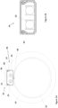
Figure 2A is an example of twosupply conduits 24 and an auxiliary conduit illustrated in cross-section which conduit in the embodiments described in the following is in the form of anair duct 32. Theair duct 32 may comprise a flow of air therein and may be in accordance with the standard ATA21 climate ducts. The air flow therein may be of a temperature above freezing, and which may be of a comfortable ambient temperature for an aircraft cabin. The air in theair duct 32 may be between 10 and 30°C, for example between 20 and 25°C, for example 20°C. Thesupply conduits 24 are located in anenclosure 34, which may be in the form of a raceway. Theenclosure 34 also provides a spray shield, spay protection cover or even a shrouding, so that additional safety measures can be avoided with. Illustrated in further detail inFigures 5 and 6 , the supply conduit(s) 24 (and in this example also the enclosure) extends along the length of theair duct 32 and may be physically connected to theair duct 32 by any appropriate means, for example by a bolt, tie, glue, or the like. In this example, thesupply conduits 24 are connected to theair duct 32 via theenclosure 34 in which they are located. Theenclosure 34 is therefore directly connected to theair duct 32, and may be connected to theair duct 32 in any appropriate way, such as by a bolt, tie, glue or the like. In this example, theenclosure 34 may be bolted or screwed in place. Thermal transfer may take place between the air duct 32 (e.g. an outer surface thereof, the flow of air therein, or the like) by conduction through the wall of theair duct 32 and through theenclosure 34. - The enclosure comprises a receiving
portion 40 in which acavity 36 is defined, and in which thesupply conduits 24 are located. The receivingportion 40 may be made from any suitable thermally conducting material such as aluminium, steel, or the like, to facilitate thermal conduction from theair duct 32 and into thecavity 36. Locating thesupply conduits 24 in thecavity 36 may physically protect thesupply conduits 24 e.g. from external forces such that they do not become dislodged, and/or may provide thermal protection to thesupply conduits 24 such that they are insulated against low temperatures external to theenclosure 34, and external to theair duct 32. In some examples, thecavity 36 may comprise an insulator therein. In addition, theenclosure 34 comprises acover 38. Thecover 38 is located radially outwardly of the receivingportion 40 in this example, although in other examples may be located in a different position on theenclosure 34. Thecover 34 may provide physical protection to the contents of the cavity 36 (e.g. the supply conduits 24) and may additionally provide thermal insulation thereto. In this example, thecover 38 comprises acover insulator 42 which may be located thereon or integrated into, or may define, thecover 38. - The
cover 38 may attach to the receivingportion 40 in any appropriate way, for example by a latch, screw, snapfit, magnet or the like. In this example, thecover 38 attaches to the receivingportion 40 via a snapfit connection. - Located radially outwardly of the
air duct 32 is aduct insulator 44. In this example the insulator extends circumferentially discontinuously around theair duct 32. Theinsulator 44 comprises a circumferential interruption 46 (e.g. a discontinuity) therein in which theenclosure 34 is located. In doing so, theduct insulator 44 may assist to insulate theenclosure 34, and may also permit theenclosure 34 to be located closer to theair duct 32, thus improving the thermal connection therebetween and increasing the rate at which thermal energy may be transferred between theair duct 32 and thesupply conduits 24 located in theenclosure 34. - Although not illustrated, the
enclosure 34 may comprise perforations therein to assist with heat conduction thereto, for example by permitting a direct connection between thecavity 36 and the outer surface of theair duct 32, and optionally by permitting convection heat transfer into thecavity 36, for example from the outer surface of theair duct 32. Acoupling 48, or a plurality thereof, may extend from theair duct 32 to theenclosure 34, for example may extend from a location internal to theair duct 32 to a location internal to theenclosure 34, for example for the purpose of increasing thermal conductivity therebetween. Thecoupling 48 may therefore assist to thermally couple thesupply conduit 24 to theair duct 32. Thecoupling 48 may be made from a material having high thermal conductivity such as aluminium, steel, or the like, and may permit thermal conductivity without interference from any insulators which may be surrounding theair duct 32. -
Figure 2B illustrates anenclosure 34 in further detail. In this example, thesupply conduits 24 are held in place by supports 50. The supports 50 may assist to hold thesupply conduits 24 in place relative to the receivingportion 40 and may be in any appropriate form such as a clip, jaw, tie or the like. - In
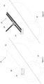
Figure 3 an alternative configuration of anair duct 32 andsupply conduit 24 are illustrated. In this example, only onesupply conduit 24 is illustrated alongside theair duct 32. Here, aninsulator 44 extends circumferentially continuously around theair duct 32. Thesupply conduit 24 is positioned radially outwardly of theinsulator 44 extends along an outer surface thereof. Thesupply conduit 24 may be held in place by any appropriate means, and in this example is held in place by fixingtape 52, although may also be held in place, for example, by a tie, chemical bond (e.g. glue) or the like. Asecondary insulator 54 is then laid over thesupply conduit 24, so as to thermally protect thesupply conduit 24 from the external environment, which may be in the fuselage of anaircraft 10 that may be prone to temperatures of less than the freezing temperature of the water in thesupply conduit 24. Thesecondary insulator 54 may equally be held in place by fixing tape, a tie, chemical bond or the like. Such a configuration may permit thesupply conduit 24 to be retrofitted onto existingair ducts 32. Although insulated, theair ducts 32 may provide sufficient heat that the temperature inside thesupply conduit 24 is able to be maintained above freezing. Although not illustrated, a thermal conductor (e.g. metal wire, such as copper wire, steel wire, aluminium wire) may extend through theinsulator 44 of theair duct 32 to improve the thermal conductivity to thesupply conduit 24. -
Figure 4 illustrates yet another configuration of anair duct 32 and asupply conduit 24. In this example, aninsulator 44 extends continuously circumferentially around theair duct 32, while asupply conduit 24 is contained in aninterstice 54 between theinsulator 44 and theair duct 32. However, it is also conceivable that the supply conduit 24' is positioned on the inner surface of theair duct 32 or integrated in the wall as indicated by the conduits 24' shown in dashed lines. Thesupply conduit 24 may be held in place by theinsulator 44, for example may be held to an outer surface of theair duct 32 by theinsulator 44. Alternatively or additionally, thesupply conduit 24 may be held in place by tape, a tie, chemical bonding (e.g. glue) or the like. In the configuration ofFigure 4 , no enclosure (e.g. as inFigure 2A and 2B ) may be required to hold thesupply conduit 24 and the lack of insulation between thesupply conduit 24 and the outer surface of theair duct 32 may permit a large degree of thermal energy transfer (e.g. by conduction) to occur between theair duct 32 and thesupply conduit 24. -
Figures 5 and 6 illustrate examples (similar to that ofFigure 2A and 2B ) in a perspective view. Here, it can be seen that thesupply conduit 24 and theenclosure 34 extend along the length of theair duct 32, and extend along thelongitudinal axis 56 of theair duct 32, e.g. parallel to thelongitudinal axis 56 or extending along thelongitudinal axis 56 in a helical shape around thelongitudinal axis 56. In the example ofFigure 5 , theenclosure 34 comprises acover 38, while in the example ofFigure 6 , no cover is present and theenclosure 34 is open. In this example, thesupply conduits 24 comprise abranch 58 which is able to extend from theenclosure 34. In some examples theenclosure 34 may comprise sections which are covered, and sections which are not covered, for example because they contain abranch 58. - A further example of an
air duct 32 andsupply conduits 24 is illustrated inFigure 7 . Here, theair duct 32 has a T-shape, as does one of the associatedsupply conduits 24. In this example, thesupply conduits 24 are connected (e.g. physically connected) to theair ducts 32, as well as also being thermally coupled thereto. Here, thesupply conduits 24 are contained in asleeve 60. Thesleeve 60 may be connected to the air duct 32 (e.g. directly to theair duct 32 or to theinsulator 44 of the air duct 32) by any appropriate means such as by a tie, cable, bolt, glue or the like. Thesleeve 60 may assist to connect (e.g. couple) thesupply conduit 24 to theair duct 32. As such, thesleeve 60 may be used to easily retrofit asupply conduit 24 to anair duct 32. - The
sleeve 60 may additionally be or comprise a thermal insulator. For example, a portion of thesleeve 60 that is located radially outwardly of thesupply conduit 34 may comprise a thermal insulator. In some examples theentire sleeve 60 may be or comprise a thermal insulator. Thus, thesleeve 60 may additionally protect thesupply conduit 24 from the conditions external thereto, thus assisting to maintain the temperature internal to thesupply conduit 24 above the freezing temperature of the water therein. - The
sleeve 60 may be in the form of a wrap, which may be able to be wrapped around thesupply conduit 24 or conduits, and may comprise a fastener (e.g. Velcro, a loop and hook or similar, etc.) to hold thesleeve 60 in place. Thesleeve 60 may be in the form of a spiral of material which may be positioned around thesupply conduit 24. - In such examples, the
sleeve 60 may be provided in place of an enclosure (as illustrated in the previous Figures) or may be provided in addition to an enclosure, such that the sleeve is located in the enclosure. -
Figure 8 illustrates anaircraft 10 in which a water supply system could be located. The aircraft comprisesfuselage 59 which may become very cold (e.g. may reach a temperature significantly below freezing temperature) during flight. The fuselage may additionally be made from metal and thus may be a poor insulator against the external cold temperatures during flight. Themain air duct 32 and thesupply conduit 24 can be installed in the triangle area of the aircraft, i.e. laterally below the cabin floor, e.g. in the form of a triangle module. However,air ducts 32 can also be designed as riser ducts following the circumference of the aircraft fuselage or they can be located in the crown area of an aircraft fuselage. -
- 10
- Aircraft
- 12
- Water supply system
- 14
- Central water tank
- 16
- Inlet (of central water tank)
- 18
- Water supply
- 20
- Outlet (of central water tank)
- 22
- Fluid pump
- 24
- Supply conduit
- 26
- User Equipment
- 28
- Aircraft installation
- 30
- Connection means
- 32
- Air duct
- 34
- Enclosure
- 36
- Cavity
- 38
- Cover
- 40
- Receiving portion
- 42
- Cover insulator
- 44
- Duct insulator
- 46
- Insulator interruption
- 48
- Coupling
- 50
- Support
- 52
- Fixing tape
- 54
- Secondary insulator
- 56
- Air duct longitudinal axis
- 58
- Branch
- 59
- Fuselage
- 60
- Sleeve
Claims (15)
- A water supply system (12) for use in an aircraft (10), the system (12) comprising:a central water tank (14) comprising a fluid inlet (16) and a fluid outlet (20);a supply conduit (24) for permitting fluid flow from the outlet (16) of the central water tank (14) to a user equipment (26);wherein at least a section of the supply conduit (24) is connected and thermally coupled to an aircraft auxiliary conduit (32) so as to enable a transfer of thermal energy to the supply conduit (24) therefrom to maintain the temperature of the water in the supply conduit (24) above the freezing temperature thereof.
- The water supply system (12) of claim 1, wherein the auxiliary conduit is an air duct (32).
- The water supply system (12) of claim 1 or 2, wherein the supply conduit (24) extends along the axial direction of the auxiliary conduit (32).
- The water supply system (12) of any preceding claim, wherein the supply conduit (24) is located within an enclosure (34), the enclosure (34) being coupled to the auxiliary conduit (32).
- The water supply system (12) of claim 4, wherein the enclosure (34) is an elongate enclosure (34) configured to extend along the axial direction of the auxiliary conduit (32).
- The water supply system (12) of claim 4 or 5, wherein the enclosure (34) is directly coupled to an external surface of an auxiliary conduit (32).
- The water supply system (12) of any of claims 4 to 6, wherein the enclosure (34) comprises a cover (38) located radially outwardly of the supply conduit (24), the cover (38) comprising a thermal insulator (42).
- The water supply system (12) of any preceding claim, wherein the supply conduit (24) is located between the auxiliary conduit (32) and a thermal insulator (44) extending circumferentially around the auxiliary conduit (32).
- The water supply system (12) of any of claims 1 to 7, wherein the supply conduit (24) is located in a discontinuity of a thermal insulator (44) extending circumferentially discontinuously around the auxiliary conduit (32).
- The water supply system (12) of any of claims 1 to 7, wherein the supply conduit (24) is located externally of a thermal insulator (44) extending circumferentially around an auxiliary conduit (32).
- The water supply system (12) of any preceding claim, wherein the diameter of the supply conduit (24) is smaller than the diameter of the auxiliary conduit (32).
- The water supply system (12) of any preceding claim, wherein the supply conduit (24) is thermally coupled to an auxiliary conduit (32) having an internal temperature of above 10 degrees Celsius, preferably between 10 and 30 degrees Celsius.
- The water supply system (12) of any preceding claim, comprising a plurality of supply conduits (24) coupled to the auxiliary conduit (32).
- A method for preventing freezing or icing in a water supply system (12) in an aircraft (10), comprising:providing a supply conduit (24) for permitting fluid flow from an outlet (20) of a central water tank (14) to a user equipment (26);thermally coupling the supply conduit (24) to an auxiliary conduit, preferably an aircraft air duct (32), so as to enable a transfer of thermal energy to the supply conduit (24) therefrom;providing thermal energy to the supply conduit (24) from the aircraft auxiliary conduit (32) so as to maintain the temperature of the water in the supply conduit (24) above the freezing temperature thereof.
- An aircraft (10) comprising the water supply system (12) of any of claims 1 to 13.
Priority Applications (3)
| Application Number | Priority Date | Filing Date | Title |
|---|---|---|---|
| EP23171369.4A EP4458673A1 (en) | 2023-05-03 | 2023-05-03 | Water supply system for use in an aircraft and a method for preventing freezing of water lines |
| CN202410529104.5A CN118895804A (en) | 2023-05-03 | 2024-04-29 | Water supply system, method for preventing freezing or icing, and aircraft |
| US18/653,376 US20240368860A1 (en) | 2023-05-03 | 2024-05-02 | Water supply system for use in an aircraft and a method for preventing freezing of water lines |
Applications Claiming Priority (1)
| Application Number | Priority Date | Filing Date | Title |
|---|---|---|---|
| EP23171369.4A EP4458673A1 (en) | 2023-05-03 | 2023-05-03 | Water supply system for use in an aircraft and a method for preventing freezing of water lines |
Publications (1)
| Publication Number | Publication Date |
|---|---|
| EP4458673A1 true EP4458673A1 (en) | 2024-11-06 |
Family
ID=86328755
Family Applications (1)
| Application Number | Title | Priority Date | Filing Date |
|---|---|---|---|
| EP23171369.4A Pending EP4458673A1 (en) | 2023-05-03 | 2023-05-03 | Water supply system for use in an aircraft and a method for preventing freezing of water lines |
Country Status (3)
| Country | Link |
|---|---|
| US (1) | US20240368860A1 (en) |
| EP (1) | EP4458673A1 (en) |
| CN (1) | CN118895804A (en) |
Citations (6)
| Publication number | Priority date | Publication date | Assignee | Title |
|---|---|---|---|---|
| US3378673A (en) * | 1965-10-18 | 1968-04-16 | Thomas O. Hopper | Electrically heated hose assembly |
| DE4227518A1 (en) * | 1991-09-30 | 1993-04-08 | Airbus Gmbh | DEVICE FOR WATER DISTRIBUTION |
| US7203419B2 (en) * | 2002-08-20 | 2007-04-10 | Heatsafe Cable Systems, Ltd | Heated conduit |
| US20130048128A1 (en) * | 2010-03-10 | 2013-02-28 | Airbus Operations Gmbh | Protection of water conduits against frost |
| US10822774B2 (en) * | 2017-04-07 | 2020-11-03 | Airbus Operations Gmbh | Aircraft comprising a high-pressure water supply and distribution system |
| US20220342431A1 (en) * | 2021-04-23 | 2022-10-27 | Airbus Operations Gmbh | Water supply system for an aircraft |
Family Cites Families (1)
| Publication number | Priority date | Publication date | Assignee | Title |
|---|---|---|---|---|
| US10488075B2 (en) * | 2013-06-18 | 2019-11-26 | B/E Aerospace, Inc. | Apparatus for pre-heating potable water in aircraft with waste heat |
-
2023
- 2023-05-03 EP EP23171369.4A patent/EP4458673A1/en active Pending
-
2024
- 2024-04-29 CN CN202410529104.5A patent/CN118895804A/en active Pending
- 2024-05-02 US US18/653,376 patent/US20240368860A1/en active Pending
Patent Citations (6)
| Publication number | Priority date | Publication date | Assignee | Title |
|---|---|---|---|---|
| US3378673A (en) * | 1965-10-18 | 1968-04-16 | Thomas O. Hopper | Electrically heated hose assembly |
| DE4227518A1 (en) * | 1991-09-30 | 1993-04-08 | Airbus Gmbh | DEVICE FOR WATER DISTRIBUTION |
| US7203419B2 (en) * | 2002-08-20 | 2007-04-10 | Heatsafe Cable Systems, Ltd | Heated conduit |
| US20130048128A1 (en) * | 2010-03-10 | 2013-02-28 | Airbus Operations Gmbh | Protection of water conduits against frost |
| US10822774B2 (en) * | 2017-04-07 | 2020-11-03 | Airbus Operations Gmbh | Aircraft comprising a high-pressure water supply and distribution system |
| US20220342431A1 (en) * | 2021-04-23 | 2022-10-27 | Airbus Operations Gmbh | Water supply system for an aircraft |
Also Published As
| Publication number | Publication date |
|---|---|
| CN118895804A (en) | 2024-11-05 |
| US20240368860A1 (en) | 2024-11-07 |
Similar Documents
| Publication | Publication Date | Title |
|---|---|---|
| US8015788B2 (en) | Heat transfer system for turbine engine using heat pipes | |
| CA2375565C (en) | Wellhead heating apparatus and method | |
| EP4365081B1 (en) | An aircraft comprising a high-pressure water supply and distribution system | |
| US8820362B2 (en) | Protection of water conduits against frost | |
| EP2817807B2 (en) | Arrangement for cooling power cables, power umbilicals and cables | |
| CN101479455B (en) | Turboreactor for aircraft | |
| CN109573054A (en) | Combined fluid is anti-icing and Electronic Cooling System | |
| US7694717B2 (en) | Profile traced insulated cover assembly | |
| EP2870610B1 (en) | Heat dissipation in a power cable or a power umbilical | |
| AU2020243441B2 (en) | Subsea pipelines equipped with direct electrical heating systems | |
| US20240368860A1 (en) | Water supply system for use in an aircraft and a method for preventing freezing of water lines | |
| US10906418B2 (en) | Apparatus for charging a plurality of electric vehicles | |
| USH2139H1 (en) | Active heating system for oil pipeline | |
| CN105026852B (en) | Solar energy field | |
| SE457006B (en) | PIPE STORAGE, WHICH ROERBROTT IS PREVENTED BY FREEZING, WITH ISOLATED CONNECTION WITH PRESSURE-RECORDING BODIES | |
| RU2411161C2 (en) | Aircraft engine nacelle anti-icing system with resistive layer | |
| CN117948539A (en) | Heating mechanism and temperature control method of hydrogenation gun for low temperature environment | |
| KR101174752B1 (en) | System for supressing of damage by cold wether for hot water boiler | |
| SE521197C2 (en) | Method and plant for effecting water circulation in a pipe system | |
| CN121947766A (en) | aircraft sections and aircraft | |
| CN221255626U (en) | Antifreezing device for water supply pipeline | |
| JP2004250861A (en) | Eco-airsystem | |
| US12228062B1 (en) | Diesel emissions control system | |
| KR20190067064A (en) | System for supressing of damage by cold wether for hot water boiler | |
| EP4280815A1 (en) | High-efficient silicone heater |
Legal Events
| Date | Code | Title | Description |
|---|---|---|---|
| PUAI | Public reference made under article 153(3) epc to a published international application that has entered the european phase |
Free format text: ORIGINAL CODE: 0009012 |
|
| STAA | Information on the status of an ep patent application or granted ep patent |
Free format text: STATUS: THE APPLICATION HAS BEEN PUBLISHED |
|
| AK | Designated contracting states |
Kind code of ref document: A1 Designated state(s): AL AT BE BG CH CY CZ DE DK EE ES FI FR GB GR HR HU IE IS IT LI LT LU LV MC ME MK MT NL NO PL PT RO RS SE SI SK SM TR |
|
| STAA | Information on the status of an ep patent application or granted ep patent |
Free format text: STATUS: REQUEST FOR EXAMINATION WAS MADE |
|
| 17P | Request for examination filed |
Effective date: 20250506 |
|
| RIC1 | Information provided on ipc code assigned before grant |
Ipc: B64D 11/02 20060101AFI20250829BHEP Ipc: B64D 11/04 20060101ALI20250829BHEP Ipc: B64D 15/02 20060101ALI20250829BHEP Ipc: F16L 53/32 20180101ALI20250829BHEP |
|
| STAA | Information on the status of an ep patent application or granted ep patent |
Free format text: STATUS: EXAMINATION IS IN PROGRESS |
|
| 17Q | First examination report despatched |
Effective date: 20251030 |