EP4458642A1 - Bogie, vehicle body, and rack vehicle - Google Patents
Bogie, vehicle body, and rack vehicle Download PDFInfo
- Publication number
- EP4458642A1 EP4458642A1 EP22939809.4A EP22939809A EP4458642A1 EP 4458642 A1 EP4458642 A1 EP 4458642A1 EP 22939809 A EP22939809 A EP 22939809A EP 4458642 A1 EP4458642 A1 EP 4458642A1
- Authority
- EP
- European Patent Office
- Prior art keywords
- transmission
- mounting
- mounting bases
- bogie
- traveling
- Prior art date
- Legal status (The legal status is an assumption and is not a legal conclusion. Google has not performed a legal analysis and makes no representation as to the accuracy of the status listed.)
- Pending
Links
Images










Classifications
-
- B—PERFORMING OPERATIONS; TRANSPORTING
- B61—RAILWAYS
- B61C—LOCOMOTIVES; MOTOR RAILCARS
- B61C9/00—Locomotives or motor railcars characterised by the type of transmission system used; Transmission systems specially adapted for locomotives or motor railcars
- B61C9/38—Transmission systems in or for locomotives or motor railcars with electric motor propulsion
- B61C9/48—Transmission systems in or for locomotives or motor railcars with electric motor propulsion with motors supported on vehicle frames and driving axles, e.g. axle or nose suspension
- B61C9/50—Transmission systems in or for locomotives or motor railcars with electric motor propulsion with motors supported on vehicle frames and driving axles, e.g. axle or nose suspension in bogies
-
- B—PERFORMING OPERATIONS; TRANSPORTING
- B61—RAILWAYS
- B61C—LOCOMOTIVES; MOTOR RAILCARS
- B61C11/00—Locomotives or motor railcars characterised by the type of means applying the tractive effort; Arrangement or disposition of running gear other than normal driving wheel
- B61C11/04—Locomotives or motor railcars characterised by the type of means applying the tractive effort; Arrangement or disposition of running gear other than normal driving wheel tractive effort applied to racks
-
- B—PERFORMING OPERATIONS; TRANSPORTING
- B61—RAILWAYS
- B61F—RAIL VEHICLE SUSPENSIONS, e.g. UNDERFRAMES, BOGIES OR ARRANGEMENTS OF WHEEL AXLES; RAIL VEHICLES FOR USE ON TRACKS OF DIFFERENT WIDTH; PREVENTING DERAILING OF RAIL VEHICLES; WHEEL GUARDS, OBSTRUCTION REMOVERS OR THE LIKE FOR RAIL VEHICLES
- B61F5/00—Constructional details of bogies; Connections between bogies and vehicle underframes; Arrangements or devices for adjusting or allowing self-adjustment of wheel axles or bogies when rounding curves
- B61F5/26—Mounting or securing axle-boxes in vehicle or bogie underframes
- B61F5/30—Axle-boxes mounted for movement under spring control in vehicle or bogie underframes
- B61F5/301—Axle-boxes mounted for movement under spring control in vehicle or bogie underframes incorporating metal springs
-
- B—PERFORMING OPERATIONS; TRANSPORTING
- B61—RAILWAYS
- B61F—RAIL VEHICLE SUSPENSIONS, e.g. UNDERFRAMES, BOGIES OR ARRANGEMENTS OF WHEEL AXLES; RAIL VEHICLES FOR USE ON TRACKS OF DIFFERENT WIDTH; PREVENTING DERAILING OF RAIL VEHICLES; WHEEL GUARDS, OBSTRUCTION REMOVERS OR THE LIKE FOR RAIL VEHICLES
- B61F5/00—Constructional details of bogies; Connections between bogies and vehicle underframes; Arrangements or devices for adjusting or allowing self-adjustment of wheel axles or bogies when rounding curves
- B61F5/50—Other details
- B61F5/52—Bogie frames
-
- F—MECHANICAL ENGINEERING; LIGHTING; HEATING; WEAPONS; BLASTING
- F16—ENGINEERING ELEMENTS AND UNITS; GENERAL MEASURES FOR PRODUCING AND MAINTAINING EFFECTIVE FUNCTIONING OF MACHINES OR INSTALLATIONS; THERMAL INSULATION IN GENERAL
- F16H—GEARING
- F16H55/00—Elements with teeth or friction surfaces for conveying motion; Worms, pulleys or sheaves for gearing mechanisms
- F16H55/02—Toothed members; Worms
- F16H55/17—Toothed wheels
Definitions
- the present application relates to the field of rack vehicles, and provides a bogie, a vehicle body and a rack vehicle.
- a rack railway is very suitable as a sightseeing route in mountainous areas or tourist attractions due to strong climbing capability, good safety and low construction costs. Especially when environmental protection restrictions have become more stringent recent years in China, the length of rack railway decreases greatly under the same climbing conditions compared with ordinary railway lines, thus, the environment of tourist attractions and areas with high environmental protection requirements is less impacted and the vegetation and geological environment along the route are effectively protected.
- the rack railway vehicles are less stable and comfortable since the rack rail adopted by the rack railway. After traveling gears of the rack vehicle wear, a center distance between the traveling gears and a rack will gradually decrease. However, due to the characteristics of the gear-rack transmission, it cannot adapt to the large amount of wheel wear. After wheels wear, the traveling gears or wheels need to be replaced, which results in higher maintenance costs.
- An embodiment of the present application provides a bogie, which solves the defects of poor stability and comfort of a rack railway vehicle in related art and improves the stability and comfort of the rack railway vehicle.
- An embodiment of the present application provides a bogie, including:
- the pair of traveling gears and the pair of drive members are provided, and the pair of drive members are connected to the pair of traveling gears through the transmission devices, and the transmission devices are respectively provided on sides away from the pair of traveling gears along the transverse direction of the frame, the drive members, the transmission devices, and the traveling gears form a Z-shaped structure in sequence, which makes the traveling structure of the bogie more stable and improves the operating stability of the vehicle.
- the pair of traveling gears By mounting the pair of traveling gears on the axle through the eccentric device, it is only necessary to adjust the position of the traveling gears relative to a meter-gauge track without changing the position structure of a drive device during the process of adjusting the height of the traveling gears.
- the height of the traveling gears can be precisely adjusted, ensuring accurate meshing of the traveling gears with the meter-gauge track. Therefore, the bogie also has the advantages of simple structure, convenient maintenance and low maintenance costs.
- the eccentric device includes:
- the bogie further includes a first support bracket mounted on the frame, a plurality of mounting holes for mounting the first support bearing are provided on the first support bracket, and a plurality of first positioning holes are provided on an end surface of the mounting holes along a circumferential direction of the mounting holes;
- the locking mechanism includes:
- a first bushing is further sleeved on the outer circumference of the first eccentric wheel, and the first bushing is configured to reduce a friction between an outer circumference of the first eccentric wheel and an inner wall of the mounting holes.
- the number of the first eccentric wheel is two, and a synchronization block is provided between the two first eccentric wheels.
- a projection of the wheelsets is located within a projection of the frame in a plane parallel to a meter-gauge track.
- the bogie further includes a secondary damping device, where the secondary damping device includes a bottom plate connected to a top of the side beams and an air spring mounted on the bottom plate, and the air spring is conical in a direction from the bottom plate away from the side beams.
- the bogie further includes an anti-roll device mounted on each of the side beams, and the anti-roll device includes:
- the bogie further includes a first braking device and a second braking device
- the bogie further includes a rim lubricating device, mounted on each of the side beams and facing the two traveling gears respectively.
- An embodiment of the present application provides a vehicle body, including the above-mentioned bogie, which is mounted below the vehicle body.
- the stability of the vehicle body can be improved and the shaking and vibration amplitude of the vehicle body can be reduced.
- An embodiment of the present application provides a rack vehicle, including the above-mentioned bogie or the above-mentioned vehicle body.
- the rack vehicle provided by the third embodiment of the present application, by providing the above-mentioned bogie or vehicle body, it can not only improve the riding experience of passengers, but also adapt to rack railways of different specifications.
- the rack vehicle further includes a traveling gear structure for the rack vehicle
- the plurality of first elastic portions form an elastic assembly along the circumferential direction of the first toothed ring portion; and two elastic assemblies are symmetrically disposed on both sides of the first toothed ring portion along an axial direction.
- the present embodiment provides an implementation of the first elastic portion, by symmetrically disposing the first elastic portions on both sides of the first toothed ring portion along the axial direction of a first axle sleeve, and disposing the plurality of first elastic portions annularly, the capability of the traveling gear to transmit torque is improved while an eccentric load of the traveling gear is decreased, and the impact of the gear meshing process is reduced, a large torque of the traveling gear is transmitted and needs of the rack vehicle are satisfied.
- the traveling gear structure further includes: a second bushing, the second bushing is disposed between the inner ring of the first toothed ring portion and the outer ring of the first transmission portion to decrease a friction coefficient between the first toothed ring portion and the first transmission portion.
- the present embodiment provides an implementation of the second bushing. By disposing the second bushing, the friction coefficient is decreased, and a friction problem caused by relative displacement between the first toothed ring portion and the first transmission portion is solved.
- the traveling gear structure further includes: a plurality of first mounting bases A and a plurality of second mounting bases A;
- the present embodiment provides an implementation of the first mounting bases A and the second mounting bases A.
- the first elastic portions are mounted and positioned at the side of the first toothed ring portion.
- the first transmission portion includes: a first transmission connecting base, a first transmission supporting base and a plurality of first connecting units;
- the present embodiment provides an implementation of the first transmission connecting base, the first transmission supporting base and the first connecting units. By disposing the first transmission connecting base, the first transmission supporting base and the first connecting units, the connection between the first transmission portion and the first toothed ring portion is more convenient.
- first toothed ring portion and the first transmission portion are connected through the first elastic portions.
- the inner ring gears provided on the inner ring of the first boss provides the transmission connection between the traveling gear and an external gear corresponding thereto, which facilitates the installation and disassembly of the traveling gear.
- each of the second mounting bases A includes: a plurality of first sub-mounting bases A and a plurality of second sub-mounting bases A;
- the present embodiment provides an implementation of the first sub-mounting bases A and the second sub-mounting bases A.
- the first elastic portions are disposed on both sides of the first toothed ring portion.
- first mounting bases A and the first sub-mounting bases A are disposed staggeredly on the first side of the first toothed ring portion, and the first mounting bases A and the second sub-mounting bases A are disposed staggeredly on the second side of the first toothed ring portion, the connection and installation positions of the first elastic portion on both sides of the first toothed ring portion are formed.
- At least part of the first connecting units are shear-resistant pins.
- the present embodiment provides an implementation of the first connecting units. By configuring part of the first connecting unit as shear-resistant pins, the stability of the connection between the first transmission connecting base and the first transmission supporting base is improved.
- each of the first elastic portions includes: a first mounting plate A, a second mounting plate A and a first elastomer;
- the present embodiment provides an implementation of the first mounting plate A, the second mounting plate A, and the first elastomer.
- an annular elastic buffer structure composed of a plurality of first elastomers is formed on a side of the first toothed ring portion.
- first mounting plates A and the second mounting plates A also enables the first elastomers to be disassembled and maintained more conveniently.
- first elastomer loses elasticity or is damaged, only the independent first elastomer needs to be disassembled for maintenance and replacement, which improves work efficiency.
- the first elastomer is an elastic block made of a rubber material.
- the present embodiment provides an implementation of the first elastomer.
- the first elastomer By configuring the first elastomer as an elastic block made of the rubber material, the capability of the traveling gear to transmit torque is improved, and at the same time, when the traveling gear is subjected to a certain eccentric load or impact, the eccentric load or impact can be effectively absorbed by the first elastomer.
- the rack vehicle further includes a drive device for the rack vehicle
- the second adjusting assembly includes: a first bearing B, a second bearing B and a third eccentric wheel;
- the second adjusting assembly further includes: a second adjusting disc, the second adjusting disc is connected to the third eccentric wheel to adjust a steering of the third eccentric wheel through the second adjusting disc.
- the two second adjusting assemblies are symmetrically disposed on both sides of the traveling gear along the axial direction of the second axle sleeve.
- the drive device further includes: a second brake disc, a second brake cylinder and a second brake caliper;
- the traveling gear includes: a second toothed ring portion, a second transmission portion and a plurality of second elastic portions;
- the traveling gear further includes: a plurality of first mounting bases B and a plurality of second mounting bases B;
- the second transmission portion includes: a second transmission connecting base, a second transmission supporting base and a plurality of second connecting units;
- each of the second mounting bases B includes: a plurality of first sub-mounting bases B and a plurality of second sub-mounting bases B;
- each of the second elastic portions includes: a first mounting plate B, a second mounting plate B and a second elastomer;
- the pair of traveling gears and the pair of drive members are provided, and the pair of drive members are connected to the pair of traveling gears through the transmission devices, and the transmission devices are respectively provided on sides away from the pair of traveling gears along a transverse direction of the frame, thus, the drive members, the transmission devices, and the traveling gears form a Z-shaped structure in sequence, which makes the traveling structure of the bogie more stable and improves the operating stability of the vehicle.
- the pair of traveling gears By mounting the pair of traveling gears on the axle through the eccentric device, it is only necessary to adjust the position of the traveling gears relative to a meter-gauge track without changing the position structure of a drive device during the process of adjusting the height of the traveling gears. Through the above adjustments, the height of the traveling gears can be precisely adjusted, ensuring accurate meshing of the traveling gears with the meter-gauge track.
- the bogie also has the advantages of simple structure, convenient maintenance and low maintenance costs.
- the stability of the vehicle body can be improved and the shaking and vibration amplitude of the vehicle body can be reduced.
- the rack vehicle provided by the third embodiment of the present application, by providing the above-mentioned bogie or vehicle body, it can not only improve the riding experience of passengers, but also adapt to rack railways of different specifications.
- orientation or positional relations specified by terms such as “central”, “longitudinal”, “lateral”, “up”, “down”, “front”, “back”, “left”, “right”, “vertical”, “horizontal”, “top”, “bottom”, “inner”, “outer” and the like are based on the orientation or positional relations shown in the drawings, which is merely for convenience of description of the present application and to simplify description, but does not indicate or imply that the stated devices or components must have a particular orientation and be constructed and operated in a particular orientation, and thus it is not to be construed as limiting the present application.
- the terms “first”, “second”, “third” and the like are only used for descriptive purposes and should not be construed as indicating or implying a relative importance.
- connection to and “connected” shall be understood broadly, for example, it may be either fixedly connected or detachably connected, or can be integrated; it may be either mechanically connected, or electrically connected; it may be either directly connected, or indirectly connected through an intermediate medium.
- connection to and “connected” shall be understood broadly, for example, it may be either fixedly connected or detachably connected, or can be integrated; it may be either mechanically connected, or electrically connected; it may be either directly connected, or indirectly connected through an intermediate medium.
- a first feature is "on” or “under” a second feature can refer to that the first feature is directly contacted with the second feature, or the first feature is indirectly contacted with the second feature through an intermediate medium.
- the first feature is "on”, “above” and “over” the second feature can refer to that the first feature is directly above or obliquely above the second feature, or simply refer to that the level height of the first feature is higher than that of the second feature.
- a first feature is "under”, “below” and “beneath” a second feature can refer to that the first feature is directly below or obliquely below the second feature, or simply refer to that the level height of the first feature is lower than that of the second feature.
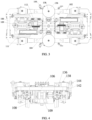
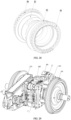
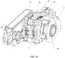
- the present application provides a bogie, including a frame 100, two wheelsets 108, a pair of traveling gears 109, and a pair of drive members 112.
- the frame 100 includes a pair of side beams 102, a pair of cross beams 104 and a pair of end beams 106 oppositely disposed, both ends of the pair of cross beams 104 are respectively connected between the pair of side beams 102 and the pair of end beams 106 are respectively connected to both ends of the pair of side beams 102.
- Two wheelsets 108 are rotatably mounted on the frame 100 through axles 110 and respectively located in an area surrounded by the end beams 106, cross beams adjacent to the end beams 104 and the pair of side beams 102.
- the pair of traveling gears 109 are respectively mounted on the axle 110 through an eccentric device and disposed along a longitudinal axis of the frame 100.
- the pair of drive members 112 are respectively mounted on the cross beams 104, and respectively in transmission connection with the pair of traveling gears 109 through transmission devices 111, and the transmission devices 111 are respectively provided on sides away from the pair of traveling gears 109 along a transverse direction of the frame 100.
- the pair of traveling gears 109 and the pair of drive members 112 are provided, and the pair of drive members 112 are connected to the pair of traveling gears 109 through the transmission devices 111, and the transmission devices 111 are respectively provided on sides away from the pair of traveling gears 109 along a width direction of the frame 100, the drive members 112, the transmission devices 111, and the traveling gears 109 form a Z-shaped structure in sequence, which makes the traveling structure of the bogie more stable and improves the operating stability of the vehicle.
- the bogie By mounting the pair of traveling gears 109 on the axle 110 through the eccentric device, it is only necessary to adjust the position of the traveling gears 109 relative to a meter-gauge track without changing the position structure of a drive device during the process of adjusting the height of the traveling gears 109. Through the above adjustments, the height of the traveling gears 109 can be precisely adjusted, ensuring accurate meshing of the traveling gears 109 with the meter-gauge track. Therefore, the bogie also has the advantages of simple structure, convenient maintenance and low maintenance costs.
- the frame 100 is configured to mount components such as the wheelset 108, the traveling gears 109, the drive members 112, etc.
- the frame 100 includes the pair of side beams 102, the pair of cross beams 104 and the pair of end beams 106 that are oppositely disposed.
- the pair of side beams 102 and the pair of end beams 106 are formed by welding steel plates, and the pair of cross beams 104 are made of seamless steel pipes.
- Both ends of the pair of cross beams 104 are respectively connected between the pair of side beams 102. It can be understood that in the embodiment of the present application, the pair of side beams 102, the pair of end beams 106 and the pair of cross beams 104 are spliced to form a structure with a shape of Unicode character U+76EE, which increases the structural strength of the frame 100, and solves the problem of insufficient installation space in the bogie of the rack vehicle.
- Two wheelsets 108 are mounted on the frame 100 through axles 110 and respectively located in a mounting space surrounded by the end beams 106, the cross beams 104 adjacent to the end beams 106 and the pair of side beams 102.
- the axle 110 mentioned here may be hollow shafts, which reduces the weight of the axle 110 and also facilitates maintenance personnel to detect flaws in the axle 110.
- the pair of traveling gears 109 are respectively mounted on the axle 110 through an eccentric device and disposed along a longitudinal axis of the frame 100.
- the longitudinal direction of the frame 100 mentioned here refers to the length direction of the frame 100, that is, left and right directions as shown in FIG. 3 .
- the transmission devices 111 in transmission connection between the pair of drive members 112 and the pair of traveling gears are respectively provided on sides away from the pair of traveling gears 109 along the transverse direction of the frame 100.
- the transmission device 111 on the left is located below the traveling gear 109 on the left, and the transmission device 111 on the right is located above the traveling gear 109 on the right, which ensures the balance performance of the bogie in the upward and downward directions as shown in FIG. 3 and avoids uneven weight distribution of the bogie in the upward and downward directions.
- the traveling gear 109 on the left, the transmission device 111 on the left, the drive member 112 on the left, the traveling gear 109 on the right, the transmission device 111 on the right, and the drive member 112 on the right are formed in sequence similar to a Z-shaped structure.
- the transmission device 111 and the drive member 112 at one side are connected to the side beams 102 using bolts, which avoids stress concentration at the connection part of the side beams 102.
- the traveling gears 109 are mounted on the axle 110 through an eccentric device.
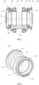
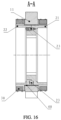
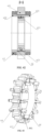
- the eccentric device includes a pair of first support bearings 114, a pair of second support bearings 118 and a pair of first eccentric wheels 116.
- Inner rings of the pair of first support bearings 114 are sleeved on the axle 110.
- the pair of first eccentric wheels 116 are sleeved on outer rings of the first support bearings 114 and eccentrically provided with respect to the axle 110, and a position of the first eccentric wheels 116 relative to the first support bearings 114 is locked through a locking mechanism.
- Inner rings of the pair of second support bearings 118 are sleeved outside the first eccentric wheels 116, and the traveling gears 109 are sleeved on outer rings of the second support bearings 118.
- the position of the traveling gears 109 relative to the axle 110 are adjustable, that is, a height h of the traveling gears 109 relative to the axle 110 is adjustable. In this way, in the process of adjusting the height of the traveling gears 109, it is only necessary to adjust the position of the first eccentric wheels 116 relative to the first support bearings 114, without changing the position and structure of the drive device.
- the bogie Through adjusting the first eccentric wheels 116, the height of the traveling gears 109 can be precisely adjusted, ensuring accurate meshing of the traveling gears 109 with the meter-gauge track. Therefore, the bogie also has the advantages of simple structure, convenient maintenance and low maintenance costs.
- the first support bearings 114 are sleeved on the axle 110. There are two first support bearings 114, and the two first support bearings 114 are spaced apart on the axle 110. The axes of the two first support bearings 114 are collinear with the axis of the axle 110.
- the first eccentric wheel 116 is sleeved on an outer circumferential surface of the first support bearings 114.
- the axis L1 of the first eccentric wheel 116 is eccentrically disposed with respect to the axis L2 of the axle 110. Since the number of the first support bearings 114 is two, the number of the first eccentric wheels 116 is two and the two first eccentric wheels 116 are respectively sleeved on the outer rings of the two first support bearings 114.
- the position of the first eccentric wheels 116 relative to the first support bearings 114 can be locked by a locking mechanism.
- first eccentric wheels 116 and the axle 110 are eccentrically disposed
- the first eccentric wheels 116 and the first support bearings 114 are also eccentrically disposed.
- the relative position of the axis of the first eccentric wheels 116 and the axis of the axle 110 can be adjusted.
- the relative position therebetween can be locked by a locking mechanism.
- the second support bearings 118 is sleeved outside the first eccentric wheels 116, and the traveling gears 109 is sleeved on the outer rings of the second support bearings 118.
- the relative position of the first eccentric wheels 116 and the axle 110 can be adjusted synchronously, and the position of the traveling gears 109 relative to the axle 110 can be adjusted, which ensures that the traveling gears 109 can always be meshed with the meter-gauge track, stably drives the rack vehicle and ensures that the traveling gears 109 can still be meshed with the meter-gauge track even if the traveling gears 109 wear.
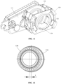
- the bogie further includes a first support bracket 120 mounted on the frame 100.
- the first support bracket 120 is provided with a plurality of mounting holes 122 for mounting the first support bearings 114.
- a plurality of first positioning holes 124 are provided on an end surface of the mounting holes 122 along the circumferential direction of the mounting holes 122.
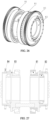
- the locking mechanism includes an adjusting ring 126 and a locking member 130; where the adjusting ring 126 is connected to an outer circumference of the first eccentric wheels 126, where a plurality of second positioning holes 128 are provided on an end surface of the adjusting ring 126 along a circumferential direction of the adjusting ring 126.
- the locking member 130 penetrates through the first positioning holes 124 and the second positioning holes 128 to lock a position of the first eccentric wheels 116 relative to the first support bracket 120.
- the bogie further includes a first support bracket 120, and the first support bracket 120 is mounted on the frame 100.
- the first support bracket 120 is used for mounting the transmission device 111, the first support bearings 114, the axle 110 and other parts.
- the first support bracket 120 is provided with a plurality of mounting holes 122 for mounting the first support bearings 114.
- a plurality of equally spaced first positioning holes 124 are provided on the end surface of the mounting holes 122 along the circumferential direction of the mounting holes 122.
- the locking mechanism can be connected with the first positioning holes 124 on the end surface of the mounting holes 122 of the first support bracket 120 to lock the first eccentric wheels 116 and the first support bracket 120.
- the locking mechanism includes the adjusting ring 126 for locking with the first support bracket 120 and the locking member 130 for locking the relative position of the adjusting ring 126 and the first support bracket 120.
- the adjusting ring 126 is connected to an outer circumferential surface of each of the first eccentric wheels 116.
- the adjusting ring 126 is provided with second positioning holes 128 in one-to-one correspondence with the first positioning holes 124 along the circumferential direction of the adjusting ring 126.
- the locking member 130 penetrates through the second positioning holes 128 on the adjusting ring 126 and the first positioning holes 124 on the first support bracket 120 to lock the adjusting ring 126 to the first support bracket 120.
- the position of the first support bracket 120 is fixed.
- the relative rotation angle between the adjusting ring 126 and the first support bracket 120 can be adjusted.
- the locking member 130 penetrates through the second positioning holes 128 and the first positioning holes 124 to lock the adjusting ring 126 and the first support bracket 120 with each other. That is, the relative position of the traveling gears 109 and the axel can be locked by locking the relative position of the first eccentric wheels 116 and the first support bracket 120, thereby adjusting the height of the traveling gears 109.
- a transmission device 111 is also integrated on the first support bracket 120, which makes the structure of the bogie more compact.
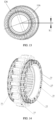
- an inner ring gear 154 is provided on the inner wall of the adjusting ring 126, and an outer ring gear 156 is provided on the outer circumference of the first eccentric wheels 116.
- the inner ring gear 154 is meshed with the outer ring gear 156 to connect the adjusting ring 126 with the first eccentric wheels 116.
- the adjustment accuracy of enabling the adjusting ring 126 to drive the first eccentric wheels 116 is higher. That is, when the adjusting ring 126 is rotated, the first eccentric wheels 116 can be precisely adjusted through the meshing transmission of the inner ring gear 154 and the outer ring gear 156.
- the mode of adjusting the adjusting ring 126 and the first eccentric wheels 116 can also be performed in other ways. For example, a positioning boss can be provided on the inner wall of the adjusting ring 126 and a positioning protrusion can be provided on the outer circumference of the first eccentric wheels 116.
- the outer ring of the adjusting ring 126 is provided with a snap-fit slot 158.
- a first bushing 132 is sleeved on the outer circumference of each of the first eccentric wheels 116, and the first bushing 132 is configured to reduce a friction between the outer circumference of the first eccentric wheels 116 and the inner wall of the mounting holes 122.
- a first bushing 132 is sleeved on the outer circumference of each of the first eccentric wheels 116.
- the outer circumferential surface of the first bushing 132 is attached to the inner wall of the mounting holes 122 on the first support bracket 120 to reduce the friction force between the outer circumferential surface of the eccentric wheel 116 and the inner wall of the mounting holes 122. It can be understood that when the first bushing 132 and the mounting holes 122 on the first support bracket 120 are nested with each other, each of the first eccentric wheels 116 can rotate around the axis of the first bushing 132.
- an annular positioning stage 160 is provided on the outer wall of the first eccentric wheels 116 along the circumferential direction of the first eccentric wheels 116.
- the first bushing 132 includes a collar 162 and a retaining ring 164; the collar 162 is sleeved on the outer circumference of each of the first eccentric wheels 116; the retaining ring 164 is sleeved on the outer circumference of the collar 162 and is configured to abut against and matched with the annular positioning stage 160.
- annular positioning stage 160 is provided on the circumferential surface of each of the first eccentric wheels 116.
- the annular positioning stage 160 can position the axial position of the first bushing 132 relative to the first eccentric wheels 116.
- the first bushing 132 includes a collar 162 and a retaining ring 164.
- the collar 162 is directly sleeved on the outer circumference of each of the first eccentric wheels 116.
- the retaining ring 164 is disposed on the circumferential surface of the collar 162 and abuts against an annular positioning stage 160 on the circumferential surface of each of the first eccentric wheels 116, thus, the axial position of the first bushing 132 relative to the first eccentric wheels 116 can be limited.
- mounting slots 166 are provided on opposite sides of the two first eccentric wheels 116, and synchronization blocks 134 are provided in the mounting slots 166.
- mounting slots 166 are provided on the opposite sides of the two first eccentric wheels 116. Synchronizing blocks 134 are inserted into the mounting slots 166 of the first eccentric wheels 116.
- the projection of the wheelset 108 is located within the projection of the frame 100.
- the frame 100 is externally placed, which facilitates maintenance and repair of the frame 100. It can also meet the track gauge requirements of the rack vehicle.
- the frame 100 is relatively stabler.
- a secondary damping device is also provided on the side beams 102 of the frame 100.
- the secondary damping device is mounted between the side beams 102 and the vehicle body.
- the secondary damping device includes an air spring 138.
- the air spring 138 can adopt a conical air spring 138 with large displacement capacity, small vertical and lateral stiffness, and large effective diameter. This can ensure the vibration damping performance of the vehicle body and improve the riding experience of the passenger.
- the secondary damping device further includes a bottom plate 136 disposed between the bottom of the air spring 138 and the side beams 102.
- the bottom plate 136 can adopt a circular structure, which can increase the contact area and avoid stress concentration on the bogie body.
- the secondary damping device can also be equipped with a lateral damper to reduce the vibration amplitude of the vehicle body in the lateral direction.
- the air spring 138 is a conical spring, and the air spring 138 is conical in a direction away from the side beam 102 from the bottom plate 136.
- the bogie further includes an anti-roll device.
- the anti-roll device is mounted on the side beams 102.
- the anti-roll device includes a bearing seat 140, a torsion bar shaft and an anti-roll torsion bar 142.
- the bearing seat 140 is mounted at the bottom of each of the side beams 102; the torsion bar shaft is mounted in the bearing seat 140; the anti-roll torsion bar 142 is connected between the torsion bar shaft and the vehicle body and a ball hinge structure 144 is provided at an end of the anti-roll torsion bar 142 connected to the vehicle body.
- the bearing seat 140 is mounted at the bottom of each of the side beams 102 and is configured to fix the torsion bar shaft.
- the bearing seat 140 can be mounted at the bottom of the side beam 102 through bolts.
- Both ends of the anti-roll torsion bar 142 are respectively connected between the ends of the torsion bar shaft and the vehicle body.
- a ball hinge structure 144 is provided at an end of the anti-roll torsion bar 142 connected to the vehicle body.
- the bogie further includes a first braking device, and the first braking device includes a mounting bracket 146 and brake shoes 148, where the mounting bracket 146 is mounted at the bottom of the side beam 102; the brake shoes 148 are provided on the mounting bracket 146 and opposite to a tread of the wheelsets 108.
- the first braking device is disposed in the form of the mounting bracket 146 and the brake shoes 148, which ensures that the first braking device has the advantages of simple structure and good economy.
- the mounting bracket 146 is mounted on the side beam 102, and the mounting bracket 146 is used for mounting the brake shoes 148.
- the shape of the brake shoes 148 is adapted to the shape of the tread of the wheelset 108. When the brake shoes 148 are attached to the tread of the wheelset 108, the friction force between the brake shoes 148 and the tread of the wheelset 108 can lock the wheelset 108, thereby providing the braking function.
- the bogie further includes a second braking device 150.
- the second braking device 150 includes a brake disc, two friction rings and a brake cylinder.
- the brake disc and the wheelset 108 are coaxially disposed, two friction rings are respectively provided on opposite sides of the wheelset 108, and a heat dissipation structure is disposed between the two friction rings.
- the brake cylinder is a provided on the side beam 102 and is used for driving the two friction rings to move relative to the wheelset 108.
- the second braking device 150 by disposing the second braking device 150 in the form of the friction rings and a brake cylinder, the overall structure of the second braking device 150 is compact and occupies a small space.
- the brake disc is coaxially disposed with the wheelset 108.
- the brake disc can be disposed on the axle 110 on which the wheelset 108 is mounted.
- a hollow shaft is disposed on the wheelset 108 and supported by bearings and relative rotation is generated between the hollow shaft and the axle 110 to enable the hollow shaft to transmit driving torque, which solves transmission problem and a problem of vehicle operation on large slopes.
- the brake cylinder is disposed on the bogie body, and the two friction rings are respectively disposed on both sides of the wheelset 108.
- the brake cylinder supplies oil to the two friction rings, the two friction rings are driven to act in the direction of clamping the brake disc.
- the bogie further includes a rim lubricating device 152, mounted on each of the side beams 102 and facing the two traveling gears 109 respectively.
- the rim lubricating device 152 is provided at the traveling gear 109. By disposing the rim lubricating device 152, the wheel-rail space can be lubricated regularly and the problem of abnormal wear between the wheel-rail space can be solved.
- An embodiment of the present application provides a vehicle body, including a vehicle main body and the above-mentioned bogie, and the bogie is mounted below the vehicle main body.
- the stability of the vehicle body can be improved and the shaking and a vibration amplitude of the vehicle body can be reduced.
- An embodiment of the present application provides a rack vehicle, including the above-mentioned bogie or the above-mentioned vehicle body.
- the rack vehicle provided by the third embodiment of the present application, by providing the above-mentioned bogie or vehicle body, it can not only improve the riding experience of passengers, but also adapt to rack railways of different specifications.
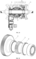
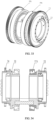
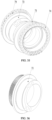
- the present application provides a traveling gear structure for a rack vehicle, including: a first toothed ring portion 10, a first transmission portion 20 and a plurality of first elastic portions 30.
- An outer ring of the first toothed ring portion 10 is provided with a first outer gear teeth 11, and the first outer gear teeth 11 are meshed with a rack provided on the ground.
- An outer ring of the first transmission portion 20 is matched with an inner ring of the first toothed ring portion 10.
- the plurality of first elastic portions 30 are evenly distributed on the side of the first toothed ring portion 10 along the circumferential direction, and are respectively connected to the first toothed ring portion 10 and the first transmission portion 20.
- the present application provides a traveling gear structure for a rack vehicle to solve the problem of large impact and vibration due to the characteristics of gear and rack transmission, which reduces the riding comfort and causes problems for the equipment on the vehicle.
- a traveling gear structure for a rack vehicle to solve the problem of large impact and vibration due to the characteristics of gear and rack transmission, which reduces the riding comfort and causes problems for the equipment on the vehicle.
- the plurality of first elastic portions 30 form an elastic assembly along the circumferential direction of the first toothed ring portion 10, and two elastic assemblies are symmetrically disposed on both sides of the first toothed ring portion 10 along an axial direction.
- the present embodiment provides an implementation of the first elastic portions 30, by symmetrically disposing the first elastic portions 30 on both sides of the first toothed ring portion 10 along the axial direction of a first axle sleeve 77, and disposing the plurality of first elastic portions 30 annularly, the capability of the traveling gear to transmit torque is improved while an eccentric load of the traveling gear is decreased and the impact of the gear meshing process is reduced, and a large torque of the traveling gear is transmitted and needs of the rack vehicle are satisfied.
- disposing the first elastic portions 30 increases the damping of the traveling gear, reduces noise caused by meshing between the gear and the rack, reduces the vibration experienced by the rack vehicle during driving, and improves the riding comfort.
- the two groups of elastic assemblies are symmetrically disposed, which solves the need for the traveling gear to transmit very high torque when the rack vehicle operates on a large slope.
- each elastic assembly includes a plurality of first elastic portions 30 disposed annularly. This arrangement improves the uniformity of the load and impacts and vibrations experienced by the traveling gears can be absorbed well.
- an elastic assembly composed of a plurality of first elastic portions 30 is disposed on the side of the first toothed ring portion 10, radial space is freed and a larger transmission structure is connected internally, which improves the performance of a transmission system.
- the traveling gear structure further includes a second bushing 40.
- the second bushing 40 is disposed between the inner ring of the first toothed ring portion 10 and the outer ring of the first transmission portion 20 to decrease a friction coefficient between the first toothed ring portion 10 and the first transmission portion 20.
- the present embodiment provides an implementation of the second bushing 40.
- the friction coefficient is decreased, and a friction problem caused by relative displacement between the first toothed ring portion 10 and the first transmission portion 20 is solved.
- the second bushing 40 is made of a self-lubricating material.
- the second bushing 40 is made of a carbon-based material.
- the second bushing 40 is a self-lubricating bushing.
- the traveling gear structure further includes a plurality of first mounting bases A 50 and a plurality of second mounting bases A 60.
- the first mounting bases A 50 are evenly distributed on a side of the first toothed ring portion 10 along the circumferential direction; the second mounting bases A 60 are evenly distributed on the outer ring of the first transmission portion 20 along the circumferential direction, and the first mounting bases A 50 and the second mounting bases A 60 are disposed staggeredly.
- the first elastic portions 30 are detachably connected to the adjacent first mounting bases A 50 and the second mounting bases A 60, respectively.
- the present embodiment provides an implementation of the first mounting bases A 50 and the second mounting bases A 60.
- the first elastic portions 30 are mounted and positioned at the side of the first toothed ring portion 10.
- first mounting bases A 50 and the second mounting bases A60 are disposed staggeredly on the side of the first toothed ring portion 10, and the first mounting bases A 50 and the second mounting bases A 60 are provided with connection structure such as mounting holes.
- the first elastic portions 30 are respectively connected to the first mounting bases A 50 and the second mounting bases A 60 through screws or other connecting components.
- the first elastic portions 30 provided in the first mounting bases A 50 and the second mounting bases A 60 are deformed to absorb impact and vibration.
- the first transmission portion 20 includes: a first transmission connecting base 21, a first transmission supporting base 22 and a plurality of first connecting units 23.
- a first boss 24 is provided on a first side of the first transmission connecting base 21, and an inner ring of the first boss 24 is provided with inner ring gears.
- the first transmission supporting base 22 is insertedly matched with the first transmission connecting base 21 through the first boss 24.
- the plurality of first connecting units 23 are provided on a matching surface of the first transmission connecting base 21 and the first transmission supporting base 22 to detachably connect the first transmission connecting base 21 and the first transmission supporting base 22.
- the plurality of second mounting bases A 60 are evenly distributed on the outer rings of the first transmission connecting base 21 and the first transmission supporting base 22 along the circumferential direction.
- the present embodiment provides an implementation of the first transmission connecting base 21, the first transmission supporting base 22 and the first connecting units 23.
- the first transmission portion 20 is more conveniently connected to the first toothed ring portion 10.
- first toothed ring portion 10 and the first transmission portion 20 are connected through the first elastic portions 30.
- the inner ring gears provided on the inner ring of the first boss 24 provide the transmission connection between the traveling gear and an external gear corresponding thereto, which facilitates the installation and disassembly of the traveling gears.
- the matching surface of the first transmission connecting base 21 and the first transmission supporting base 22 is provided with corresponding mounting holes or screw holes, and connectors are matched with the mounting holes or screw holes to connect the first transmission connecting base 21 to the first transmission supporting base 22.
- the present application does not describe the connection in too much detail. Please refer to the accompanying drawings and settings in related fields.
- each of the second mounting bases A 60 includes: a plurality of first sub-mounting bases A 61 and a plurality of second sub-mounting bases A 62.
- the first sub-mounting bases A 61 are evenly distributed circumferentially on the outer ring of the first transmission connecting base 21, and are disposed close to a second side of the first transmission connecting base 21 relative to the first boss 24; and the plurality of second sub-mounting bases A 62 are evenly distributed circumferentially on the outer ring of the first transmission supporting base 22, and are disposed close to a first side of the first transmission supporting base 22 away from the first transmission connecting base 21.
- the present embodiment provides an implementation of the first sub-mounting bases A 61 and the second sub-mounting bases A 62.
- the first elastic portions 30 are disposed on both sides of the first toothed ring portion 10.
- first mounting bases A 50 and the first sub-mounting bases A 61 are staggeredly disposed on a first side of the first toothed ring portion 10
- first mounting bases A 50 and the second sub-mounting bases A 62 are staggeredly disposed on a second side of the first toothed ring portion 10
- connection and installation positions of the first elastic portion 30 on both sides of the first toothed ring portion 10 are formed.
- first sub-mounting bases A 61 and the second sub-mounting bases A 62 are respectively provided with corresponding screw holes to detachably connect the first elastic portions 30 to the first mounting bases A 50 and the first sub-mounting bases A 61 as well as the first mounting bases A 50 and the second sub-mounting bases A 62.
- At least part of the first connecting units 23 are shear-resistant pins.
- the present embodiment provides an implementation of the first connecting units 23.
- part of the first connecting unit 23 as shear-resistant pins, the stability of the connection between the first transmission connecting base 21 and the first transmission supporting base 22 is improved.
- a part of the first connecting units 23 are connected threadedly to the first transmission connecting base 21 and the first transmission supporting base 22 respectively to detachably connect the first transmission connecting base 21 to the first transmission supporting base 22.
- a part of the first connecting units 23 are insertedly matched with the first transmission connecting base 21 and the first transmission supporting base 22 respectively in an interference-fit or transition-fit form to provide the first transmission connecting base 21 and the first transmission supporting base 22 with shear resistance.
- each of the first elastic portions 30 includes: a first mounting plate A 31, a second mounting plate A 32 and a first elastomer 33.
- the first mounting plate A 31 and the second mounting plate A 32 are connected to form a mounting assembly which is L-shaped; two mounting assemblies are disposed at intervals and the first elastomer 33 is disposed between the two mounting assemblies.
- the first mounting plate A 31 is detachably connected to the first mounting bases A 50 or the second mounting bases A 60; and the second mounting plate A 32 is connected to the first elastomer 33.
- the present embodiment provides an implementation of the first mounting plate A 31, the second mounting plate A 32 and the first elastomer 33.
- an annular elastic buffer structure composed of a plurality of first elastomers 33 is formed at a side of the first toothed ring portion 10.
- the first elastomers 33 are more conveniently disassembled and maintained.
- a certain first elastomer 33 loses elasticity or is damaged, only the independent first elastomer 33 needs to be disassembled for maintenance and replacement, and the work efficiency is improved.
- the first mounting plate A 31 is provided with corresponding through holes to correspond to the mounting holes on the first mounting bases A50 and the second mounting bases A60.
- the first mounting plate A 31 is connected to the first mounting bases A 50 or the second mounting bases A 60 through connectors such as screws and connecting pins.
- the first elastomer 33 is an elastic block made of rubber material.
- the present embodiment provides an implementation of the first elastomer 33.
- the first elastomer 33 By configuring the first elastomer 33 as an elastic block made of the rubber material, the capability of the traveling gear to transmit torque is improved, and at the same time, when the traveling gear is subjected to a certain eccentric load or impact, the eccentric load or impact can be effectively absorbed by the first elastomer 33.
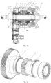
- the present application provides a bogie, including a frame 100, wheelsets 108, an axle 110 and the above-mentioned traveling gear structure for the rack vehicle.
- the axle 110 is connected to the frame 100; the wheelsets 108 are provided at both ends of the axle 110; the traveling gear structure is disposed between the two wheelsets 108 and connected to the axle 110.
- the bogie further includes: a first power box 70, a second support bracket 71, a first axle sleeve 77, a traveling gear and a first adjusting assembly 80, where the traveling gear is the above-mentioned traveling gear structure.
- the first power box 70 and the second support bracket 71 are disposed at intervals and the axle 110 penetrates through the first power box 70 and the second support bracket 71 in sequence.
- the wheelsets 108 are provided at both ends of the axle 110; the first axle sleeve 77 is sleeved outside the axle 110, penetrates through the second support bracket 71, and is matched rotatably with the second support bracket 71.
- the traveling gears are connected with the first axle sleeve 77 inside the second support bracket 71, and a part of the traveling gears stretches out of the second support bracket 71 along the radial direction of the first axle sleeve 77 to mesh with the rack provided on the ground.
- the first adjusting assembly 80 is rotatably sleeved outside the first axle sleeve 77 and connected with the second support bracket 71 to adjust the relative position between the traveling gears and the wheelsets 108.
- the present embodiment provides an implementation of a drive device.
- a problem of matching the height of the traveling gears with the worn wheelset 108 after the wheelset 108 is worn is solved and unsprung mass is reduced, and it is easier to adjust the relative position between the traveling gear structure and the wheelset 108.
- the first adjusting assembly 80 includes: a first bearing A 81, a second bearing A 82 and a second eccentric wheel 83.
- the first bearing A 81 and the second bearing A 82 are disposed at intervals along the axial direction of the first axle sleeve 77.
- the second eccentric wheel 83 is matched with an inner ring of the first bearing A 81 and an outer ring of the second bearing A 82 respectively; where the outer ring of the first bearing A 81 is matched with the inner ring of the traveling gear structure; and the inner ring of the second bearing A 82 is matched with the first axle sleeve 77.
- the present embodiment provides an implementation of the first bearing A81, the second bearing A 82 and the second eccentric wheel 83.
- the second eccentric wheel 83 is connected to the second support bracket 71 to reduce the unsprung mass.
- the second eccentric wheel 83 is disposed close to the traveling gear. By adjusting the second eccentric wheel 83 on one side, the relative position between the traveling gear and the wheelsets 108 can be adjusted, which solves the problem that the eccentric structure needs to be adjusted from both sides to adjust the relative position balance between the traveling gear and the wheelset 108 in the related art.
- the second eccentric wheel 83 can be connected rotatably to both the first axle sleeve 77 and the traveling gear.
- the centers of circles of the traveling gear and the wheelset 108 can be first disposed at the same height, and a position of traveling gear relative to the wheelset 108 can be fixed through corresponding positioning structures.
- the wheelset 108 is worn, and the height of the traveling gear is also reduced simultaneously.
- the tooth top of the rack on the track will not be lowered relative to the rail surface. If the relative height between the traveling gear and the wheelset 108 is not adjusted, greater impact, vibration and noise problems will occur during driving, which results in greater safety risk in the long term.
- the second eccentric wheel 83 rotates around the center of the first axle sleeve 77, it drives the traveling gear on the first axle sleeve 77 to rise relative to the wheelsets 108, and the height of the traveling gear relative to the wheelset 108 is changed.
- the wheelsets 108 can be used continuously, and the service life of the wheelset 108 can be prolonged by raising the traveling gear multiple times.
- the height of the traveling gear can be adjusted through the second eccentric wheel 83 on one side, which avoids the problem that the second eccentric wheel 83 is simultaneously adjusted along both sides of the axle 110 to ensure the adjustment stability of the traveling gear in the related art.
- the first adjusting assembly 80 further includes: a first adjusting disc 84, the first adjusting disc 84 is connected to the second eccentric wheel 83 to adjust a steering of the second eccentric wheel 83 through the first adjusting disc 84.
- the present embodiment provides an implementation of the first adjusting disc 84.
- the second eccentric wheel 83 is more conveniently adjusted.
- an inner ring of the first adjusting disc 84 is provided with inner ring gears
- an outer ring of the second eccentric wheel 83 is provided with outer ring gears corresponding to the inner ring gears of the first adjusting disc 84.
- the first adjusting disc 84 is meshed with the second eccentric wheel 83 through the inner ring gears and outer ring gears.
- the rotation angle of the second eccentric wheel 83 can be adjusted by rotating the first adjusting disc 84.
- the first adjusting disc 84 is provided with corresponding adjusting holes to conventionally adjusting the rotation angle of the first adjusting disc 84 through the adjusting holes.
- the outer ring of the first adjusting disc 84 is provided with corresponding cogging to conventionally apply force from the circumferential direction of the first adjusting disc 84 for adjusting the rotation angle of the first adjusting disc 84.
- two first adjusting assemblies 80 are symmetrically disposed on both sides of the traveling gear along the axial direction of the first axle sleeve 77.
- the present embodiment provides an implementation of setting the number of the first adjusting assemblies 80. By disposing the first adjusting assemblies 80 on both sides of the traveling gear, the second eccentric wheel 83 can be adjusted from either side.
- the bogie further includes: a first brake disc 47, a first brake cylinder 75 and a first brake caliper 76.
- the first brake disc 47 is connected to the axle 110 and is disposed between the second support bracket 71 and the wheelset 108.
- the first brake cylinder 75 is connected to the second support bracket 71 and the first brake caliper 76 is connected to the first brake cylinder 75 and is disposed corresponding to the first brake disc 47.
- the first brake cylinder 75 drives the first brake caliper 76 to move for enabling the first brake caliper 76 to clamp the first brake disc 47.
- the present embodiment provides an implementation of the first brake disc 47, the first brake cylinder 75, and the first brake caliper 76 and the traveling gear is braked by providing the first brake disc 47, the first brake cylinder 75 and the first brake caliper 76.
- the first brake cylinder 75 is connected to the second support bracket 71 to reduce the volume of the braking device and reduce the axial occupation space, the height of the first power box 70 and the second support bracket 71 and the braking device is used to solve the space limitation problem of narrow rails.
- the first brake disc 47 is connected to the axle 110 to form a disc brake structure, which improves the reliability of braking.
- the present application provides a drive device for a rack vehicle, including: a second power box 210, a support bracket 220, a second axle sleeve 250, a traveling gear 660 and a second adjusting assembly 770.
- the second power box 210 and the support bracket 220 are disposed at intervals; an axle 110 is provided between the second power box 210 and the support bracket 220, and wheelsets are provided at both ends of the axle 110.
- the second axle sleeve 250 is sleeved outside the axle 110, penetrates through the support bracket 220, and is rotatably matched with the support bracket 220.
- the traveling gear 660 is connected to the second axle sleeve 250 inside the support bracket 220, and a part of the traveling gears 660 extends out of the support bracket 220 along the radial direction of the second axle sleeve 250 to mesh with a rack provided on the ground.
- the second adjusting assembly 770 is rotatably sleeved outside the second axle sleeve 250 and connected with the support bracket 220 to adjust the relative position between the traveling gears 660 and the wheelset 108.
- the present application provides the drive device for the rack vehicle to solve the defect that the worn wheelset 108 is unable to be meshed with the traveling gears 660 after the wheelset 108 is gradually worn with use and the wear of the wheelset 108 reaches a certain level since the meshing of the gear and the rack has strict center distance requirements due to the characteristics of gear and rack transmission.
- the second adjusting assembly 770 By connecting the second adjusting assembly 770 to the second axle sleeve 250 and the support bracket 220, the problem of matching the height of the traveling gear 660 and the worn wheelset 108 is solved, the unsprung mass is reduced at the same time, and it is easier to adjust the relative position between the traveling gears 660 and the wheelset 108.
- the second adjusting assembly 770 includes: a first bearing B 771, a second bearing B 72, and a third eccentric wheel 73.
- the first bearing B 771 and the second bearing B 72 are disposed at intervals along the axial direction of the second axle sleeve 250, and the third eccentric wheel 73 is matched with an inner ring of the first bearing B 771 and an outer ring of the second bearing B 72 respectively.
- an outer ring of the first bearing B 771 is matched with an inner ring of the traveling gear 660; and an inner ring of the second bearing B 72 is matched with the second axle sleeve 250.
- the present embodiment provides an implementation of the first bearing B 771, the second bearing B 72, and the third eccentric wheel 73.
- the third eccentric wheel 73 is connected to the support bracket 220, which reduces the unsprung mass.
- the third eccentric wheel 73 is disposed close to the traveling gear 660.
- the relative position between the traveling gear 660 and the wheelsets 108 can be adjusted, which solves the problem that the eccentric structure needs to be adjusted from both sides to adjust the relative position balance between the traveling gear 660 and the wheelset 108 in the related art.
- the third eccentric wheel 73 can be connected rotatably to both the second axle sleeve 250 and the traveling gear 660.
- the centers of circles of the traveling gear 660 and the wheelset 108 can be first disposed at the same height, and a position of traveling gear 660 relative to the wheelset 108 can be fixed through corresponding positioning structures.
- the wheelset 108 wears, and the height of the traveling gear 660 is also reduced simultaneously.
- the tooth top of the rack on the track will not be lowered relative to the rail surface. If the relative height between the traveling gear 660 and the wheelset 108 is not adjusted, greater impact, vibration and noise problems will occur during driving, which results in greater safety risk in the long term.
- the third eccentric wheel 73 rotates around the center of the second axle sleeve 250, it drives the traveling gear 660 on the second axle sleeve 250 to rise relative to the wheelsets 108, and the height of the traveling gear 660 relative to the wheelsets 108 is changed.
- the wheelset 108 can be used continuously, and the service life of the wheelset 108 can be prolonged by raising the traveling gear 660 multiple times.
- the height of the traveling gear 660 can be adjusted through the third eccentric wheel 73 on one side, which avoids the problem that the third eccentric wheel 73 is simultaneously adjusted along both sides of the axle 110 to ensure the adjustment stability of the traveling gear 660 in the related art.
- the second adjusting assembly 770 further includes: a second adjusting disc 74, the second adjusting disc 74 is connected to the third eccentric wheel 73 to adjust a steering of the third eccentric wheel 73 through the second adjusting disc 74.
- the present embodiment provides an implementation of the second adjusting disc 74.
- the third eccentric wheel 73 is more conveniently adjusted.
- an inner ring of the second adjusting disc 74 is provided with inner ring gears
- an outer ring of the third eccentric wheel 73 is provided with outer ring gears corresponding to the inner ring gears of the second adjusting disc 74.
- the second adjusting disc 74 is meshed with the third eccentric wheel 73 through the inner ring gears and outer ring gears.
- the rotation angle of the third eccentric wheel 73 can be adjusted by rotating the second adjusting disc 74.
- the second adjusting disc 74 is provided with corresponding adjusting holes to conventionally adjusting the rotation angle of the second adjusting disc 74 through the adjusting holes.
- the outer ring of the second adjusting disc 74 is provided with corresponding cogging to conventionally apply force from the circumferential direction of the second adjusting disc 74 for adjusting the rotation angle of the second adjusting disc 74.
- two second adjusting assemblies 770 are symmetrically disposed on both sides of the traveling gear 660 along the axial direction of the second axle sleeve 250.
- the present embodiment provides an implementation in which the number of second adjusting assemblies 770 is set. By disposing the second adjusting assemblies 770 on both sides of the traveling gear 660, the second eccentric wheel 83 can be adjusted from either side.
- the drive device further includes: a second brake disc 880, a second brake cylinder 881 and a second brake caliper 882.
- the second brake disc 880 is connected to the axle 110 and is disposed between the support frame 220 and the wheelset 108.
- the second brake cylinder 881 is connected to the support bracket 220; and the second brake caliper 882 is connected to the second brake cylinder 881 and is disposed corresponding to the second brake disc 880.
- the second brake cylinder 881 drives the second brake caliper 882 to move for enabling the second brake caliper 882 to clamp the second brake disc 880.
- the present embodiment provides an implementation of the second brake disc 880, the second brake cylinder 881 and the second brake caliper 882, and the traveling gear 660 is braked by providing the second brake disc 880, the second brake cylinder 881 and the second brake clamp 882.
- the second brake cylinder 881 is connected to the support bracket 220 to reduce the volume of the braking device and reduce the axial occupation space, the height of the second power box 210 and the support bracket 220 and the braking device is used to solve the space limitation problem of narrow rails.
- the second brake disc 880 is connected to the axle 110 to form a disc brake structure, which improves the reliability of braking.
- the traveling gear 660 includes: a second toothed ring portion 661, a second transmission portion 662 and a plurality of second elastic portions 63; an outer ring of the second toothed ring portion 661 is provided with second outer gear teeth 611, and the second outer gear teeth 611 are meshed with a rack; an outer ring of the second transmission portion 662 is matched with an inner ring of the second toothed ring portion 661; inner ring gears of the second transmission portion 662 are meshed with a second transmission gear 51 on the second axle sleeve 250; the plurality of second elastic portions 63 are evenly distributed on the side of the second toothed ring portion 661 along the circumferential direction, and are respectively connected to the second toothed ring portion 661 and the second transmission portion 662.
- the present embodiment provides an implementation of the second toothed ring portion 661, the second transmission portion 662 and the second elastic portions 63.
- the plurality of second elastic portions 63 form an elastic assembly along the circumferential direction of the second toothed ring portion 661; the two elastic assemblies are symmetrically disposed on both sides of the second toothed ring portion 661 along the axial direction.
- the second elastic portions 63 symmetrically on both sides of the second toothed ring portion 661 along the axial direction of the second axle sleeve 250, and disposing the plurality of second elastic portions 63 annularly, the capability of the traveling gear 660 to transmit torque is improved while an eccentric load of the traveling gear 660 is decreased, and the impact of the gear meshing process is reduced, a large torque of the traveling gear 660 is transmitted and needs of the rack vehicle are satisfied.
- disposing the second elastic portions 63 increases the damping of the traveling gear 660, reduces noise caused by meshing between the gear and the rack, reduces the vibration experienced by the rack vehicle during driving, and improves the riding comfort.
- the two groups of elastic assemblies are symmetrically disposed, which solves the need for the traveling gear 660 to transmit very high torque when the rack vehicle runs on a large slope.
- each elastic assembly includes a plurality of second elastic portions 63 disposed annularly. This arrangement improves the uniformity of the load and impacts and vibrations experienced by the traveling gears 660 can be absorbed well.
- an elastic assembly composed of a plurality of second elastic portions 63 is disposed on the side of the second toothed ring portion 661, radial space is freed and a larger transmission structure is connected internally, which improves the performance of a transmission system.
- the drive device further includes a third bushing 90.
- the third bushing 90 is disposed between the inner ring of the second toothed ring portion 661 and the outer ring of the second transmission portion 662 to decrease a friction coefficient between the second toothed ring portion 661 and the second transmission portion 662.
- the third bushing 90 is disposed to decrease the friction coefficient and solve the friction problem caused by relative displacement between the second toothed ring portion 661 and the second transmission portion 662.
- the third bushing 90 is made of a self-lubricating material.
- the third bushing 90 is made of a carbon-based material.
- the third bushing 90 is a self-lubricating bushing.
- the traveling gear 660 further includes: a plurality of first mounting bases B 64 and a plurality of second mounting bases B 65.
- the first mounting bases B 64 are evenly distributed on a side of the second toothed ring portion 661 along the circumferential direction; the second mounting bases B 65 are evenly distributed on the outer ring of the second transmission portion 662 along the circumferential direction, and the first mounting bases B 64 and the second mounting bases B 65 are disposed staggeredly.
- the second elastic portions 63 are detachably connected to the adjacent first mounting base B 64 and second mounting base B 65 respectively.
- the present embodiment provides an implementation of the first mounting bases B 64 and the second mounting bases B 65.
- the second elastic portions 63 are mounted and positioned at the side of the second toothed ring portion 10.
- first mounting bases B 64 and the second mounting bases B65 are disposed staggeredly on the side of the second toothed ring portion 661, and the first mounting bases B 64 and the second mounting bases B 65 are provided with corresponding mounting holes.
- the second elastic portions 63 are respectively connected to the first mounting base B 64 and the second mounting base B 65 through screws or other connecting components.
- the second transmission portion 662 includes: a second transmission connecting base 621, a second transmission supporting base 622 and a plurality of second connecting units 623.
- a second boss 624 is provided on a first side of the second transmission connecting base 621 and an inner ring of the second boss 624 is provided with inner ring gears that are meshed with the second transmission gear 51.
- the second transmission supporting base 622 is insertedly matched with the second transmission connecting base 621 through the second boss 624.
- the plurality of second connecting units 623 are provided on a matching surface of the second transmission connecting base 621 and the second transmission supporting base 622 to detachably connect the second transmission connecting base 621 and the second transmission supporting base 622.
- the plurality of second mounting bases B 65 are evenly distributed on the outer rings of the second transmission connecting base 621 and the first transmission supporting base 622 along the circumferential direction.
- the present embodiment provides an implementation of the second transmission connecting base 621, the second transmission supporting base 622 and the second connecting units 623.
- the second transmission portion 662 is more conveniently connected to the second toothed ring portion 661.
- the inner ring gears provided on the inner ring of the second boss 624 is meshed with the second transmission gear 51 to provide the transmission connection between the traveling gear 660 and the second axle sleeve 250, which facilitates the installation and removal of the traveling gear 660.
- the matching surface of second transmission connecting base 621 and the second transmission supporting base 622 is provided with corresponding mounting holes or screw holes, and the connectors are matched with the mounting holes or screw holes to connect the second transmission connecting base 621 to the second transmission supporting base 622.
- the present application does not describe the connection in too much detail. Please refer to the accompanying drawings and settings in related fields.
- each of the second mounting bases B65 includes: a first sub-mounting base B 651 and a second sub-mounting base B 652.
- the plurality of first sub-mounting bases B651 are evenly distributed circumferentially on the outer ring of the second transmission connecting base 621, and are disposed close to a second side of the second transmission connecting base 621 relative to the second boss 624;
- the plurality of second sub-mounting base B 652 are evenly distributed circumferentially on the outer ring of the second transmission supporting base 622 and are disposed close to a side of the second transmission supporting base 622 away from the second transmission connecting base 621.
- the present embodiment provides an implementation of the first sub-mounting base B 651 and the second sub-mounting base B 652.
- the second elastic portions 63 are disposed on both sides of the second toothed ring portion 661.
- first mounting base B 64 and the first sub-mounting base B 651 are staggeredly disposed on a first side of the second toothed ring portion 661
- first mounting base B 64 and the second sub-mounting base B652 are staggeredly disposed on a second side of the second toothed ring portion 661, and connection and installation positions of the second elastic portions 63 on both sides of the second toothed ring portion 661 are formed.
- the first sub-mounting base B 651 and the second sub-mounting base B 652 are respectively provided with corresponding screw holes to detachably connect the second elastic portions 63 and the first mounting base B64, the first sub-mounting base B651, the first mounting base B 64 and second sub-mounting base B 652 adjacent to the second elastic portions 63.
- At least part of the second connecting units 623 are shear-resistant pins.
- a part of the second connecting units 623 are connected threadedly to the second transmission connecting base 621 and the second transmission supporting base 622 respectively, to detachably connect the second transmission connecting base 621 and the second transmission supporting base 622.
- a part of the second connecting units 623 are insertedly matched with the second transmission connecting base 621 and the second transmission supporting base 622 respectively in an interference-fit or transition fit form to provide second transmission connecting base 621 and the second transmission supporting base 622 with shear resistance.
- each of the second elastic portions 63 includes: a first mounting plate B 631, a second mounting plate B 632 and a second elastomer 633.
- the first mounting plate B 631 and the second mounting plate B 632 are connected to form a mounting assembly which is L-shaped; two mounting assemblies are disposed at intervals and the second elastomer 633 is disposed between the two mounting assemblies.
- the first mounting plate B 631 is detachably connected to the first mounting bases B 64 or the second mounting bases B 65; the second mounting plate B 632 is connected to the second elastomer 633.
- the present embodiment provides an implementation of the first mounting plate B 631, the second mounting plate B 632 and the second elastomer 633.
- an annular elastic buffer structure composed of a plurality of second elastomers 633 is formed at a side of the second toothed ring portion 661.
- the second elastomers 633 are more conveniently disassembled and maintained.
- a certain second elastomer 633 loses elasticity or is damaged, only the independent second elastomer 633 needs to be disassembled for maintenance and replacement, and the work efficiency is improved.
- the first mounting plate B 631 is provided with corresponding through holes to correspond to the mounting holes on the first mounting base B 64 and the second mounting base B 65.
- the first mounting plate B 631 is connected to the first mounting bases B 64 or the second mounting bases B 65 through connectors such as screws and connecting pins.
- the second elastomer 633 is an elastic block made of rubber material.
- the present embodiment provides an implementation of the second elastomer 633.
- the second elastomer 633 By disposing the second elastomer 633 as an elastic block made of rubber material, the capability of the traveling gear 660 to transmit torque is improved, and at the same time, when the traveling gear 660 is subjected to a certain eccentric load or impact, the eccentric load or impact can be effectively absorbed by the second elastomer 633.
Landscapes
- Engineering & Computer Science (AREA)
- Mechanical Engineering (AREA)
- Transportation (AREA)
- Chemical & Material Sciences (AREA)
- Combustion & Propulsion (AREA)
- Seats For Vehicles (AREA)
- Vibration Prevention Devices (AREA)
- Transmission Devices (AREA)
Abstract
Description
- The present application claims priorities to
Chinese patent application No. 202210474938.1 filed on April 29, 2022 Chinese patent application No. 202210514231.9 filed on May 11, 2022 Chinese patent application No. 202210514234.2 filed on May 11, 2022 - The present application relates to the field of rack vehicles, and provides a bogie, a vehicle body and a rack vehicle.
- A rack railway is very suitable as a sightseeing route in mountainous areas or tourist attractions due to strong climbing capability, good safety and low construction costs. Especially when environmental protection restrictions have become more stringent recent years in China, the length of rack railway decreases greatly under the same climbing conditions compared with ordinary railway lines, thus, the environment of tourist attractions and areas with high environmental protection requirements is less impacted and the vegetation and geological environment along the route are effectively protected. However, the rack railway vehicles are less stable and comfortable since the rack rail adopted by the rack railway. After traveling gears of the rack vehicle wear, a center distance between the traveling gears and a rack will gradually decrease. However, due to the characteristics of the gear-rack transmission, it cannot adapt to the large amount of wheel wear. After wheels wear, the traveling gears or wheels need to be replaced, which results in higher maintenance costs.
- An embodiment of the present application provides a bogie, which solves the defects of poor stability and comfort of a rack railway vehicle in related art and improves the stability and comfort of the rack railway vehicle.
- An embodiment of the present application provides a bogie, including:
- a frame, including a pair of side beams, a pair of cross beams and a pair of end beams, where both ends of the pair of cross beams are respectively connected between the pair of side beams, and the pair of end beams are respectively connected to both ends of the pair of side beams;
- two wheelsets, rotatably mounted on the frame through axles and respectively located in an area surrounded by the end beams, cross beams adjacent to the end beams and the pair of side beams;
- a pair of traveling gears, respectively mounted on the axle through an eccentric device and disposed along a longitudinal axis of the frame; and
- a pair of drive members, respectively mounted on the cross beams, and respectively in transmission connection with the pair of traveling gears through transmission devices, where the transmission devices are respectively provided on sides away from the pair of traveling gears along a transverse direction of the frame.
- In the bogie provided by the embodiment of the present application, the pair of traveling gears and the pair of drive members are provided, and the pair of drive members are connected to the pair of traveling gears through the transmission devices, and the transmission devices are respectively provided on sides away from the pair of traveling gears along the transverse direction of the frame, the drive members, the transmission devices, and the traveling gears form a Z-shaped structure in sequence, which makes the traveling structure of the bogie more stable and improves the operating stability of the vehicle. By mounting the pair of traveling gears on the axle through the eccentric device, it is only necessary to adjust the position of the traveling gears relative to a meter-gauge track without changing the position structure of a drive device during the process of adjusting the height of the traveling gears. Through the above adjustments, the height of the traveling gears can be precisely adjusted, ensuring accurate meshing of the traveling gears with the meter-gauge track. Therefore, the bogie also has the advantages of simple structure, convenient maintenance and low maintenance costs.
- According to an embodiment of the present application, the eccentric device includes:
- a first support bearing, having an inner ring sleeved on the axle;
- a first eccentric wheel, sleeved on an outer ring of the first support bearing and eccentrically provided with respect to the axle, where a position of the first eccentric wheel relative to the first support bearing is locked through a locking mechanism; and
- a second support bearing, having an inner ring sleeved outside the first eccentric wheel, where the traveling gears sleeve an outer ring of the second support bearing.
- In an embodiment of the present application, the bogie further includes a first support bracket mounted on the frame, a plurality of mounting holes for mounting the first support bearing are provided on the first support bracket, and a plurality of first positioning holes are provided on an end surface of the mounting holes along a circumferential direction of the mounting holes;
the locking mechanism includes: - an adjusting ring, connected to an outer circumference of the first eccentric wheel, where a plurality of second positioning holes are provided on an end surface of the adjusting ring along a circumferential direction of the adjusting ring; and
- a locking member, penetrating through the first positioning holes and the second positioning holes to lock a position of the first eccentric wheel relative to the first support bracket.
- According to an embodiment of the present application, a first bushing is further sleeved on the outer circumference of the first eccentric wheel, and the first bushing is configured to reduce a friction between an outer circumference of the first eccentric wheel and an inner wall of the mounting holes.
- According to an embodiment of the present application, the number of the first eccentric wheel is two, and a synchronization block is provided between the two first eccentric wheels.
- According to an embodiment of the present application, a projection of the wheelsets is located within a projection of the frame in a plane parallel to a meter-gauge track.
- According to an embodiment of the present application, the bogie further includes a secondary damping device, where the secondary damping device includes a bottom plate connected to a top of the side beams and an air spring mounted on the bottom plate, and the air spring is conical in a direction from the bottom plate away from the side beams.
- According to an embodiment of the present application, the bogie further includes an anti-roll device mounted on each of the side beams, and the anti-roll device includes:
- a bearing seat, mounted at a bottom of each of the side beams;
- a torsion bar shaft, mounted in the bearing seat; and
- an anti-roll torsion bar, connected between the torsion bar shaft and a vehicle body, where a ball hinge structure is provided at an end of the anti-roll torsion bar connected to the vehicle body.
- According to an embodiment of the present application, the bogie further includes a first braking device and a second braking device,
- the first braking device includes:
- a mounting bracket, mounted on the side beams;
- brake shoes, provided on the mounting bracket and opposite to a tread of the wheelsets;
- the second braking device includes:
- a brake disc, disposed coaxially with each of the wheelsets;
- two friction rings, respectively provided on opposite sides of the wheelset, where a heat dissipation structure is provided between the two friction rings; and
- a brake cylinder, provided on the side beam and driving the two friction rings to move relative to the brake disc.
- According to an embodiment of the present application, the bogie further includes a rim lubricating device, mounted on each of the side beams and facing the two traveling gears respectively.
- An embodiment of the present application provides a vehicle body, including the above-mentioned bogie, which is mounted below the vehicle body.
- In the vehicle body provided by the embodiment of the present application, by providing the above-mentioned bogie, the stability of the vehicle body can be improved and the shaking and vibration amplitude of the vehicle body can be reduced.
- An embodiment of the present application provides a rack vehicle, including the above-mentioned bogie or the above-mentioned vehicle body.
- In the rack vehicle provided by the third embodiment of the present application, by providing the above-mentioned bogie or vehicle body, it can not only improve the riding experience of passengers, but also adapt to rack railways of different specifications.
- According to an embodiment of the present application, the rack vehicle further includes a traveling gear structure for the rack vehicle;
- the traveling gear structure includes a first toothed ring portion, a first transmission portion and a plurality of first elastic portions;
- an outer ring of the first toothed ring portion is provided with a first outer gear teeth, and the first outer gear teeth are meshed with a rack provided on the ground;
- an outer ring of the first transmission portion is matched with an inner ring of the first toothed ring portion; and
- the plurality of first elastic portions are evenly distributed on the side of the first toothed ring portion along the circumferential direction, and are respectively connected to the first toothed ring portion and the first transmission portion.
- According to an embodiment of the present application, the plurality of first elastic portions form an elastic assembly along the circumferential direction of the first toothed ring portion; and
two elastic assemblies are symmetrically disposed on both sides of the first toothed ring portion along an axial direction. - The present embodiment provides an implementation of the first elastic portion, by symmetrically disposing the first elastic portions on both sides of the first toothed ring portion along the axial direction of a first axle sleeve, and disposing the plurality of first elastic portions annularly, the capability of the traveling gear to transmit torque is improved while an eccentric load of the traveling gear is decreased, and the impact of the gear meshing process is reduced, a large torque of the traveling gear is transmitted and needs of the rack vehicle are satisfied.
- According to an embodiment of the present application, the traveling gear structure further includes: a second bushing, the second bushing is disposed between the inner ring of the first toothed ring portion and the outer ring of the first transmission portion to decrease a friction coefficient between the first toothed ring portion and the first transmission portion.
- The present embodiment provides an implementation of the second bushing. By disposing the second bushing, the friction coefficient is decreased, and a friction problem caused by relative displacement between the first toothed ring portion and the first transmission portion is solved.
- According to an embodiment of the present application, the traveling gear structure further includes: a plurality of first mounting bases A and a plurality of second mounting bases A;
- the first mounting bases A are evenly distributed on a side of the first toothed ring portion along the circumferential direction;
- the second mounting bases A are evenly distributed on the outer ring of the first transmission portion along the circumferential direction, and the first mounting bases A and the second mounting bases A are disposed staggeredly; and
- the first elastic portions are detachably connected to the adjacent first mounting bases A and the second mounting bases A, respectively.
- The present embodiment provides an implementation of the first mounting bases A and the second mounting bases A. By disposing the first mounting bases A and the second mounting bases A, the first elastic portions are mounted and positioned at the side of the first toothed ring portion.
- According to an embodiment of the present application, the first transmission portion includes: a first transmission connecting base, a first transmission supporting base and a plurality of first connecting units;
- a first boss is provided on a first side of the first transmission connecting base, and an inner ring of the first boss is provided with inner ring gears;
- the first transmission supporting base is insertedly matched with the first transmission connecting base through the first boss;
- the plurality of first connecting units are provided on a matching surface of the first transmission connecting base and the first transmission supporting base to detachably connect the first transmission connecting base and the first transmission supporting base; and
- the plurality of second mounting bases A are evenly distributed on the outer rings of the first transmission connecting base and the first transmission supporting base along the circumferential direction.
- The present embodiment provides an implementation of the first transmission connecting base, the first transmission supporting base and the first connecting units. By disposing the first transmission connecting base, the first transmission supporting base and the first connecting units, the connection between the first transmission portion and the first toothed ring portion is more convenient.
- It should be noted that the first toothed ring portion and the first transmission portion are connected through the first elastic portions.
- Furthermore, the inner ring gears provided on the inner ring of the first boss provides the transmission connection between the traveling gear and an external gear corresponding thereto, which facilitates the installation and disassembly of the traveling gear.
- According to an embodiment of the present application, each of the second mounting bases A includes: a plurality of first sub-mounting bases A and a plurality of second sub-mounting bases A;
- the first sub-mounting bases A are evenly distributed circumferentially on the outer ring of the first transmission connecting base, and are disposed close to a second side of the first transmission connecting base relative to the first boss; and
- the plurality of second sub-mounting bases A are evenly distributed circumferentially on the outer ring of the first transmission supporting base, and are disposed close to a first side of the first transmission supporting base away from the first transmission connecting base.
- The present embodiment provides an implementation of the first sub-mounting bases A and the second sub-mounting bases A. By disposing the plurality of first sub-mounting bases A circumferentially on the second side of the first transmission connecting base, the plurality of second sub-mounting bases A circumferentially on the first side of the first transmission supporting base, the first elastic portions are disposed on both sides of the first toothed ring portion.
- It should be noted that the first mounting bases A and the first sub-mounting bases A are disposed staggeredly on the first side of the first toothed ring portion, and the first mounting bases A and the second sub-mounting bases A are disposed staggeredly on the second side of the first toothed ring portion, the connection and installation positions of the first elastic portion on both sides of the first toothed ring portion are formed.
- According to an embodiment of the present application, at least part of the first connecting units are shear-resistant pins.
- The present embodiment provides an implementation of the first connecting units. By configuring part of the first connecting unit as shear-resistant pins, the stability of the connection between the first transmission connecting base and the first transmission supporting base is improved.
- According to an embodiment of the present application, each of the first elastic portions includes: a first mounting plate A, a second mounting plate A and a first elastomer;
- the first mounting plate A and the second mounting plate A are connected to form a mounting assembly which is L-shaped;
- two mounting assemblies are disposed at intervals;
- the first elastomer is disposed between the two mounting assemblies;
- the first mounting plate A is detachably connected to the first mounting bases A or the second mounting bases A; and
- the second mounting plate A is connected to the first elastomer.
- The present embodiment provides an implementation of the first mounting plate A, the second mounting plate A, and the first elastomer. By disposing the first mounting plate A, the second mounting plate A, and the first elastomer, an annular elastic buffer structure composed of a plurality of first elastomers is formed on a side of the first toothed ring portion.
- Furthermore, the arrangement of the first mounting plates A and the second mounting plates A also enables the first elastomers to be disassembled and maintained more conveniently. When a certain first elastomer loses elasticity or is damaged, only the independent first elastomer needs to be disassembled for maintenance and replacement, which improves work efficiency.
- According to an embodiment of the present application, the first elastomer is an elastic block made of a rubber material.
- The present embodiment provides an implementation of the first elastomer. By configuring the first elastomer as an elastic block made of the rubber material, the capability of the traveling gear to transmit torque is improved, and at the same time, when the traveling gear is subjected to a certain eccentric load or impact, the eccentric load or impact can be effectively absorbed by the first elastomer.
- According to an embodiment of the present application, the rack vehicle further includes a drive device for the rack vehicle;
- the drive device includes a second power box, a support bracket, a second axle sleeve, traveling gears and a second adjusting assembly;
- the second power box and the support bracket are disposed at intervals;
- an axle is provided between the second power box and the support bracket, and wheelsets are provided at both ends of the axle;
- the second axle sleeve is sleeved outside the axle, penetrates through the support bracket, and is rotatably matched with the support bracket;
- the traveling gears are connected to the second axle sleeve inside the support bracket, and a part of the traveling gears extends out of the support bracket along the radial direction of the second axle sleeve to mesh with a rack provided on the ground; and
- the second adjusting assembly is rotatably sleeved outside the second axle sleeve and connected with the support bracket to adjust the relative position between the traveling gears and the wheelset.
- According to an embodiment of the present application, the second adjusting assembly includes: a first bearing B, a second bearing B and a third eccentric wheel;
- the first bearing B and the second bearing B are disposed at intervals along the axial direction of the second axle sleeve;
- the third eccentric wheel is matched with an inner ring of the first bearing B and an outer ring of the second bearing B respectively;
- an outer ring of the first bearing B is matched with an inner ring of the traveling gear; and
- an inner ring of the second bearing B is matched with the second axle sleeve.
- According to an embodiment of the present application, the second adjusting assembly further includes: a second adjusting disc, the second adjusting disc is connected to the third eccentric wheel to adjust a steering of the third eccentric wheel through the second adjusting disc.
- According to an embodiment of the present application, the two second adjusting assemblies are symmetrically disposed on both sides of the traveling gear along the axial direction of the second axle sleeve.
- According to an embodiment of the present application, the drive device further includes: a second brake disc, a second brake cylinder and a second brake caliper;
- the second brake disc is connected to the axle and is disposed between the support bracket and the wheelsets;
- the second brake cylinder is connected to the support bracket;
- the second brake caliper is connected to the second brake cylinder and is disposed corresponding to the second brake disc; and
- the second brake cylinder drives the second brake caliper to make the second brake caliper clamp the second brake disc.
- According to an embodiment of the present application, the traveling gear includes: a second toothed ring portion, a second transmission portion and a plurality of second elastic portions;
- an outer ring of the second toothed ring portion is provided with second outer gear teeth, and the second outer gear teeth are meshed with the rack;
- an outer ring of the second transmission portion is matched with an inner ring of the second toothed ring portion, and inner ring gears of the second transmission portion are meshed with a second transmission gear on the second axle sleeve; and
- the plurality of second elastic portions are evenly distributed on the side of the second toothed ring portion along the circumferential direction, and are respectively connected to the second toothed ring portion and the second transmission portion.
- According to an embodiment of the present application, the traveling gear further includes: a plurality of first mounting bases B and a plurality of second mounting bases B;
- the first mounting bases B are evenly distributed on a side of the second toothed ring portion along the circumferential direction;
- the second mounting bases B are evenly distributed on the outer ring of the second transmission portion along the circumferential direction, and the first mounting bases B and the second mounting bases B are disposed staggeredly; and
- the second elastic portions are detachably connected to the adjacent first mounting bases B and the second mounting bases B, respectively.
- According to an embodiment of the present application, the second transmission portion includes: a second transmission connecting base, a second transmission supporting base and a plurality of second connecting units;
- a second boss is provided on a first side of the second transmission connecting base, and an inner ring of the second boss is provided with inner ring gears meshed with the second transmission gear;
- the second transmission supporting base is insertedly matched with the second transmission connecting base through the second boss;
- the plurality of second connecting units are provided on a matching surface of the second transmission connecting base and the second transmission supporting base to detachably connect the second transmission connecting base and the second transmission supporting base; and
- the plurality of second mounting bases B are evenly distributed on the outer rings of the second transmission connecting base and the second transmission supporting base along the circumferential direction.
- According to an embodiment of the present application, each of the second mounting bases B includes: a plurality of first sub-mounting bases B and a plurality of second sub-mounting bases B;
- the first sub-mounting bases B are evenly distributed circumferentially on the outer ring of the second transmission connecting base, and are disposed close to a second side of the second transmission connecting base relative to the second boss; and
- the plurality of second sub-mounting bases B are evenly distributed circumferentially on the outer ring of the second transmission supporting base, and are disposed close to a first side of the second transmission supporting base away from the second transmission connecting base.
- According to an embodiment of the present application, each of the second elastic portions includes: a first mounting plate B, a second mounting plate B and a second elastomer;
- the first mounting plate B and the second mounting plate B are connected to form a mounting assembly which is L-shaped;
- two mounting assemblies are disposed at intervals;
- the second elastomer is disposed between the two mounting assemblies;
- the first mounting plate B is detachably connected to the first mounting bases B or the second mounting bases B; and
- the second mounting plate B is connected to the second elastomer.
- One or more of the above solutions in the embodiments of the present application have at least one of the following effects.
- In the bogie provided by the embodiment of the present application, the pair of traveling gears and the pair of drive members are provided, and the pair of drive members are connected to the pair of traveling gears through the transmission devices, and the transmission devices are respectively provided on sides away from the pair of traveling gears along a transverse direction of the frame, thus, the drive members, the transmission devices, and the traveling gears form a Z-shaped structure in sequence, which makes the traveling structure of the bogie more stable and improves the operating stability of the vehicle. By mounting the pair of traveling gears on the axle through the eccentric device, it is only necessary to adjust the position of the traveling gears relative to a meter-gauge track without changing the position structure of a drive device during the process of adjusting the height of the traveling gears. Through the above adjustments, the height of the traveling gears can be precisely adjusted, ensuring accurate meshing of the traveling gears with the meter-gauge track. The bogie also has the advantages of simple structure, convenient maintenance and low maintenance costs.
- In the vehicle body provided by the embodiment of the present application, by providing the above-mentioned bogie, the stability of the vehicle body can be improved and the shaking and vibration amplitude of the vehicle body can be reduced.
- In the rack vehicle provided by the third embodiment of the present application, by providing the above-mentioned bogie or vehicle body, it can not only improve the riding experience of passengers, but also adapt to rack railways of different specifications.
- To more clearly illustrate the solutions of the embodiments based on the present application or the related art, the accompanying drawings used in the description of the embodiments or the related art are briefly introduced below. It should be noted that the drawings in the following description are only some embodiments of the present application. For those of ordinary skill in the art, other drawings may be obtained based on these drawings without creative effort.
-
FIG. 1 is a schematic structural diagram of matching between a bogie and a meter-gauge track according to an embodiment of the present application; -
FIG. 2 is a schematic side view of a bogie according to an embodiment of the present application; -
FIG. 3 is a schematic top view of a bogie according to an embodiment of the present application; -
FIG. 4 is a schematic left view of a bogie according to an embodiment of the present application; -
FIG. 5 is a schematic cross-sectional view of an eccentric device according to an embodiment of the present application; -
FIG. 6 is a schematic structural diagram of the installation of a first eccentric wheel and an adjusting ring according to an embodiment of the present application; -
FIG. 7 is a schematic structural diagram of the installation of a first eccentric wheel, an adjusting ring, and a third bearing according to an embodiment of the present application; -
FIG. 8 is a schematic structural diagram of a first eccentric wheel according to an embodiment of the present application; -
FIG. 9 is a schematic structural diagram of a first bushing according to an embodiment of the present application; -
FIG. 10 is a schematic structural diagram of an adjusting ring according to an embodiment of the present application; -
FIG. 11 is a schematic structural diagram of a first support bracket according to an embodiment of the present application; -
FIG. 12 is a contour schematic structural diagram of an axis of a first eccentric wheel and an axis of an axle according to an embodiment of the present application; -
FIG. 13 is a non-contour schematic structural diagram of an axis of a first eccentric wheel and an axis of an axle according to an embodiment of the present application; -
FIG. 14 is a first schematic diagram of an assembly relationship of a traveling gear structure according to the present application; -
FIG. 15 is a second schematic diagram of an assembly relationship of a traveling gear structure according to the present application; -
FIG. 16 is a schematic cross-sectional view along line AA inFIG.15 ; -
FIG. 17 is a schematic structural diagram of a first toothed ring portion in a traveling gear structure according to the present application; -
FIG. 18 is a first structural schematic diagram of a first transmission connecting base in the traveling gear structure according to the present application; -
FIG. 19 is a second structural schematic diagram of a first transmission connecting base in a traveling gear structure according to the present application; -
FIG. 20 is a schematic structural diagram of a first transmission supporting base in a traveling gear structure according to the present application; -
FIG. 21 is a schematic diagram of the structural relationship of a first elastic portion in a traveling gear structure according to the present application; -
FIG. 22 is a first schematic diagram of an assembly relationship between a first power box, a second support bracket and a traveling gear structure in the traveling gear structure according to the present application; -
FIG. 23 is a second schematic diagram of an assembly relationship between a first power box, a second support bracket and a traveling gear structure in the traveling gear structure according to the present application; -
FIG. 24 is a third schematic diagram of an assembly relationship between a first power box, a second support bracket and a traveling gear structure in the traveling gear structure according to the present application; -
FIG. 25 is a schematic diagram of an assembly relationship between an axle, a first transmission gear and a second bearing A in the traveling gear structure according to the present application; -
FIG. 26 is a first schematic diagram of an assembly relationship of a first adjusting assembly in the traveling gear structure according to the present application; -
FIG. 27 is a second schematic diagram of an assembly relationship of a first adjusting assembly in the traveling gear structure according to the present application; -
FIG. 28 is a third schematic diagram of an assembly relationship of a first adjusting assembly in the traveling gear structure according to the present application; -
FIG. 29 is a first schematic diagram of an assembly relationship of a drive device for a rack vehicle according to the present application; -
FIG. 30 is a second schematic diagram of an assembly relationship of a drive device for a rack vehicle according to the present application; -
FIG. 31 is a third schematic diagram of an assembly relationship of a drive device for a rack vehicle according to the present application; -
FIG. 32 is a fourth schematic diagram of an assembly relationship of a drive device for a rack vehicle according to the present application; -
FIG. 33 is a fifth schematic diagram of an assembly relationship of a drive device for a rack vehicle according to the present application; -
FIG. 34 is a sixth schematic diagram of an assembly relationship of a drive device for a rack vehicle according to the present application; -
FIG. 35 is a seventh schematic diagram of an assembly relationship of a drive device for a rack vehicle according to the present application; -
FIG. 36 is a schematic structural diagram of a third eccentric wheel in a drive device for a rack vehicle according to the present application; -
FIG. 37 is a schematic structural diagram of a second adjusting disc in a drive device for a rack vehicle according to the present application; -
FIG. 38 is a first schematic diagram of an assembly relationship between a second adjusting disc and a third eccentric wheel in a drive device for a rack vehicle according to the present application; -
FIG. 39 is a second schematic diagram of an assembly relationship between a second adjusting disc and a third eccentric wheel in a drive device for a rack vehicle according to the present application; -
FIG. 40 is a first schematic diagram of an assembly relationship of traveling gears in the drive device of the rack vehicle according to the present application; -
FIG. 41 is a second schematic diagram of an assembly relationship of traveling gears in the drive device of the rack vehicle according to the present application; -
FIG. 42 is a cross-sectional view taken along line AA inFIG. 41 ; -
FIG. 43 is a schematic diagram of structural relationship of a second toothed ring portion in a drive device for a rack vehicle according to the present application; -
FIG. 44 is a first schematic diagram of structural relationship of a second transmission connecting base in a drive device for a rack vehicle according to the present application; -
FIG. 45 is a second schematic diagram of structural relationship of a second transmission connecting base in a drive device for a rack vehicle according to the present application; -
FIG. 46 is a schematic diagram of structural relationship of a second transmission supporting base in a drive device for a rack vehicle according to the present application; and -
FIG. 47 is a schematic diagram of the structural relationship of a second elastic portion in a drive device for a rack vehicle according to the present application. - 100 frame; 102 side beam; 104 cross beam; 106 end beam; 108 wheelset; 109 traveling gear; 110 axle; 111 transmission device; 112 drive member; 114 first support bearing; 116 first eccentric wheel; 118 second support bearing; 120 first support bracket; 122 mounting hole; 124 first positioning hole; 126 adjusting ring; 128 second positioning hole; 130 locking member; 132 first bushing; 134 synchronous block; 136 bottom plate; 138 air spring; 140 bearing seat; 142 anti-roll torsion bar; 144 ball hinge structure; 146 mounting bracket; 148 brake shoe; 150 second braking device; 152 rim lubricating device; 154 inner ring gear; 156 outer ring gear; 158 snap-fit slot; 160 annular positioning stage; 162 collar; 164 retaining ring; 166 mounting slot; 10 first toothed ring portion; 11 first outer gear teeth; 20 first transmission portion; 21 first transmission connecting base; 22 first transmission supporting base; 23 first connecting unit; 24 first boss; 30 first elastic portion; 31 first mounting plate A; 32 second mounting plate A; 33 first elastomer; 40 second bushing; 50 first mounting base A; 60 second mounting base A; 61 first sub-mounting base A; 62 second sub-mounting base A; 70 first power box; 71 second support bracket; 47 first brake disc; 75 first brake cylinder; 76 first brake caliper; 77 first axle sleeve; 78 first transmission gear; 80 first adjusting assembly; 81 first bearing A; 82 second bearing A; 83 second eccentric wheel; 84 first adjusting disc; 210 second power box; 220 support bracket; 250 second axle sleeve; 51 second transmission gear; 660 traveling gear; 661 second toothed ring portion; 611 second outer gear teeth; 662 second transmission portion; 621 second transmission connecting base; 622 second transmission supporting base; 623 second connecting unit; 624 second boss; 63 second elastic portion; 631 first mounting plate B; 632 second mounting plate B; 633 second elastomer; 64 first mounting bases B; 65 second mounting base B; 651 first sub-mounting base B; 652 second sub-mounting base B; 770 second adjusting assembly; 771 first bearing B; 72 second bearing B; 73 third eccentric wheel; 74 second adjusting disc; 880 second brake disc; 881 second brake cylinder; 82 second brake caliper; 90 third bushing.
- Implementations of the present application are further described in detail below with reference to the drawings and embodiments. The following embodiments are used to illustrate the present application, but are not intended to limit the scope of the present application.
- In the description of the present application, it should be noted that, the orientation or positional relations specified by terms such as "central", "longitudinal", "lateral", "up", "down", "front", "back", "left", "right", "vertical", "horizontal", "top", "bottom", "inner", "outer" and the like, are based on the orientation or positional relations shown in the drawings, which is merely for convenience of description of the present application and to simplify description, but does not indicate or imply that the stated devices or components must have a particular orientation and be constructed and operated in a particular orientation, and thus it is not to be construed as limiting the present application. Furthermore, the terms "first", "second", "third" and the like are only used for descriptive purposes and should not be construed as indicating or implying a relative importance.
- In the description of the present application, it should be noted that unless explicitly specified and defined otherwise, the terms "connected to" and "connected" shall be understood broadly, for example, it may be either fixedly connected or detachably connected, or can be integrated; it may be either mechanically connected, or electrically connected; it may be either directly connected, or indirectly connected through an intermediate medium. The specific meanings of the terms above in the present application can be understood by a person skilled in the art in accordance with specific conditions.
- In the embodiments of the present application, unless otherwise expressly specified and defined, a first feature is "on" or "under" a second feature can refer to that the first feature is directly contacted with the second feature, or the first feature is indirectly contacted with the second feature through an intermediate medium. In addition, the first feature is "on", "above" and "over" the second feature can refer to that the first feature is directly above or obliquely above the second feature, or simply refer to that the level height of the first feature is higher than that of the second feature. A first feature is "under", "below" and "beneath" a second feature can refer to that the first feature is directly below or obliquely below the second feature, or simply refer to that the level height of the first feature is lower than that of the second feature.
- In the description of this specification, description with reference to the terms "an embodiment", "some embodiments", "an example", "specific example", "some examples" and the like, refers to that specific features, structures, materials or characteristics described in combination with an embodiment or an example are included in at least an embodiment or example according to the embodiments of the present application. In this specification, schematic representations of the above terms are not necessarily directed to a same embodiment or example. Furthermore, the particular features, structures, materials or characteristics described can be combined in any suitable manner in any one or more embodiments or examples. In addition, those skilled in the art may combine the different embodiments or examples described in this specification, as well as the features of the different embodiments or examples, without conflicting each other.
- As shown in
FIG. 1 to FIG. 13 , the present application provides a bogie, including aframe 100, twowheelsets 108, a pair of travelinggears 109, and a pair ofdrive members 112. Theframe 100 includes a pair ofside beams 102, a pair ofcross beams 104 and a pair ofend beams 106 oppositely disposed, both ends of the pair ofcross beams 104 are respectively connected between the pair ofside beams 102 and the pair ofend beams 106 are respectively connected to both ends of the pair of side beams 102. Twowheelsets 108 are rotatably mounted on theframe 100 throughaxles 110 and respectively located in an area surrounded by the end beams 106, cross beams adjacent to the end beams 104 and the pair of side beams 102. The pair of travelinggears 109 are respectively mounted on theaxle 110 through an eccentric device and disposed along a longitudinal axis of theframe 100. The pair ofdrive members 112 are respectively mounted on the cross beams 104, and respectively in transmission connection with the pair of travelinggears 109 throughtransmission devices 111, and thetransmission devices 111 are respectively provided on sides away from the pair of travelinggears 109 along a transverse direction of theframe 100. - In the bogie provided by the embodiment of the present application, the pair of traveling
gears 109 and the pair ofdrive members 112 are provided, and the pair ofdrive members 112 are connected to the pair of travelinggears 109 through thetransmission devices 111, and thetransmission devices 111 are respectively provided on sides away from the pair of travelinggears 109 along a width direction of theframe 100, thedrive members 112, thetransmission devices 111, and the traveling gears 109 form a Z-shaped structure in sequence, which makes the traveling structure of the bogie more stable and improves the operating stability of the vehicle. By mounting the pair of travelinggears 109 on theaxle 110 through the eccentric device, it is only necessary to adjust the position of the traveling gears 109 relative to a meter-gauge track without changing the position structure of a drive device during the process of adjusting the height of the traveling gears 109. Through the above adjustments, the height of the traveling gears 109 can be precisely adjusted, ensuring accurate meshing of the traveling gears 109 with the meter-gauge track. Therefore, the bogie also has the advantages of simple structure, convenient maintenance and low maintenance costs. - Referring to
FIG. 1 to FIG. 13 , theframe 100 is configured to mount components such as thewheelset 108, the traveling gears 109, thedrive members 112, etc. Theframe 100 includes the pair ofside beams 102, the pair ofcross beams 104 and the pair ofend beams 106 that are oppositely disposed. The pair ofside beams 102 and the pair ofend beams 106 are formed by welding steel plates, and the pair ofcross beams 104 are made of seamless steel pipes. - Both ends of the pair of
cross beams 104 are respectively connected between the pair of side beams 102. It can be understood that in the embodiment of the present application, the pair ofside beams 102, the pair ofend beams 106 and the pair ofcross beams 104 are spliced to form a structure with a shape of Unicode character U+76EE, which increases the structural strength of theframe 100, and solves the problem of insufficient installation space in the bogie of the rack vehicle. - Two
wheelsets 108 are mounted on theframe 100 throughaxles 110 and respectively located in a mounting space surrounded by the end beams 106, the cross beams 104 adjacent to the end beams 106 and the pair of side beams 102. Theaxle 110 mentioned here may be hollow shafts, which reduces the weight of theaxle 110 and also facilitates maintenance personnel to detect flaws in theaxle 110. - The pair of traveling
gears 109 are respectively mounted on theaxle 110 through an eccentric device and disposed along a longitudinal axis of theframe 100. The longitudinal direction of theframe 100 mentioned here refers to the length direction of theframe 100, that is, left and right directions as shown inFIG. 3 . By disposing the pair of travelinggears 109 and being in transmission connection with the twowheelsets 108 respectively, the climbing capacity and load-bearing transportation capacity of the bogie can be effectively improved. - In the embodiment of the present application, in order to ensure the stability of the bogie, the
transmission devices 111 in transmission connection between the pair ofdrive members 112 and the pair of traveling gears are respectively provided on sides away from the pair of travelinggears 109 along the transverse direction of theframe 100. - Referring to
FIG. 3 , thetransmission device 111 on the left is located below the travelinggear 109 on the left, and thetransmission device 111 on the right is located above the travelinggear 109 on the right, which ensures the balance performance of the bogie in the upward and downward directions as shown inFIG. 3 and avoids uneven weight distribution of the bogie in the upward and downward directions. - It can be understood that the traveling
gear 109 on the left, thetransmission device 111 on the left, thedrive member 112 on the left, the travelinggear 109 on the right, thetransmission device 111 on the right, and thedrive member 112 on the right are formed in sequence similar to a Z-shaped structure. By such disposition, the lateral force caused by the transverse movement of the vehicle is effectively offset, and the load on the node is greatly reduced. Thetransmission device 111 and thedrive member 112 at one side are connected to the side beams 102 using bolts, which avoids stress concentration at the connection part of the side beams 102. - Referring to
FIG. 5 to FIG. 13 , in an embodiment of the present application, the traveling gears 109 are mounted on theaxle 110 through an eccentric device. The eccentric device includes a pair offirst support bearings 114, a pair ofsecond support bearings 118 and a pair of firsteccentric wheels 116. Inner rings of the pair offirst support bearings 114 are sleeved on theaxle 110. The pair of firsteccentric wheels 116 are sleeved on outer rings of thefirst support bearings 114 and eccentrically provided with respect to theaxle 110, and a position of the firsteccentric wheels 116 relative to thefirst support bearings 114 is locked through a locking mechanism. Inner rings of the pair ofsecond support bearings 118 are sleeved outside the firsteccentric wheels 116, and the traveling gears 109 are sleeved on outer rings of thesecond support bearings 118. - According to the embodiment of the present application, by sleeving the
first support bearings 114 on theaxle 110, sleeving thesecond support bearings 118 on the inner rings of the traveling gears 109, and adjusting a distance L between axes of thefirst support bearings 114 and axes of thesecond support bearings 118 through the firsteccentric wheels 116, the position of the traveling gears 109 relative to theaxle 110 are adjustable, that is, a height h of the traveling gears 109 relative to theaxle 110 is adjustable. In this way, in the process of adjusting the height of the traveling gears 109, it is only necessary to adjust the position of the firsteccentric wheels 116 relative to thefirst support bearings 114, without changing the position and structure of the drive device. Through adjusting the firsteccentric wheels 116, the height of the traveling gears 109 can be precisely adjusted, ensuring accurate meshing of the traveling gears 109 with the meter-gauge track. Therefore, the bogie also has the advantages of simple structure, convenient maintenance and low maintenance costs. - Referring to
FIG. 5 to FIG. 13 , in the embodiment of the present application, thefirst support bearings 114 are sleeved on theaxle 110. There are twofirst support bearings 114, and the twofirst support bearings 114 are spaced apart on theaxle 110. The axes of the twofirst support bearings 114 are collinear with the axis of theaxle 110. - Referring to
FIG. 5 , the firsteccentric wheel 116 is sleeved on an outer circumferential surface of thefirst support bearings 114. The axis L1 of the firsteccentric wheel 116 is eccentrically disposed with respect to the axis L2 of theaxle 110. Since the number of thefirst support bearings 114 is two, the number of the firsteccentric wheels 116 is two and the two firsteccentric wheels 116 are respectively sleeved on the outer rings of the twofirst support bearings 114. The position of the firsteccentric wheels 116 relative to thefirst support bearings 114 can be locked by a locking mechanism. It can be understood that since the firsteccentric wheels 116 and theaxle 110 are eccentrically disposed, the firsteccentric wheels 116 and thefirst support bearings 114 are also eccentrically disposed. By disposing the relative positions of the firsteccentric wheels 116 and thefirst support bearings 114, the relative position of the axis of the firsteccentric wheels 116 and the axis of theaxle 110 can be adjusted. After the relative positions between the firsteccentric wheels 116 and thefirst support bearings 114 are adjusted, the relative position therebetween can be locked by a locking mechanism. - The
second support bearings 118 is sleeved outside the firsteccentric wheels 116, and the traveling gears 109 is sleeved on the outer rings of thesecond support bearings 118. As mentioned above, by adjusting the relative position of the firsteccentric wheels 116 and theaxle 110, the relative position of the traveling gears 109 and theaxle 110 can be adjusted synchronously, and the position of the traveling gears 109 relative to theaxle 110 can be adjusted, which ensures that the traveling gears 109 can always be meshed with the meter-gauge track, stably drives the rack vehicle and ensures that the traveling gears 109 can still be meshed with the meter-gauge track even if the traveling gears 109 wear. - According to an embodiment of the present application, the bogie further includes a
first support bracket 120 mounted on theframe 100. Thefirst support bracket 120 is provided with a plurality of mountingholes 122 for mounting thefirst support bearings 114. A plurality of first positioning holes 124 are provided on an end surface of the mountingholes 122 along the circumferential direction of the mounting holes 122. The locking mechanism includes an adjustingring 126 and a lockingmember 130; where the adjustingring 126 is connected to an outer circumference of the firsteccentric wheels 126, where a plurality of second positioning holes 128 are provided on an end surface of the adjustingring 126 along a circumferential direction of the adjustingring 126. The lockingmember 130 penetrates through the first positioning holes 124 and the second positioning holes 128 to lock a position of the firsteccentric wheels 116 relative to thefirst support bracket 120. - Referring to
FIG. 11 , the bogie further includes afirst support bracket 120, and thefirst support bracket 120 is mounted on theframe 100. In the embodiment of the present application, thefirst support bracket 120 is used for mounting thetransmission device 111, thefirst support bearings 114, theaxle 110 and other parts. Correspondingly, thefirst support bracket 120 is provided with a plurality of mountingholes 122 for mounting thefirst support bearings 114. - A plurality of equally spaced first positioning holes 124 are provided on the end surface of the mounting
holes 122 along the circumferential direction of the mounting holes 122. The locking mechanism can be connected with the first positioning holes 124 on the end surface of the mountingholes 122 of thefirst support bracket 120 to lock the firsteccentric wheels 116 and thefirst support bracket 120. - Correspondingly, the locking mechanism includes the adjusting
ring 126 for locking with thefirst support bracket 120 and the lockingmember 130 for locking the relative position of the adjustingring 126 and thefirst support bracket 120. The adjustingring 126 is connected to an outer circumferential surface of each of the firsteccentric wheels 116. In order to lock tightly the adjustingring 126 with thefirst support bracket 120, the adjustingring 126 is provided with second positioning holes 128 in one-to-one correspondence with the first positioning holes 124 along the circumferential direction of the adjustingring 126. The lockingmember 130 penetrates through the second positioning holes 128 on the adjustingring 126 and the first positioning holes 124 on thefirst support bracket 120 to lock theadjusting ring 126 to thefirst support bracket 120. - In actual use, the position of the
first support bracket 120 is fixed. By adjusting the position of the adjustingring 126, the relative rotation angle between the adjustingring 126 and thefirst support bracket 120 can be adjusted. When the adjustment is completed, the lockingmember 130 penetrates through the second positioning holes 128 and the first positioning holes 124 to lock theadjusting ring 126 and thefirst support bracket 120 with each other. That is, the relative position of the traveling gears 109 and the axel can be locked by locking the relative position of the firsteccentric wheels 116 and thefirst support bracket 120, thereby adjusting the height of the traveling gears 109. - Referring to
FIG. 11 , in the embodiment of the present application, atransmission device 111 is also integrated on thefirst support bracket 120, which makes the structure of the bogie more compact. - According to an embodiment of the present application, an
inner ring gear 154 is provided on the inner wall of the adjustingring 126, and anouter ring gear 156 is provided on the outer circumference of the firsteccentric wheels 116. Theinner ring gear 154 is meshed with theouter ring gear 156 to connect the adjustingring 126 with the firsteccentric wheels 116. - Referring to
FIG. 10 , by providing theinner ring gear 154 on the inner wall of the adjustingring 126, and providing theouter ring gear 156 on the outer circumference of the firsteccentric wheels 116, and meshing theinner ring gear 154 and theouter ring gear 156 with each other, the adjustment accuracy of enabling the adjustingring 126 to drive the firsteccentric wheels 116 is higher. That is, when the adjustingring 126 is rotated, the firsteccentric wheels 116 can be precisely adjusted through the meshing transmission of theinner ring gear 154 and theouter ring gear 156. The mode of adjusting the adjustingring 126 and the firsteccentric wheels 116 can also be performed in other ways. For example, a positioning boss can be provided on the inner wall of the adjustingring 126 and a positioning protrusion can be provided on the outer circumference of the firsteccentric wheels 116. - According to an embodiment of the present application, the outer ring of the adjusting
ring 126 is provided with a snap-fit slot 158. - Referring to
FIG. 10 , by providing a snap-fit slot 158 on the outer ring of the adjustingring 126, when the maintenance personnel adjust the adjustingring 126, an adjustment tool can be directly snapped in the snap-fit slot 158 to adjust the adjustingring 126. - According to an embodiment of the present application, a
first bushing 132 is sleeved on the outer circumference of each of the firsteccentric wheels 116, and thefirst bushing 132 is configured to reduce a friction between the outer circumference of the firsteccentric wheels 116 and the inner wall of the mounting holes 122. - Referring to
FIG. 5 , afirst bushing 132 is sleeved on the outer circumference of each of the firsteccentric wheels 116. The outer circumferential surface of thefirst bushing 132 is attached to the inner wall of the mountingholes 122 on thefirst support bracket 120 to reduce the friction force between the outer circumferential surface of theeccentric wheel 116 and the inner wall of the mounting holes 122. It can be understood that when thefirst bushing 132 and the mountingholes 122 on thefirst support bracket 120 are nested with each other, each of the firsteccentric wheels 116 can rotate around the axis of thefirst bushing 132. - According to an embodiment of the present application, an
annular positioning stage 160 is provided on the outer wall of the firsteccentric wheels 116 along the circumferential direction of the firsteccentric wheels 116. Thefirst bushing 132 includes acollar 162 and a retainingring 164; thecollar 162 is sleeved on the outer circumference of each of the firsteccentric wheels 116; the retainingring 164 is sleeved on the outer circumference of thecollar 162 and is configured to abut against and matched with theannular positioning stage 160. - Referring to
FIG. 5 , anannular positioning stage 160 is provided on the circumferential surface of each of the firsteccentric wheels 116. Theannular positioning stage 160 can position the axial position of thefirst bushing 132 relative to the firsteccentric wheels 116. - The
first bushing 132 includes acollar 162 and a retainingring 164. Thecollar 162 is directly sleeved on the outer circumference of each of the firsteccentric wheels 116. The retainingring 164 is disposed on the circumferential surface of thecollar 162 and abuts against anannular positioning stage 160 on the circumferential surface of each of the firsteccentric wheels 116, thus, the axial position of thefirst bushing 132 relative to the firsteccentric wheels 116 can be limited. - According to an embodiment of the present application, mounting
slots 166 are provided on opposite sides of the two firsteccentric wheels 116, and synchronization blocks 134 are provided in the mountingslots 166. - Referring to
FIG. 5 to FIG. 8 , in an embodiment of the present application, in order to improve the synchronization of the two firsteccentric wheels 116, mountingslots 166 are provided on the opposite sides of the two firsteccentric wheels 116. Synchronizingblocks 134 are inserted into the mountingslots 166 of the firsteccentric wheels 116. With this arrangement, when the maintenance personnel adjust the position of the firsteccentric wheel 116 on one side, the firsteccentric wheel 116 on the other side can be synchronously adjusted. - Referring to
FIG. 4 , in a plane parallel to the meter-gauge track, the projection of thewheelset 108 is located within the projection of theframe 100. By disposing the projection of thewheelset 108 completely within the projection of theframe 100, theframe 100 is externally placed, which facilitates maintenance and repair of theframe 100. It can also meet the track gauge requirements of the rack vehicle. In addition, since the structural size of theframe 100 is relatively larger, theframe 100 is relatively stabler. - According to an embodiment of the present application, a secondary damping device is also provided on the side beams 102 of the
frame 100. The secondary damping device is mounted between the side beams 102 and the vehicle body. The secondary damping device includes anair spring 138. By disposing the secondary damping device and disposing theair spring 138 in the secondary damping device, the vibration damping effect between the vehicle body and the bogie body is further improved, which improves the comfort of the vehicle. In the embodiment of the present application, theair spring 138 can adopt aconical air spring 138 with large displacement capacity, small vertical and lateral stiffness, and large effective diameter. This can ensure the vibration damping performance of the vehicle body and improve the riding experience of the passenger. - Referring to
FIG. 1 to FIG. 4 , according to an embodiment of the present application, the secondary damping device further includes abottom plate 136 disposed between the bottom of theair spring 138 and the side beams 102. In the embodiment of the present application, thebottom plate 136 can adopt a circular structure, which can increase the contact area and avoid stress concentration on the bogie body. At the same time, the secondary damping device can also be equipped with a lateral damper to reduce the vibration amplitude of the vehicle body in the lateral direction. It can be understood that theair spring 138 is a conical spring, and theair spring 138 is conical in a direction away from theside beam 102 from thebottom plate 136. - Referring to
FIG. 1 to FIG. 4 , according to an embodiment of the present application, the bogie further includes an anti-roll device. The anti-roll device is mounted on the side beams 102. The anti-roll device includes a bearing seat 140, a torsion bar shaft and ananti-roll torsion bar 142. The bearing seat 140 is mounted at the bottom of each of the side beams 102; the torsion bar shaft is mounted in the bearing seat 140; theanti-roll torsion bar 142 is connected between the torsion bar shaft and the vehicle body and aball hinge structure 144 is provided at an end of theanti-roll torsion bar 142 connected to the vehicle body. - The bearing seat 140 is mounted at the bottom of each of the side beams 102 and is configured to fix the torsion bar shaft. The bearing seat 140 can be mounted at the bottom of the
side beam 102 through bolts. Both ends of theanti-roll torsion bar 142 are respectively connected between the ends of the torsion bar shaft and the vehicle body. Aball hinge structure 144 is provided at an end of theanti-roll torsion bar 142 connected to the vehicle body. By providing theball hinge structure 144, the amplitude of the vehicle body in any direction can be offset and the damping effect of the vehicle body is improved. Through this arrangement, the anti-roll device greatly ensures the minimum passing curve performance, and the anti-roll stiffness of the vehicle is improved by optimizing the stiffness of theanti-roll torsion bar 142. - According to an embodiment of the present application, the bogie further includes a first braking device, and the first braking device includes a mounting
bracket 146 andbrake shoes 148, where the mountingbracket 146 is mounted at the bottom of theside beam 102; thebrake shoes 148 are provided on the mountingbracket 146 and opposite to a tread of thewheelsets 108. - Referring to
FIG. 2 , the first braking device is disposed in the form of the mountingbracket 146 and thebrake shoes 148, which ensures that the first braking device has the advantages of simple structure and good economy. The mountingbracket 146 is mounted on theside beam 102, and the mountingbracket 146 is used for mounting thebrake shoes 148. The shape of thebrake shoes 148 is adapted to the shape of the tread of thewheelset 108. When thebrake shoes 148 are attached to the tread of thewheelset 108, the friction force between thebrake shoes 148 and the tread of thewheelset 108 can lock thewheelset 108, thereby providing the braking function. - According to an embodiment of the present application, the bogie further includes a
second braking device 150. Thesecond braking device 150 includes a brake disc, two friction rings and a brake cylinder. The brake disc and thewheelset 108 are coaxially disposed, two friction rings are respectively provided on opposite sides of thewheelset 108, and a heat dissipation structure is disposed between the two friction rings. The brake cylinder is a provided on theside beam 102 and is used for driving the two friction rings to move relative to thewheelset 108. - Referring to
FIG. 1 , by disposing thesecond braking device 150 in the form of the friction rings and a brake cylinder, the overall structure of thesecond braking device 150 is compact and occupies a small space. The brake disc is coaxially disposed with thewheelset 108. The brake disc can be disposed on theaxle 110 on which thewheelset 108 is mounted. A hollow shaft is disposed on thewheelset 108 and supported by bearings and relative rotation is generated between the hollow shaft and theaxle 110 to enable the hollow shaft to transmit driving torque, which solves transmission problem and a problem of vehicle operation on large slopes. By disposing a heat dissipation structure between the two friction rings, the overheating phenomenon generated when the friction rings clamp the brake disc can be effectively avoided, which ensures the service life and braking performance of the friction ring. - In the embodiment of the present application, the brake cylinder is disposed on the bogie body, and the two friction rings are respectively disposed on both sides of the
wheelset 108. When the brake cylinder supplies oil to the two friction rings, the two friction rings are driven to act in the direction of clamping the brake disc. - According to an embodiment of the present application, the bogie further includes a
rim lubricating device 152, mounted on each of the side beams 102 and facing the two travelinggears 109 respectively. - Due to the large wheelbase of the bogie, the
rim lubricating device 152 is provided at the travelinggear 109. By disposing therim lubricating device 152, the wheel-rail space can be lubricated regularly and the problem of abnormal wear between the wheel-rail space can be solved. - An embodiment of the present application provides a vehicle body, including a vehicle main body and the above-mentioned bogie, and the bogie is mounted below the vehicle main body.
- In the vehicle body provided by the embodiment of the present application, by providing the above-mentioned bogie, the stability of the vehicle body can be improved and the shaking and a vibration amplitude of the vehicle body can be reduced.
- An embodiment of the present application provides a rack vehicle, including the above-mentioned bogie or the above-mentioned vehicle body.
- In the rack vehicle provided by the third embodiment of the present application, by providing the above-mentioned bogie or vehicle body, it can not only improve the riding experience of passengers, but also adapt to rack railways of different specifications.
- The present application provides a traveling gear structure for a rack vehicle, including: a first
toothed ring portion 10, afirst transmission portion 20 and a plurality of firstelastic portions 30. An outer ring of the firsttoothed ring portion 10 is provided with a firstouter gear teeth 11, and the firstouter gear teeth 11 are meshed with a rack provided on the ground. An outer ring of thefirst transmission portion 20 is matched with an inner ring of the firsttoothed ring portion 10. The plurality of firstelastic portions 30 are evenly distributed on the side of the firsttoothed ring portion 10 along the circumferential direction, and are respectively connected to the firsttoothed ring portion 10 and thefirst transmission portion 20. - The present application provides a traveling gear structure for a rack vehicle to solve the problem of large impact and vibration due to the characteristics of gear and rack transmission, which reduces the riding comfort and causes problems for the equipment on the vehicle. By adding an annularly disposed first
elastic portions 30 on the side of the traveling gears, the problem of vibration and impact caused by unstable meshing during the driving of the rack vehicle is solved, and the hazards to the equipment on the vehicle caused by the vibration is avoided and ride comfort is improved. - In some possible embodiments of the present application, the plurality of first
elastic portions 30 form an elastic assembly along the circumferential direction of the firsttoothed ring portion 10, and two elastic assemblies are symmetrically disposed on both sides of the firsttoothed ring portion 10 along an axial direction. - The present embodiment provides an implementation of the first
elastic portions 30, by symmetrically disposing the firstelastic portions 30 on both sides of the firsttoothed ring portion 10 along the axial direction of a first axle sleeve 77, and disposing the plurality of firstelastic portions 30 annularly, the capability of the traveling gear to transmit torque is improved while an eccentric load of the traveling gear is decreased and the impact of the gear meshing process is reduced, and a large torque of the traveling gear is transmitted and needs of the rack vehicle are satisfied. - In a possible implementation, disposing the first
elastic portions 30 increases the damping of the traveling gear, reduces noise caused by meshing between the gear and the rack, reduces the vibration experienced by the rack vehicle during driving, and improves the riding comfort. - In a possible implementation, the two groups of elastic assemblies are symmetrically disposed, which solves the need for the traveling gear to transmit very high torque when the rack vehicle operates on a large slope.
- In a possible implementation, each elastic assembly includes a plurality of first
elastic portions 30 disposed annularly. This arrangement improves the uniformity of the load and impacts and vibrations experienced by the traveling gears can be absorbed well. - In a possible implementation, an elastic assembly composed of a plurality of first
elastic portions 30 is disposed on the side of the firsttoothed ring portion 10, radial space is freed and a larger transmission structure is connected internally, which improves the performance of a transmission system. - In some possible embodiments of the present application, the traveling gear structure further includes a
second bushing 40. Thesecond bushing 40 is disposed between the inner ring of the firsttoothed ring portion 10 and the outer ring of thefirst transmission portion 20 to decrease a friction coefficient between the firsttoothed ring portion 10 and thefirst transmission portion 20. - The present embodiment provides an implementation of the
second bushing 40. By disposing thesecond bushing 40, the friction coefficient is decreased, and a friction problem caused by relative displacement between the firsttoothed ring portion 10 and thefirst transmission portion 20 is solved. - In a possible implementation, the
second bushing 40 is made of a self-lubricating material. - In a possible implementation, the
second bushing 40 is made of a carbon-based material. - In a possible implementation, the
second bushing 40 is a self-lubricating bushing. - In some possible embodiments of the present application, the traveling gear structure further includes a plurality of first mounting bases A 50 and a plurality of second mounting bases A 60. The first mounting bases A 50 are evenly distributed on a side of the first
toothed ring portion 10 along the circumferential direction; the second mounting bases A 60 are evenly distributed on the outer ring of thefirst transmission portion 20 along the circumferential direction, and the first mounting bases A 50 and the second mounting bases A 60 are disposed staggeredly. The firstelastic portions 30 are detachably connected to the adjacent first mounting bases A 50 and the second mounting bases A 60, respectively. - The present embodiment provides an implementation of the first mounting bases A 50 and the second mounting bases A 60. By disposing the first mounting bases A 50 and the second mounting bases A 60, the first
elastic portions 30 are mounted and positioned at the side of the firsttoothed ring portion 10. - In a possible implementation, the first mounting bases A 50 and the second mounting bases A60 are disposed staggeredly on the side of the first
toothed ring portion 10, and the first mounting bases A 50 and the second mounting bases A 60 are provided with connection structure such as mounting holes. The firstelastic portions 30 are respectively connected to the first mounting bases A 50 and the second mounting bases A 60 through screws or other connecting components. - In a possible implementation, when the first
toothed ring portion 10 is impacted during the operation of the traveling gear, the firstelastic portions 30 provided in the first mounting bases A 50 and the second mounting bases A 60 are deformed to absorb impact and vibration. - In some possible embodiments of the present application, the
first transmission portion 20 includes: a firsttransmission connecting base 21, a firsttransmission supporting base 22 and a plurality of first connectingunits 23. Afirst boss 24 is provided on a first side of the firsttransmission connecting base 21, and an inner ring of thefirst boss 24 is provided with inner ring gears. The firsttransmission supporting base 22 is insertedly matched with the firsttransmission connecting base 21 through thefirst boss 24. The plurality of first connectingunits 23 are provided on a matching surface of the firsttransmission connecting base 21 and the firsttransmission supporting base 22 to detachably connect the firsttransmission connecting base 21 and the firsttransmission supporting base 22. The plurality of second mounting bases A 60 are evenly distributed on the outer rings of the firsttransmission connecting base 21 and the firsttransmission supporting base 22 along the circumferential direction. - The present embodiment provides an implementation of the first
transmission connecting base 21, the firsttransmission supporting base 22 and the first connectingunits 23. By disposing the firsttransmission connecting base 21, the firsttransmission supporting base 22 and the first connectingunits 23, thefirst transmission portion 20 is more conveniently connected to the firsttoothed ring portion 10. - It should be noted that the first
toothed ring portion 10 and thefirst transmission portion 20 are connected through the firstelastic portions 30. - Furthermore, the inner ring gears provided on the inner ring of the
first boss 24 provide the transmission connection between the traveling gear and an external gear corresponding thereto, which facilitates the installation and disassembly of the traveling gears. - In a possible implementation, the matching surface of the first
transmission connecting base 21 and the firsttransmission supporting base 22 is provided with corresponding mounting holes or screw holes, and connectors are matched with the mounting holes or screw holes to connect the firsttransmission connecting base 21 to the firsttransmission supporting base 22. For simplicity, the present application does not describe the connection in too much detail. Please refer to the accompanying drawings and settings in related fields. - In some possible embodiments of this application, each of the second mounting bases A 60 includes: a plurality of first sub-mounting bases A 61 and a plurality of second sub-mounting bases A 62. The first sub-mounting bases A 61 are evenly distributed circumferentially on the outer ring of the first
transmission connecting base 21, and are disposed close to a second side of the firsttransmission connecting base 21 relative to thefirst boss 24; and the plurality of second sub-mounting bases A 62 are evenly distributed circumferentially on the outer ring of the firsttransmission supporting base 22, and are disposed close to a first side of the firsttransmission supporting base 22 away from the firsttransmission connecting base 21. - The present embodiment provides an implementation of the first sub-mounting bases A 61 and the second sub-mounting bases A 62. By disposing the plurality of first sub-mounting bases A 61 circumferentially on the second side of the first
transmission connecting base 21, and the plurality of second sub-mounting bases A 62 circumferentially on the first side of the firsttransmission supporting base 22, the firstelastic portions 30 are disposed on both sides of the firsttoothed ring portion 10. - It should be noted that the first mounting bases A 50 and the first sub-mounting bases A 61 are staggeredly disposed on a first side of the first
toothed ring portion 10, and the first mounting bases A 50 and the second sub-mounting bases A 62 are staggeredly disposed on a second side of the firsttoothed ring portion 10, and the connection and installation positions of the firstelastic portion 30 on both sides of the firsttoothed ring portion 10 are formed. - In a possible implementation, the first sub-mounting bases A 61 and the second sub-mounting bases A 62 are respectively provided with corresponding screw holes to detachably connect the first
elastic portions 30 to the first mounting bases A 50 and the first sub-mounting bases A 61 as well as the first mounting bases A 50 and the second sub-mounting bases A 62. - In some possible embodiments of the present application, at least part of the first connecting
units 23 are shear-resistant pins. - The present embodiment provides an implementation of the first connecting
units 23. By configuring part of the first connectingunit 23 as shear-resistant pins, the stability of the connection between the firsttransmission connecting base 21 and the firsttransmission supporting base 22 is improved. - In a possible implementation, a part of the first connecting
units 23 are connected threadedly to the firsttransmission connecting base 21 and the firsttransmission supporting base 22 respectively to detachably connect the firsttransmission connecting base 21 to the firsttransmission supporting base 22. - In a possible implementation, a part of the first connecting
units 23 are insertedly matched with the firsttransmission connecting base 21 and the firsttransmission supporting base 22 respectively in an interference-fit or transition-fit form to provide the firsttransmission connecting base 21 and the firsttransmission supporting base 22 with shear resistance. - In some possible embodiments of the present application, each of the first
elastic portions 30 includes: a first mountingplate A 31, a secondmounting plate A 32 and afirst elastomer 33. The firstmounting plate A 31 and the second mountingplate A 32 are connected to form a mounting assembly which is L-shaped; two mounting assemblies are disposed at intervals and thefirst elastomer 33 is disposed between the two mounting assemblies. The firstmounting plate A 31 is detachably connected to the first mounting bases A 50 or the second mounting bases A 60; and the second mountingplate A 32 is connected to thefirst elastomer 33. - The present embodiment provides an implementation of the first mounting
plate A 31, the second mountingplate A 32 and thefirst elastomer 33. By disposing the first mountingplate A 31, the second mountingplate A 32 and thefirst elastomer 33, an annular elastic buffer structure composed of a plurality offirst elastomers 33 is formed at a side of the firsttoothed ring portion 10. - Furthermore, by disposing the first mounting
plate A 31 and the second mountingplate A 32, thefirst elastomers 33 are more conveniently disassembled and maintained. When a certainfirst elastomer 33 loses elasticity or is damaged, only the independentfirst elastomer 33 needs to be disassembled for maintenance and replacement, and the work efficiency is improved. - In a possible implementation, the first mounting
plate A 31 is provided with corresponding through holes to correspond to the mounting holes on the first mounting bases A50 and the second mounting bases A60. The firstmounting plate A 31 is connected to the first mounting bases A 50 or the second mounting bases A 60 through connectors such as screws and connecting pins. - In some possible embodiments of the present application, the
first elastomer 33 is an elastic block made of rubber material. - The present embodiment provides an implementation of the
first elastomer 33. By configuring thefirst elastomer 33 as an elastic block made of the rubber material, the capability of the traveling gear to transmit torque is improved, and at the same time, when the traveling gear is subjected to a certain eccentric load or impact, the eccentric load or impact can be effectively absorbed by thefirst elastomer 33. - In some specific embodiments of the application, the present application provides a bogie, including a
frame 100,wheelsets 108, anaxle 110 and the above-mentioned traveling gear structure for the rack vehicle. Theaxle 110 is connected to theframe 100; thewheelsets 108 are provided at both ends of theaxle 110; the traveling gear structure is disposed between the twowheelsets 108 and connected to theaxle 110. - In some possible embodiments of the present application, the bogie further includes: a
first power box 70, asecond support bracket 71, a first axle sleeve 77, a traveling gear and a first adjustingassembly 80, where the traveling gear is the above-mentioned traveling gear structure. Thefirst power box 70 and thesecond support bracket 71 are disposed at intervals and theaxle 110 penetrates through thefirst power box 70 and thesecond support bracket 71 in sequence. Thewheelsets 108 are provided at both ends of theaxle 110; the first axle sleeve 77 is sleeved outside theaxle 110, penetrates through thesecond support bracket 71, and is matched rotatably with thesecond support bracket 71. The traveling gears are connected with the first axle sleeve 77 inside thesecond support bracket 71, and a part of the traveling gears stretches out of thesecond support bracket 71 along the radial direction of the first axle sleeve 77 to mesh with the rack provided on the ground. Thefirst adjusting assembly 80 is rotatably sleeved outside the first axle sleeve 77 and connected with thesecond support bracket 71 to adjust the relative position between the traveling gears and thewheelsets 108. - The present embodiment provides an implementation of a drive device. By connecting the first adjusting
assembly 80 to the first axle sleeve 77 and thesecond support bracket 71, a problem of matching the height of the traveling gears with theworn wheelset 108 after thewheelset 108 is worn is solved and unsprung mass is reduced, and it is easier to adjust the relative position between the traveling gear structure and thewheelset 108. - In some possible embodiments of the present application, the first adjusting
assembly 80 includes: afirst bearing A 81, asecond bearing A 82 and a secondeccentric wheel 83. Thefirst bearing A 81 and the second bearing A 82 are disposed at intervals along the axial direction of the first axle sleeve 77. The secondeccentric wheel 83 is matched with an inner ring of thefirst bearing A 81 and an outer ring of thesecond bearing A 82 respectively; where the outer ring of thefirst bearing A 81 is matched with the inner ring of the traveling gear structure; and the inner ring of thesecond bearing A 82 is matched with the first axle sleeve 77. - The present embodiment provides an implementation of the first bearing A81, the
second bearing A 82 and the secondeccentric wheel 83. By disposing thefirst bearing A 81, the second bearing A82 and the secondeccentric wheel 83, the secondeccentric wheel 83 is connected to thesecond support bracket 71 to reduce the unsprung mass. - Further, the second
eccentric wheel 83 is disposed close to the traveling gear. By adjusting the secondeccentric wheel 83 on one side, the relative position between the traveling gear and thewheelsets 108 can be adjusted, which solves the problem that the eccentric structure needs to be adjusted from both sides to adjust the relative position balance between the traveling gear and thewheelset 108 in the related art. - In a possible implementation, by disposing the
first bearing A 81 and thesecond bearing A 82, the secondeccentric wheel 83 can be connected rotatably to both the first axle sleeve 77 and the traveling gear. - In a possible implementation, the centers of circles of the traveling gear and the
wheelset 108 can be first disposed at the same height, and a position of traveling gear relative to thewheelset 108 can be fixed through corresponding positioning structures. When the rack vehicle travels for a period of time, thewheelset 108 is worn, and the height of the traveling gear is also reduced simultaneously. However, the tooth top of the rack on the track will not be lowered relative to the rail surface. If the relative height between the traveling gear and thewheelset 108 is not adjusted, greater impact, vibration and noise problems will occur during driving, which results in greater safety risk in the long term. If the wheel needs to continue to be used, it is necessary to rotate the secondeccentric wheel 83 at a certain angle and fix the angle through a corresponding structure while ensuring the normal meshing of the traveling gear and the rack on the ground. While the secondeccentric wheel 83 rotates around the center of the first axle sleeve 77, it drives the traveling gear on the first axle sleeve 77 to rise relative to thewheelsets 108, and the height of the traveling gear relative to thewheelset 108 is changed. Thewheelsets 108 can be used continuously, and the service life of thewheelset 108 can be prolonged by raising the traveling gear multiple times. - In a possible implementation, since the second
eccentric wheel 83 is disposed close to the traveling gear, the height of the traveling gear can be adjusted through the secondeccentric wheel 83 on one side, which avoids the problem that the secondeccentric wheel 83 is simultaneously adjusted along both sides of theaxle 110 to ensure the adjustment stability of the traveling gear in the related art. - In some possible embodiments of the present application, the first adjusting
assembly 80 further includes: afirst adjusting disc 84, thefirst adjusting disc 84 is connected to the secondeccentric wheel 83 to adjust a steering of the secondeccentric wheel 83 through thefirst adjusting disc 84. - The present embodiment provides an implementation of the
first adjusting disc 84. By providing thefirst adjusting disc 84, the secondeccentric wheel 83 is more conveniently adjusted. - In a possible implementation, an inner ring of the
first adjusting disc 84 is provided with inner ring gears, and an outer ring of the secondeccentric wheel 83 is provided with outer ring gears corresponding to the inner ring gears of thefirst adjusting disc 84. Thefirst adjusting disc 84 is meshed with the secondeccentric wheel 83 through the inner ring gears and outer ring gears. In practical applications, the rotation angle of the secondeccentric wheel 83 can be adjusted by rotating thefirst adjusting disc 84. - In a possible implementation, the
first adjusting disc 84 is provided with corresponding adjusting holes to conventionally adjusting the rotation angle of thefirst adjusting disc 84 through the adjusting holes. - In a possible implementation, the outer ring of the
first adjusting disc 84 is provided with corresponding cogging to conventionally apply force from the circumferential direction of thefirst adjusting disc 84 for adjusting the rotation angle of thefirst adjusting disc 84. - In some possible embodiments of the present application, two
first adjusting assemblies 80 are symmetrically disposed on both sides of the traveling gear along the axial direction of the first axle sleeve 77. - The present embodiment provides an implementation of setting the number of the
first adjusting assemblies 80. By disposing thefirst adjusting assemblies 80 on both sides of the traveling gear, the secondeccentric wheel 83 can be adjusted from either side. - In some possible embodiments of the present application, the bogie further includes: a
first brake disc 47, afirst brake cylinder 75 and afirst brake caliper 76. Thefirst brake disc 47 is connected to theaxle 110 and is disposed between thesecond support bracket 71 and thewheelset 108. Thefirst brake cylinder 75 is connected to thesecond support bracket 71 and thefirst brake caliper 76 is connected to thefirst brake cylinder 75 and is disposed corresponding to thefirst brake disc 47. Thefirst brake cylinder 75 drives thefirst brake caliper 76 to move for enabling thefirst brake caliper 76 to clamp thefirst brake disc 47. - The present embodiment provides an implementation of the
first brake disc 47, thefirst brake cylinder 75, and thefirst brake caliper 76 and the traveling gear is braked by providing thefirst brake disc 47, thefirst brake cylinder 75 and thefirst brake caliper 76. - In a possible implementation, the
first brake cylinder 75 is connected to thesecond support bracket 71 to reduce the volume of the braking device and reduce the axial occupation space, the height of thefirst power box 70 and thesecond support bracket 71 and the braking device is used to solve the space limitation problem of narrow rails. - In a possible implementation, the
first brake disc 47 is connected to theaxle 110 to form a disc brake structure, which improves the reliability of braking. - In some specific implementations of the present application, as shown in
FIG. 29 to FIG. 47 , the present application provides a drive device for a rack vehicle, including: asecond power box 210, asupport bracket 220, a second axle sleeve 250, a travelinggear 660 and asecond adjusting assembly 770. Thesecond power box 210 and thesupport bracket 220 are disposed at intervals; anaxle 110 is provided between thesecond power box 210 and thesupport bracket 220, and wheelsets are provided at both ends of theaxle 110. The second axle sleeve 250 is sleeved outside theaxle 110, penetrates through thesupport bracket 220, and is rotatably matched with thesupport bracket 220. The travelinggear 660 is connected to the second axle sleeve 250 inside thesupport bracket 220, and a part of the traveling gears 660 extends out of thesupport bracket 220 along the radial direction of the second axle sleeve 250 to mesh with a rack provided on the ground. Thesecond adjusting assembly 770 is rotatably sleeved outside the second axle sleeve 250 and connected with thesupport bracket 220 to adjust the relative position between the travelinggears 660 and thewheelset 108. - In detail, the present application provides the drive device for the rack vehicle to solve the defect that the
worn wheelset 108 is unable to be meshed with the travelinggears 660 after thewheelset 108 is gradually worn with use and the wear of thewheelset 108 reaches a certain level since the meshing of the gear and the rack has strict center distance requirements due to the characteristics of gear and rack transmission. By connecting thesecond adjusting assembly 770 to the second axle sleeve 250 and thesupport bracket 220, the problem of matching the height of the travelinggear 660 and theworn wheelset 108 is solved, the unsprung mass is reduced at the same time, and it is easier to adjust the relative position between the travelinggears 660 and thewheelset 108. - In some possible embodiments of the present application, the
second adjusting assembly 770 includes: afirst bearing B 771, asecond bearing B 72, and a thirdeccentric wheel 73. Thefirst bearing B 771 and thesecond bearing B 72 are disposed at intervals along the axial direction of the second axle sleeve 250, and the thirdeccentric wheel 73 is matched with an inner ring of thefirst bearing B 771 and an outer ring of thesecond bearing B 72 respectively. an outer ring of thefirst bearing B 771 is matched with an inner ring of the travelinggear 660; and an inner ring of thesecond bearing B 72 is matched with the second axle sleeve 250. - The present embodiment provides an implementation of the
first bearing B 771, thesecond bearing B 72, and the thirdeccentric wheel 73. By disposing thefirst bearing B 771, thesecond bearing B 72, and the thirdeccentric wheel 73, the thirdeccentric wheel 73 is connected to thesupport bracket 220, which reduces the unsprung mass. - Furthermore, the third
eccentric wheel 73 is disposed close to thetraveling gear 660. By adjusting the thirdeccentric wheel 73 on one side, the relative position between the travelinggear 660 and thewheelsets 108 can be adjusted, which solves the problem that the eccentric structure needs to be adjusted from both sides to adjust the relative position balance between the travelinggear 660 and thewheelset 108 in the related art. - In a possible implementation, by disposing the
first bearing B 771 and thesecond bearing B 72, the thirdeccentric wheel 73 can be connected rotatably to both the second axle sleeve 250 and the travelinggear 660. - In a possible implementation, the centers of circles of the traveling
gear 660 and thewheelset 108 can be first disposed at the same height, and a position of travelinggear 660 relative to thewheelset 108 can be fixed through corresponding positioning structures. When the rack vehicle travels for a period of time, thewheelset 108 wears, and the height of the travelinggear 660 is also reduced simultaneously. However, the tooth top of the rack on the track will not be lowered relative to the rail surface. If the relative height between the travelinggear 660 and thewheelset 108 is not adjusted, greater impact, vibration and noise problems will occur during driving, which results in greater safety risk in the long term. If the wheel needs to continue to be used, it is necessary to rotate the thirdeccentric wheel 73 at a certain angle and fix the angle through a corresponding structure while ensuring the normal meshing of the travelinggear 660 and the rack on the ground. While the thirdeccentric wheel 73 rotates around the center of the second axle sleeve 250, it drives the travelinggear 660 on the second axle sleeve 250 to rise relative to thewheelsets 108, and the height of the travelinggear 660 relative to thewheelsets 108 is changed. Thewheelset 108 can be used continuously, and the service life of thewheelset 108 can be prolonged by raising the travelinggear 660 multiple times. - In a possible implementation, since the third
eccentric wheel 73 is disposed close to thetraveling gear 660, the height of the travelinggear 660 can be adjusted through the thirdeccentric wheel 73 on one side, which avoids the problem that the thirdeccentric wheel 73 is simultaneously adjusted along both sides of theaxle 110 to ensure the adjustment stability of the travelinggear 660 in the related art. - In some possible embodiments of the present application, the
second adjusting assembly 770 further includes: asecond adjusting disc 74, thesecond adjusting disc 74 is connected to the thirdeccentric wheel 73 to adjust a steering of the thirdeccentric wheel 73 through thesecond adjusting disc 74. - The present embodiment provides an implementation of the
second adjusting disc 74. By providing thesecond adjusting disc 74, the thirdeccentric wheel 73 is more conveniently adjusted. - In a possible implementation, an inner ring of the
second adjusting disc 74 is provided with inner ring gears, and an outer ring of the thirdeccentric wheel 73 is provided with outer ring gears corresponding to the inner ring gears of thesecond adjusting disc 74. Thesecond adjusting disc 74 is meshed with the thirdeccentric wheel 73 through the inner ring gears and outer ring gears. In practical applications, the rotation angle of the thirdeccentric wheel 73 can be adjusted by rotating thesecond adjusting disc 74. - In a possible implementation, the
second adjusting disc 74 is provided with corresponding adjusting holes to conventionally adjusting the rotation angle of thesecond adjusting disc 74 through the adjusting holes. - In a possible implementation, the outer ring of the
second adjusting disc 74 is provided with corresponding cogging to conventionally apply force from the circumferential direction of thesecond adjusting disc 74 for adjusting the rotation angle of thesecond adjusting disc 74. - In some possible embodiments of the present application, two
second adjusting assemblies 770 are symmetrically disposed on both sides of the travelinggear 660 along the axial direction of the second axle sleeve 250. - The present embodiment provides an implementation in which the number of
second adjusting assemblies 770 is set. By disposing thesecond adjusting assemblies 770 on both sides of the travelinggear 660, the secondeccentric wheel 83 can be adjusted from either side. - In some possible embodiments of the present application, the drive device further includes: a
second brake disc 880, asecond brake cylinder 881 and a second brake caliper 882. Thesecond brake disc 880 is connected to theaxle 110 and is disposed between thesupport frame 220 and thewheelset 108. Thesecond brake cylinder 881 is connected to thesupport bracket 220; and the second brake caliper 882 is connected to thesecond brake cylinder 881 and is disposed corresponding to thesecond brake disc 880. Thesecond brake cylinder 881 drives the second brake caliper 882 to move for enabling the second brake caliper 882 to clamp thesecond brake disc 880. - The present embodiment provides an implementation of the
second brake disc 880, thesecond brake cylinder 881 and the second brake caliper 882, and the travelinggear 660 is braked by providing thesecond brake disc 880, thesecond brake cylinder 881 and the second brake clamp 882. - In a possible implementation, the
second brake cylinder 881 is connected to thesupport bracket 220 to reduce the volume of the braking device and reduce the axial occupation space, the height of thesecond power box 210 and thesupport bracket 220 and the braking device is used to solve the space limitation problem of narrow rails. - In a possible implementation, the
second brake disc 880 is connected to theaxle 110 to form a disc brake structure, which improves the reliability of braking. - In some possible embodiments of the present application, the traveling
gear 660 includes: a secondtoothed ring portion 661, asecond transmission portion 662 and a plurality of secondelastic portions 63; an outer ring of the secondtoothed ring portion 661 is provided with secondouter gear teeth 611, and the secondouter gear teeth 611 are meshed with a rack; an outer ring of thesecond transmission portion 662 is matched with an inner ring of the secondtoothed ring portion 661; inner ring gears of thesecond transmission portion 662 are meshed with a second transmission gear 51 on the second axle sleeve 250; the plurality of secondelastic portions 63 are evenly distributed on the side of the secondtoothed ring portion 661 along the circumferential direction, and are respectively connected to the secondtoothed ring portion 661 and thesecond transmission portion 662. - The present embodiment provides an implementation of the second
toothed ring portion 661, thesecond transmission portion 662 and the secondelastic portions 63. By adding an annularly disposed secondelastic portions 63 to the side of the secondtoothed ring portion 661, the problem of vibration and impact caused by unstable meshing during the driving of the rack vehicle is solved, and the hazards to the equipment on the vehicle caused by the vibration is avoided and ride comfort is improved. - In a possible implementation, the plurality of second
elastic portions 63 form an elastic assembly along the circumferential direction of the secondtoothed ring portion 661; the two elastic assemblies are symmetrically disposed on both sides of the secondtoothed ring portion 661 along the axial direction. - It should be noted that by disposing the second
elastic portions 63 symmetrically on both sides of the secondtoothed ring portion 661 along the axial direction of the second axle sleeve 250, and disposing the plurality of secondelastic portions 63 annularly, the capability of the travelinggear 660 to transmit torque is improved while an eccentric load of the travelinggear 660 is decreased, and the impact of the gear meshing process is reduced, a large torque of the travelinggear 660 is transmitted and needs of the rack vehicle are satisfied. - In a possible implementation, disposing the second
elastic portions 63 increases the damping of the travelinggear 660, reduces noise caused by meshing between the gear and the rack, reduces the vibration experienced by the rack vehicle during driving, and improves the riding comfort. - In a possible implementation, the two groups of elastic assemblies are symmetrically disposed, which solves the need for the traveling
gear 660 to transmit very high torque when the rack vehicle runs on a large slope. - In a possible implementation, each elastic assembly includes a plurality of second
elastic portions 63 disposed annularly. This arrangement improves the uniformity of the load and impacts and vibrations experienced by the travelinggears 660 can be absorbed well. - In a possible implementation, an elastic assembly composed of a plurality of second
elastic portions 63 is disposed on the side of the secondtoothed ring portion 661, radial space is freed and a larger transmission structure is connected internally, which improves the performance of a transmission system. - In a possible implementation, the drive device further includes a
third bushing 90. Thethird bushing 90 is disposed between the inner ring of the secondtoothed ring portion 661 and the outer ring of thesecond transmission portion 662 to decrease a friction coefficient between the secondtoothed ring portion 661 and thesecond transmission portion 662. Thethird bushing 90 is disposed to decrease the friction coefficient and solve the friction problem caused by relative displacement between the secondtoothed ring portion 661 and thesecond transmission portion 662. - In a possible implementation, the
third bushing 90 is made of a self-lubricating material. - In a possible implementation, the
third bushing 90 is made of a carbon-based material. - In a possible implementation, the
third bushing 90 is a self-lubricating bushing. - In some possible embodiments of the present application, the traveling
gear 660 further includes: a plurality of first mountingbases B 64 and a plurality of second mountingbases B 65. The firstmounting bases B 64 are evenly distributed on a side of the secondtoothed ring portion 661 along the circumferential direction; the secondmounting bases B 65 are evenly distributed on the outer ring of thesecond transmission portion 662 along the circumferential direction, and the first mountingbases B 64 and the secondmounting bases B 65 are disposed staggeredly. The secondelastic portions 63 are detachably connected to the adjacent firstmounting base B 64 and second mountingbase B 65 respectively. - The present embodiment provides an implementation of the first mounting
bases B 64 and the secondmounting bases B 65. By disposing the first mountingbases B 64 and the secondmounting bases B 65, the secondelastic portions 63 are mounted and positioned at the side of the secondtoothed ring portion 10. - In a possible implementation, the first mounting
bases B 64 and the second mounting bases B65 are disposed staggeredly on the side of the secondtoothed ring portion 661, and the first mountingbases B 64 and the secondmounting bases B 65 are provided with corresponding mounting holes. The secondelastic portions 63 are respectively connected to the firstmounting base B 64 and the secondmounting base B 65 through screws or other connecting components. - In a possible implementation, when the second
toothed ring portion 661 is impacted during the operation of the travelinggear 660, and the secondelastic portion 63 provided in the first mounting bases A50 and the second mounting bases A60 are deformed to absorb impact and vibration. - In some possible embodiments of the present application, the
second transmission portion 662 includes: a secondtransmission connecting base 621, a secondtransmission supporting base 622 and a plurality of second connectingunits 623. Asecond boss 624 is provided on a first side of the secondtransmission connecting base 621 and an inner ring of thesecond boss 624 is provided with inner ring gears that are meshed with the second transmission gear 51. The secondtransmission supporting base 622 is insertedly matched with the secondtransmission connecting base 621 through thesecond boss 624. The plurality of second connectingunits 623 are provided on a matching surface of the secondtransmission connecting base 621 and the secondtransmission supporting base 622 to detachably connect the secondtransmission connecting base 621 and the secondtransmission supporting base 622. The plurality of second mountingbases B 65 are evenly distributed on the outer rings of the secondtransmission connecting base 621 and the firsttransmission supporting base 622 along the circumferential direction. - The present embodiment provides an implementation of the second
transmission connecting base 621, the secondtransmission supporting base 622 and the second connectingunits 623. By disposing the secondtransmission connecting base 621, the secondtransmission supporting base 622 and the second connectingunits 623, thesecond transmission portion 662 is more conveniently connected to the secondtoothed ring portion 661. - It should be noted that the second
toothed ring portion 661 and thesecond transmission portion 662 are connected through the secondelastic portions 63. - Furthermore, the inner ring gears provided on the inner ring of the
second boss 624 is meshed with the second transmission gear 51 to provide the transmission connection between the travelinggear 660 and the second axle sleeve 250, which facilitates the installation and removal of the travelinggear 660. - In a possible implementation, the matching surface of second
transmission connecting base 621 and the secondtransmission supporting base 622 is provided with corresponding mounting holes or screw holes, and the connectors are matched with the mounting holes or screw holes to connect the secondtransmission connecting base 621 to the secondtransmission supporting base 622. For simplicity, the present application does not describe the connection in too much detail. Please refer to the accompanying drawings and settings in related fields. - In some possible embodiments of this application, each of the second mounting bases B65 includes: a first
sub-mounting base B 651 and a secondsub-mounting base B 652. The plurality of first sub-mounting bases B651 are evenly distributed circumferentially on the outer ring of the secondtransmission connecting base 621, and are disposed close to a second side of the secondtransmission connecting base 621 relative to thesecond boss 624; the plurality of secondsub-mounting base B 652 are evenly distributed circumferentially on the outer ring of the secondtransmission supporting base 622 and are disposed close to a side of the secondtransmission supporting base 622 away from the secondtransmission connecting base 621. - The present embodiment provides an implementation of the first
sub-mounting base B 651 and the secondsub-mounting base B 652. By disposing the plurality of firstsub-mounting bases B 651 on the side of the secondtransmission connecting base 621, and disposing a plurality of secondsub-mounting base B 652 circumferentially on the side of the secondtransmission supporting base 622, the secondelastic portions 63 are disposed on both sides of the secondtoothed ring portion 661. - It should be noted that the first
mounting base B 64 and the firstsub-mounting base B 651 are staggeredly disposed on a first side of the secondtoothed ring portion 661, and the firstmounting base B 64 and the second sub-mounting base B652 are staggeredly disposed on a second side of the secondtoothed ring portion 661, and connection and installation positions of the secondelastic portions 63 on both sides of the secondtoothed ring portion 661 are formed. - In a possible implementation, the first
sub-mounting base B 651 and the secondsub-mounting base B 652 are respectively provided with corresponding screw holes to detachably connect the secondelastic portions 63 and the first mounting base B64, the first sub-mounting base B651, the firstmounting base B 64 and secondsub-mounting base B 652 adjacent to the secondelastic portions 63. - In a possible implementation, at least part of the second connecting
units 623 are shear-resistant pins. By disposing a part of the second connectingunits 623 as shear-resistant pins, the stability of the connection between the secondtransmission connecting base 621 and the secondtransmission supporting base 622 is improved. - In a possible implementation, a part of the second connecting
units 623 are connected threadedly to the secondtransmission connecting base 621 and the secondtransmission supporting base 622 respectively, to detachably connect the secondtransmission connecting base 621 and the secondtransmission supporting base 622. - In a possible implementation, a part of the second connecting
units 623 are insertedly matched with the secondtransmission connecting base 621 and the secondtransmission supporting base 622 respectively in an interference-fit or transition fit form to provide secondtransmission connecting base 621 and the secondtransmission supporting base 622 with shear resistance. - In some possible embodiments of the present application, each of the second
elastic portions 63 includes: a firstmounting plate B 631, a secondmounting plate B 632 and asecond elastomer 633. The firstmounting plate B 631 and the secondmounting plate B 632 are connected to form a mounting assembly which is L-shaped; two mounting assemblies are disposed at intervals and thesecond elastomer 633 is disposed between the two mounting assemblies. The firstmounting plate B 631 is detachably connected to the first mountingbases B 64 or the secondmounting bases B 65; the secondmounting plate B 632 is connected to thesecond elastomer 633. - The present embodiment provides an implementation of the first
mounting plate B 631, the secondmounting plate B 632 and thesecond elastomer 633. By disposing the firstmounting plate B 631, the secondmounting plate B 632 and thesecond elastomer 633, an annular elastic buffer structure composed of a plurality ofsecond elastomers 633 is formed at a side of the secondtoothed ring portion 661. - Furthermore, by disposing the first
mounting plate B 631 and the secondmounting plate B 632, thesecond elastomers 633 are more conveniently disassembled and maintained. When a certainsecond elastomer 633 loses elasticity or is damaged, only the independentsecond elastomer 633 needs to be disassembled for maintenance and replacement, and the work efficiency is improved. - In a possible implementation, the first
mounting plate B 631 is provided with corresponding through holes to correspond to the mounting holes on the firstmounting base B 64 and the secondmounting base B 65. The firstmounting plate B 631 is connected to the first mountingbases B 64 or the secondmounting bases B 65 through connectors such as screws and connecting pins. - In some possible embodiments of the present application, the
second elastomer 633 is an elastic block made of rubber material. - The present embodiment provides an implementation of the
second elastomer 633. By disposing thesecond elastomer 633 as an elastic block made of rubber material, the capability of the travelinggear 660 to transmit torque is improved, and at the same time, when the travelinggear 660 is subjected to a certain eccentric load or impact, the eccentric load or impact can be effectively absorbed by thesecond elastomer 633. - It should be noted that the above embodiments are only used to explain the solutions of the present application, and are not limited thereto; although the present application has been described in detail with reference to the foregoing embodiments, it should be understood by those skilled in the art that modifications to the technical solutions documented in the foregoing embodiments and equivalent substitutions to a part of the features can be made and these modifications and substitutions do not make the essence of the corresponding solutions depart from the scope of the solutions of various embodiments of the present application.
Claims (31)
- A bogie, comprising:a frame, including a pair of side beams, a pair of cross beams and a pair of end beams, wherein both ends of the pair of cross beams are respectively connected between the pair of side beams, and the pair of end beams are respectively connected to both ends of the pair of side beams;two wheelsets, rotatably mounted on the frame through axles and respectively located in an area surrounded by the end beams, cross beams adjacent to the end beams and the pair of side beams;a pair of traveling gears, respectively mounted on the axle through an eccentric device and disposed along a longitudinal axis of the frame; anda pair of drive members, respectively mounted on the cross beams, and respectively in transmission connection with the pair of traveling gears through transmission devices, wherein the transmission devices are respectively provided on sides away from the pair of traveling gears along a transverse direction of the frame.
- The bogie of claim 1, wherein the eccentric device comprises:a first support bearing, having an inner ring sleeved on the axle;a first eccentric wheel, sleeved on an outer ring of the first support bearing and eccentrically provided with respect to the axle, wherein a position of the first eccentric wheel relative to the first support bearing is locked through a locking mechanism; anda second support bearing, having an inner ring sleeved outside the first eccentric wheel, wherein the traveling gears sleeve an outer ring of the second support bearing.
- The bogie of claim 2, further comprising a first support bracket mounted on the frame, mounting holes for mounting the first support bearing are provided on the first support bracket and a plurality of first positioning holes are provided on an end surface of the mounting hole along a circumferential direction of the mounting hole;
the locking mechanism comprises:an adjusting ring, connected to an outer circumference of the first eccentric wheel, wherein a plurality of second positioning holes are provided on an end surface of the adjusting ring along a circumferential direction of the adjusting ring; anda locking member, penetrating through the first positioning holes and the second positioning holes to lock a position of the first eccentric wheel relative to the first support bracket. - The bogie of claim 3, wherein a first bushing is further sleeved on the outer circumference of the first eccentric wheel, and the first bushing is configured to reduce a friction between an outer circumference of the first eccentric wheel and an inner wall of the mounting hole.
- The bogie of claim 2, wherein the number of the first eccentric wheel is two, and a synchronization block is provided between the two first eccentric wheels.
- The bogie of claim 1, wherein a projection of the wheelsets is located within a projection of the frame in a plane parallel to a meter-gauge track.
- The bogie of any one of claims 1 to 6, further comprising a secondary damping device, wherein the secondary damping device comprises a bottom plate connected to a top of the side beams and an air spring mounted on the bottom plate, and the air spring is conical in a direction from the bottom plate away from the side beams.
- The bogie of any one of claims 1 to 6, further comprising an anti-roll device mounted on each of the side beams,
wherein the anti-roll device comprises:a bearing seat, mounted at a bottom of each of the side beams;a torsion bar shaft, mounted in the bearing seat; andan anti-roll torsion bar, connected between the torsion bar shaft and a vehicle body, wherein a ball hinge structure is provided at an end of the anti-roll torsion bar connected to the vehicle body. - The bogie of any one of claims 1 to 6, further comprising a first braking device and a second braking device,wherein the first braking device comprises:a mounting bracket, mounted on the side beams;brake shoes, provided on the mounting bracket and opposite to a tread of the wheelsets;the second braking device comprises:a brake disc, disposed coaxially with each of the wheelsets;two friction rings, respectively provided on opposite sides of the wheelset, wherein a heat dissipation structure is provided between the two friction rings; anda brake cylinder, provided on the side beam and driving the two friction rings to move relative to the brake disc.
- The bogie of any one of claims 1 to 6, further comprising a rim lubricating device, mounted on each of the side beams and facing the two traveling gears respectively.
- A vehicle body, comprising a bogie of any one of claims 1 to 10, wherein the bogie is mounted below the vehicle body.
- A rack vehicle, comprising a bogie of any one of claims 1 to 10, or a vehicle body of claim 11.
- The rack vehicle of claim 12, further comprising a traveling gear structure of the rack vehicle;the traveling gear structure comprises a first toothed ring portion, a first transmission portion and a plurality of first elastic portions;wherein an outer ring of the first toothed ring portion is provided with a first outer gear teeth, and the first outer gear teeth are meshed with a rack provided on the ground;an outer ring of the first transmission portion is matched with an inner ring of the first toothed ring portion; andthe plurality of first elastic portions are evenly distributed on the side of the first toothed ring portion along the circumferential direction, and are respectively connected to the first toothed ring portion and the first transmission portion.
- The traveling gear structure of the rack vehicle of claim 13, wherein the plurality of first elastic portions form an elastic assembly along the circumferential direction of the first toothed ring portion; and
two elastic assemblies are symmetrically disposed on both sides of the first toothed ring portion along an axial direction. - The traveling gear structure of the rack vehicle of claim 13, further comprising: a second bushing, wherein the second bushing is disposed between the inner ring of the first toothed ring portion and the outer ring of the first transmission portion to decrease a friction coefficient between the first toothed ring portion and the first transmission portion.
- The traveling gear structure of the rack vehicle of claim 13, further comprising: a plurality of first mounting bases A and a plurality of second mounting bases A;the first mounting bases A are evenly distributed on the side of the first toothed ring portion along the circumferential direction;the first mounting bases A are evenly distributed on a side of the first toothed ring portion along the circumferential direction;the second mounting bases A are evenly distributed on the outer ring of the first transmission portion along the circumferential direction, and the first mounting bases A and the second mounting bases A are disposed staggeredly; andthe first elastic portions are detachably connected to the adjacent first mounting bases A and the second mounting bases A, respectively.
- The traveling gear structure of the rack vehicle of claim 16, wherein the first transmission portion comprises: a first transmission connecting base, a first transmission supporting base and a plurality of first connecting units;a first boss is provided on a first side of the first transmission connecting base, and an inner ring of the first boss is provided with inner ring gears;the first transmission supporting base is insertedly matched with the first transmission connecting base through the first boss;the plurality of first connecting units are provided on a matching surface of the first transmission connecting base and the first transmission supporting base to detachably connect the first transmission connecting base and the first transmission supporting base; andthe plurality of second mounting bases A are evenly distributed on the outer rings of the first transmission connecting base and the first transmission supporting base along the circumferential direction.
- The traveling gear structure of the rack vehicle of claim 17, wherein each of the second mounting bases A comprises: a first sub-mounting bases A and a second sub-mounting bases A;the first sub-mounting bases A are evenly distributed circumferentially on the outer ring of the first transmission connecting base, and are disposed close to a second side of the first transmission connecting base relative to the first boss; andthe plurality of second sub-mounting bases A are evenly distributed circumferentially on the outer ring of the first transmission supporting base, and are disposed close to a first side of the first transmission supporting base away from the first transmission connecting basee.
- The traveling gear structure of the rack vehicle of claim 17, wherein at least part of the first connecting units are shear-resistant pins.
- The traveling gear structure of the rack vehicle of any one of claims 16 to 19, wherein each of the first elastic portions comprises: a first mounting plate A, a second mounting plate A and a first elastomer;the first mounting plate A and the second mounting plate A are connected to form a mounting assembly which is L-shaped;two mounting assemblies are disposed at intervals;the first elastomer is disposed between the two mounting assemblies;the first mounting plate A is detachably connected to the first mounting bases A or the second mounting bases A; andthe second mounting plate A is connected to the first elastomer.
- The traveling gear structure of the rack vehicle of claim 20, wherein the first elastomer is an elastic block made of rubber material.
- The rack vehicle of claim 12, further comprising a drive device for the rack vehicle;wherein the drive device comprises a second power box, a support bracket, a second axle sleeve, traveling gears and a second adjusting assembly;the second power box and the support bracket are disposed at intervals;an axle is provided between the second power box and the support bracket, and wheelsets are provided at both ends of the axle;the second axle sleeve is sleeved outside the axle, penetrates through the support bracket, and is rotatably matched with the support bracket;the traveling gears are connected to the second axle sleeve inside the support bracket, and a part of the traveling gears extends out of the support bracket along the radial direction of the second axle sleeve to mesh with a rack provided on the ground; andthe second adjusting assembly is rotatably sleeved outside the second axle sleeve and connected with the support bracket to adjust the relative position between the traveling gears and the wheelset.
- The drive device of the rack vehicle of claim 22, wherein the second adjusting assembly comprises: a first bearing B, a second bearing B and a third eccentric wheel;the first bearing B and the second bearing B are disposed at intervals along the axial direction of the second axle sleeve;the third eccentric wheel is matched with an inner ring of the first bearing B and an outer ring of the second bearing B respectively;an outer ring of the first bearing B is matched with an inner ring of the traveling gear; andan inner ring of the second bearing B is matched with the second axle sleeve.
- The drive device of the rack vehicle of claim 23, wherein the second adjusting assembly further comprises: a second adjusting disc, the second adjusting disc is connected to the third eccentric wheel to adjust a steering of the third eccentric wheel through the second adjusting disc.
- The drive device of the rack vehicle of claim 22, wherein the two second adjusting assemblies are symmetrically disposed on both sides of the traveling gear along the axial direction of the second axle sleeve.
- The drive device of the rack vehicle of claim 22, further comprising: a second brake disc, a second brake cylinder and a second brake caliper;the second brake disc is connected to the axle and is disposed between the support bracket and the wheelsets;the second brake cylinder is connected to the support bracket;the second brake caliper is connected to the second brake cylinder and is disposed corresponding to the second brake disc; andthe second brake cylinder drives the second brake caliper to make the second brake caliper clamp the second brake disc.
- The drive device of the rack vehicle of any one of claims 22 to 26, wherein the traveling gear comprises: a second toothed ring portion, a second transmission portion and a plurality of second elastic portions;an outer ring of the second toothed ring portion is provided with second outer gear teeth, and the second outer gear teeth are meshed with the rack;an outer ring of the second transmission portion is matched with an inner ring of the second toothed ring portion, and inner ring gears of the second transmission portion are meshed with a second transmission gear on the second axle sleeve; andthe plurality of second elastic portions are evenly distributed on the side of the second toothed ring portion along the circumferential direction, and are respectively connected to the second toothed ring portion and the second transmission portion.
- The drive device of the rack vehicle of claim 27, wherein the traveling gear further comprises: a plurality of first mounting bases B and a plurality of second mounting bases B;the first mounting bases B are evenly distributed on a side of the second toothed ring portion along the circumferential direction;the second mounting bases B are evenly distributed on the outer ring of the second transmission portion along the circumferential direction, and the first mounting bases B and the second mounting bases B are disposed staggeredly; andthe second elastic portions are detachably connected to the adjacent first mounting bases B and the second mounting bases B, respectively.
- The drive device of the rack vehicle of claim 28, wherein the second transmission portion comprises: a second transmission connecting base, a second transmission supporting base and a plurality of second connecting units;a second boss is provided on a first side of the second transmission connecting base, and an inner ring of the second boss is provided with inner ring gears meshed with the second transmission gear;the second transmission supporting base is insertedly matched with the second transmission connecting base through the second boss;the plurality of second connecting units are provided on a matching surface of the second transmission connecting base and the second transmission supporting base to detachably connect the second transmission connecting base and the second transmission supporting base; andthe plurality of second mounting bases B are evenly distributed on the outer rings of the second transmission connecting base and the second transmission supporting base along the circumferential direction.
- The drive device of the rack vehicle of claim 29, wherein each of the second mounting bases B comprises: a plurality of first sub-mounting bases B and a plurality of second sub-mounting bases B;the first sub-mounting bases B are evenly distributed circumferentially on the outer ring of the second transmission connecting base, and are disposed close to a second side of the second transmission connecting base relative to the second boss; andthe plurality of second sub-mounting bases B are evenly distributed circumferentially on the outer ring of the second transmission supporting base, and are disposed close to a first side of the second transmission supporting base away from the second transmission connecting base.
- The drive device of the rack vehicle of claim 28, wherein each of the second elastic portion comprises: a first mounting plate B, a second mounting plate B and a second elastomer;the first mounting plate B and the second mounting plate B are connected to form a mounting assembly which is L-shaped;two mounting assemblies are disposed at intervals;the second elastomer is disposed between the two mounting assemblies;the first mounting plate B is detachably connected to the first mounting bases B or the second mounting bases B; andthe second mounting plate B is connected to the second elastomer.
Applications Claiming Priority (4)
| Application Number | Priority Date | Filing Date | Title |
|---|---|---|---|
| CN202210474938.1A CN114701535B (en) | 2022-04-29 | 2022-04-29 | Bogies, bodies and rack vehicles |
| CN202210514234.2A CN114802318B (en) | 2022-05-11 | 2022-05-11 | Drive units, bogies and rack vehicles |
| CN202210514231.9A CN114754123B (en) | 2022-05-11 | 2022-05-11 | Running gear structure of rack-and-rail vehicle, bogie and rack-and-rail vehicle |
| PCT/CN2022/126363 WO2023206989A1 (en) | 2022-04-29 | 2022-10-20 | Bogie, vehicle body, and rack vehicle |
Publications (2)
| Publication Number | Publication Date |
|---|---|
| EP4458642A1 true EP4458642A1 (en) | 2024-11-06 |
| EP4458642A4 EP4458642A4 (en) | 2025-04-30 |
Family
ID=88517152
Family Applications (1)
| Application Number | Title | Priority Date | Filing Date |
|---|---|---|---|
| EP22939809.4A Pending EP4458642A4 (en) | 2022-04-29 | 2022-10-20 | BOGIE, VEHICLE BODY AND RACK VEHICLE |
Country Status (4)
| Country | Link |
|---|---|
| EP (1) | EP4458642A4 (en) |
| JP (1) | JP7739629B2 (en) |
| AU (1) | AU2022455888B2 (en) |
| WO (1) | WO2023206989A1 (en) |
Families Citing this family (1)
| Publication number | Priority date | Publication date | Assignee | Title |
|---|---|---|---|---|
| CN118348119B (en) * | 2024-06-18 | 2024-10-08 | 山东艾克赛尔机械制造有限公司 | Trailer axle member testing device |
Family Cites Families (13)
| Publication number | Priority date | Publication date | Assignee | Title |
|---|---|---|---|---|
| DE1240914B (en) * | 1964-05-25 | 1967-05-24 | Schweizerische Lokomotiv | Drive arrangement of a rail vehicle for optional gear or adhesion operation |
| JPS534570Y2 (en) * | 1974-07-01 | 1978-02-04 | ||
| DE2827112C3 (en) * | 1978-06-13 | 1981-08-27 | Schweizerische Lokomotiv- Und Maschinenfabrik, Winterthur | Rail vehicle with gear drive |
| CH659440A5 (en) * | 1983-06-22 | 1987-01-30 | Schweizerische Lokomotiv | BRAKE DEVICE FOR A VEHICLE, IN PARTICULAR A GEAR VEHICLE. |
| CH674633A5 (en) * | 1987-05-22 | 1990-06-29 | Schweizerische Lokomotiv | Rail vehicle wheel set - has rack pinion on eccentric bush adjustable for angle on axle |
| US8534200B2 (en) * | 2011-07-20 | 2013-09-17 | General Electric Company | Suspension apparatus and method |
| KR101527589B1 (en) * | 2013-12-16 | 2015-06-16 | 한국철도기술연구원 | Pinion gear for rack railway vehicle |
| CN110450811B (en) * | 2019-08-21 | 2020-11-27 | 中车株洲电力机车有限公司 | Driving and braking system of rack-rail vehicle |
| CN111762210B (en) * | 2020-06-29 | 2021-06-04 | 中车株洲电力机车有限公司 | Rack rail and adhered coaxial driving rack rail driving device and rack rail locomotive |
| CN114368407A (en) * | 2022-01-28 | 2022-04-19 | 中车长春轨道客车股份有限公司 | Rack car bogies and rail vehicles |
| CN114312128B (en) * | 2022-01-28 | 2023-10-27 | 中车长春轨道客车股份有限公司 | Gear rail wheel and bogie |
| CN114701535B (en) * | 2022-04-29 | 2024-01-26 | 中车青岛四方机车车辆股份有限公司 | Bogies, bodies and rack vehicles |
| CN114754123B (en) * | 2022-05-11 | 2025-01-21 | 中车青岛四方机车车辆股份有限公司 | Running gear structure of rack-and-rail vehicle, bogie and rack-and-rail vehicle |
-
2022
- 2022-10-20 WO PCT/CN2022/126363 patent/WO2023206989A1/en not_active Ceased
- 2022-10-20 JP JP2024546175A patent/JP7739629B2/en active Active
- 2022-10-20 EP EP22939809.4A patent/EP4458642A4/en active Pending
- 2022-10-20 AU AU2022455888A patent/AU2022455888B2/en active Active
Also Published As
| Publication number | Publication date |
|---|---|
| AU2022455888B2 (en) | 2025-10-02 |
| WO2023206989A1 (en) | 2023-11-02 |
| AU2022455888A1 (en) | 2024-08-15 |
| JP2025504133A (en) | 2025-02-06 |
| EP4458642A4 (en) | 2025-04-30 |
| JP7739629B2 (en) | 2025-09-16 |
Similar Documents
| Publication | Publication Date | Title |
|---|---|---|
| RU2432277C1 (en) | Railway vehicle three-axle bogie | |
| CN114701535B (en) | Bogies, bodies and rack vehicles | |
| CN202243514U (en) | Highs-speed motor train unit bogie | |
| US20170101114A1 (en) | Meter gauge power bogie and meter gauge vehicle | |
| CN102923153A (en) | Bogie of high-speed motor train unit | |
| EP3778339A1 (en) | Bullet train gauge-changeable bogie for railway vehicle | |
| EP3369640B1 (en) | A bogie suspension system | |
| US10988147B2 (en) | Independent wheel drive device and vehicle | |
| CN114162166B (en) | Inner axle box bogie adopting novel flexible framework and permanent magnet direct drive motor | |
| CN110775091A (en) | High-speed rail motor car bogie | |
| AU2022455888B2 (en) | Bogie, vehicle body, and rack vehicle | |
| RU2438897C1 (en) | Railway vehicle bogie | |
| RU133486U1 (en) | TWO-axle RAILWAY TRUCK CAR | |
| CN115107812B (en) | Rack rail vehicle driving device, bogie and rack rail vehicle | |
| CN114312128B (en) | Gear rail wheel and bogie | |
| US12365368B2 (en) | Bogie for a rail vehicle and rail vehicle carriage having at least one bogie, rail vehicle having at least one rail vehicle carriage, and method for adjusting the height of a carriage body of a rail vehicle carriage | |
| RU2423259C1 (en) | Railway vehicle bogie | |
| CN114802318B (en) | Drive units, bogies and rack vehicles | |
| CN112849190B (en) | Axle box suspension device and bogie | |
| CN114754123B (en) | Running gear structure of rack-and-rail vehicle, bogie and rack-and-rail vehicle | |
| CN213109319U (en) | Electric transmission bogie for track engineering vehicle and track engineering vehicle | |
| CN212195456U (en) | Secondary bogie of railway vehicle | |
| JP7793822B2 (en) | Drive unit applicable to built-in carriage and built-in carriage | |
| JPH10278783A (en) | Driving device for variable gauge truck for railway rolling stock | |
| CN216943081U (en) | Running gear and monorail trolley-bus of monorail trolley-bus |
Legal Events
| Date | Code | Title | Description |
|---|---|---|---|
| STAA | Information on the status of an ep patent application or granted ep patent |
Free format text: STATUS: THE INTERNATIONAL PUBLICATION HAS BEEN MADE |
|
| PUAI | Public reference made under article 153(3) epc to a published international application that has entered the european phase |
Free format text: ORIGINAL CODE: 0009012 |
|
| STAA | Information on the status of an ep patent application or granted ep patent |
Free format text: STATUS: REQUEST FOR EXAMINATION WAS MADE |
|
| 17P | Request for examination filed |
Effective date: 20240802 |
|
| AK | Designated contracting states |
Kind code of ref document: A1 Designated state(s): AL AT BE BG CH CY CZ DE DK EE ES FI FR GB GR HR HU IE IS IT LI LT LU LV MC ME MK MT NL NO PL PT RO RS SE SI SK SM TR |
|
| A4 | Supplementary search report drawn up and despatched |
Effective date: 20250402 |
|
| RIC1 | Information provided on ipc code assigned before grant |
Ipc: B61C 11/04 20060101ALI20250327BHEP Ipc: F16H 55/17 20060101ALI20250327BHEP Ipc: B61C 9/50 20060101ALI20250327BHEP Ipc: B61F 5/50 20060101AFI20250327BHEP |
|
| DAV | Request for validation of the european patent (deleted) | ||
| DAX | Request for extension of the european patent (deleted) | ||
| R17P | Request for examination filed (corrected) |
Effective date: 20240802 |