EP4458620A2 - Seat misuse alarm device - Google Patents
Seat misuse alarm device Download PDFInfo
- Publication number
- EP4458620A2 EP4458620A2 EP24194651.6A EP24194651A EP4458620A2 EP 4458620 A2 EP4458620 A2 EP 4458620A2 EP 24194651 A EP24194651 A EP 24194651A EP 4458620 A2 EP4458620 A2 EP 4458620A2
- Authority
- EP
- European Patent Office
- Prior art keywords
- seat
- alarm
- headrest
- switch
- base
- Prior art date
- Legal status (The legal status is an assumption and is not a legal conclusion. Google has not performed a legal analysis and makes no representation as to the accuracy of the status listed.)
- Pending
Links
Images


Classifications
-
- B—PERFORMING OPERATIONS; TRANSPORTING
- B60—VEHICLES IN GENERAL
- B60R—VEHICLES, VEHICLE FITTINGS, OR VEHICLE PARTS, NOT OTHERWISE PROVIDED FOR
- B60R21/00—Arrangements or fittings on vehicles for protecting or preventing injuries to occupants or pedestrians in case of accidents or other traffic risks
- B60R21/01—Electrical circuits for triggering passive safety arrangements, e.g. airbags, safety belt tighteners, in case of vehicle accidents or impending vehicle accidents
- B60R21/015—Electrical circuits for triggering passive safety arrangements, e.g. airbags, safety belt tighteners, in case of vehicle accidents or impending vehicle accidents including means for detecting the presence or position of passengers, passenger seats or child seats, and the related safety parameters therefor, e.g. speed or timing of airbag inflation in relation to occupant position or seat belt use
- B60R21/01554—Seat position sensors
-
- B—PERFORMING OPERATIONS; TRANSPORTING
- B60—VEHICLES IN GENERAL
- B60N—SEATS SPECIALLY ADAPTED FOR VEHICLES; VEHICLE PASSENGER ACCOMMODATION NOT OTHERWISE PROVIDED FOR
- B60N2/00—Seats specially adapted for vehicles; Arrangement or mounting of seats in vehicles
- B60N2/02—Seats specially adapted for vehicles; Arrangement or mounting of seats in vehicles the seat or part thereof being movable, e.g. adjustable
- B60N2/0224—Non-manual adjustments, e.g. with electrical operation
- B60N2/0244—Non-manual adjustments, e.g. with electrical operation with logic circuits
- B60N2/0272—Non-manual adjustments, e.g. with electrical operation with logic circuits using sensors or detectors for detecting the position of seat parts
-
- B—PERFORMING OPERATIONS; TRANSPORTING
- B60—VEHICLES IN GENERAL
- B60N—SEATS SPECIALLY ADAPTED FOR VEHICLES; VEHICLE PASSENGER ACCOMMODATION NOT OTHERWISE PROVIDED FOR
- B60N2/00—Seats specially adapted for vehicles; Arrangement or mounting of seats in vehicles
- B60N2/24—Seats specially adapted for vehicles; Arrangement or mounting of seats in vehicles for particular purposes or particular vehicles
- B60N2/26—Seats specially adapted for vehicles; Arrangement or mounting of seats in vehicles for particular purposes or particular vehicles for children
- B60N2/28—Seats readily mountable on, and dismountable from, existing seats or other parts of the vehicle
- B60N2/2821—Seats readily mountable on, and dismountable from, existing seats or other parts of the vehicle having a seat and a base part
-
- B—PERFORMING OPERATIONS; TRANSPORTING
- B60—VEHICLES IN GENERAL
- B60N—SEATS SPECIALLY ADAPTED FOR VEHICLES; VEHICLE PASSENGER ACCOMMODATION NOT OTHERWISE PROVIDED FOR
- B60N2/00—Seats specially adapted for vehicles; Arrangement or mounting of seats in vehicles
- B60N2/24—Seats specially adapted for vehicles; Arrangement or mounting of seats in vehicles for particular purposes or particular vehicles
- B60N2/26—Seats specially adapted for vehicles; Arrangement or mounting of seats in vehicles for particular purposes or particular vehicles for children
- B60N2/28—Seats readily mountable on, and dismountable from, existing seats or other parts of the vehicle
- B60N2/2851—Seats readily mountable on, and dismountable from, existing seats or other parts of the vehicle provided with head-rests
-
- B—PERFORMING OPERATIONS; TRANSPORTING
- B60—VEHICLES IN GENERAL
- B60N—SEATS SPECIALLY ADAPTED FOR VEHICLES; VEHICLE PASSENGER ACCOMMODATION NOT OTHERWISE PROVIDED FOR
- B60N2/00—Seats specially adapted for vehicles; Arrangement or mounting of seats in vehicles
- B60N2/24—Seats specially adapted for vehicles; Arrangement or mounting of seats in vehicles for particular purposes or particular vehicles
- B60N2/26—Seats specially adapted for vehicles; Arrangement or mounting of seats in vehicles for particular purposes or particular vehicles for children
- B60N2/28—Seats readily mountable on, and dismountable from, existing seats or other parts of the vehicle
- B60N2/2869—Seats readily mountable on, and dismountable from, existing seats or other parts of the vehicle rotatable about a vertical axis
-
- B—PERFORMING OPERATIONS; TRANSPORTING
- B60—VEHICLES IN GENERAL
- B60N—SEATS SPECIALLY ADAPTED FOR VEHICLES; VEHICLE PASSENGER ACCOMMODATION NOT OTHERWISE PROVIDED FOR
- B60N2/00—Seats specially adapted for vehicles; Arrangement or mounting of seats in vehicles
- B60N2/24—Seats specially adapted for vehicles; Arrangement or mounting of seats in vehicles for particular purposes or particular vehicles
- B60N2/26—Seats specially adapted for vehicles; Arrangement or mounting of seats in vehicles for particular purposes or particular vehicles for children
- B60N2/28—Seats readily mountable on, and dismountable from, existing seats or other parts of the vehicle
- B60N2/2887—Fixation to a transversal anchorage bar, e.g. isofix
-
- B—PERFORMING OPERATIONS; TRANSPORTING
- B60—VEHICLES IN GENERAL
- B60N—SEATS SPECIALLY ADAPTED FOR VEHICLES; VEHICLE PASSENGER ACCOMMODATION NOT OTHERWISE PROVIDED FOR
- B60N2/00—Seats specially adapted for vehicles; Arrangement or mounting of seats in vehicles
- B60N2/80—Head-rests
- B60N2/806—Head-rests movable or adjustable
- B60N2/809—Head-rests movable or adjustable vertically slidable
-
- G—PHYSICS
- G08—SIGNALLING
- G08B—SIGNALLING SYSTEMS, e.g. PERSONAL CALLING SYSTEMS; ORDER TELEGRAPHS; ALARM SYSTEMS
- G08B21/00—Alarms responsive to a single specified undesired or abnormal condition and not otherwise provided for
- G08B21/18—Status alarms
- G08B21/24—Reminder alarms, e.g. anti-loss alarms
Definitions
- the present invention relates to a seat misuse alarm device according to the precharacterizing clause of claim 1.
- a child safety seat is designed for ensuring safety of a child in a car.
- the child safety seat is assembled in the car to allow the child sitting thereon for constraining the child in the car, so as to ensure safety of the child.
- a conventional child safety seat usually includes a base and a seat rotatably disposed on the base. The seat has a forward facing position and a rearward facing position relative to the base, so that a user can adjust the seat to a desired position according to the practical needs. For safety issues, it is forbidden that the user adjusts the seat to the forward facing position and then put a child from 0 to 15 months on the seat. However, since the child safety seat does not have a seat misuse alarm function, the user often puts a child from 0 to 15 months on the seat at the forward facing position by mistake. Thus, it may cause a great risk to safety of a child in a car.
- the present invention aims at providing a seat misuse alarm device for sending out an alarm when a seat is misused.
- the claimed seat misuse alarm device of the present invention includes a base, a seat, an alarm mechanism, and a switch triggering device.
- the seat has a forward facing position and a rearward facing position relative the base.
- the alarm mechanism has a switch.
- the switch triggering device triggers the switch to close for making the alarm mechanism send out an alarm when the seat is located at the forward facing position relative to the base.
- the seat is rotatably connected to the base.
- the alarm mechanism is disposed on one of the base and the seat, and the switch triggering device is disposed on the other of the base and the seat.
- the alarm mechanism is disposed on the base, and the switch triggering device is disposed on the seat.
- a first hole is formed at a side of the base, the switch is located in the first hole, a second hole is formed at a side of the seat, the switch triggering device is disposed through the second hole, and with rotation of the seat to the forward facing position relative to the base, the first hole is aligned with the second hole to make an end of the switch triggering device extend into the first hole and then trigger the switch to close.
- the switch triggering device includes a driving member and an elastic returning member, the driving member is slidably disposed in the second hole, and the elastic returning member is disposed between the driving member and the seat for providing an elastic force to make the driving member ejected from the second hole.
- a first limiting portion is formed on an inner wall of the second hole, a protrusion is formed on the driving member, and the elastic returning member is disposed between the first limiting portion and the protrusion.
- a fixing base is fixed to the inner wall of the second hole, and the first limiting portion protrudes from the fixing base.
- a second limiting portion is formed on the fixing base and is spaced apart from the first limiting portion, and the protrusion is located between the first limiting portion and the second limiting portion.
- the elastic returning member jackets the driving member.
- the alarm mechanism includes a control device and an alarm device, the switch, the control device, and the alarm device are electrically connected to each other and cooperatively form an alarm circuit, and when the switch is triggered to close, the control device controls the alarm device to send out the alarm.
- the control device controls the alarm device to stop sending out the alarm.
- the seat misuse alarm device further includes a headrest mechanism.
- the headrest mechanism is movably disposed on the seat and electrically connected to the alarm mechanism.
- a height of the headrest mechanism relative to the seat determines whether to conduct the alarm mechanism for making the alarm mechanism selectively send out the alarm.
- the headrest mechanism includes a headrest, a headrest fixing base, and a headrest triggering switch
- the headrest is slidably disposed on a front side of the seat to be slidable between a higher position and a lower position relative to the seat
- the headrest passes through the seat to be connected to the headrest fixing base located on a back side of the seat for making the headrest fixing base slidable together with the headrest
- the headrest triggering switch is disposed on the back side of the seat and is electrically connected to the alarm mechanism
- the alarm mechanism sends out the alarm when the headrest slides to the lower position relative to the seat to make the headrest fixing base trigger the headrest triggering switch to close and the seat is located at the forward facing position relative to the base to trigger the switch to close.
- the headrest fixing base has a driving rib protruding therefrom corresponding to the headrest triggering switch, and the driving rib presses the headrest triggering switch to close when the headrest slides to the lower position relative to the seat.
- the alarm device does not send out the alarm.
- the headrest mechanism includes a headrest, the headrest is slidably disposed on a front side of the seat to be slidable between a higher position and a lower position, the headrest is electrically connected to the alarm mechanism for cooperatively forming an alarm circuit, and the headrest breaks the alarm circuit to make the alarm device not send out the alarm when the headrest slides to the higher position relative to the seat.
- the present invention adopts the design that the switch triggering device is aligned with the switch of the alarm mechanism for triggering the switch to close when the seat is located at the forward facing position relative to the base.
- the alarm mechanism can send out an alarm to remind a user not to put a child from 0 to 15 months on the seat at the forward facing position.
- the present invention can improve operational safety in use of a child safety seat.
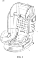
- a seat misuse alarm device 100 of the present invention includes a base 1, a seat 2, an alarm mechanism 3, and a switch triggering device 4.
- the seat 2 has a forward facing position and a rearward facing position relative to the base 1.
- the seat 2 is rotatably connected to the base 1.
- the seat 2 can be adjusted to the forward facing position or the rearward facing position via rotation of the seat 2 relative to the base 1, but the present invention is not limited thereto.
- the seat 2 could be detachably connected to the base 1. In such a manner, the seat 2 could be detached from the base 1, moved to the forward facing position or the rearward facing position, and then reassembled with the base 1.
- the alarm mechanism 3 is disposed on one of the base 1 and the seat 2, and the switch triggering device 4 is disposed on the other of the base 1 and the seat 2.
- the alarm mechanism 3 has a switch 31.
- the switch triggering device 4 triggers the switch 31 to close, so as to make the alarm mechanism 3 send out an alarm.
- the alarm mechanism 3 is disposed on the base 1, and the switch triggering device 4 is disposed on the seat 2.
- the switch triggering device 4 With rotation of the seat 2 to the forward facing position relative to the base 1, the switch triggering device 4 rotates to be aligned with the switch 31 of the alarm mechanism 3 and then trigger the switch 31 to close for making the alarm mechanism 3 send out the alarm, so as to remind a user not to put a child from 0 to 15 months on the seat 2 located at the forward facing position.
- the alarm mechanism 3 could be disposed on the seat 2 and the switch triggering device 4 could be disposed on the base 1 for achieving the same alarm effect.
- a first hole 11 is formed at a side of the base 1, and the switch 31 is disposed in the first hole 11.
- a second hole 21 is formed at a side of the seat 2, and the switch triggering device 4 is disposed through the second hole 21. With rotation of the seat 2 to the forward facing position relative to the base 1, the first hole 11 is aligned with the second hole 21 to make an end of the switch triggering device 4 extend into the first hole 11 and then trigger the switch 31 to close.
- the switch triggering device 4 includes a driving member 41 and an elastic returning member 42.
- the driving member 41 is slidably disposed in the second hole 21.
- the elastic returning member 42 is disposed between the driving member 41 and the seat 2 for providing an elastic force to make the driving member 41 ejected out of the second hole 21.
- the elastic returning member 42 could be a conventional compression spring commonly seen in the prior art.
- the switch triggering device 4 is not limited to the aforesaid embodiment, meaning that the present invention could adopt the design that the switch triggering device is an elastic deformable member in another embodiment.
- a first limiting portion 211 is formed on an inner wall of the second hole 21, and a protrusion 411 is formed on the driving member 41.
- the protrusion 411 is formed on a middle portion of the driving member 41, and the elastic returning member 42 is disposed between the first limiting portion 211 and the protrusion 411.
- a fixing base 212 is fixed to the inner wall of the second hole 21, and the first limiting portion 211 protrudes from the fixing base 212, and the elastic returning member 42 jackets the driving member 41.
- the design of the first limiting portion 211 is not limited to the aforesaid embodiment.
- the present invention could adopt the design that the first limiting portion 211 directly protrudes from the inner wall of the second hole 21.
- a second limiting portion 213 protrudes from the fixing base 212 and is spaced apart from the first limiting portion 211, and the protrusion 411 is located between the first limiting portion 211 and the second limiting portion 213.
- the driving member 41 can be partially constrained in the second hole 21 by the second limiting portion 213 limiting the protrusion 411 of the driving member 41, so as to prevent complete ejection of the driving member 41 out of the second hole 21 via the elastic force provided by the elastic returning member 42.
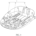
- the alarm mechanism 3 includes a control device 32 and an alarm device 33.
- the switch 31, the control device 32, and the alarm device 33 are electrically connected to each other and cooperatively form an alarm circuit.
- the control device 32 controls the alarm device 33 to send out the alarm.
- the control device 32 is disposed in the base 1 and located at a middle portion of the base 1
- the alarm device 33 is located at an outer front end of the base 1
- the switch 31 is electrically connected to the control device 32 and the alarm device 33 via wires.
- a power source is disposed in the control device 32.
- the related description for the control device 32 and the alarm device 33 is omitted since it is commonly seen in the prior art.
- the control device 32 controls the alarm device 33 to stop sending out the alarm.
- the predetermined value could be set as two, three, or four seconds, but not limited thereto.
- the control device 32 controls the alarm device 33 to send out the alarm.
- the control device 32 controls the alarm device 33 to stop sending out the alarm until next time that the driving member 41 triggers the switch 31 again.
- the detailed description for the operations of the seat misuse alarm device 100 is provided as follows according to FIGS. 1-8 .
- the first hole 11 is misaligned with the second hole 21, and the side wall of the base 1 presses the driving member 41 into the second hole 21 to make the elastic returning member 42 compressed by the driving member 41.
- the switch 31 is in an open state, and the alarm device 33 does not send out the alarm.
- the control device 32 controls the alarm device 33 to send out the alarm for reminding the user not to put a child from 0 to 15 months on the seat 2 located at the forward facing position. After the alarm time of the alarm device 33 reaches to the predetermined value, the control device 32 controls the alarm device to stop sending out the alarm until next time that the driving member 41 triggers the switch 31 again.
- the present invention adopts the design that the alarm device 3 is disposed on one of the base 1 and the seat 2 and the switch triggering device 4 is disposed on the other of the base 1 and the seat 2.
- the switch triggering device 4 With rotation of the seat 2 to the forward facing position relative to the base 1, the switch triggering device 4 rotates to be aligned with the switch 31 of the alarm mechanism 3, and then triggers the switch 31 to close for making the alarm mechanism 3 send out the alarm, so as to remind the user not to put a child from 0 to 15 months on the seat 2 located at the forward facing position.
- the present invention improves operational safety in use of a child safety seat.
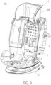
- FIG. 9 is a diagram of a headrest 101 of the seat misuse alarm device 100 sliding upward to a higher position.
- FIG. 10 is a diagram of the headrest 101 of the seat misuse alarm device 100 sliding downward to a lower position.
- FIG. 11 is a back view of the seat misuse alarm device 100 in FIG. 9 .
- the seat misuse alarm device 100 could further include a headrest mechanism 5.
- the headrest mechanism 5 is movably disposed on the seat 2 and electrically connected to the alarm mechanism 3.
- the headrest mechanism 5 could include the headrest 101, a headrest fixing base 102, and a headrest triggering switch 103, but the present invention is not limited thereto.
- the headrest 101 is slidably disposed on a front side F of the seat 2 to be slidable between the higher position as shown in FIG. 9 and the lower position as shown in FIG. 10 relative to the seat 2, but the present invention is not limited thereto.
- the headrest 101 passes through the seat 2 to be connected to the headrest fixing base 102 located at a back side B of the seat 2, so that the headrest fixing base 102 can slide together with the headrest 101 relative to the seat 2.
- the headrest triggering switch 103 is disposed on the back side B of the seat 2 and is electrically connected to the alarm mechanism 3.
- FIG. 12 which is a circuit diagram of the headrest triggering switch 103 in FIG. 11 , the switch 31, the control device 32, and the alarm device 33
- the headrest triggering switch 103 can form an alarm circuit 104 cooperatively with the switch 31, the control device 32, and the alarm device 33.
- FIG. 13 which is a diagram of the headrest fixing base 102 in FIG.
- the headrest fixing base 102 has a driving rib 105 protruding therefrom corresponding to the headrest triggering switch 103 for pressing the headrest triggering switch 103 to close, but the present invention is not limited thereto.
- the elastic returning member 42 drives the driving member 41 to be ejected out of the second hole 21 and then extend into the first hole 11 of the base 1 for triggering the switch 31 to close.
- the headrest fixing base 102 can slide synchronously to a position where the driving rib 105 presses the headrest triggering switch 103 to close (as shown in FIG.
- the alarm circuit 104 can be in a closed state such that the control device 32 can control the alarm device 33 to send out the alarm (e.g. light or sound). Accordingly, the seat misuse alarm device 100 can more precisely remind a user not to put a child from 0 to 15 months on the seat 2 located at the forward facing position.
- the alarm circuit 104 is in an open state since the headrest fixing base 102 is away from the headrest triggering switch 103 and fails to trigger the headrest triggering switch 103 to close. Therefore, the alarm device 33 does not send out the alarm.
- the present invention could adopt the circuit breaking design.
- the headrest mechanism 5 could only include the headrest 101.
- the headrest 101 is electrically connected to the alarm mechanism 3 for cooperatively forming an alarm circuit, and the headrest 101 can break the alarm circuit (the related description for the circuit breaking design is commonly seen in the prior art and omitted herein) accordingly when the headrest 101 slides to the higher position (corresponding to a headrest position of a child above 15 months, which means the user has no intention to put a child from 0 to 15 months on the seat 2 at the forward facing position).
- the alarm mechanism 3 does not send out the alarm, so as to prevent the user from unnecessary trouble in operating the seat 2.
- the present application further includes the following aspects:
Landscapes
- Engineering & Computer Science (AREA)
- Mechanical Engineering (AREA)
- Aviation & Aerospace Engineering (AREA)
- Transportation (AREA)
- General Health & Medical Sciences (AREA)
- Child & Adolescent Psychology (AREA)
- Health & Medical Sciences (AREA)
- Business, Economics & Management (AREA)
- Emergency Management (AREA)
- Physics & Mathematics (AREA)
- General Physics & Mathematics (AREA)
- Seats For Vehicles (AREA)
- Emergency Alarm Devices (AREA)
- Burglar Alarm Systems (AREA)
Abstract
Description
- The present invention relates to a seat misuse alarm device according to the precharacterizing clause of
claim 1. - A child safety seat is designed for ensuring safety of a child in a car. In general, the child safety seat is assembled in the car to allow the child sitting thereon for constraining the child in the car, so as to ensure safety of the child. A conventional child safety seat usually includes a base and a seat rotatably disposed on the base. The seat has a forward facing position and a rearward facing position relative to the base, so that a user can adjust the seat to a desired position according to the practical needs. For safety issues, it is forbidden that the user adjusts the seat to the forward facing position and then put a child from 0 to 15 months on the seat. However, since the child safety seat does not have a seat misuse alarm function, the user often puts a child from 0 to 15 months on the seat at the forward facing position by mistake. Thus, it may cause a great risk to safety of a child in a car.
- Therefore, it is necessary to design a seat misuse alarm device for solving the aforesaid problem.
- The present invention aims at providing a seat misuse alarm device for sending out an alarm when a seat is misused.
- This is achieved by a seat misuse alarm device according to
claim 1. The dependent claims pertain to corresponding further developments and improvements. - As will be seen more clearly from the detailed description following below, the claimed seat misuse alarm device of the present invention includes a base, a seat, an alarm mechanism, and a switch triggering device. The seat has a forward facing position and a rearward facing position relative the base. The alarm mechanism has a switch. The switch triggering device triggers the switch to close for making the alarm mechanism send out an alarm when the seat is located at the forward facing position relative to the base.
- Preferably, the seat is rotatably connected to the base.
- Preferably, the alarm mechanism is disposed on one of the base and the seat, and the switch triggering device is disposed on the other of the base and the seat.
- Preferably, the alarm mechanism is disposed on the base, and the switch triggering device is disposed on the seat.
- Preferably, a first hole is formed at a side of the base, the switch is located in the first hole, a second hole is formed at a side of the seat, the switch triggering device is disposed through the second hole, and with rotation of the seat to the forward facing position relative to the base, the first hole is aligned with the second hole to make an end of the switch triggering device extend into the first hole and then trigger the switch to close.
- Preferably, the switch triggering device includes a driving member and an elastic returning member, the driving member is slidably disposed in the second hole, and the elastic returning member is disposed between the driving member and the seat for providing an elastic force to make the driving member ejected from the second hole.
- Preferably, a first limiting portion is formed on an inner wall of the second hole, a protrusion is formed on the driving member, and the elastic returning member is disposed between the first limiting portion and the protrusion.
- Preferably, a fixing base is fixed to the inner wall of the second hole, and the first limiting portion protrudes from the fixing base.
- Preferably, a second limiting portion is formed on the fixing base and is spaced apart from the first limiting portion, and the protrusion is located between the first limiting portion and the second limiting portion.
- Preferably, the elastic returning member jackets the driving member.
- Preferably, the alarm mechanism includes a control device and an alarm device, the switch, the control device, and the alarm device are electrically connected to each other and cooperatively form an alarm circuit, and when the switch is triggered to close, the control device controls the alarm device to send out the alarm.
- Preferably, after an alarm time of the alarm device reaches to a predetermined value, the control device controls the alarm device to stop sending out the alarm.
- Preferably, the seat misuse alarm device further includes a headrest mechanism. The headrest mechanism is movably disposed on the seat and electrically connected to the alarm mechanism. When the seat is located at the forward facing position relative to the base for triggering the switch to close, a height of the headrest mechanism relative to the seat determines whether to conduct the alarm mechanism for making the alarm mechanism selectively send out the alarm.
- Preferably, the headrest mechanism includes a headrest, a headrest fixing base, and a headrest triggering switch, the headrest is slidably disposed on a front side of the seat to be slidable between a higher position and a lower position relative to the seat, the headrest passes through the seat to be connected to the headrest fixing base located on a back side of the seat for making the headrest fixing base slidable together with the headrest, the headrest triggering switch is disposed on the back side of the seat and is electrically connected to the alarm mechanism, and the alarm mechanism sends out the alarm when the headrest slides to the lower position relative to the seat to make the headrest fixing base trigger the headrest triggering switch to close and the seat is located at the forward facing position relative to the base to trigger the switch to close.
- Preferably, the headrest fixing base has a driving rib protruding therefrom corresponding to the headrest triggering switch, and the driving rib presses the headrest triggering switch to close when the headrest slides to the lower position relative to the seat.
- Preferably, when the headrest slides away from the lower position relative to the seat to make the headrest fixing base not trigger the headrest triggering switch to close, the alarm device does not send out the alarm.
- Preferably, the headrest mechanism includes a headrest, the headrest is slidably disposed on a front side of the seat to be slidable between a higher position and a lower position, the headrest is electrically connected to the alarm mechanism for cooperatively forming an alarm circuit, and the headrest breaks the alarm circuit to make the alarm device not send out the alarm when the headrest slides to the higher position relative to the seat.
- Compared with the prior art, the present invention adopts the design that the switch triggering device is aligned with the switch of the alarm mechanism for triggering the switch to close when the seat is located at the forward facing position relative to the base. In such a manner, the alarm mechanism can send out an alarm to remind a user not to put a child from 0 to 15 months on the seat at the forward facing position. Thus, the present invention can improve operational safety in use of a child safety seat.
- In the following, the invention is further illustrated by way of example, taking reference to the accompanying drawings thereof:
-
FIG. 1 is a diagram of a seat misuse alarm device of the present invention, -
FIG. 2 is an enlarged diagram of a base of the seat misuse alarm device of the present invention, -
FIG. 3 is an enlarged diagram of "A" region inFIG. 2 , -
FIG. 4 is an internal diagram of the base of the seat misuse alarm device after an upper cover is omitted, -
FIG. 5 is a diagram of a seat of the seat misuse alarm device of the present invention, -
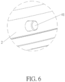
FIG. 6 is an enlarged diagram of "B" region inFIG. 5 , -
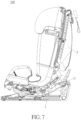
FIG. 7 is a cross-sectional diagram of the seat misuse alarm device of the present invention, -
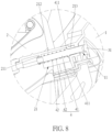
FIG. 8 is an enlarged diagram of "C" region inFIG. 7 , -
FIG. 9 is a diagram of a headrest of the seat misuse alarm device sliding upward to a higher position, -
FIG. 10 is a diagram of the headrest of the seat misuse alarm device sliding downward to a lower position, -
FIG. 11 is a back view of the seat misuse alarm device inFIG. 9 , -
FIG. 12 is a circuit diagram of a headrest triggering switch inFIG. 11 , a switch, a control device, and an alarm device, and -
FIG. 13 is a diagram of a headrest fixing base inFIG. 11 sliding downward to the lower position. - The embodiments of the present invention will now be described with reference to the accompanying drawings.
- Please refer to
FIG. 1 ,FIG. 7 , andFIG. 8 . A seatmisuse alarm device 100 of the present invention includes abase 1, aseat 2, analarm mechanism 3, and a switch triggering device 4. Theseat 2 has a forward facing position and a rearward facing position relative to thebase 1. Specifically, theseat 2 is rotatably connected to thebase 1. As such, theseat 2 can be adjusted to the forward facing position or the rearward facing position via rotation of theseat 2 relative to thebase 1, but the present invention is not limited thereto. For example, theseat 2 could be detachably connected to thebase 1. In such a manner, theseat 2 could be detached from thebase 1, moved to the forward facing position or the rearward facing position, and then reassembled with thebase 1. Thealarm mechanism 3 is disposed on one of thebase 1 and theseat 2, and the switch triggering device 4 is disposed on the other of thebase 1 and theseat 2. Thealarm mechanism 3 has aswitch 31. When theseat 2 rotates to the forward facing position relative to thebase 1, the switch triggering device 4 triggers theswitch 31 to close, so as to make thealarm mechanism 3 send out an alarm. In this embodiment, thealarm mechanism 3 is disposed on thebase 1, and the switch triggering device 4 is disposed on theseat 2. With rotation of theseat 2 to the forward facing position relative to thebase 1, the switch triggering device 4 rotates to be aligned with theswitch 31 of thealarm mechanism 3 and then trigger theswitch 31 to close for making thealarm mechanism 3 send out the alarm, so as to remind a user not to put a child from 0 to 15 months on theseat 2 located at the forward facing position. In another embodiment, thealarm mechanism 3 could be disposed on theseat 2 and the switch triggering device 4 could be disposed on thebase 1 for achieving the same alarm effect. - Please refer to
FIG. 2, FIG. 3 , andFIG. 8 . Afirst hole 11 is formed at a side of thebase 1, and theswitch 31 is disposed in thefirst hole 11. Asecond hole 21 is formed at a side of theseat 2, and the switch triggering device 4 is disposed through thesecond hole 21. With rotation of theseat 2 to the forward facing position relative to thebase 1, thefirst hole 11 is aligned with thesecond hole 21 to make an end of the switch triggering device 4 extend into thefirst hole 11 and then trigger theswitch 31 to close. - Please refer to
FIG. 5-8 . In this embodiment, the switch triggering device 4 includes a drivingmember 41 and an elastic returningmember 42. The drivingmember 41 is slidably disposed in thesecond hole 21. The elastic returningmember 42 is disposed between the drivingmember 41 and theseat 2 for providing an elastic force to make the drivingmember 41 ejected out of thesecond hole 21. The elastic returningmember 42 could be a conventional compression spring commonly seen in the prior art. When theseat 2 is located at the rearward facing position relative to thebase 1, a side wall of thebase 1 presses the drivingmember 41 into thesecond hole 21, so as to make the elastic returningmember 42 compressed by the drivingmember 41. When theseat 2 rotates to the forward facing position relative to thebase 1, thefirst hole 11 is aligned with thesecond hole 21, and the elastic force of the elastic returningmember 42 drives an end of the drivingmember 41 to be ejected out of thesecond hole 21 and then extend into thefirst hole 11 of thebase 1 since the drivingmember 41 is no longer pressed by the side wall of thebase 1, so that the drivingmember 41 can trigger theswitch 31 to close for making thealarm mechanism 3 send out the alarm. To be noted, the design of the switch triggering device 4 is not limited to the aforesaid embodiment, meaning that the present invention could adopt the design that the switch triggering device is an elastic deformable member in another embodiment. Specifically, a first limitingportion 211 is formed on an inner wall of thesecond hole 21, and aprotrusion 411 is formed on the drivingmember 41. Theprotrusion 411 is formed on a middle portion of the drivingmember 41, and the elastic returningmember 42 is disposed between the first limitingportion 211 and theprotrusion 411. To be more specific, a fixingbase 212 is fixed to the inner wall of thesecond hole 21, and the first limitingportion 211 protrudes from the fixingbase 212, and the elastic returningmember 42 jackets the drivingmember 41. The design of the first limitingportion 211 is not limited to the aforesaid embodiment. For example, the present invention could adopt the design that the first limitingportion 211 directly protrudes from the inner wall of thesecond hole 21. Furthermore, a second limitingportion 213 protrudes from the fixingbase 212 and is spaced apart from the first limitingportion 211, and theprotrusion 411 is located between the first limitingportion 211 and the second limitingportion 213. As such, the drivingmember 41 can be partially constrained in thesecond hole 21 by the second limitingportion 213 limiting theprotrusion 411 of the drivingmember 41, so as to prevent complete ejection of the drivingmember 41 out of thesecond hole 21 via the elastic force provided by the elastic returningmember 42. - Please refer to
FIG. 2 andFIG. 4 . In this embodiment, thealarm mechanism 3 includes acontrol device 32 and analarm device 33. Theswitch 31, thecontrol device 32, and thealarm device 33 are electrically connected to each other and cooperatively form an alarm circuit. When theswitch 31 is triggered to close, thecontrol device 32 controls thealarm device 33 to send out the alarm. Specifically, thecontrol device 32 is disposed in thebase 1 and located at a middle portion of thebase 1, thealarm device 33 is located at an outer front end of thebase 1, and theswitch 31 is electrically connected to thecontrol device 32 and thealarm device 33 via wires. A power source is disposed in thecontrol device 32. The related description for thecontrol device 32 and thealarm device 33 is omitted since it is commonly seen in the prior art. Furthermore, after an alarm time of thealarm device 33 reaches to a predetermined value, thecontrol device 32 controls thealarm device 33 to stop sending out the alarm. For example, the predetermined value could be set as two, three, or four seconds, but not limited thereto. In such a manner, when theseat 2 rotates to the forward facing position relative to thebase 1 and the drivingmember 41 triggers theswitch 31 to close for conducting the alarm circuit, thecontrol device 32 controls thealarm device 33 to send out the alarm. After the alarm time of thealarm device 33 reaches to the predetermined value, thecontrol device 32 controls thealarm device 33 to stop sending out the alarm until next time that the drivingmember 41 triggers theswitch 31 again. - The detailed description for the operations of the seat
misuse alarm device 100 is provided as follows according toFIGS. 1-8 . - When the
seat 2 is located at the rearward facing position relative to thebase 1, thefirst hole 11 is misaligned with thesecond hole 21, and the side wall of thebase 1 presses the drivingmember 41 into thesecond hole 21 to make the elastic returningmember 42 compressed by the drivingmember 41. At this time, theswitch 31 is in an open state, and thealarm device 33 does not send out the alarm. When theseat 2 rotates to the forward facing position relative to thebase 1, thefirst hole 11 is aligned with thesecond hole 21, and the elastic force of the elastic returningmember 42 drives the end of the drivingmember 41 to be ejected out of thesecond hole 21 and then extend into thefirst hole 11 of thebase 1 since the drivingmember 41 is no longer pressed by the side wall of thebase 1, so that the drivingmember 41 can trigger theswitch 31 to close for conducting the alarm circuit. At this time, thecontrol device 32 controls thealarm device 33 to send out the alarm for reminding the user not to put a child from 0 to 15 months on theseat 2 located at the forward facing position. After the alarm time of thealarm device 33 reaches to the predetermined value, thecontrol device 32 controls the alarm device to stop sending out the alarm until next time that the drivingmember 41 triggers theswitch 31 again. - In summary, the present invention adopts the design that the
alarm device 3 is disposed on one of thebase 1 and theseat 2 and the switch triggering device 4 is disposed on the other of thebase 1 and theseat 2. With rotation of theseat 2 to the forward facing position relative to thebase 1, the switch triggering device 4 rotates to be aligned with theswitch 31 of thealarm mechanism 3, and then triggers theswitch 31 to close for making thealarm mechanism 3 send out the alarm, so as to remind the user not to put a child from 0 to 15 months on theseat 2 located at the forward facing position. In such a manner, the present invention improves operational safety in use of a child safety seat. - Furthermore, please refer to
FIG. 9 ,FIG. 10 , andFIG. 11 .FIG. 9 is a diagram of aheadrest 101 of the seatmisuse alarm device 100 sliding upward to a higher position.FIG. 10 is a diagram of theheadrest 101 of the seatmisuse alarm device 100 sliding downward to a lower position.FIG. 11 is a back view of the seatmisuse alarm device 100 inFIG. 9 . As shown inFIG. 9 ,FIG. 10 , andFIG. 11 , the seatmisuse alarm device 100 could further include aheadrest mechanism 5. Theheadrest mechanism 5 is movably disposed on theseat 2 and electrically connected to thealarm mechanism 3. Accordingly, when theseat 2 is located at the forward facing position relative to thebase 1 for triggering theswitch 31 to close, a height of theheadrest mechanism 5 relative to theseat 2 can determine whether to conduct thealarm mechanism 3 for making thealarm mechanism 3 selectively send out the alarm or not. For example, theheadrest mechanism 5 could include theheadrest 101, aheadrest fixing base 102, and aheadrest triggering switch 103, but the present invention is not limited thereto. Theheadrest 101 is slidably disposed on a front side F of theseat 2 to be slidable between the higher position as shown inFIG. 9 and the lower position as shown inFIG. 10 relative to theseat 2, but the present invention is not limited thereto. Theheadrest 101 passes through theseat 2 to be connected to theheadrest fixing base 102 located at a back side B of theseat 2, so that theheadrest fixing base 102 can slide together with theheadrest 101 relative to theseat 2. Theheadrest triggering switch 103 is disposed on the back side B of theseat 2 and is electrically connected to thealarm mechanism 3. To be more specific, as shown inFIG. 12 , which is a circuit diagram of theheadrest triggering switch 103 inFIG. 11 , theswitch 31, thecontrol device 32, and thealarm device 33, theheadrest triggering switch 103 can form analarm circuit 104 cooperatively with theswitch 31, thecontrol device 32, and thealarm device 33. In addition, please refer toFIG. 13 , which is a diagram of theheadrest fixing base 102 inFIG. 11 sliding downward to the lower position. In practical application, as shown inFIG. 13 , theheadrest fixing base 102 has a drivingrib 105 protruding therefrom corresponding to theheadrest triggering switch 103 for pressing theheadrest triggering switch 103 to close, but the present invention is not limited thereto. - As mentioned above, when the
seat 2 rotates to the forward facing position relative to thebase 1, the elastic returningmember 42 drives the drivingmember 41 to be ejected out of thesecond hole 21 and then extend into thefirst hole 11 of thebase 1 for triggering theswitch 31 to close. At this time, via the aforesaid circuit design, if the user further slides theheadrest 101 downward to the lower position (corresponding to a headrest position of a child from 0 to 15 months, which means the user has an intention to put the child from 0 to 15 months on theseat 2 at the forward facing position) as shown inFIG. 10 relative to theseat 2, theheadrest fixing base 102 can slide synchronously to a position where the drivingrib 105 presses theheadrest triggering switch 103 to close (as shown inFIG. 13 ). In such a manner, via the two-stage conduction design that the drivingmember 41 presses theswitch 31 to close and theheadrest fixing base 102 presses theheadrest triggering switch 103 to close, thealarm circuit 104 can be in a closed state such that thecontrol device 32 can control thealarm device 33 to send out the alarm (e.g. light or sound). Accordingly, the seatmisuse alarm device 100 can more precisely remind a user not to put a child from 0 to 15 months on theseat 2 located at the forward facing position. - On the other hand, if the
seat 2 rotates to the forward facing position relative to thebase 1 and theheadrest 101 slides away from the lower position (e.g. sliding upward to the higher position (corresponding to a headrest position of a child above 15 months) as shown inFIG. 11 , which means the user has no intention to put a child from 0 to 15 months on theseat 2 at the forward facing position), thealarm circuit 104 is in an open state since theheadrest fixing base 102 is away from theheadrest triggering switch 103 and fails to trigger theheadrest triggering switch 103 to close. Therefore, thealarm device 33 does not send out the alarm. - Moreover, the present invention could adopt the circuit breaking design. To be brief, in this design, the
headrest mechanism 5 could only include theheadrest 101. Theheadrest 101 is electrically connected to thealarm mechanism 3 for cooperatively forming an alarm circuit, and theheadrest 101 can break the alarm circuit (the related description for the circuit breaking design is commonly seen in the prior art and omitted herein) accordingly when theheadrest 101 slides to the higher position (corresponding to a headrest position of a child above 15 months, which means the user has no intention to put a child from 0 to 15 months on theseat 2 at the forward facing position). In such a manner, no matter theseat 2 is located at the forward facing position or the rearward facing position, thealarm mechanism 3 does not send out the alarm, so as to prevent the user from unnecessary trouble in operating theseat 2. - Those skilled in the art will readily observe that numerous modifications and alterations of the device and method may be made while retaining the teachings of the invention. Accordingly, the above disclosure should be construed as limited only by the metes and bounds of the appended claims.
- The present application further includes the following aspects:
- 1. A seat misuse alarm device (100) comprising:
- a base (1);
- a seat (2) having a forward facing position and a rearward facing position relative the base (1); characterized by:
- an alarm mechanism (3) having a switch (31); and
- a switch triggering device (4) triggering the switch (31) to close for making the alarm mechanism (3) send out an alarm when the seat (2) is located at the forward facing position relative to the base (1).
- 2. The seat misuse alarm device (100) of
aspect 1, characterized in that the seat (2) is rotatably connected to the base (1). - 3. The seat misuse alarm device (100) of
aspect 1, characterized in that the alarm mechanism (3) is disposed on one of the base (1) and the seat (2), and the switch triggering device (4) is disposed on the other of the base (1) and the seat (2). - 4. The seat misuse alarm device (100) of
aspect 3, characterized in that the alarm mechanism (3) is disposed on the base (1), and the switch triggering device (4) is disposed on the seat (2). - 5. The seat misuse alarm device (100) of aspect 4, characterized in that a first hole (11) is formed at a side of the base (1), the switch (31) is located in the first hole (11), a second hole (21) is formed at a side of the seat (2), the switch triggering device (4) is disposed through the second hole (21), and with rotation of the seat (2) to the forward facing position relative to the base (1), the first hole (11) is aligned with the second hole (21) to make an end of the switch triggering device (4) extend into the first hole (11) and then trigger the switch (31) to close.
- 6. The seat misuse alarm device (100) of
aspect 5, characterized in that the switch triggering device (4) comprises a driving member (41) and an elastic returning member (42), the driving member (41) is slidably disposed in the second hole (21), and the elastic returning member (42) is disposed between the driving member (41) and the seat (2) for providing an elastic force to make the driving member (41) ejected from the second hole (21). - 7. The seat misuse alarm device (100) of aspect 6, characterized in that a first limiting portion (211) is formed on an inner wall of the second hole (21), a protrusion (411) is formed on the driving member (41), and the elastic returning member (42) is disposed between the first limiting portion (211) and the protrusion (411).
- 8. The seat misuse alarm device (100) of aspect 7, characterized in that a fixing base (212) is fixed to the inner wall of the second hole (21), and the first limiting portion (211) protrudes from the fixing base (212).
- 9. The seat misuse alarm device (100) of aspect 8, characterized in that a second limiting portion (213) is formed on the fixing base (212) and is spaced apart from the first limiting portion (211), and the protrusion (411) is located between the first limiting portion (211) and the second limiting portion (213).
- 10. The seat misuse alarm device (100) of aspect 6, characterized in that the elastic returning member (42) jackets the driving member (41).
- 11. The seat misuse alarm device (100) of
aspect 1, characterized in that the alarm mechanism (3) includes a control device (32) and an alarm device (33), the switch (31), the control device (32), and the alarm device (33) are electrically connected to each other and cooperatively form an alarm circuit, and when the switch (31) is triggered to close, the control device (32) controls the alarm device (33) to send out the alarm. - 12. The seat misuse alarm device (100) of
aspect 11, characterized in that after an alarm time of the alarm device (33) reaches to a predetermined value, the control device (32) controls the alarm device (33) to stop sending out the alarm. - 13. The seat misuse alarm device (100) of
aspect 1, characterized in that the seat misuse alarm device (100) further comprises a headrest mechanism (5), the headrest mechanism (5) is movably disposed on the seat (2) and electrically connected to the alarm mechanism (3), and when the seat (2) is located at the forward facing position relative to the base (1) for triggering the switch (31) to close, a height of the headrest mechanism (5) relative to the seat (2) determines whether to conduct the alarm mechanism (3) for making the alarm mechanism (3) selectively send out the alarm. - 14. The seat misuse alarm device (100) of aspect 13, characterized in that the headrest mechanism comprises a headrest (101), a headrest fixing base (102), and a headrest triggering switch (103), the headrest (101) is slidably disposed on a front side of the seat (2) to be slidable between a higher position and a lower position relative to the seat (2), the headrest (101) passes through the seat (2) to be connected to the headrest fixing base (102) located on a back side of the seat (2) for making the headrest fixing base (102) slidable together with the headrest (101), the headrest triggering switch (103) is disposed on the back side of the seat (2) and is electrically connected to the alarm mechanism (3), and the alarm mechanism (5) sends out the alarm when the headrest (101) slides to the lower position relative to the seat (2) to make the headrest fixing base (102) trigger the headrest triggering switch (103) to close and the seat (2) is located at the forward facing position relative to the base (1) to trigger the switch (31) to close.
- 15. The seat misuse alarm device (100) of aspect 14, characterized in that the headrest fixing base (102) has a driving rib (105) protruding therefrom corresponding to the headrest triggering switch (103), and the driving rib (105) presses the headrest triggering switch (103) to close when the headrest (101) slides to the lower position relative to the seat (2).
- 16. The seat misuse alarm device (100) of aspect 14, characterized in that when the headrest (101) slides away from the lower position relative to the seat (2) to make the headrest fixing base (102) not trigger the headrest triggering switch (103) to close, the alarm device (33) does not send out the alarm.
- 17. The seat misuse alarm device (100) of aspect 13, characterized in that the headrest mechanism (5) comprises a headrest (101), the headrest (101) is slidably disposed on a front side of the seat (2) to be slidable between a higher position and a lower position, the headrest (101) is electrically connected to the alarm mechanism (3) for cooperatively forming an alarm circuit, and the headrest (101) breaks the alarm circuit to make the alarm device (33) not send out the alarm when the headrest (101) slides to the higher position relative to the seat (2).
Claims (15)
- A seat misuse alarm device (100) comprising:a base (1);a seat (2) rotatably connected to the base (1), having a forward facing position and a rearward facing position relative the base (1); characterized by:an alarm mechanism (3) having a switch (31); anda switch triggering device (4) triggering the switch (31) to close for making the alarm mechanism (3) send out an alarm when the seat (2) is located at the forward facing position relative to the base (1),characterized in that the alarm mechanism (3) is disposed on one of the base (1) and the seat (2), and the switch triggering device (4) is disposed on the other of the base (1) and the seat (2).
- The seat misuse alarm device (100) of claim 1, characterized in that with rotation of the seat (2) to the forward facing position relative to the base (1,) the switch triggering device (4) rotates to be aligned with the switch (31) of the alarm mechanism (3) and then trigger the switch (31) to close for making the alarm mechanism (3) send out the alarm, so as to remind a user not to put a child from 0 to 15 months on the seat (2) located at the forward facing position.
- The seat misuse alarm device (100) of claim 1, characterized in that a first hole is formed at a side of the base (1) and the seat (2), a second hole (21) is formed at a side of the other of the base (1) and the seat (2).
- The seat misuse alarm device (100) of one of claims 1, 2 or 3, wherein the switch triggering device (4) comprises a driving member (41), and the driving member (41) is slidably disposed in the second hole (21).
- The seat misuse alarm device (100) of claim 4, wherein when the seat (2) is located at the rearward facing position relative to the base (1), a first hole (11) is misaligned with a second hole (21); and/or
when the seat (2) is located at the rearward facing position relative to the base (1), a side wall of the base (1) presses the driving member (41) into the second hole (21). - The seat misuse alarm device (100) of claim 4, wherein the switch (31) is located in the first hole (11), with rotation of the seat (2) to the forward facing position relative to the base (1), the first hole (11) is aligned with the second hole (21) to make an end of the switch triggering device (4) extend into the first hole (11) and then trigger the switch (31) to close.
- The seat misuse alarm device (100) of claim 4, 5 or 6, characterized in that the switch triggering device (4) comprises an elastic returning member (42), the elastic returning member (42) is disposed between the driving member (41) and the seat (2) for providing an elastic force to make the driving member (41) ejected from the second hole (21).
- The seat misuse alarm device (100) of claim 7, characterized in that a first limiting portion (211) is formed on an inner wall of the second hole (21), a protrusion (411) is formed on the driving member (41), and the elastic returning member (42) is disposed between the first limiting portion (211) and the protrusion (411).
- The seat misuse alarm device (100) of claim 8, characterized in that a fixing base (212) is fixed to the inner wall of the second hole (21), and the first limiting portion (211) protrudes from the fixing base (212).
- The seat misuse alarm device (100) of claim 9, characterized in that a second limiting portion (213) is formed on the fixing base (212) and is spaced apart from the first limiting portion (211), and the protrusion (411) is located between the first limiting portion (211) and the second limiting portion (213).
- The seat misuse alarm device (100) of claim 1, characterized in that the alarm mechanism (3) includes a control device (32) and an alarm device (33), the switch (31), the control device (32), and the alarm device (33) are electrically connected to each other and cooperatively form an alarm circuit, and when the switch (31) is triggered to close, the control device (32) controls the alarm device (33) to send out the alarm.
- The seat misuse alarm device (100) of claim 1, characterized in that the seat misuse alarm device (100) further comprises a headrest mechanism (5), the headrest mechanism (5) is movably disposed on the seat (2) and electrically connected to the alarm mechanism (3), and when the seat (2) is located at the forward facing position relative to the base (1) for triggering the switch (31) to close, a height of the headrest mechanism (5) relative to the seat (2) determines whether to conduct the alarm mechanism (3) for making the alarm mechanism (3) selectively send out the alarm.
- The seat misuse alarm device (100) of claim 12, characterized in that the headrest mechanism comprises a headrest (101), a headrest fixing base (102), and a headrest triggering switch (103), the headrest (101) is slidably disposed on a front side of the seat (2) to be slidable between a higher position and a lower position relative to the seat (2), the headrest (101) passes through the seat (2) to be connected to the headrest fixing base (102) located on a back side of the seat (2) for making the headrest fixing base (102) slidable together with the headrest (101), the headrest triggering switch (103) is disposed on the back side of the seat (2) and is electrically connected to the alarm mechanism (3), and the alarm mechanism (5) sends out the alarm when the headrest (101) slides to the lower position relative to the seat (2) to make the headrest fixing base (102) trigger the headrest triggering switch (103) to close and the seat (2) is located at the forward facing position relative to the base (1) to trigger the switch (31) to close.
- The seat misuse alarm device (100) of claim 13, characterized in that the headrest fixing base (102) has a driving rib (105) protruding therefrom corresponding to the headrest triggering switch (103), and the driving rib (105) presses the headrest triggering switch (103) to close when the headrest (101) slides to the lower position relative to the seat (2),
and/or
characterized in that when the headrest (101) slides away from the lower position relative to the seat (2) to make the headrest fixing base (102) not trigger the headrest triggering switch (103) to close, the alarm device (33) does not send out the alarm. - The seat misuse alarm device (100) of claim 12, characterized in that the headrest mechanism (5) comprises a headrest (101), the headrest (101) is slidably disposed on a front side of the seat (2) to be slidable between a higher position and a lower position, the headrest (101) is electrically connected to the alarm mechanism (3) for cooperatively forming an alarm circuit, and the headrest (101) breaks the alarm circuit to make the alarm device (33) not send out the alarm when the headrest (101) slides to the higher position relative to the seat (2).
Applications Claiming Priority (3)
| Application Number | Priority Date | Filing Date | Title |
|---|---|---|---|
| CN202010141341.6A CN113352964A (en) | 2020-03-03 | 2020-03-03 | Forward misuse alarm device |
| PCT/EP2021/055262 WO2021175892A1 (en) | 2020-03-03 | 2021-03-03 | Seat misuse alarm device |
| EP21709950.6A EP4093636B1 (en) | 2020-03-03 | 2021-03-03 | Seat misuse alarm device |
Related Parent Applications (2)
| Application Number | Title | Priority Date | Filing Date |
|---|---|---|---|
| EP21709950.6A Division-Into EP4093636B1 (en) | 2020-03-03 | 2021-03-03 | Seat misuse alarm device |
| EP21709950.6A Division EP4093636B1 (en) | 2020-03-03 | 2021-03-03 | Seat misuse alarm device |
Publications (2)
| Publication Number | Publication Date |
|---|---|
| EP4458620A2 true EP4458620A2 (en) | 2024-11-06 |
| EP4458620A3 EP4458620A3 (en) | 2025-02-19 |
Family
ID=74858429
Family Applications (2)
| Application Number | Title | Priority Date | Filing Date |
|---|---|---|---|
| EP21709950.6A Active EP4093636B1 (en) | 2020-03-03 | 2021-03-03 | Seat misuse alarm device |
| EP24194651.6A Pending EP4458620A3 (en) | 2020-03-03 | 2021-03-03 | Seat misuse alarm device |
Family Applications Before (1)
| Application Number | Title | Priority Date | Filing Date |
|---|---|---|---|
| EP21709950.6A Active EP4093636B1 (en) | 2020-03-03 | 2021-03-03 | Seat misuse alarm device |
Country Status (9)
| Country | Link |
|---|---|
| US (3) | US11970125B2 (en) |
| EP (2) | EP4093636B1 (en) |
| JP (2) | JP7476333B2 (en) |
| CN (1) | CN113352964A (en) |
| AU (2) | AU2021231211B2 (en) |
| DE (1) | DE112021001387T5 (en) |
| ES (1) | ES3004520T3 (en) |
| TW (1) | TWI778534B (en) |
| WO (1) | WO2021175892A1 (en) |
Families Citing this family (3)
| Publication number | Priority date | Publication date | Assignee | Title |
|---|---|---|---|---|
| CN113352964A (en) | 2020-03-03 | 2021-09-07 | 宝钜瑞士股份有限公司 | Forward misuse alarm device |
| CN221023362U (en) * | 2022-05-20 | 2024-05-28 | 明门(中国)幼童用品有限公司 | Child safety seat and safety belt installation prompting system |
| CN115230544B (en) * | 2022-07-07 | 2024-02-20 | 欧颂科技(海南)有限公司 | Electric rotating lying angle adjusting structure of child safety seat |
Family Cites Families (33)
| Publication number | Priority date | Publication date | Assignee | Title |
|---|---|---|---|---|
| US4936629A (en) | 1988-10-07 | 1990-06-26 | Rock-A-Bye Restraint Company, Inc. | Swiveling infant car seat |
| US5260684A (en) * | 1991-05-14 | 1993-11-09 | Northpoint Manufacturing & Marketing, Inc. | Warning system for a child's restraining seat for use in a passenger vehicle |
| US5605348A (en) * | 1993-11-03 | 1997-02-25 | Trw Vehicle Safety Systems Inc. | Method and apparatus for sensing a rearward facing child seat |
| JP3288002B2 (en) | 1997-01-08 | 2002-06-04 | アップリカ▲葛▼西株式会社 | Automotive child safety seats |
| US6820895B2 (en) * | 1998-09-23 | 2004-11-23 | Vehicle Safety Systems, Inc. | Vehicle air bag minimum distance enforcement apparatus, method and system |
| DE19949933C1 (en) | 1999-10-16 | 2001-02-15 | Daimler Chrysler Ag | Child's seat for automobile e.g. limousine, has seat frame secured to floor pan of passenger space for forwards and backwards adjustment and relatively rotatable seat shell |
| EP1669251A1 (en) | 2004-12-07 | 2006-06-14 | IEE INTERNATIONAL ELECTRONICS & ENGINEERING S.A. | Child seat detection system |
| GB0504645D0 (en) * | 2005-03-07 | 2005-04-13 | Britax Roemer Kindersicherheit Gmbh | Child safety seat |
| WO2007113809A2 (en) * | 2006-03-30 | 2007-10-11 | Saban Asher S | Protecting children and passengers with respect to a vehicle |
| US7490898B2 (en) * | 2006-09-01 | 2009-02-17 | Cosco Management, Inc. | Child restraint with swiveling juvenile seat and swivel-status indicator |
| US7819472B2 (en) * | 2006-12-12 | 2010-10-26 | Wonderland Nurserygoods Co., Ltd. | Latch mechanism for a child car seat |
| US20120232749A1 (en) * | 2007-12-14 | 2012-09-13 | Schoenberg Gregory B | Systems and Methods for Indicating the Presence of a Child in a Vehicle |
| JP5247161B2 (en) | 2008-01-18 | 2013-07-24 | アップリカ・チルドレンズプロダクツ株式会社 | Child seat for automobile |
| JP5381322B2 (en) * | 2009-05-21 | 2014-01-08 | タカタ株式会社 | child seat |
| JP5603694B2 (en) | 2010-07-24 | 2014-10-08 | タカタ株式会社 | child seat |
| CN102092319B (en) * | 2011-01-13 | 2012-11-28 | 好孩子儿童用品有限公司 | Child vehicle safety seat with liquid crystal display |
| FR2978388B1 (en) * | 2011-07-28 | 2013-12-06 | Dorel France Sa | CHILD CAR SEAT, INTENDED TO BE SOLIDARIZED AT THE SEAT OF A MOTOR VEHICLE. |
| US9663032B1 (en) * | 2015-11-09 | 2017-05-30 | Ford Global Technologies, Llc | Child seat monitoring system and method |
| DE102016117312A1 (en) | 2016-09-14 | 2018-03-15 | Cybex Gmbh | Child seat |
| JP2018122618A (en) | 2017-01-30 | 2018-08-09 | 株式会社カーメイト | child seat |
| CN110431048B (en) | 2017-03-16 | 2022-05-24 | 本田技研工业株式会社 | Occupant protection device |
| CN110402211B (en) | 2017-03-16 | 2022-01-14 | 本田技研工业株式会社 | Passenger protection control device, passenger protection control method, and storage medium |
| CN110799380A (en) | 2017-04-25 | 2020-02-14 | 罗伯特·博世有限公司 | Electrically rotatable child seat, in particular for fastening to a motor vehicle seat |
| US10157534B2 (en) * | 2017-05-01 | 2018-12-18 | Tung Thanh PHAM | Multi-function retroreflective on-board alert system |
| JP7022270B2 (en) | 2017-06-20 | 2022-02-18 | テイ・エス テック株式会社 | Vehicle seat |
| CN110103786A (en) * | 2018-07-17 | 2019-08-09 | 宁波宝贝第一母婴用品有限公司 | A kind of child safety seat and its installation suggestion method with installation suggestion function |
| CN109177830B (en) * | 2018-09-29 | 2024-07-02 | 好孩子儿童用品有限公司 | Child safety seat with alarm system |
| CN209833421U (en) | 2018-12-02 | 2019-12-24 | 铁将军汽车电子股份有限公司 | Safety prompting system of child safety seat and child safety seat |
| CN109835215B (en) * | 2019-01-31 | 2020-06-16 | 宁波环球娃娃婴童用品股份有限公司 | Detection system and detection method for forward and reverse installation of chair back of child safety seat |
| CN210116412U (en) * | 2019-02-26 | 2020-02-28 | 好孩子儿童用品有限公司 | Automobile safety seat and installation state indicating system thereof |
| CN110758190B (en) * | 2019-08-07 | 2024-11-29 | 好孩子儿童用品有限公司 | Child safety seat with electronic level indicator prompt system |
| AU2020388822B2 (en) * | 2019-11-18 | 2024-05-02 | Wonderland Switzerland Ag | Tether assembly, and child safety seat and support structure thereof |
| CN113352964A (en) | 2020-03-03 | 2021-09-07 | 宝钜瑞士股份有限公司 | Forward misuse alarm device |
-
2020
- 2020-03-03 CN CN202010141341.6A patent/CN113352964A/en active Pending
-
2021
- 2021-03-03 DE DE112021001387.4T patent/DE112021001387T5/en active Pending
- 2021-03-03 JP JP2022552623A patent/JP7476333B2/en active Active
- 2021-03-03 TW TW110107497A patent/TWI778534B/en active
- 2021-03-03 EP EP21709950.6A patent/EP4093636B1/en active Active
- 2021-03-03 AU AU2021231211A patent/AU2021231211B2/en active Active
- 2021-03-03 EP EP24194651.6A patent/EP4458620A3/en active Pending
- 2021-03-03 ES ES21709950T patent/ES3004520T3/en active Active
- 2021-03-03 US US17/908,187 patent/US11970125B2/en active Active
- 2021-03-03 WO PCT/EP2021/055262 patent/WO2021175892A1/en not_active Ceased
-
2024
- 2024-03-28 US US18/619,895 patent/US12459457B2/en active Active
- 2024-04-17 JP JP2024066658A patent/JP7830537B2/en active Active
- 2024-11-01 AU AU2024259690A patent/AU2024259690A1/en active Pending
-
2025
- 2025-06-23 US US19/245,937 patent/US20250313170A1/en active Pending
Also Published As
| Publication number | Publication date |
|---|---|
| EP4093636B1 (en) | 2024-09-25 |
| JP2024086924A (en) | 2024-06-28 |
| US20240239287A1 (en) | 2024-07-18 |
| TWI778534B (en) | 2022-09-21 |
| JP7476333B2 (en) | 2024-04-30 |
| US20250313170A1 (en) | 2025-10-09 |
| CN113352964A (en) | 2021-09-07 |
| JP7830537B2 (en) | 2026-03-16 |
| US20230117168A1 (en) | 2023-04-20 |
| ES3004520T3 (en) | 2025-03-12 |
| JP2023516998A (en) | 2023-04-21 |
| AU2024259690A1 (en) | 2024-11-21 |
| DE112021001387T5 (en) | 2022-12-15 |
| EP4093636A1 (en) | 2022-11-30 |
| AU2021231211A1 (en) | 2022-09-08 |
| AU2021231211B2 (en) | 2024-08-01 |
| EP4458620A3 (en) | 2025-02-19 |
| WO2021175892A1 (en) | 2021-09-10 |
| US11970125B2 (en) | 2024-04-30 |
| US12459457B2 (en) | 2025-11-04 |
| TW202135016A (en) | 2021-09-16 |
Similar Documents
| Publication | Publication Date | Title |
|---|---|---|
| US12459457B2 (en) | Seat misuse alarm device | |
| AU2024204131A1 (en) | Buckle | |
| CN206003677U (en) | Improved single actuator controlling switch and the circuit comprising this controlling switch | |
| KR102552796B1 (en) | enable switch | |
| US6545966B1 (en) | Mechanism for triggering an eject device of a disk player | |
| US6323450B1 (en) | Switch assembly | |
| CN108248461B (en) | Seat adjustment device and seat | |
| CN110949194B (en) | Seat side collision outage mechanism and car electric seat | |
| JP2006269157A (en) | Three-position switch | |
| CN101689434A (en) | Switching element for a movable furniture part | |
| CN201788864U (en) | Switch with two contact devices connected to each other via a coupling device | |
| CN119419082B (en) | Car window lift switch | |
| CN223463811U (en) | Buffer rebound device for drawer slide rail | |
| JPH0317381Y2 (en) | ||
| KR100818849B1 (en) | Vehicle push switch device | |
| CN118398421A (en) | Ultrathin switch of small-angle key | |
| CN111467612A (en) | Needle head quick-release structure of electronic injection pen and electronic injection pen | |
| EP2025271A1 (en) | Juicer safety device | |
| KR200256089Y1 (en) | cap opener provided with a gas lighter | |
| KR200314324Y1 (en) | Pushbutton assembly | |
| JP2006210313A (en) | Switching structure | |
| JP2526966Y2 (en) | Inertial switch device | |
| JP2020053328A (en) | Enabling switch | |
| JPH11233196A (en) | Connector for card | |
| JP2000280774A (en) | Shift lever device for automatic transmission |
Legal Events
| Date | Code | Title | Description |
|---|---|---|---|
| PUAI | Public reference made under article 153(3) epc to a published international application that has entered the european phase |
Free format text: ORIGINAL CODE: 0009012 |
|
| STAA | Information on the status of an ep patent application or granted ep patent |
Free format text: STATUS: THE APPLICATION HAS BEEN PUBLISHED |
|
| AC | Divisional application: reference to earlier application |
Ref document number: 4093636 Country of ref document: EP Kind code of ref document: P |
|
| AK | Designated contracting states |
Kind code of ref document: A2 Designated state(s): AL AT BE BG CH CY CZ DE DK EE ES FI FR GB GR HR HU IE IS IT LI LT LU LV MC MK MT NL NO PL PT RO RS SE SI SK SM TR |
|
| REG | Reference to a national code |
Ref country code: DE Ref legal event code: R079 Free format text: PREVIOUS MAIN CLASS: B60R0021015000 Ipc: B60N0002280000 |
|
| PUAL | Search report despatched |
Free format text: ORIGINAL CODE: 0009013 |
|
| AK | Designated contracting states |
Kind code of ref document: A3 Designated state(s): AL AT BE BG CH CY CZ DE DK EE ES FI FR GB GR HR HU IE IS IT LI LT LU LV MC MK MT NL NO PL PT RO RS SE SI SK SM TR |
|
| RIC1 | Information provided on ipc code assigned before grant |
Ipc: B60R 21/015 20060101ALI20250110BHEP Ipc: B60N 2/02 20060101ALI20250110BHEP Ipc: B60N 2/28 20060101AFI20250110BHEP |
|
| STAA | Information on the status of an ep patent application or granted ep patent |
Free format text: STATUS: REQUEST FOR EXAMINATION WAS MADE |
|
| 17P | Request for examination filed |
Effective date: 20250812 |
|
| STAA | Information on the status of an ep patent application or granted ep patent |
Free format text: STATUS: EXAMINATION IS IN PROGRESS |
|
| 17Q | First examination report despatched |
Effective date: 20251216 |