EP4458596A1 - Electric work vehicle - Google Patents
Electric work vehicle Download PDFInfo
- Publication number
- EP4458596A1 EP4458596A1 EP22915464.6A EP22915464A EP4458596A1 EP 4458596 A1 EP4458596 A1 EP 4458596A1 EP 22915464 A EP22915464 A EP 22915464A EP 4458596 A1 EP4458596 A1 EP 4458596A1
- Authority
- EP
- European Patent Office
- Prior art keywords
- cover member
- motor
- opening
- harness
- cover
- Prior art date
- Legal status (The legal status is an assumption and is not a legal conclusion. Google has not performed a legal analysis and makes no representation as to the accuracy of the status listed.)
- Pending
Links
Images




Classifications
-
- B—PERFORMING OPERATIONS; TRANSPORTING
- B60—VEHICLES IN GENERAL
- B60L—PROPULSION OF ELECTRICALLY-PROPELLED VEHICLES; SUPPLYING ELECTRIC POWER FOR AUXILIARY EQUIPMENT OF ELECTRICALLY-PROPELLED VEHICLES; ELECTRODYNAMIC BRAKE SYSTEMS FOR VEHICLES IN GENERAL; MAGNETIC SUSPENSION OR LEVITATION FOR VEHICLES; MONITORING OPERATING VARIABLES OF ELECTRICALLY-PROPELLED VEHICLES; ELECTRIC SAFETY DEVICES FOR ELECTRICALLY-PROPELLED VEHICLES
- B60L50/00—Electric propulsion with power supplied within the vehicle
- B60L50/50—Electric propulsion with power supplied within the vehicle using propulsion power supplied by batteries or fuel cells
- B60L50/51—Electric propulsion with power supplied within the vehicle using propulsion power supplied by batteries or fuel cells characterised by AC-motors
-
- B—PERFORMING OPERATIONS; TRANSPORTING
- B60—VEHICLES IN GENERAL
- B60K—ARRANGEMENT OR MOUNTING OF PROPULSION UNITS OR OF TRANSMISSIONS IN VEHICLES; ARRANGEMENT OR MOUNTING OF PLURAL DIVERSE PRIME-MOVERS IN VEHICLES; AUXILIARY DRIVES FOR VEHICLES; INSTRUMENTATION OR DASHBOARDS FOR VEHICLES; ARRANGEMENTS IN CONNECTION WITH COOLING, AIR INTAKE, GAS EXHAUST OR FUEL SUPPLY OF PROPULSION UNITS IN VEHICLES
- B60K1/00—Arrangement or mounting of electrical propulsion units
-
- B—PERFORMING OPERATIONS; TRANSPORTING
- B60—VEHICLES IN GENERAL
- B60K—ARRANGEMENT OR MOUNTING OF PROPULSION UNITS OR OF TRANSMISSIONS IN VEHICLES; ARRANGEMENT OR MOUNTING OF PLURAL DIVERSE PRIME-MOVERS IN VEHICLES; AUXILIARY DRIVES FOR VEHICLES; INSTRUMENTATION OR DASHBOARDS FOR VEHICLES; ARRANGEMENTS IN CONNECTION WITH COOLING, AIR INTAKE, GAS EXHAUST OR FUEL SUPPLY OF PROPULSION UNITS IN VEHICLES
- B60K1/00—Arrangement or mounting of electrical propulsion units
- B60K1/04—Arrangement or mounting of electrical propulsion units of the electric storage means for propulsion
-
- B—PERFORMING OPERATIONS; TRANSPORTING
- B60—VEHICLES IN GENERAL
- B60L—PROPULSION OF ELECTRICALLY-PROPELLED VEHICLES; SUPPLYING ELECTRIC POWER FOR AUXILIARY EQUIPMENT OF ELECTRICALLY-PROPELLED VEHICLES; ELECTRODYNAMIC BRAKE SYSTEMS FOR VEHICLES IN GENERAL; MAGNETIC SUSPENSION OR LEVITATION FOR VEHICLES; MONITORING OPERATING VARIABLES OF ELECTRICALLY-PROPELLED VEHICLES; ELECTRIC SAFETY DEVICES FOR ELECTRICALLY-PROPELLED VEHICLES
- B60L50/00—Electric propulsion with power supplied within the vehicle
- B60L50/50—Electric propulsion with power supplied within the vehicle using propulsion power supplied by batteries or fuel cells
- B60L50/60—Electric propulsion with power supplied within the vehicle using propulsion power supplied by batteries or fuel cells using power supplied by batteries
-
- B—PERFORMING OPERATIONS; TRANSPORTING
- B60—VEHICLES IN GENERAL
- B60L—PROPULSION OF ELECTRICALLY-PROPELLED VEHICLES; SUPPLYING ELECTRIC POWER FOR AUXILIARY EQUIPMENT OF ELECTRICALLY-PROPELLED VEHICLES; ELECTRODYNAMIC BRAKE SYSTEMS FOR VEHICLES IN GENERAL; MAGNETIC SUSPENSION OR LEVITATION FOR VEHICLES; MONITORING OPERATING VARIABLES OF ELECTRICALLY-PROPELLED VEHICLES; ELECTRIC SAFETY DEVICES FOR ELECTRICALLY-PROPELLED VEHICLES
- B60L9/00—Electric propulsion with power supply external to the vehicle
- B60L9/16—Electric propulsion with power supply external to the vehicle using AC induction motors
- B60L9/18—Electric propulsion with power supply external to the vehicle using AC induction motors fed from DC supply lines
-
- B—PERFORMING OPERATIONS; TRANSPORTING
- B62—LAND VEHICLES FOR TRAVELLING OTHERWISE THAN ON RAILS
- B62D—MOTOR VEHICLES; TRAILERS
- B62D21/00—Understructures, i.e. chassis frame on which a vehicle body may be mounted
- B62D21/18—Understructures, i.e. chassis frame on which a vehicle body may be mounted characterised by the vehicle type and not provided for in groups B62D21/02 - B62D21/17
-
- B—PERFORMING OPERATIONS; TRANSPORTING
- B62—LAND VEHICLES FOR TRAVELLING OTHERWISE THAN ON RAILS
- B62D—MOTOR VEHICLES; TRAILERS
- B62D49/00—Tractors
-
- B—PERFORMING OPERATIONS; TRANSPORTING
- B60—VEHICLES IN GENERAL
- B60K—ARRANGEMENT OR MOUNTING OF PROPULSION UNITS OR OF TRANSMISSIONS IN VEHICLES; ARRANGEMENT OR MOUNTING OF PLURAL DIVERSE PRIME-MOVERS IN VEHICLES; AUXILIARY DRIVES FOR VEHICLES; INSTRUMENTATION OR DASHBOARDS FOR VEHICLES; ARRANGEMENTS IN CONNECTION WITH COOLING, AIR INTAKE, GAS EXHAUST OR FUEL SUPPLY OF PROPULSION UNITS IN VEHICLES
- B60K1/00—Arrangement or mounting of electrical propulsion units
- B60K2001/003—Arrangement or mounting of electrical propulsion units with means for cooling the electrical propulsion units
-
- B—PERFORMING OPERATIONS; TRANSPORTING
- B60—VEHICLES IN GENERAL
- B60K—ARRANGEMENT OR MOUNTING OF PROPULSION UNITS OR OF TRANSMISSIONS IN VEHICLES; ARRANGEMENT OR MOUNTING OF PLURAL DIVERSE PRIME-MOVERS IN VEHICLES; AUXILIARY DRIVES FOR VEHICLES; INSTRUMENTATION OR DASHBOARDS FOR VEHICLES; ARRANGEMENTS IN CONNECTION WITH COOLING, AIR INTAKE, GAS EXHAUST OR FUEL SUPPLY OF PROPULSION UNITS IN VEHICLES
- B60K1/00—Arrangement or mounting of electrical propulsion units
- B60K2001/003—Arrangement or mounting of electrical propulsion units with means for cooling the electrical propulsion units
- B60K2001/006—Arrangement or mounting of electrical propulsion units with means for cooling the electrical propulsion units the electric motors
-
- B—PERFORMING OPERATIONS; TRANSPORTING
- B60—VEHICLES IN GENERAL
- B60L—PROPULSION OF ELECTRICALLY-PROPELLED VEHICLES; SUPPLYING ELECTRIC POWER FOR AUXILIARY EQUIPMENT OF ELECTRICALLY-PROPELLED VEHICLES; ELECTRODYNAMIC BRAKE SYSTEMS FOR VEHICLES IN GENERAL; MAGNETIC SUSPENSION OR LEVITATION FOR VEHICLES; MONITORING OPERATING VARIABLES OF ELECTRICALLY-PROPELLED VEHICLES; ELECTRIC SAFETY DEVICES FOR ELECTRICALLY-PROPELLED VEHICLES
- B60L2200/00—Type of vehicles
- B60L2200/40—Working vehicles
-
- B—PERFORMING OPERATIONS; TRANSPORTING
- B60—VEHICLES IN GENERAL
- B60L—PROPULSION OF ELECTRICALLY-PROPELLED VEHICLES; SUPPLYING ELECTRIC POWER FOR AUXILIARY EQUIPMENT OF ELECTRICALLY-PROPELLED VEHICLES; ELECTRODYNAMIC BRAKE SYSTEMS FOR VEHICLES IN GENERAL; MAGNETIC SUSPENSION OR LEVITATION FOR VEHICLES; MONITORING OPERATING VARIABLES OF ELECTRICALLY-PROPELLED VEHICLES; ELECTRIC SAFETY DEVICES FOR ELECTRICALLY-PROPELLED VEHICLES
- B60L2210/00—Converter types
- B60L2210/10—DC to DC converters
- B60L2210/12—Buck converters
-
- B—PERFORMING OPERATIONS; TRANSPORTING
- B60—VEHICLES IN GENERAL
- B60L—PROPULSION OF ELECTRICALLY-PROPELLED VEHICLES; SUPPLYING ELECTRIC POWER FOR AUXILIARY EQUIPMENT OF ELECTRICALLY-PROPELLED VEHICLES; ELECTRODYNAMIC BRAKE SYSTEMS FOR VEHICLES IN GENERAL; MAGNETIC SUSPENSION OR LEVITATION FOR VEHICLES; MONITORING OPERATING VARIABLES OF ELECTRICALLY-PROPELLED VEHICLES; ELECTRIC SAFETY DEVICES FOR ELECTRICALLY-PROPELLED VEHICLES
- B60L2210/00—Converter types
- B60L2210/40—DC to AC converters
-
- B—PERFORMING OPERATIONS; TRANSPORTING
- B60—VEHICLES IN GENERAL
- B60Y—INDEXING SCHEME RELATING TO ASPECTS CROSS-CUTTING VEHICLE TECHNOLOGY
- B60Y2200/00—Type of vehicle
- B60Y2200/20—Off-Road Vehicles
- B60Y2200/22—Agricultural vehicles
- B60Y2200/221—Tractors
-
- B—PERFORMING OPERATIONS; TRANSPORTING
- B60—VEHICLES IN GENERAL
- B60Y—INDEXING SCHEME RELATING TO ASPECTS CROSS-CUTTING VEHICLE TECHNOLOGY
- B60Y2400/00—Special features of vehicle units
- B60Y2400/61—Arrangements of controllers for electric machines, e.g. inverters
-
- B—PERFORMING OPERATIONS; TRANSPORTING
- B60—VEHICLES IN GENERAL
- B60Y—INDEXING SCHEME RELATING TO ASPECTS CROSS-CUTTING VEHICLE TECHNOLOGY
- B60Y2410/00—Constructional features of vehicle sub-units
- B60Y2410/115—Electric wiring; Electric connectors
Definitions
- the present invention relates to an electric work vehicle.
- Patent Document 1 A known example of an electric work vehicle is disclosed in Patent Document 1.
- the electric work vehicle disclosed in Patent Document 1 includes a battery ("travel battery (4)" in the document), an inverter (“inverter (14)” in the document) configured to convert DC power from the battery to AC power, a motor (“motor (M)” in the document) driven by electric power supplied from the inverter, a travel device (“front wheels (10) and rear wheels (11)” in the document) driven by the motor, and a DC-DC converter (“voltage converter (19)” in the document) configured to step down electric power from the battery.
- a battery travel battery (4)
- inverter inverter (14)
- motor motor
- travel device front wheels (10) and rear wheels (11)
- DC-DC converter DC-DC converter
- Patent Document 1 JP 2021-953A
- the battery and the DC-DC converter are connected to each other by a harness, and the inverter and the motor are connected to each other by a harness.
- a harness For such an electric work vehicle, it is desired to facilitate the maintenance of the harnesses and the motor and to prevent the harnesses and the motor from being damaged by a flying stone from the ground.
- a feature of the present invention lies in a configuration including: a battery; an inverter configured to convert DC power from the battery to AC power; a motor drivable by electric power supplied from the inverter; a travel device drivable by the motor; a DC-DC converter configured to step down electric power from the battery; a first harness connecting the battery and the DC-DC converter; a second harness connecting the inverter and the motor; a body frame having a first opening through which the first harness is exposed downward, a second opening through which the second harness is exposed downward, and a third opening through which the motor is exposed downward, and supporting the battery, the inverter, the motor, and the DC-DC converter; a first cover member configured to cover a portion of the first harness exposed downward through the first opening and configured to be removable; a second cover member configured to cover a portion of the second harness exposed downward through the second opening and configured to be removable; and a third cover member configured to cover a portion of the motor exposed downward through the third opening and configured to be removable.
- the motor is configured as a water-cooled type
- the third cover member is configured to cover a water-cooled portion of the motor.
- the water-cooled portion of the motor can be protected by the third cover member.
- the first cover member, the second cover member, or the third cover member has a drain hole.
- At least any of the first cover member, the second cover member, or the second cover member allows water accumulating inside to be discharged through the drain hole.
- a transmission shaft configured to transmit motive power from the motor to the travel device is provided, and the transmission shaft is held by at least any of the first cover member, the second cover member, or the third cover member.
- At least any of the first cover member, the second cover member, or the second cover member can be used as a support for the transmission shaft.
- the tractor includes left and right front wheels 10, left and right rear wheels 11, and a cover member 12.
- the tractor also includes a body frame 2 and a driving section 3.
- the body frame 2 is supported by the left and right front wheels 10 and the left and right rear wheels 11.
- the cover member 12 is disposed in a front portion of the body of the tractor.
- the driving section 3 is behind the cover member 12. In other words, the cover member 12 is in front of the driving section 3.
- the driving section 3 includes a protective frame 30, a driver's seat 31, and a steering wheel 32.
- An operator can sit on the driver's seat 31. Accordingly, the operator can get on the driving section 3.
- the operator steers the left and right front wheels 10 by operating the steering wheel 32.
- the operator can perform various driving operations in the driving section 3.
- the tractor includes a battery 4 for driving.
- the cover member 12 is configured to be pivotable about an opening/closing axis Q extending in the left-right direction of the body. Accordingly, the cover member 12 is configured to be openable and closable. When the cover member 12 is closed, the battery 4 for driving is covered by the cover member 12.
- the tractor includes an inverter 14 and a motor M.
- the battery 4 for driving supplies electric power to the inverter 14.
- the inverter 14 converts DC power supplied from the battery 4 for driving to AC power, and supplies the AC power to the motor M.
- the motor M is driven by the AC power supplied from the inverter 14.
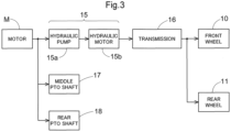
- the tractor includes a hydraulic continuously variable transmission 15 and a transmission 16.
- the hydraulic continuously variable transmission 15 includes a hydraulic pump 15a and a hydraulic motor 15b.
- the hydraulic pump 15a is driven by rotational motive power transmitted from the motor M. As a result of the hydraulic pump 15a being driven, rotational motive power is output from the hydraulic motor 15b.
- the hydraulic continuously variable transmission 15 is configured to change the speed of rotational motive power between the hydraulic pump 15a and the hydraulic motor 15b. Also, the hydraulic continuously variable transmission 15 is configured to be capable of changing the transmission ratio in a stepless manner.
- the rotational motive power output from the hydraulic motor 15b is transmitted to the transmission 16.
- the speed of the rotational motive power transmitted to the transmission 16 is changed by a gear transmission mechanism included in the transmission 16, and the rotational motive power is distributed to the left and right front wheels 10 and the left and right rear wheels 11.
- the left and right front wheels 10 and the left and right rear wheels 11 are driven.
- the tractor also includes a middle PTO shaft 17 and a rear PTO shaft 18.
- Rotational motive power output from the motor M is distributed to the hydraulic pump 15a, the middle PTO shaft 17, and the rear PTO shaft 18.
- the middle PTO shaft 17 and the rear PTO shaft 18 are rotated by the distributed rotational motive power.
- a work device is connected to the middle PTO shaft 17 or the rear PTO shaft 18, the work device is driven by rotational motive power transmitted by the middle PTO shaft 17 or the rear PTO shaft 18.
- a grass cutting device 19 is connected to the middle PTO shaft 17 as shown in FIG. 2 .
- the grass cutting device 19 is driven by rotational motive power transmitted by the middle PTO shaft 17.
- the motor M is behind the inverter 14.
- the motor M and the inverter 14 are below the battery 4 for driving.
- the motor M and the inverter 14 are aligned in the front-rear direction of the body. Specifically, the motor M and the inverter 14 are aligned in the front-rear direction of the body such that the inverter 14 is on the front side and the motor M is on the rear side.
- the tractor includes a radiator 20, a DC (direct current)-DC converter 21, and a battery 22.
- the radiator 20, the DC-DC converter 21, and the battery 22 are in front of the battery 4 for driving.
- the DC-DC converter 21 is to the immediate right of the radiator 20.
- the battery 22 is to the immediate right of the DC-DC converter 21.
- the radiator 20 cools cooling water for cooling the inverter 14, the motor M, and the DC-DC converter 21.
- a cooling hose 23 is connected to a lower portion of the radiator 20 and extends toward the inverter 14.
- the DC-DC converter 21 steps down electric power supplied from the battery 4 for driving.
- the battery 22 is for supplying electric power to various electric components.
- the electric power (high voltage) supplied from the battery 4 for driving is stepped down by the DC-DC converter 21 before being used to charge the battery 22 as low-voltage electric power.
- a first harness 24 connecting the battery 4 for driving and the DC-DC converter 21 extends from the battery 4 for driving to the DC-DC converter 21.
- the first harness 24 is for supplying electric power from the battery 4 for driving to the DC-DC converter 21.
- An output section 4a to which the first harness 24 is connected is provided at an upper portion of a front surface of the battery 4 for driving.
- An input section 21a to which the first harness 24 is connected is provided at a front portion of a lower surface of the DC-DC converter 21.
- the first harness 24 is routed in such a manner as to extend downward from the output section 4a and forward toward the input section 21a.
- a second harness 25 connecting the inverter 14 and the motor M extends from the inverter 14 to the motor M.
- the second harness 25 is for supplying electric power from the inverter 14 to the motor M.
- An output section 14a to which the second harness 25 is connected is provided at a front portion of a lower surface of the inverter 14.
- An input section Ma to which the second harness 25 is connected is provided at a front end of the motor M.
- the second harness 25 is routed in such a manner as to extend rearward from the output section 14a toward the input section Ma.
- the body frame 2 includes left and right side plates 40, left and right bases 41, a front plate 42, a rear plate 43, a bottom plate 44, and a lateral plate 45.
- the left and right side plates 40 are spaced apart from each other in the left-right direction of the body.
- a space between the left side plate 40 and the right side plate 40 is used as a space in which the motor M is disposed.
- the radiator 20, the DC-DC converter 21, and the battery 22 are supported on a base 46.
- the base 46 is supported on front portions of the left and right side plates 40.
- the left base 41 extends leftward from an upper edge of the left side plate 40.
- the right base 41 extends rightward from an upper edge of the right side plate 40.
- the inverter 14 is supported on the left and right bases 41.
- the battery 4 for driving is supported on a support stand 47.
- the support stand 47 is supported on the left and right bases 41 and the rear plate 43.
- the front plate 42 extends from a front end of the left side plate 40 to a front end of the right side plate 40.
- the rear plate 43 extends from a rear end of the left side plate 40 to a rear end of the right side plate 40.
- the motor M is supported by the rear plate 43.
- the bottom plate 44 extends from a lower edge of the left side plate 40 to a lower edge of the right side plate 40.
- the lateral plate 45 is behind the bottom plate 44 and extends from the left side plate 40 to the right side plate 40.
- a first opening O1 is formed in a portion of the body frame 2 surrounded by the front plate 42, a front edge of the bottom plate 44, and the left and right side plates 40.
- a second opening O2 is formed in a portion of the bottom plate 44 below a rear portion of the second harness 25.
- a third opening O3 is formed in a portion of the body frame 2 surrounded by the rear plate 43, a rear edge of the bottom plate 44, and the left and right side plates 40. That is, the body frame 2 has the first opening O1, the second opening O2, and the third opening O3.
- the first opening O1 is configured to expose the first harness 24 and the cooling hose 23 in the downward direction.
- the second opening O2 is configured to expose the second harness 25 in the downward direction.
- the third opening O3 is configured to expose the motor M (specifically, a portion (water-cooled portion) Mb of the motor M in which cooling water flows) in the downward direction.
- a first cover member 48, a second cover member 49, and a third cover member 50 are attached to the body frame 2.
- the first cover member 48 is configured to cover the first opening O1. More specifically, the first cover member 48 is configured to cover a portion of the first harness 24 exposed downward through the first opening O1 and a portion of the cooling hose 23 exposed downward through the first opening O1. The portion of the first harness 24 exposed downward through the first opening O1 and the portion of the cooling hose 23 exposed downward through the first opening O1 are covered by the first cover member 48 from below.
- the first cover member 48 includes a horizontal surface portion 48a, left and right bent portions 48b, and recessed portions 48c.
- the bent portions 48b have shapes that are bent upward relative to the horizontal surface portion 48a in such a manner as to extend along the respective side plates 40.
- the recessed portions 48c are configured to accommodate therein members (e.g., a member supporting a front portion of the grass cutting device 19) around the first cover member 48, and thus, the first cover member 48 does not obstruct the members around the first cover member 48.
- the first cover member 48 is fixed to the left and right side plates 40 by a plurality of bolts 51. Specifically, each bent portion 48b is pressed against the corresponding side plate 40 from the lateral outer side and is fixed to the side plate 40 by a plurality of (two in the present embodiment) bolts 51.
- the second cover member 49 is configured to cover the second opening O2. More specifically, the second cover member 49 is configured to cover a portion of the second harness 25 exposed downward through the second opening O2. The portion of the second harness 25 exposed downward through the second opening O2 is covered by the second cover member 49 from below.
- the second cover member 49 has a plurality of (four in the present embodiment) drain holes 49a.
- the drain holes 49a are formed in a portion of the second cover member 49 that faces the second opening O2.
- the second cover member 49 is pressed against the bottom plate 44 from below and is fixed to the bottom plate 44 by a plurality of (four in the present embodiment) bolts 52.
- the third cover member 50 is configured to cover the third opening O3. More specifically, the third cover member 50 is configured to cover a portion of the motor M exposed downward through the third opening O3. In the present embodiment, the third cover member 50 is configured to cover the water-cooled portion Mb of the motor M. The portion (water-cooled portion Mb) of the motor M exposed downward through the third opening O3 is covered by the third cover member 50 from below.
- the third cover member 50 is configured to partially cover the third opening O3. A portion of the third opening O3 between a front edge of the third cover member 50 and the rear edge of the bottom plate 44 and a portion of the third opening O3 between a rear edge of the third cover member 50 and the rear plate 43 are not covered by the third cover member 50.
- the third cover member 50 is pressed against the lateral plate 45 from below and is fixed to the lateral plate 45 by a plurality of (two in the present embodiment) bolts 53.
- a transmission shaft 54 for transmitting motive power from the motor M (motive power from the transmission 16) to the left and right front wheels 10 is provided below the bottom plate 44.
- the transmission shaft 54 is held by the third cover member 50 via a stay 55.
- the present invention is applicable to not only a tractor but also a combine harvester, a rice transplanter, and a utility vehicle (multipurpose vehicle).
Landscapes
- Engineering & Computer Science (AREA)
- Transportation (AREA)
- Mechanical Engineering (AREA)
- Life Sciences & Earth Sciences (AREA)
- Sustainable Development (AREA)
- Sustainable Energy (AREA)
- Power Engineering (AREA)
- Chemical & Material Sciences (AREA)
- Combustion & Propulsion (AREA)
- Arrangement Or Mounting Of Propulsion Units For Vehicles (AREA)
- Electric Propulsion And Braking For Vehicles (AREA)
- Agricultural Machines (AREA)
Abstract
Description
- The present invention relates to an electric work vehicle.
- A known example of an electric work vehicle is disclosed in
Patent Document 1. The electric work vehicle disclosed inPatent Document 1 includes a battery ("travel battery (4)" in the document), an inverter ("inverter (14)" in the document) configured to convert DC power from the battery to AC power, a motor ("motor (M)" in the document) driven by electric power supplied from the inverter, a travel device ("front wheels (10) and rear wheels (11)" in the document) driven by the motor, and a DC-DC converter ("voltage converter (19)" in the document) configured to step down electric power from the battery. - Patent Document 1:
JP 2021-953A - In an electric work vehicle such as that as described above, usually, the battery and the DC-DC converter are connected to each other by a harness, and the inverter and the motor are connected to each other by a harness. For such an electric work vehicle, it is desired to facilitate the maintenance of the harnesses and the motor and to prevent the harnesses and the motor from being damaged by a flying stone from the ground.
- Under these circumstances, there is demand for an electric work vehicle that provides enhanced ease of maintenance of the harnesses and the motor and is configured to prevent the harnesses and the motor from being damaged by a flying stone from the ground.
- A feature of the present invention lies in a configuration including: a battery; an inverter configured to convert DC power from the battery to AC power; a motor drivable by electric power supplied from the inverter; a travel device drivable by the motor; a DC-DC converter configured to step down electric power from the battery; a first harness connecting the battery and the DC-DC converter; a second harness connecting the inverter and the motor; a body frame having a first opening through which the first harness is exposed downward, a second opening through which the second harness is exposed downward, and a third opening through which the motor is exposed downward, and supporting the battery, the inverter, the motor, and the DC-DC converter; a first cover member configured to cover a portion of the first harness exposed downward through the first opening and configured to be removable; a second cover member configured to cover a portion of the second harness exposed downward through the second opening and configured to be removable; and a third cover member configured to cover a portion of the motor exposed downward through the third opening and configured to be removable.
- With this characteristic configuration, even when a stone flies from the ground toward the first harness, the second harness, or the motor, the stone is blocked by the first cover member, the second cover member, or the third cover member. Thus, the first harness, the second harness, and the motor can be prevented from being damaged by a flying stone from the ground.
- In addition, during maintenance, the first cover member, the second cover member, and the third cover member are removed, and the first harness, the second harness, and the motor are thus exposed downward. As a result, it is easy to perform the maintenance of the first harness, the second harness, and the motor by accessing the first harness, the second harness, and the motor from below.
- Furthermore, in the present invention, it is preferable that the motor is configured as a water-cooled type, and the third cover member is configured to cover a water-cooled portion of the motor.
- With this characteristic configuration, the water-cooled portion of the motor can be protected by the third cover member.
- Furthermore, in the present invention, it is preferable that at least any of the first cover member, the second cover member, or the third cover member has a drain hole.
- With this characteristic configuration, at least any of the first cover member, the second cover member, or the second cover member allows water accumulating inside to be discharged through the drain hole.
- Furthermore, in the present invention, it is preferable that a transmission shaft configured to transmit motive power from the motor to the travel device is provided, and the transmission shaft is held by at least any of the first cover member, the second cover member, or the third cover member.
- With this characteristic configuration, at least any of the first cover member, the second cover member, or the second cover member can be used as a support for the transmission shaft.
-
-
FIG. 1 is a left side view of a tractor. -
FIG. 2 is a left side view showing arrangement of an inverter and the like. -
FIG. 3 is a diagram showing a flow of motive power transmission. -
FIG. 4 is a left side sectional view showing a configuration of a front portion of a body of the tractor. -
FIG. 5 is a plan view showing the configuration of the front portion of the body of the tractor. -
FIG. 6 is a bottom view showing the configuration of the front portion of the body of the tractor. - An embodiment of the present invention will be described based on the drawings. In the following description, unless otherwise stated, the direction of an arrow F and the direction of an arrow B in the drawings will be respectively referred to as "the front side" and "the rear side", and the direction of an arrow L and the direction of an arrow R in the drawings will be respectively referred to as "the left side" and "the right side". Also, the direction of an arrow U and the direction of an arrow D in the drawings will be respectively referred to as "the upper side" and "the lower side".
- The following describes a tractor according to the present embodiment. As shown in
FIG. 1 , the tractor includes left and rightfront wheels 10, left and rightrear wheels 11, and acover member 12. - The tractor also includes a
body frame 2 and adriving section 3. Thebody frame 2 is supported by the left and rightfront wheels 10 and the left and rightrear wheels 11. - The
cover member 12 is disposed in a front portion of the body of the tractor. Thedriving section 3 is behind thecover member 12. In other words, thecover member 12 is in front of thedriving section 3. - The
driving section 3 includes aprotective frame 30, a driver'sseat 31, and asteering wheel 32. An operator can sit on the driver'sseat 31. Accordingly, the operator can get on thedriving section 3. The operator steers the left and rightfront wheels 10 by operating thesteering wheel 32. The operator can perform various driving operations in thedriving section 3. - The tractor includes a
battery 4 for driving. Thecover member 12 is configured to be pivotable about an opening/closing axis Q extending in the left-right direction of the body. Accordingly, thecover member 12 is configured to be openable and closable. When thecover member 12 is closed, thebattery 4 for driving is covered by thecover member 12. - As shown in
FIG. 2 , the tractor includes aninverter 14 and a motor M. Thebattery 4 for driving supplies electric power to theinverter 14. Theinverter 14 converts DC power supplied from thebattery 4 for driving to AC power, and supplies the AC power to the motor M. The motor M is driven by the AC power supplied from theinverter 14. - As shown in
FIGS. 2 and3 , the tractor includes a hydraulic continuouslyvariable transmission 15 and atransmission 16. As shown inFIG. 3 , the hydraulic continuouslyvariable transmission 15 includes ahydraulic pump 15a and ahydraulic motor 15b. - The
hydraulic pump 15a is driven by rotational motive power transmitted from the motor M. As a result of thehydraulic pump 15a being driven, rotational motive power is output from thehydraulic motor 15b. The hydraulic continuouslyvariable transmission 15 is configured to change the speed of rotational motive power between thehydraulic pump 15a and thehydraulic motor 15b. Also, the hydraulic continuouslyvariable transmission 15 is configured to be capable of changing the transmission ratio in a stepless manner. - The rotational motive power output from the
hydraulic motor 15b is transmitted to thetransmission 16. The speed of the rotational motive power transmitted to thetransmission 16 is changed by a gear transmission mechanism included in thetransmission 16, and the rotational motive power is distributed to the left and rightfront wheels 10 and the left and rightrear wheels 11. Thus, the left and rightfront wheels 10 and the left and rightrear wheels 11 are driven. - As shown in
FIGS. 2 and3 , the tractor also includes amiddle PTO shaft 17 and arear PTO shaft 18. Rotational motive power output from the motor M is distributed to thehydraulic pump 15a, themiddle PTO shaft 17, and therear PTO shaft 18. Themiddle PTO shaft 17 and therear PTO shaft 18 are rotated by the distributed rotational motive power. - If a work device is connected to the
middle PTO shaft 17 or therear PTO shaft 18, the work device is driven by rotational motive power transmitted by themiddle PTO shaft 17 or therear PTO shaft 18. For example, in the present embodiment, agrass cutting device 19 is connected to themiddle PTO shaft 17 as shown inFIG. 2 . Thegrass cutting device 19 is driven by rotational motive power transmitted by themiddle PTO shaft 17. - As shown in
FIGS. 4 to 6 , the motor M is behind theinverter 14. The motor M and theinverter 14 are below thebattery 4 for driving. The motor M and theinverter 14 are aligned in the front-rear direction of the body. Specifically, the motor M and theinverter 14 are aligned in the front-rear direction of the body such that theinverter 14 is on the front side and the motor M is on the rear side. - The tractor includes a
radiator 20, a DC (direct current)-DC converter 21, and abattery 22. Theradiator 20, the DC-DC converter 21, and thebattery 22 are in front of thebattery 4 for driving. The DC-DC converter 21 is to the immediate right of theradiator 20. Thebattery 22 is to the immediate right of the DC-DC converter 21. - Here, all the
inverter 14, the motor M, and the DC-DC converter 21 are water-cooled types. Theradiator 20 cools cooling water for cooling theinverter 14, the motor M, and the DC-DC converter 21. A coolinghose 23 is connected to a lower portion of theradiator 20 and extends toward theinverter 14. The DC-DC converter 21 steps down electric power supplied from thebattery 4 for driving. Thebattery 22 is for supplying electric power to various electric components. The electric power (high voltage) supplied from thebattery 4 for driving is stepped down by the DC-DC converter 21 before being used to charge thebattery 22 as low-voltage electric power. - As shown in
FIGS. 4 to 6 , afirst harness 24 connecting thebattery 4 for driving and the DC-DC converter 21 extends from thebattery 4 for driving to the DC-DC converter 21. Thefirst harness 24 is for supplying electric power from thebattery 4 for driving to the DC-DC converter 21. Anoutput section 4a to which thefirst harness 24 is connected is provided at an upper portion of a front surface of thebattery 4 for driving. Aninput section 21a to which thefirst harness 24 is connected is provided at a front portion of a lower surface of the DC-DC converter 21. Thefirst harness 24 is routed in such a manner as to extend downward from theoutput section 4a and forward toward theinput section 21a. - A
second harness 25 connecting theinverter 14 and the motor M extends from theinverter 14 to the motor M. Thesecond harness 25 is for supplying electric power from theinverter 14 to the motor M.An output section 14a to which thesecond harness 25 is connected is provided at a front portion of a lower surface of theinverter 14. An input section Ma to which thesecond harness 25 is connected is provided at a front end of the motor M. Thesecond harness 25 is routed in such a manner as to extend rearward from theoutput section 14a toward the input section Ma. - As shown in
FIGS. 4 to 6 , thebody frame 2 includes left andright side plates 40, left andright bases 41, afront plate 42, arear plate 43, abottom plate 44, and alateral plate 45. The left andright side plates 40 are spaced apart from each other in the left-right direction of the body. A space between theleft side plate 40 and theright side plate 40 is used as a space in which the motor M is disposed. Theradiator 20, the DC-DC converter 21, and thebattery 22 are supported on abase 46. Thebase 46 is supported on front portions of the left andright side plates 40. - The
left base 41 extends leftward from an upper edge of theleft side plate 40. Theright base 41 extends rightward from an upper edge of theright side plate 40. Theinverter 14 is supported on the left and right bases 41. Thebattery 4 for driving is supported on asupport stand 47. The support stand 47 is supported on the left andright bases 41 and therear plate 43. - The
front plate 42 extends from a front end of theleft side plate 40 to a front end of theright side plate 40. Therear plate 43 extends from a rear end of theleft side plate 40 to a rear end of theright side plate 40. The motor M is supported by therear plate 43. Thebottom plate 44 extends from a lower edge of theleft side plate 40 to a lower edge of theright side plate 40. Thelateral plate 45 is behind thebottom plate 44 and extends from theleft side plate 40 to theright side plate 40. - A first opening O1 is formed in a portion of the
body frame 2 surrounded by thefront plate 42, a front edge of thebottom plate 44, and the left andright side plates 40. A second opening O2 is formed in a portion of thebottom plate 44 below a rear portion of thesecond harness 25. A third opening O3 is formed in a portion of thebody frame 2 surrounded by therear plate 43, a rear edge of thebottom plate 44, and the left andright side plates 40. That is, thebody frame 2 has the first opening O1, the second opening O2, and the third opening O3. - The first opening O1 is configured to expose the
first harness 24 and the coolinghose 23 in the downward direction. The second opening O2 is configured to expose thesecond harness 25 in the downward direction. The third opening O3 is configured to expose the motor M (specifically, a portion (water-cooled portion) Mb of the motor M in which cooling water flows) in the downward direction. - As shown in
FIGS. 4 to 6 , afirst cover member 48, asecond cover member 49, and athird cover member 50 are attached to thebody frame 2. Thefirst cover member 48 is configured to cover the first opening O1. More specifically, thefirst cover member 48 is configured to cover a portion of thefirst harness 24 exposed downward through the first opening O1 and a portion of the coolinghose 23 exposed downward through the first opening O1. The portion of thefirst harness 24 exposed downward through the first opening O1 and the portion of the coolinghose 23 exposed downward through the first opening O1 are covered by thefirst cover member 48 from below. - The
first cover member 48 includes ahorizontal surface portion 48a, left and rightbent portions 48b, and recessedportions 48c. Thebent portions 48b have shapes that are bent upward relative to thehorizontal surface portion 48a in such a manner as to extend along therespective side plates 40. The recessedportions 48c are configured to accommodate therein members (e.g., a member supporting a front portion of the grass cutting device 19) around thefirst cover member 48, and thus, thefirst cover member 48 does not obstruct the members around thefirst cover member 48. Thefirst cover member 48 is fixed to the left andright side plates 40 by a plurality ofbolts 51. Specifically, eachbent portion 48b is pressed against thecorresponding side plate 40 from the lateral outer side and is fixed to theside plate 40 by a plurality of (two in the present embodiment)bolts 51. - The
second cover member 49 is configured to cover the second opening O2. More specifically, thesecond cover member 49 is configured to cover a portion of thesecond harness 25 exposed downward through the second opening O2. The portion of thesecond harness 25 exposed downward through the second opening O2 is covered by thesecond cover member 49 from below. - The
second cover member 49 has a plurality of (four in the present embodiment)drain holes 49a. The drain holes 49a are formed in a portion of thesecond cover member 49 that faces the second opening O2. Thesecond cover member 49 is pressed against thebottom plate 44 from below and is fixed to thebottom plate 44 by a plurality of (four in the present embodiment)bolts 52. - The
third cover member 50 is configured to cover the third opening O3. More specifically, thethird cover member 50 is configured to cover a portion of the motor M exposed downward through the third opening O3. In the present embodiment, thethird cover member 50 is configured to cover the water-cooled portion Mb of the motor M. The portion (water-cooled portion Mb) of the motor M exposed downward through the third opening O3 is covered by thethird cover member 50 from below. - In the present embodiment, the
third cover member 50 is configured to partially cover the third opening O3. A portion of the third opening O3 between a front edge of thethird cover member 50 and the rear edge of thebottom plate 44 and a portion of the third opening O3 between a rear edge of thethird cover member 50 and therear plate 43 are not covered by thethird cover member 50. Thethird cover member 50 is pressed against thelateral plate 45 from below and is fixed to thelateral plate 45 by a plurality of (two in the present embodiment)bolts 53. - Here, a
transmission shaft 54 for transmitting motive power from the motor M (motive power from the transmission 16) to the left and rightfront wheels 10 is provided below thebottom plate 44. Thetransmission shaft 54 is held by thethird cover member 50 via astay 55. -
- (1) In the above-described embodiment, the
first cover member 48 is configured to partially cover the first opening O1. However, thefirst cover member 48 may be configured to cover the entire first opening O1. - (2) In the above-described embodiment, the
second cover member 49 is configured to cover the entire second opening O2. However, thesecond cover member 49 may be configured to partially cover the second opening O2. - (3) In the present embodiment, the
third cover member 50 is configured to partially cover the third opening O3. However, thethird cover member 50 may be configured to cover the entire third opening O3. - (4) In the above-described embodiment, the
third cover member 50 is configured to cover the water-cooled portion Mb of the motor M. However, thethird cover member 50 may be configured to cover a portion other than the water-cooled portion Mb of the motor M, in addition to the water-cooled portion Mb of the motor M. - (5) In the above-described embodiment, the
second cover member 49 has the fourdrain holes 49a. However, thefirst cover member 48 may have one to three, or five or more, drainholes 49a. - (6) In the above-described embodiment, the
transmission shaft 54 is held by thethird cover member 50. However, thetransmission shaft 54 may be held by thesecond cover member 49 instead of thethird cover member 50 or together with thethird cover member 50. - The present invention is applicable to not only a tractor but also a combine harvester, a rice transplanter, and a utility vehicle (multipurpose vehicle).
-
- 2: Body frame
- 4: Battery for driving (battery)
- 10: Front wheel (travel device)
- 11: Rear wheel (travel device)
- 14: Inverter
- 21: DC-DC converter
- 24: First harness
- 25: Second harness
- 48: First cover member
- 49: Second cover member
- 49a: Drain hole
- 50: Third cover member
- 54: Transmission shaft
- M: Motor
- Mb: Water-cooled portion
- O1: First opening
- O2: Second opening
- O3: Third opening
Claims (4)
- An electric work vehicle comprising:a battery (4);an inverter (14) configured to convert DC power from the battery (4) to AC power;a motor (M) drivable by electric power supplied from the inverter (14);a travel device (10, 11) drivable by the motor (M);a DC-DC converter (21) configured to step down electric power from the battery (4);a first harness (24) connecting the battery (4) and the DC-DC converter (21);a second harness (25) connecting the inverter (14) and the motor (M);a body frame (2) having a first opening (O1) through which the first harness (24) is exposed downward, a second opening (O2) through which the second harness (25) is exposed downward, and a third opening (O3) through which the motor (M) is exposed downward, and supporting the battery (4), the inverter (14), the motor (M), and the DC-DC converter (21);a first cover member (48) configured to cover a portion of the first harness (24) exposed downward through the first opening (O1) and configured to be removable;a second cover member (49) configured to cover a portion of the second harness (25) exposed downward through the second opening (O2) and configured to be removable; anda third cover member (50) configured to cover a portion of the motor (M) exposed downward through the third opening (O3) and configured to be removable.
- The electric work vehicle according to claim 1,wherein the motor (M) is configured as a water-cooled type, andthe third cover member (50) is configured to cover a water-cooled portion (Mb) of the motor (M).
- The electric work vehicle according to claim 1 or 2,
wherein at least any of the first cover member (48), the second cover member (49), or the third cover member (50) has a drain hole (49a). - The electric work vehicle according to any one of claims 1 to 3, comprising:a transmission shaft (54) configured to transmit motive power from the motor (M) to the travel device (10, 11),wherein the transmission shaft (54) is held by at least any of the first cover member (48), the second cover member (49), or the third cover member (50).
Applications Claiming Priority (2)
| Application Number | Priority Date | Filing Date | Title |
|---|---|---|---|
| JP2021213186A JP7515451B2 (en) | 2021-12-27 | 2021-12-27 | Electric work vehicle |
| PCT/JP2022/038590 WO2023127229A1 (en) | 2021-12-27 | 2022-10-17 | Electric work vehicle |
Publications (2)
| Publication Number | Publication Date |
|---|---|
| EP4458596A1 true EP4458596A1 (en) | 2024-11-06 |
| EP4458596A4 EP4458596A4 (en) | 2025-12-31 |
Family
ID=86998573
Family Applications (1)
| Application Number | Title | Priority Date | Filing Date |
|---|---|---|---|
| EP22915464.6A Pending EP4458596A4 (en) | 2021-12-27 | 2022-10-17 | ELECTRIC WORK VEHICLE |
Country Status (4)
| Country | Link |
|---|---|
| US (1) | US12409740B2 (en) |
| EP (1) | EP4458596A4 (en) |
| JP (2) | JP7515451B2 (en) |
| WO (1) | WO2023127229A1 (en) |
Families Citing this family (1)
| Publication number | Priority date | Publication date | Assignee | Title |
|---|---|---|---|---|
| JP7498683B2 (en) * | 2021-06-29 | 2024-06-12 | 株式会社クボタ | Electric work vehicle |
Family Cites Families (16)
| Publication number | Priority date | Publication date | Assignee | Title |
|---|---|---|---|---|
| JPH092080A (en) * | 1995-06-19 | 1997-01-07 | Toyota Autom Loom Works Ltd | Wiring structure of battery industrial vehicle |
| JPH11180163A (en) * | 1997-12-18 | 1999-07-06 | Honda Motor Co Ltd | Electric car |
| US6598691B2 (en) | 1997-12-18 | 2003-07-29 | Honda Giken Kogyo Kabushiki Kaisha | Electric vehicle |
| JP5189040B2 (en) * | 2009-07-17 | 2013-04-24 | 住友建機株式会社 | Construction machinery |
| JP2011121763A (en) * | 2009-12-14 | 2011-06-23 | Kyokuto Kaihatsu Kogyo Co Ltd | Refuse collecting vehicle |
| JP5985918B2 (en) * | 2012-07-27 | 2016-09-06 | 株式会社クボタ | Work vehicle body structure |
| JP6605347B2 (en) * | 2016-02-04 | 2019-11-13 | 本田技研工業株式会社 | 4 wheel vehicle |
| JP2018105393A (en) * | 2016-12-26 | 2018-07-05 | 三菱自動車工業株式会社 | Cover seal structure and battery pack |
| JP6963867B2 (en) * | 2017-04-04 | 2021-11-10 | 株式会社ソミックマネージメントホールディングス | Multipurpose platform |
| JP6851260B2 (en) * | 2017-05-24 | 2021-03-31 | 株式会社クボタ | Electric work vehicle |
| JP7154480B2 (en) * | 2018-11-22 | 2022-10-18 | マツダ株式会社 | battery cooler |
| US11148518B2 (en) * | 2018-12-26 | 2021-10-19 | Kubota Corporation | Electric work vehicle arrangement |
| US11273716B2 (en) * | 2019-03-12 | 2022-03-15 | Kubota Corporation | Electric work vehicle |
| JP7178955B2 (en) * | 2019-05-14 | 2022-11-28 | 株式会社クボタ | Battery pack for electric work vehicle |
| JP7224245B2 (en) | 2019-06-24 | 2023-02-17 | 株式会社クボタ | electric work vehicle |
| US20210316713A1 (en) * | 2020-04-09 | 2021-10-14 | Deere & Company | System and method for runtime planning of an electric battery powered work vehicle |
-
2021
- 2021-12-27 JP JP2021213186A patent/JP7515451B2/en active Active
-
2022
- 2022-10-17 EP EP22915464.6A patent/EP4458596A4/en active Pending
- 2022-10-17 WO PCT/JP2022/038590 patent/WO2023127229A1/en not_active Ceased
-
2024
- 2024-06-05 US US18/734,667 patent/US12409740B2/en active Active
- 2024-07-01 JP JP2024105940A patent/JP7720960B2/en active Active
Also Published As
| Publication number | Publication date |
|---|---|
| WO2023127229A1 (en) | 2023-07-06 |
| JP2023097054A (en) | 2023-07-07 |
| US12409740B2 (en) | 2025-09-09 |
| JP7515451B2 (en) | 2024-07-12 |
| EP4458596A4 (en) | 2025-12-31 |
| US20240317074A1 (en) | 2024-09-26 |
| JP2024114948A (en) | 2024-08-23 |
| JP7720960B2 (en) | 2025-08-08 |
Similar Documents
| Publication | Publication Date | Title |
|---|---|---|
| EP3987902B1 (en) | Electric work vehicle | |
| JP7662718B2 (en) | Electric work vehicle | |
| EP3988432B1 (en) | Electric work vehicle | |
| JP7321008B2 (en) | electric work vehicle | |
| JP2021104768A (en) | Electric work vehicle | |
| EP4456369A1 (en) | Electric work vehicle | |
| US12409740B2 (en) | Electric work vehicle | |
| EP4454447A1 (en) | Electric work vehicle | |
| EP4454915A1 (en) | Electric work vehicle | |
| EP4364988A1 (en) | Electric work vehicle | |
| EP4342707A1 (en) | Work vehicle | |
| EP4456404A1 (en) | Electric work vehicle | |
| JP2023112412A (en) | electric work vehicle | |
| JP2023095638A (en) | electric work vehicle | |
| EP3289851A1 (en) | Work vehicle | |
| EP4454914A1 (en) | Electric work vehicle | |
| EP4454913A1 (en) | Electric work vehicle | |
| EP4516551A2 (en) | Work vehicle | |
| JP7555326B2 (en) | Electric work vehicle | |
| WO2025142202A1 (en) | Electric tractor | |
| WO2025142186A1 (en) | Electric tractor |
Legal Events
| Date | Code | Title | Description |
|---|---|---|---|
| STAA | Information on the status of an ep patent application or granted ep patent |
Free format text: STATUS: THE INTERNATIONAL PUBLICATION HAS BEEN MADE |
|
| PUAI | Public reference made under article 153(3) epc to a published international application that has entered the european phase |
Free format text: ORIGINAL CODE: 0009012 |
|
| STAA | Information on the status of an ep patent application or granted ep patent |
Free format text: STATUS: REQUEST FOR EXAMINATION WAS MADE |
|
| 17P | Request for examination filed |
Effective date: 20240606 |
|
| AK | Designated contracting states |
Kind code of ref document: A1 Designated state(s): AL AT BE BG CH CY CZ DE DK EE ES FI FR GB GR HR HU IE IS IT LI LT LU LV MC ME MK MT NL NO PL PT RO RS SE SI SK SM TR |
|
| DAV | Request for validation of the european patent (deleted) | ||
| DAX | Request for extension of the european patent (deleted) | ||
| A4 | Supplementary search report drawn up and despatched |
Effective date: 20251201 |
|
| RIC1 | Information provided on ipc code assigned before grant |
Ipc: B60K 1/00 20060101AFI20251125BHEP Ipc: B60K 1/04 20190101ALI20251125BHEP Ipc: B60L 50/60 20190101ALI20251125BHEP Ipc: B62D 21/18 20060101ALI20251125BHEP Ipc: B62D 49/00 20060101ALI20251125BHEP |