EP4458538A1 - Verfahren zum herstellen eines holzwerkstoffs und holzwerkstoff-herstellvorrichtung - Google Patents
Verfahren zum herstellen eines holzwerkstoffs und holzwerkstoff-herstellvorrichtung Download PDFInfo
- Publication number
- EP4458538A1 EP4458538A1 EP23171473.4A EP23171473A EP4458538A1 EP 4458538 A1 EP4458538 A1 EP 4458538A1 EP 23171473 A EP23171473 A EP 23171473A EP 4458538 A1 EP4458538 A1 EP 4458538A1
- Authority
- EP
- European Patent Office
- Prior art keywords
- wood
- voc
- exhaust air
- oxidizing agent
- concentration
- Prior art date
- Legal status (The legal status is an assumption and is not a legal conclusion. Google has not performed a legal analysis and makes no representation as to the accuracy of the status listed.)
- Pending
Links
Images


Classifications
-
- B—PERFORMING OPERATIONS; TRANSPORTING
- B27—WORKING OR PRESERVING WOOD OR SIMILAR MATERIAL; NAILING OR STAPLING MACHINES IN GENERAL
- B27N—MANUFACTURE BY DRY PROCESSES OF ARTICLES, WITH OR WITHOUT ORGANIC BINDING AGENTS, MADE FROM PARTICLES OR FIBRES CONSISTING OF WOOD OR OTHER LIGNOCELLULOSIC OR LIKE ORGANIC MATERIAL
- B27N1/00—Pretreatment of moulding material
- B27N1/003—Pretreatment of moulding material for reducing formaldehyde gas emission
-
- B—PERFORMING OPERATIONS; TRANSPORTING
- B27—WORKING OR PRESERVING WOOD OR SIMILAR MATERIAL; NAILING OR STAPLING MACHINES IN GENERAL
- B27N—MANUFACTURE BY DRY PROCESSES OF ARTICLES, WITH OR WITHOUT ORGANIC BINDING AGENTS, MADE FROM PARTICLES OR FIBRES CONSISTING OF WOOD OR OTHER LIGNOCELLULOSIC OR LIKE ORGANIC MATERIAL
- B27N1/00—Pretreatment of moulding material
-
- B—PERFORMING OPERATIONS; TRANSPORTING
- B27—WORKING OR PRESERVING WOOD OR SIMILAR MATERIAL; NAILING OR STAPLING MACHINES IN GENERAL
- B27N—MANUFACTURE BY DRY PROCESSES OF ARTICLES, WITH OR WITHOUT ORGANIC BINDING AGENTS, MADE FROM PARTICLES OR FIBRES CONSISTING OF WOOD OR OTHER LIGNOCELLULOSIC OR LIKE ORGANIC MATERIAL
- B27N1/00—Pretreatment of moulding material
- B27N1/02—Mixing the material with binding agent
- B27N1/029—Feeding; Proportioning; Controlling
-
- B—PERFORMING OPERATIONS; TRANSPORTING
- B27—WORKING OR PRESERVING WOOD OR SIMILAR MATERIAL; NAILING OR STAPLING MACHINES IN GENERAL
- B27N—MANUFACTURE BY DRY PROCESSES OF ARTICLES, WITH OR WITHOUT ORGANIC BINDING AGENTS, MADE FROM PARTICLES OR FIBRES CONSISTING OF WOOD OR OTHER LIGNOCELLULOSIC OR LIKE ORGANIC MATERIAL
- B27N3/00—Manufacture of substantially flat articles, e.g. boards, from particles or fibres
- B27N3/007—Manufacture of substantially flat articles, e.g. boards, from particles or fibres and at least partly composed of recycled material
-
- B—PERFORMING OPERATIONS; TRANSPORTING
- B27—WORKING OR PRESERVING WOOD OR SIMILAR MATERIAL; NAILING OR STAPLING MACHINES IN GENERAL
- B27N—MANUFACTURE BY DRY PROCESSES OF ARTICLES, WITH OR WITHOUT ORGANIC BINDING AGENTS, MADE FROM PARTICLES OR FIBRES CONSISTING OF WOOD OR OTHER LIGNOCELLULOSIC OR LIKE ORGANIC MATERIAL
- B27N3/00—Manufacture of substantially flat articles, e.g. boards, from particles or fibres
- B27N3/02—Manufacture of substantially flat articles, e.g. boards, from particles or fibres from particles
-
- B—PERFORMING OPERATIONS; TRANSPORTING
- B27—WORKING OR PRESERVING WOOD OR SIMILAR MATERIAL; NAILING OR STAPLING MACHINES IN GENERAL
- B27N—MANUFACTURE BY DRY PROCESSES OF ARTICLES, WITH OR WITHOUT ORGANIC BINDING AGENTS, MADE FROM PARTICLES OR FIBRES CONSISTING OF WOOD OR OTHER LIGNOCELLULOSIC OR LIKE ORGANIC MATERIAL
- B27N3/00—Manufacture of substantially flat articles, e.g. boards, from particles or fibres
- B27N3/04—Manufacture of substantially flat articles, e.g. boards, from particles or fibres from fibres
-
- B—PERFORMING OPERATIONS; TRANSPORTING
- B27—WORKING OR PRESERVING WOOD OR SIMILAR MATERIAL; NAILING OR STAPLING MACHINES IN GENERAL
- B27N—MANUFACTURE BY DRY PROCESSES OF ARTICLES, WITH OR WITHOUT ORGANIC BINDING AGENTS, MADE FROM PARTICLES OR FIBRES CONSISTING OF WOOD OR OTHER LIGNOCELLULOSIC OR LIKE ORGANIC MATERIAL
- B27N3/00—Manufacture of substantially flat articles, e.g. boards, from particles or fibres
- B27N3/08—Moulding or pressing
- B27N3/18—Auxiliary operations, e.g. preheating, humidifying, cutting-off
-
- B—PERFORMING OPERATIONS; TRANSPORTING
- B27—WORKING OR PRESERVING WOOD OR SIMILAR MATERIAL; NAILING OR STAPLING MACHINES IN GENERAL
- B27N—MANUFACTURE BY DRY PROCESSES OF ARTICLES, WITH OR WITHOUT ORGANIC BINDING AGENTS, MADE FROM PARTICLES OR FIBRES CONSISTING OF WOOD OR OTHER LIGNOCELLULOSIC OR LIKE ORGANIC MATERIAL
- B27N1/00—Pretreatment of moulding material
- B27N1/02—Mixing the material with binding agent
-
- B—PERFORMING OPERATIONS; TRANSPORTING
- B27—WORKING OR PRESERVING WOOD OR SIMILAR MATERIAL; NAILING OR STAPLING MACHINES IN GENERAL
- B27N—MANUFACTURE BY DRY PROCESSES OF ARTICLES, WITH OR WITHOUT ORGANIC BINDING AGENTS, MADE FROM PARTICLES OR FIBRES CONSISTING OF WOOD OR OTHER LIGNOCELLULOSIC OR LIKE ORGANIC MATERIAL
- B27N3/00—Manufacture of substantially flat articles, e.g. boards, from particles or fibres
- B27N3/08—Moulding or pressing
-
- B—PERFORMING OPERATIONS; TRANSPORTING
- B27—WORKING OR PRESERVING WOOD OR SIMILAR MATERIAL; NAILING OR STAPLING MACHINES IN GENERAL
- B27N—MANUFACTURE BY DRY PROCESSES OF ARTICLES, WITH OR WITHOUT ORGANIC BINDING AGENTS, MADE FROM PARTICLES OR FIBRES CONSISTING OF WOOD OR OTHER LIGNOCELLULOSIC OR LIKE ORGANIC MATERIAL
- B27N3/00—Manufacture of substantially flat articles, e.g. boards, from particles or fibres
- B27N3/08—Moulding or pressing
- B27N3/10—Moulding of mats
- B27N3/12—Moulding of mats from fibres
-
- B—PERFORMING OPERATIONS; TRANSPORTING
- B27—WORKING OR PRESERVING WOOD OR SIMILAR MATERIAL; NAILING OR STAPLING MACHINES IN GENERAL
- B27N—MANUFACTURE BY DRY PROCESSES OF ARTICLES, WITH OR WITHOUT ORGANIC BINDING AGENTS, MADE FROM PARTICLES OR FIBRES CONSISTING OF WOOD OR OTHER LIGNOCELLULOSIC OR LIKE ORGANIC MATERIAL
- B27N3/00—Manufacture of substantially flat articles, e.g. boards, from particles or fibres
- B27N3/08—Moulding or pressing
- B27N3/10—Moulding of mats
- B27N3/14—Distributing or orienting the particles or fibres
-
- B—PERFORMING OPERATIONS; TRANSPORTING
- B27—WORKING OR PRESERVING WOOD OR SIMILAR MATERIAL; NAILING OR STAPLING MACHINES IN GENERAL
- B27N—MANUFACTURE BY DRY PROCESSES OF ARTICLES, WITH OR WITHOUT ORGANIC BINDING AGENTS, MADE FROM PARTICLES OR FIBRES CONSISTING OF WOOD OR OTHER LIGNOCELLULOSIC OR LIKE ORGANIC MATERIAL
- B27N3/00—Manufacture of substantially flat articles, e.g. boards, from particles or fibres
- B27N3/08—Moulding or pressing
- B27N3/24—Moulding or pressing characterised by using continuously acting presses having endless belts or chains moved within the compression zone
-
- B—PERFORMING OPERATIONS; TRANSPORTING
- B27—WORKING OR PRESERVING WOOD OR SIMILAR MATERIAL; NAILING OR STAPLING MACHINES IN GENERAL
- B27N—MANUFACTURE BY DRY PROCESSES OF ARTICLES, WITH OR WITHOUT ORGANIC BINDING AGENTS, MADE FROM PARTICLES OR FIBRES CONSISTING OF WOOD OR OTHER LIGNOCELLULOSIC OR LIKE ORGANIC MATERIAL
- B27N5/00—Manufacture of non-flat articles
Definitions
- the invention relates to a process for producing a wood-based material in which exhaust air is produced which contains volatile organic substances, in particular terpenes and/or aldehydes, and which is released into the environment.
- the invention relates to a wood material manufacturing device for producing a wood material, comprising (a) a shredder for shredding wood and (b) a dryer for drying shredded wood, so that exhaust air is produced which contains volatile organic substances, in particular terpenes and/or aldehydes,
- Wood materials are made from wood and are used, for example, to make chipboard, OSB boards, wood fiber boards or insulation material.
- volatile organic substances volatile organic compounds, VOCs
- VOCs volatile organic compounds
- the production of this wood material requires large quantities of steam, some of which is diverted and used to heat or cook the wood chips, as can be seen from the US 4,925,527
- part of the steam is condensed, the terpene-rich components are separated and the heat released during condensation is used to evaporate water. This process is complex and not very energy efficient.
- the invention is based on the task of reducing VOCs in the exhaust air.
- the invention solves the problem by a generic method with the step of introducing an oxidizing agent into the exhaust air so that volatile organic substances contained in the exhaust air are oxidized and purified exhaust air is produced.
- the invention also solves the problem by means of a generic wood material manufacturing device which has an exhaust air purifier which is designed to introduce an oxidizing agent into the exhaust air so that volatile organic substances contained in the exhaust air are oxidized and purified exhaust air is produced.
- the advantage of the invention is that predetermined limit values for the release of volatile organic substances into the environment can be kept within predetermined limit values with comparatively little technical effort.
- an exhaust air purifier is understood to mean a device by means of which a VOC concentration, in particular terpenes and/or aldehydes, can be reduced by at least 50%, in particular at least 70%, through chemical reaction of the volatile organic compounds with an oxidizing agent. This is the maximum possible reduction in volatile organic substances.
- Exhaust air is understood to be a mixture of air, possibly particles, possibly gaseous water and possibly liquid droplets, in particular water droplets.
- the oxidizing agent is preferably a flameless oxidizing agent.
- the oxidizing agent contains oxygen. It is advantageous if the oxidizing agent releases elemental oxygen when reacting with terpenes and/or aldehydes.
- the oxidizing agent is hydrogen peroxide or ozone. When hydrogen peroxide is mentioned, this also includes an aqueous solution of hydrogen peroxide.
- the hydrogen peroxide may contain a Fe(II) salt, ammonium persulfate, cytochrome P450, monooxygenases or ammonium peroxide.
- the oxidizing agent is not molecular oxygen or air.
- the method comprises the steps of (a) heating wood chips in a pre-cooker using water or steam, (b) then cooking the wood chips using steam in a cooker, and then (c) defibrating the wood chips in a refiner so that fiber material and exhaust air are produced.
- the exhaust air contains steam or condensed steam, i.e. air with liquid droplets.
- Cooking the wood chips means in particular that the wood chips are heated with water and/or steam.
- the wood chips are preferably first placed in the pre-cooker and then in the cooker.
- the invention also relates to a method for producing a wood fiber board, in which the above-mentioned method is carried out.
- a wood fiber board is understood to mean in particular an LDF, MDF or HDF.
- the fiber material is wood fibers.
- the invention also relates to a method for producing insulating material or plant substrate for plant cultivation, in the context of which the above-mentioned method is carried out.
- the invention also relates to a method for producing a chipboard, in the context of which the above-mentioned method is carried out.
- the method preferably comprises the steps of (a) chipping round wood, wood residues and/or waste wood to produce wood chips, (b) drying the wood chips, (c) applying glue to the wood chips, (d) spreading the glued wood chips and shaping them into a chip mat and (e) pressing the chip mat into a chipboard. It is possible for the wood chips to be spread in several layers.
- the method preferably comprises the steps of (a) chipping round wood, wood residues and/or waste wood to produce coarse chips, (b) drying the coarse chips, (c) applying glue to the coarse chips, (d) spreading the glued coarse chips to form a chip mat and (e) pressing the chip mat to form an OSB board.
- the coarse chips can be scattered in several layers.
- the preferred orientations of the coarse chips in at least two adjacent layers differ.
- the preferred orientation of the second layer runs transversely to the preferred orientation of the first layer, onto which the second layer is applied.
- the preferred orientation of the first layer runs along the conveying direction in which the chip mat moves
- the preferred orientation of the second layer preferably runs transversely to the direction of travel.
- the preferred orientation is the direction in which most of the longitudinal axes of the (elongated) coarse chips extend.
- VOC concentration c VOC,1 i.e. the concentration of volatile organic substances, in particular terpenes and/or aldehydes, in the exhaust air, is measured continuously.
- the VOC concentration c VOC,1 is given, for example, in mass per exhaust air volume or in mass fraction of the exhaust air.
- the VOC concentration is understood to be a concentration that can be used to determine the concentration of volatile organic components.
- the TOC concentration of all organic carbon compounds is also a VOC concentration when it comes to complying with an upper limit.
- the introduction of the oxidizing agent into the exhaust air is controlled based on the VOC concentration.
- the amount of oxidizing agent, namely the oxidizing agent flow, which is introduced into the exhaust air is increased when the VOC concentration increases.
- the amount of The amount of oxidizing agent introduced into the exhaust air can be reduced when the VOC concentration falls. In this way, on the one hand, enough oxidizing agent is always introduced into the exhaust air and, on the other hand, the consumption of oxidizing agent is minimized. It is advantageous if this VOC concentration is measured in the direction of exhaust gas flow before an introduction point at which the oxidizing agent is introduced into the exhaust air.
- the method comprises the steps of (a) comparing the VOC concentration c VOC,1 with a limit concentration c VOC,G and (b) if the VOC concentration c VOC,1 falls below the limit concentration c VOC,G , introducing an idle flow of oxidizing agent, in particular no oxidizing agent.
- an idle flow of oxidizing agent to be introduced into the exhaust air, for example in order to be able to quickly increase the oxidizing agent flow if this becomes necessary.
- the idle flow is a volume flow of oxidizing agent that is smaller than the oxidizing agent flow that is necessary if the amount of VOC is to be reduced.
- the idle flow is at most one fifth, in particular one tenth, of the flow that is introduced when the limit concentration is exceeded.
- an oxidizing agent stream is preferably introduced into the exhaust air, whereby the oxidizing agent stream is selected such that a discharge VOC concentration (c VOC,A ) in the exhaust air that is discharged into the environment is below a specified exhaust air limit concentration c VOC,BREV .
- the exhaust air limit concentration is, for example, a legal requirement.
- c VOC,BREV 400 ⁇ g/m 3 can apply.
- the volume is preferably measured in standard cubic meters, i.e. the volume of the gas under standard conditions (23 °C, 1013 hPa).
- a second VOC concentration of volatile organic substances is continuously measured in the exhaust air. This is carried out in particular in the exhaust air flow direction behind an introduction point at which oxidizing agent is introduced into the exhaust air.
- the introduction of the oxidizing agent into the exhaust air is also or exclusively controlled or regulated based on the second VOC concentration.
- the amount of oxidizing agent introduced per unit of time is increased. This occurs in particular even if the first VOC concentration does not change.
- the oxidizing agent flow is reduced according to a preferred embodiment. This occurs in particular even if the first VOC concentration does not change.
- the method comprises the step of irradiating the oxidizing agent with UV light. This results in the oxidizing agent forming radicals, for example, when a suitable oxidizing agent is used. If the oxidizing agent is hydrogen peroxide, for example, hydroxyl radicals are formed. These react particularly quickly with VOCs.
- the oxidizing agent is irradiated with UV light immediately before it is introduced into the exhaust air.
- the distance between the point at which the oxidizing agent is irradiated with UV light and the point at which the oxidizing agent first comes into contact with the diverted steam is at most 10 m, in particular at most 5 m.
- the exhaust air has an exhaust air temperature of at least 40°C when the oxidizing agent is introduced.
- the oxidizing agent reacts more quickly with the volatile organic substances, so that lower concentrations of volatile organic substances can be achieved in the purified steam.
- the exhaust air has a pressure of at least 1.2 bar and/or at most 5 bar.
- the method preferably comprises the step of drying the wood material, in particular the wood chips, the coarse chips or the wood fibers. Exhaust air generated during drying is preferably cleaned as described above by introducing the oxidizing agent before the exhaust air is released into the environment.
- the method preferably comprises the step of applying glue to the wood material, in particular by means of a blow line.
- the glued fiber material is dried.
- the method comprises the steps of spreading the, in particular dried and/or glued, fiber material to form a fiber cake and pressing the fiber cake to form a wood-based panel, in particular a chipboard, an MDF, an MDF or an HDF panel or an OSB panel.
- the pressing is carried out, for example, by means of a belt press.
- a wood material manufacturing device preferably has a chimney which is connected to the exhaust air cleaner for releasing the cleaned exhaust air into the environment.
- the exhaust air cleaner can have an oxidizing agent tank that is filled with oxidizing agent, for example hydrogen peroxide.
- the exhaust air cleaner also has a pump for conveying the oxidizing agent to the introduction device.
- the exhaust air cleaner can have an oxidizing agent generator by means of which oxidizing agent can be produced.
- the oxidizing agent generator can be an ozone generator.
- the exhaust air cleaner can have an oxidizing agent container in which oxidizing agent can be stored.
- the oxidizing agent container is filled with hydrogen peroxide.
- the wood fibre board manufacturing device has a VOC concentration meter for measuring a (first) VOC concentration of volatile organic substances, in particular terpenes or aldehydes, and/or the total concentration of organic carbon compounds in the exhaust air in the exhaust gas flow direction upstream of an introduction point at which the oxidising agent is introduced into the exhaust air.
- the feeder is preferably designed to automatically introduce the oxidizing agent into the exhaust air based on the measured VOC concentration.
- the feeder controls or regulates the oxidizing agent flow.
- the feeder contains a controllable pump and/or a controllable valve for this purpose.
- the VOC concentration meter comprises, for example, a gas chromatograph with a flame ionization detector.
- the VOC concentration meter is preferably designed to automatically measure the VOC concentration at regular intervals, for example more frequently than once per hour, in particular more frequently than once per half hour, particularly preferably more frequently than once per 10 minutes.
- the feeder is designed to detect the VOC concentration from the VOC concentration meter and to automatically introduce the oxidizing agent into the exhaust air based on the VOC concentration and the exhaust air flow.
- an oxidizing agent volume flow of oxidizing agent that is introduced into the exhaust air per unit of time is calculated, in particular based on the VOC concentration and, if applicable, the exhaust air flow, and the oxidizing agent is then introduced accordingly.
- the wood material manufacturing device preferably has a first introduction device for introducing the oxidizing agent into the exhaust air at a first introduction point.
- the exhaust air purifier is designed to regulate the VOC concentration to a specified VOC target concentration.
- the oxidizing agent volume flow is adjusted so that the measured VOC concentration approaches the VOC target concentration. If the measured VOC concentration is above the VOC target concentration, the oxidizing agent volume flow is increased. If the measured VOC concentration is below the VOC target concentration, the oxidizing agent volume flow is reduced.
- the wood material manufacturing device has a second VOC concentration meter for measuring a second VOC concentration (or a second TOC concentration) in the exhaust air in the exhaust gas flow direction behind the introduction point.
- the feeder is preferably designed to automatically introduce the oxidizing agent into the exhaust air based on the first VOC concentration and the second VOC concentration, and optionally the exhaust air flow.
- the feeder is designed to control or regulate the oxidizing agent volume flow based on the first and the second VOC concentration. It is possible for the wood material manufacturing device to have a VOC concentration meter in the exhaust gas flow direction behind the introduction point. In this case, the second VOC concentration meter can simply be called a VOC concentration meter.
- the wood material manufacturing device preferably has a second introduction device for introducing the oxidizing agent into the exhaust air at a second introduction point, which is located behind the first introduction point in the exhaust gas flow direction.
- the second introduction point is preferably located behind the second VOC concentration meter. It is advantageous if the exhaust air cleaner is designed to control a second oxidizing agent volume flow of oxidizing agent, which is introduced at the second introduction point, depending on the second VOC concentration.
- the exhaust air cleaner is designed to regulate the second VOC concentration to a predetermined second VOC target concentration. If the measured second VOC concentration deviates from the second VOC target concentration, the first and/or second oxidizing agent volume flow is adjusted so that the measured second VOC concentration approaches the second VOC target concentration. If the measured second VOC concentration is above the second VOC target concentration, the first and/or second Oxidizing agent volume flow is increased. If the measured second VOC concentration is below the second VOC target concentration, the first and/or the second oxidizing agent volume flow is reduced. For example, the VOC target concentration is below the exhaust air limit concentration c VOC,BREV .
- the wood material manufacturing device preferably has a gluing device for gluing the fiber material.
- a gluing device is understood to be a device by means of which the fiber material can be glued.
- the gluing device can also be referred to as a gluing bucket.
- the invention also relates to a wood-based panel manufacturing device for manufacturing a wood-based panel, which has a wood-based panel manufacturing device according to the invention.
- the wood-based panel manufacturing device is, for example, a wood fiberboard manufacturing device for manufacturing light, medium-density fiberboard (LDF), medium-density fiberboard (MDF) and/or high-density fiberboard (HDF), which has the wood-based panel manufacturing device according to the invention.
- the wood-based panel manufacturing device is a chipboard manufacturing device for manufacturing chipboard.
- the wood-based panel manufacturing device is an OSB manufacturing device for manufacturing coarse chipboard.
- the wood fiber board manufacturing device preferably has (a) a cooker for cooking wood chips by means of steam so that cooked wood chips are produced, (b) a refiner, which is arranged behind the cooker in the direction of wood material flow, for defibrating the cooked wood chips so that fiber material is produced and optionally (c) a gluing device, in particular a blow line, arranged behind the refiner in the direction of wood material flow for gluing the fiber material so that glued fiber material is produced.
- the wood fiber board manufacturing device preferably has a spreader for spreading dried fiber material to form a fiber cake. It is advantageous if the wood fiber board manufacturing device has a press, in particular a belt press, for pressing the fiber cake to form wood fiber boards.
- a wood fiber board is a board that is made using wood.
- the wood fiber board preferably has a thickness of between 2 mm and 60 mm.
- the density of the wood fiber board is preferably between 600 kg per cubic meter and 1000 kg per cubic meter.
- Insulation material is understood to mean, in particular, panel-shaped insulation material. This can have a density of between 50 and 400 kg per cubic meter.
- the thickness of the panel-shaped insulation material is preferably 2 to 800 mm.
- a chipboard manufacturing device preferably has a spreader for spreading a fiber cake made of glued wood material in the form of wood chips to form a fiber cake and a hot press for pressing the fiber cake into the chipboard.
- An OSB manufacturing device or a chipboard manufacturing device preferably has a spreader which is designed to spread a first cover layer, a middle layer on the first cover layer and a second cover layer on the middle layer. It is advantageous if the median of the size distribution of the chips in the middle layer is smaller, in particular at least 15% smaller, than the median of the size distribution of the chips in the first cover layer and/or the second cover layer.
- a sifter is arranged in front of the spreader in the direction of wood material flow, by means of which wood material particles whose size lies outside a predetermined target size interval are removed.
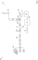
- FIG. 1 shows a flow chart of a wood material manufacturing device 10 according to the invention for producing wood material 11.
- the wood material manufacturing device 10 has a cooker 14 which receives wood chips 18 heated from a pre-cooker 16.
- the wood chips 18 were cleaned in the pre-cooker 16 so that the pre-cooker 16 has the function of a washing system.
- the wood material manufacturing device can have a separate washing system 24.
- a refiner 32 is arranged behind the cooker 14 in the wood material flow direction H, by means of which the wood chips 18 coming from the cooker 14 are shredded. Together with steam 26, a steam-fiber material mixture 38 is thus created.
- the steam-fiber material mixture 38 can be fed to a gluing device 40, the preferably designed as a blow line, but this is not necessary.
- the steam-fiber material mixture 38 can also be fed to a dryer 44, from which exhaust air 45 and dried wood material 11 leave, but the dryer is also not necessary. Exhaust air 45 that is created in the dryer 44.
- the particle load of the exhaust air 45 can be reduced by means of an optional wet electrostatic precipitator 47.
- the wood-based material 11 is used, for example, for the production of insulation material, medium-density fibreboards (MDF), lightweight medium-density fibreboards (LDF), high-density fibreboards (HDF), plant substrate for plant cultivation, for example potting soil, or packaging material.
- MDF medium-density fibreboards
- LDF lightweight medium-density fibreboards
- HDF high-density fibreboards
- plant substrate for plant cultivation for example potting soil, or packaging material.
- the exhaust air cleaner 52 is described below in connection with Figure 4 described in detail.
- the wood material manufacturing device 10 is part of a wood material panel manufacturing device 76, in the present case in the form of a wood fiber panel manufacturing device.
- the wood chips 18 can be produced from fresh wood 22, fresh wood chips 23 or recycled wood 25 by means of a shredder 20.
- the wood-based panel manufacturing device 76 has a sifter 78 which removes wood-based particles outside a predetermined target size interval.
- a fiber cake 48 is spread from the wood-based material 11 by means of a spreader 46 and pressed into the wood fiber panels 12 by means of a press 50, in particular a hot press.
- FIG. 2 shows a second wood material manufacturing device 10, which is part of a wood material panel manufacturing device 76 in the form of an OSB manufacturing device.
- the wood chips 18 are produced by means of the shredder 20, for example a chipper, and dried in the dryer 44.
- the resulting exhaust air 45 is cleaned by means of the exhaust air cleaner 52 described below and then passes into the chimney 67.
- the sifter 78 and the spreader 46 are arranged behind the dryer 44 in the direction of wood flow H.
- the sifter 78 classifies the particles of the wood material 11 into top layer particles and middle layer particles.
- the spreader 46 spreads a first top layer D1 made of top layer particles, a middle layer M made of middle layer particles arranged on the top layer D1 and a second top layer D2 made of top layer particles arranged on the middle layer M. These layers are pressed by the press 50 to form an OSB 80.
- FIG. 3 shows a third wood material manufacturing device 10, which is part of a wood material panel manufacturing device 76 in the form of a chipboard manufacturing device for producing a chipboard 82.
- the chips 18 produced by the shredder 20 are dried in the dryer 44 and the resulting exhaust air 45 is cleaned in the exhaust air cleaner 52 described below before it reaches the chimney 67.
- the classifier 78 classifies the particles of the wood material 11 into cover layer particles and middle layer particles.
- the spreader 46 spreads a fiber cake 48 consisting of a first cover layer D1 made of cover layer particles, a middle layer made of middle layer particles arranged on the first cover layer D1 and a second cover layer D2 made of cover layer particles arranged on the middle layer M.
- the fiber cake 48 is pressed into the chipboard 82 by means of the press 50.
- FIG 4 shows a further wood material manufacturing device 10 according to the invention and a wood material panel manufacturing device 76 according to the invention.
- the wood chips 18 produced by the shredder 20 are heated with steam 26 from a steam generator 28 in the pre-cooker and then cooked in the cooker 14. They are then shredded in the refiner 32, the steam-fiber material mixture 38 is glued in the gluing device 40 and then dried in the dryer 44.
- the exhaust air cleaner 52 is arranged behind the dryer 44 in the material flow direction M. This introduces an oxidizing agent 56 into the exhaust air 45 at an introduction point 54.
- the oxidizing agent is hydrogen peroxide H 2 O 2 .
- the exhaust air cleaner 52 comprises an oxidant source 58, which in the present case an oxidizing agent container 58 and a feeder 60 in the form of an oxidizing agent pump.
- the exhaust air cleaner 52 measures a first VOC concentration c VOC,1 of volatile organic components in the exhaust air 45 by means of a VOC concentration meter 62.
- an oxidizing agent volume flow Qse of oxidizing agent 56 is introduced, for example sprayed, into the exhaust air 45 by means of an introduction device 57 at the introduction point 54.
- the oxidizing agent 56 reacts with volatile organic components in the exhaust air 45.
- the exhaust air cleaner 52 can have a second VOC concentration meter 64, which is located behind the introduction point 54 in the exhaust gas flow direction D.
- the second VOC concentration meter measures a second VOC concentration c VOC,2 . In the present case, this is the TOC concentration of the total concentration of organic compounds. If the second VOC concentration c VOC,2 is above a predetermined maximum concentration c VOC,max , the oxidizing agent volume flow Q 56 is increased.
- the maximum concentration corresponds to a specified exhaust air limit concentration c VOC,BREV , which is a legal requirement, for example.
- the maximum concentration is smaller than the exhaust air limit concentration c VOC,BREV .
- c VOC,max f * c VOC,BREV with a safety factor fe [0.75, ...,1]. The smaller the safety factor, the lower the probability that the exhaust air limit concentration c VOC,BREV will be exceeded at any time, but the higher the consumption of oxidizing agent.
- the exhaust air cleaner 52 regulates the second VOC concentration c VOC,2 to a VOC target concentration c VOC,target by increasing or decreasing the oxidizing agent volume flow Q 56 .
- the exhaust air cleaner 52 it is possible for the exhaust air cleaner 52 to have an introduction device, for example a nozzle 66, for introducing oxidizing agent at a second introduction point 54.2 in the exhaust gas flow direction D behind the second VOC concentration meter 64.
- an introduction device for example a nozzle 66
- the oxidizing agent volume flow Q 56 is increased if the second VOC concentration c VOC,2 . is above the maximum concentration c VOC,max . It is possible, but not necessary, that the same oxidizing agent is introduced at both introduction points 54, 54.2. In particular, it is possible that 2 different oxidizing agents are used.
- the exhaust air cleaner 52 prefferably has only one VOC concentration meter 64, which is arranged behind the introduction point 54 in the steam flow direction D, wherein oxidizing agent is only introduced into the exhaust air 45 at this one introduction point 54.
- the introduction of the oxidizing agent produces purified exhaust air 45.2, which is released into the environment via a chimney 67.
- the exhaust air cleaner 52 can have a light source 74 by means of which the oxidizing agent 56 can be irradiated with UV light. In this way, hydroxyl radicals are formed, which particularly effectively destroy the volatile organic substances in the diverted steam 26.
- An exhaust air temperature T 45 is, for example, 45°C ⁇ 5°C.
- the oxidizing agent 56 in this case is a 5 percent (weight percent) hydrogen peroxide solution.
- One standard cubic meter is the amount of gas that occupies 1 cubic meter under standard conditions of 1013 hPa and 23°C.
- the wood material manufacturing device 10 can be part of a wood material panel manufacturing device 76, which comprises a spreader 46 for spreading glued wood material 11 on a conveyor belt so that a fiber cake 48 is formed.
- the fiber cake 48 is pressed into a wood fiber panel 12 by means of a press 50.
Landscapes
- Life Sciences & Earth Sciences (AREA)
- Engineering & Computer Science (AREA)
- Manufacturing & Machinery (AREA)
- Wood Science & Technology (AREA)
- Forests & Forestry (AREA)
- Dry Formation Of Fiberboard And The Like (AREA)
Abstract
Die Erfindung betrifft ein Verfahren zum Herstellen eines Holzwerkstoffs, bei dem Abluft (45) entsteht, die volatile organische Substanzen, insbesondere Terpene und/oder Aldehyde, enthält, und die in die Umgebung abgegeben wird, durch den Schritt Einbringen eines Oxidationsmittels (56) in die Abluft, sodass in der Abluft (45) enthaltene volatile organische Substanzen oxidiert werden und gereinigte Abluft (45.2) entsteht.
Description
- Die Erfindung betrifft ein Verfahren zum Herstellen eines Holzwerkstoffs, bei dem Abluft entsteht, die volatile organische Substanzen, insbesondere Terpene und/oder Aldehyde, enthält und die in die Umgebung abgegeben wird.
- Gemäß einem zweiten Aspekt betrifft die Erfindung eine Holzwerkstoff-Herstellvorrichtung zum Herstellen eines Holzwerkstoffs, mit (a) einem Zerkleinerer zum Zerkleinern von Holz und (b) einem Trockner zum Trocknen von zerkleinertem Holz, sodass Abluft entsteht, die volatile organische Substanzen, insbesondere Terpene und/oder Aldehyde, enthält,
- Holzwerkstoffe werden aus Holz hergestellt und dienen beispielsweise der Herstellung von Spanplatten, OSB-Platten, Holzfaserplatten oder von Dämmmaterial. Bei der Herstellung, insbesondere dem Trocknen, von zerkleinertem Holz, insbesondere Holzspänen oder Holzfasern, werden volatile organische Substanzen (volatile organic compounds, VOC) frei, die in die Abluft übergehen. Derartige VOCs belasten die Umwelt, es existieren daher Grenzwerte an VOCs in der Abluft, die nicht überschritten werden dürfen.
- Ist der als Werkstoff ein Holzfaserstoff, so erfordert die Herstellung dieses Holzwerkstoffs große Mengen an Dampf, die teilweise abgezweigt und zum Erwärmen oder zum Kochen der Holzhackschnitzel verwendet wird, wie aus der
US 4 925 527 bekannt ist. Um zu verhindern, dass sich im Holz befindliche volatile organische Substanzen im Holzwerkstoffe anreichern, wird ein Teil des Dampfs kondensiert, die terpenreichen Anteile abgeschieden und die beim Kondensieren frei werdende Wärme zum Verdampfen von Wasser genutzt. Dieser Prozess ist aufwendig und wenig energieeffizient. - Der Erfindung liegt die Aufgabe zugrunde, VOCs in der Abluft zu vermindern.
- Die Erfindung löst das Problem durch ein gattungsgemäßes Verfahren mit dem Schritt des Einbringens eines Oxidationsmittels in die Abluft, sodass in der Abluft enthaltene volatile organische Substanzen oxidiert werden und gereinigte Abluft entsteht.
- Die Erfindung löst das Problem zudem durch eine gattungsgemäße Holzwerkstoff-Herstellvorrichtung, die einen Abluftreiniger aufweist, der ausgebildet ist zum Einbringen eines Oxidationsmittels in die Abluft, sodass in der Abluft enthaltene volatile organische Substanzen oxidiert werden und gereinigte Abluft entsteht.
- Vorteilhaft an der Erfindung ist, dass vorgegebene Grenzwerte für die Abgabe an volatilen organischen Substanzen in die Umgebung mit vergleichsweise geringem technischem Aufwand innerhalb vorgegebener Grenzwerte gehalten werden kann.
- Im Rahmen der vorliegenden Beschreibung wird unter einem Abluftreiniger eine Vorrichtung verstanden, mittels der eine VOC-Konzentration, insbesondere an Terpenen und/oder Aldehyden, durch chemische Reaktion der volatilen organischen Verbindungen mit ein Oxidationsmittel, um zumindest 50 %, insbesondere zumindest 70%, reduziert werden kann. Es handelt sich dabei um die maximal mögliche Reduzierung an volatilen organischen Substanzen.
- Unter Abluft wird ein Gemisch aus Luft, gegebenenfalls Partikeln, gegebenenfalls gasförmigem Wasser und gegebenenfalls Flüssigkeitströpfchen, insbesondere Wassertropfen, verstanden.
- Vorzugsweise ist das Oxidationsmittel ein Mittel zur flammenlosen Oxidation. Gemäß einer Ausführungsform ist das Oxidationsmittel sauerstoffhaltig. Günstig ist es, wenn das Oxidationsmittel bei Reaktion mit Terpenen und/oder Aldehyden elementaren Sauerstoff abgibt. Beispielsweise handelt es sich beim Oxidationsmittel um Wasserstoffperoxid oder Ozon. Wenn von Wasserstoffperoxid gesprochen wird, wird darunter auch eine wässrige Lösung von Wasserstoffperoxid verstanden. Das Wasserstoffperoxid kann ein Fe(II)-Salz, Ammoniumpersulfat, Cytochrom P450, Monooxygenasen oder Ammoniumperoxid enthalten. Insbesondere ist das Oxidationsmittel kein molekularer Sauerstoff oder Luft.
- Gemäß einer bevorzugten Ausführungsform umfasst das Verfahren die Schritte (a) Erwärmen von Holzhackschnitzeln in einem Vorkocher mittels Wasser oder Dampf, (b) danach Kochen der Holzhackschnitzel mittels Dampf in einem Kocher, und danach (c) Zerfasern der Holzhackschnitzel in einem Refiner, sodass Fasermaterial und Abluft entsteht. In diesem Fall enthält die Abluft Dampf oder kondensierten Dampf, also Luft mit Flüssigkeitstropfen.
- Unter dem Kochen der Holzhackschnitzel wird insbesondere verstanden, dass die Hackschnitzel mit Wasser und/oder Dampf erhitzt werden. Die Holzhackschnitzel werden vorzugsweise zunächst in den Vorkocher, danach in den Kocher eingebracht.
- Erfindungsgemäß ist zudem ein Verfahren zum Herstellen einer Holzfaserplatte, in dessen Rahmen das oben genannte Verfahren durchgeführt wird. Unter einer Holzfaserplatte wird insbesondere eine LDF, MDF oder HDF verstanden. Das Fasermaterial sind Holzfasern.
- Erfindungsgemäße ist auch ein Verfahren zum Herstellen von Dämmmaterial oder Pflanzen-Substrat für den Pflanzenbau, in dessen Rahmen das oben genannte Verfahren durchgeführt wird.
- Erfindungsgemäß ist zudem ein Verfahren zum Herstellen einer Spanplatte, in dessen Rahmen das oben genannte Verfahren durchgeführt wird. In diesem Fall umfasst das Verfahren vorzugsweise die Schritte (a) Zerspanung von Rundholz, Holzresten und/oder Altholz, sodass Holzspäne entstehen, (b) Trocknen der Holzspäne, (c) Beleimen der Holzspäne, (d) Streuen der beleimten Holzspäne und Formgebung zu einer Spanmatte und (e) Verpressen der Spanmatte zu einer Spanplatte. Es ist möglich, dass die Holzspäne in mehreren Lagen gestreut werden.
- Ebenfalls erfindungsgemäß ist ein Verfahren zum Herstellen einer OSB-Platte, in dessen Rahmen das oben genannte Verfahren durchgeführt wird. In diesem Fall umfasst das Verfahren vorzugsweise die Schritte (a) Zerspanung von Rundholz, Holzresten und/oder Altholz, sodass Grobspäne entstehen, (b) Trocknen der Grobspäne, (c) Beleimen der Grobspäne, (d) Streuen der beleimten Grobspäne zu einer Spanmatte und (e) Verpressen der Spanmatte zu einer OSB-Platte.
- Es ist möglich, dass die Grobspäne in mehreren Lagen gestreut werden. Vorzugsweise unterscheiden sich die Vorzugsorientierungen der Grobspäne zumindest zweier benachbarter Lagen. Beispielsweise verläuft die Vorzugsorientierung der zweiten Lage quer zur Vorzugsorientierung der ersten Lage, auf die die zweite Lage aufgebracht ist. Verläuft beispielsweise die Vorzugsorientierung der ersten Lage entlang der Förderrichtung, in die sich die Spanmatte bewegt, so verläuft vorzugsweise die Vorzugsorientierung der zweiten Lage quer zur Fahrtrichtung. Die Vorzugsorientierung ist diejenige Richtung, in die sich die meisten Längsachsen der (länglichen) Grobspäne erstrecken.
- Günstig ist es, wenn die VOC-Konzentration cVOC,1, also die Konzentration an volatilen organischen Substanzen, insbesondere Terpene und/oder Aldehyde, in der Abluft, kontinuierlich gemessen wird. Die VOC-Konzentration cVOC,1 wird beispielsweise in Masse pro Abluftvolumen oder in Masseanteil an der Abluft angegeben.
- Unter der VOC-Konzentration wird eine Konzentration verstanden, anhand der auf die Konzentration an volatilen organischen Bestandteilen geschlossen werden kann. Insbesondere ist auch die TOC-Konzentration aller organischen Kohlenstoff-Verbindungen eine VOC-Konzentration, wenn es um das Einhalten einer Obergrenze geht. Wenn im Folgenden von der VOC-Konzentration gesprochen wird, könnte verallgemeinernd stets auch von der TOC-Konzentration gesprochen werden (TOC = total organic carbon, gesamter organischer Kohlenstoff).
- Vorzugsweise wird das Einbringen des Oxidationsmittels in die Abluft anhand der VOC-Konzentration gesteuert. In anderen Worten wird insbesondere die Menge an Oxidationsmittel, nämlich der Oxidationsmittelstrom, die in die Abluft eingebracht wird, erhöht, wenn die VOC-Konzentration steigt. Zusätzlich kann die Menge an Oxidationsmittel, die in die Abluft eingebracht wird, gesenkt werden, wenn die VOC-Konzentration sinkt. Auf diese Weise wird einerseits stets genug Oxidationsmittel in die Abluft eingebracht und andererseits der Verbrauch an Oxidationsmittel minimiert. Günstig ist es, wenn diese VOC-Konzentration in Abgasflussrichtung vor einer Einbringstelle gemessen wird, an der das Oxidationsmittel in die Abluft eingebracht wird.
- Vorzugsweise umfasst das Verfahren die Schritte (a) Vergleichen der VOC-Konzentration cVOC,1 mit einer Grenzwert-Konzentration cVOC,G und (b) wenn die VOC-Konzentration cVOC,1 die Grenzwert-Konzentration cVOC,G unterschreitet, Einbringen eines Leerlaufstroms an Oxidationsmittel, insbesondere von keinem Oxidationsmittel. Auf diese Weise wird Oxidationsmittel eingespart, da es nicht notwendig ist, um die Grenzwert-Konzentration cVOC,G in der Abluft zu unterschreiten. Es ist aber möglich, dass ein Leerlaufstrom an Oxidationsmittel in die Abluft eingebracht wird, beispielsweise um den Oxidationsmittelstrom schnell erhöhen zu können, wenn dies notwendig wird. Der Leerlaufstrom ist ein Volumenstrom an Oxidationsmittel, der kleiner ist als der Oxidationsmittelstrom, der notwendig ist, wenn die Menge an VOC reduziert werden soll. Beispielsweise beträgt der Leerlaufstrom höchstens ein Fünftel, insbesondere ein Zehntel, des Stroms, der eingebracht wird, wenn die Grenze-Konzentration überschritten wird.
- Wenn die VOC-Konzentration cVOC,1 die Grenzwert-Konzentration (cVOC,G) nicht unterschreitet, wird vorzugsweise ein Oxidationsmittelstrom in die Abluft eingebracht, wobei der Oxidationsmittelstrom so gewählt ist, dass eine Abgabe-VOC-Konzentration (cVOC,A) in der Abluft, der in die Umgebung abgegeben wird, unterhalb einer vorgegebenen Abluft-Grenzwert-Konzentration cVOC,BREV liegt. Bei der Abluft-Grenzwert-Konzentration handelt es sich beispielsweise um eine gesetzliche Vorgabe. Beispielsweise kann cVOC,BREV = 400 µg/m3 gelten. Das Volumen wird vorzugsweise in Norm-Kubikmetern gemessen, also das Volumen des Gases unter Standardbedingungen (23 °C, 1013 hPa).
- Gemäß einer Ausführungsform wird kontinuierlich eine zweite VOC-Konzentration an volatilen organischen Substanzen, insbesondere Terpenen und/oder Aldehyden, in der Abluft gemessen. Das erfolgt insbesondere in Abluftströmungsrichtung hinter einer Einbringstelle, an der Oxidationsmittel in die Abluft eingebracht wird.
- Vorzugsweise wird das Einbringen des Oxidationsmittels in die Abluft auch oder ausschließlich anhand der zweiten VOC-Konzentration gesteuert oder geregelt.
- Steigt beispielsweise die zweite VOC-Konzentration über die Abluft-Grenzwert-Konzentration cVOC,BREV, so wird gemäß einer bevorzugten Ausführungsform die pro Zeiteinheit eingebrachte Menge an Oxidationsmittel (Oxidationsmittelfluss) erhöht. Das erfolgt insbesondere auch dann, wenn die erste VOC-Konzentration sich nicht ändert.
- Sinkt die zweite VOC-Konzentration unter eine vorgegebene Minimal-Konzentration, so wird gemäß einer bevorzugten Ausführungsform der Oxidationsmittelfluss vermindert. Das erfolgt insbesondere auch dann, wenn die erste VOC-Konzentration sich nicht ändert.
- Möglich ist, dass lediglich die zweite VOC-Konzentration gemessen wird, die dann noch nicht als zweite VOC-Konzentration bezeichnet werden muss, sondern allgemein VOC-Konzentration genannt werden kann.
- Gemäß einer Ausführungsform umfasst das Verfahren den Schritt des Bestrahlens des Oxidationsmittels mit UV-Licht. Dadurch wird bei einem geeigneten Oxidationsmittel beispielsweise erreicht, dass das Oxidationsmittel Radikale bildet. Handelt es sich bei dem Oxidationsmittel beispielsweise um Wasserstoffperoxid, bilden sich Hydroxylradikale. Diese reagieren besonders schnell mit VOCs.
- Vorzugsweise erfolgt das Bestrahlen des Oxidationsmittels mit UV-Licht unmittelbar vor dem Einbringen in die Abluft. Insbesondere beträgt ein Abstand zwischen der Stelle, an der das Oxidationsmittel mit UV-Licht bestrahlt wird und der Stelle, an der das Oxidationsmittel erstmals in Kontakt mit dem abgezweigten Dampf kommt, höchstens 10 m, insbesondere höchstens 5 m.
- Vorzugsweise hat die Abluft beim Einbringen des Oxidationsmittels eine Ablufttemperatur von zumindest 40°C. Bei höheren Temperaturen regiert das Oxidationsmittel schneller mit den volatilen organischen Substanzen, sodass geringere Konzentrationen an volatilen organischen Substanzen im gereinigten Dampf erreichbar sind.
- Hohe Ablufttemperaturen bedeuten jedoch einen Energieverlust, sodass es günstig ist, wenn die Ablufttemperatur höchstens 80°C beträgt.
- Vorzugsweise hat der Abluft einen Druck von zumindest 1,2 bar und/oder höchstens 5 bar.
- Vorzugsweise umfasst das Verfahren den Schritt des Trocknens des Holzwerkstoffs, insbesondere der Holzspäne, der Grobspäne oder der Holzfasern. Bei dem Trocknen entstehende Abluft wird vorzugsweise wie oben geschildert durch Einbringen des Oxidationsmittels gereinigt, bevor die Abluft in die Umgebung abgegeben wird.
- Wenn es sich beim Holzwerkstoff um Holzspäne, Grobspäne oder um Holzfasern handelt, umfasst das Verfahren vorzugsweise den Schritt des Beleimens, insbesondere mittels einer Blow-Line, des Holzwerkstoffs. Gemäß einer Ausführungsform ist vorgesehen, dass das beleimte Fasermaterial getrocknet wird.
- Günstig ist es, wenn das Verfahren die Schritte des Streuens des, insbesondere getrockneten und/oder beleimten, Fasermaterials zu einem Faserkuchen und des Verpressens des Faserkuchens zu einer Holzwerkstoffplatte, insbesondere einer Spanplatte, einer MDF-, einer MDF-oder einer HDF-Platte oder einer OSB-Platte aufweist. Das Verpressen erfolgt beispielsweise mittels einer Bandpresse.
- Eine erfindungsgemäße Holzwerkstoff-Herstellvorrichtung besitzt vorzugsweise einen Kamin, der mit dem Abluftreiniger verbunden ist zum Abgeben der gereinigten Abluft in die Umgebung.
- Der Abluftreiniger kann einen Oxidationsmitteltank, der mit Oxidationsmittel, beispielsweise Wasserstoffperoxid, gefüllt ist, aufweisen. Vorzugsweise besitzt der Abluftreiniger zudem eine Pumpe zum Fördern des Oxidationsmittels zur Einbringvorrichtung. Alternativ oder zusätzlich kann der Abluftreiniger einen Oxidationsmittelerzeuger aufweisen, mittels dem Oxidationsmittel herstellbar ist. Beispielsweise kann der Oxidationsmittelerzeuger ein Ozongenerator sein. Alternativ oder zusätzlich kann der Abluftreiniger einen Oxidationsmittelbehälter aufweisen, in dem Oxidationsmittel gespeichert werden kann. Beispielsweise ist der Oxidationsmittelbehälter mit Wasserstoffperoxid gefüllt.
- Günstig ist es, wenn die Holzfaserplatten-Herstellvorrichtung einen VOC-Konzentrationsmesser zum Messen einer (ersten) VOC-Konzentration an volatilen organischen Substanzen, insbesondere Terpenen oder Aldehyden, und/oder der Gesamtkonzentration an organischen Kohlenstoffverbindungen in der Abluft in Abgasflussrichtung vor einer Einbringstelle, an der das Oxidationsmittel in die Abluft eingebracht wird, aufweist.
- Der Zudosierer ist vorzugsweise ausgebildet zum automatischen Einbringen des Oxidationsmittels in die Abluft anhand der gemessenen VOC-Konzentration. In anderen Worten steuert oder regelt der Zudosierer den Oxidationsmittelstrom. Beispielsweise enthält der Zudosierer dazu eine regelbare Pumpe und/oder ein ansteuerbares Ventil.
- Der VOC-Konzentrationsmesser umfasst beispielsweise einen Gaschromatographen mit einem Flammenionisationsdetektor. Der VOC-Konzentrationsmesser ist vorzugsweise ausgebildet zum automatischen Messen der VOC-Konzentration in regelmäßigen Abständen, beispielsweise häufiger als einmal pro Stunde, insbesondere häufiger als einmal pro halber Stunde, besonders bevorzugt häufiger als einmal pro 10 Minuten.
- In einer bevorzugten Ausführungsform ist der Zudosierer ausgebildet zum Erfassen der VOC-Konzentration vom VOC-Konzentrationsmesser und zum automatischen Einbringen des Oxidationsmittels in die Abluft anhand der VOC-Konzentration und des Abluftstroms. In anderen Worten wird ein Oxidationsmittelvolumenstrom an Oxidationsmittel, der pro Zeiteinheit in die Abluft eingebracht wird, insbesondere anhand der VOC-Konzentration und gegebenenfalls des Abluftstroms berechnet und dann das Oxidationsmittel entsprechend eingebracht.
- Die Holzwerkstoff-Herstellvorrichtung besitzt vorzugsweise eine erste Einbringvorrichtung zum Einbringen des Oxidationsmittels in die Abluft an einer ersten Einbringstelle.
- Besonders günstig ist es, wenn der Abluftreiniger ausgebildet ist zum Regeln der VOC-Konzentration auf eine vorgegebene VOC-Soll-Konzentration. Bei Abweichung der gemessenen VOC-Konzentration von der VOC-Soll-Konzentration wird der Oxidationsmittelvolumenstrom so angepasst, dass sich die gemessene VOC-Konzentration der VOC-Soll-Konzentration annähert. Liegt die gemessene VOC-Konzentration oberhalb der VOC-Soll-Konzentration, wird der Oxidationsmittelvolumenstrom erhöht. Liegt die gemessene VOC-Konzentration unterhalb der VOC-Soll-Konzentration, wird der Oxidationsmittelvolumenstrom verringert.
- Gemäß einer bevorzugten Ausführungsform besitzt die Holzwerkstoff-Herstellvorrichtung einen zweiten VOC-Konzentrationsmesser zum Messen einer zweiten VOC-Konzentration (oder einer zweiten TOC-Konzentration) in der Abluft in Abgasflussrichtung hinter der Einbringstelle. Der Zudosierer ist vorzugsweise ausgebildet zum automatischen Einbringen des Oxidationsmittels in die Abluft anhand der ersten VOC-Konzentration und der zweiten VOC-Konzentration, sowie gegebenenfalls des Abluftstroms. In anderen Worten ist der Zudosierer ausgebildet zum Steuern oder Regeln des Oxidationsmittelvolumenstroms anhand der ersten und der zweiten VOC-Konzentration. Es ist möglich, dass die Holzwerkstoff-Herstellvorrichtung einen VOC-Konzentrationsmesser in Abgasflussrichtung hinter der Einbringstelle aufweist. In diesem Fall kann der zweite VOC-Konzentrationsmesser lediglich VOC-Konzentrationsmesser genannt werden.
- Die Holzwerkstoff-Herstellvorrichtung besitzt vorzugsweise eine zweite Einbringvorrichtung zum Einbringen des Oxidationsmittels in die Abluft an einer zweiten Einbringstelle, die in Abgasflussrichtung hinter der ersten Einbringstelle liegt. Vorzugsweise liegt die zweite Einbringstelle hinter dem zweiten VOC-Konzentrationsmesser. Günstig ist es, wenn der Abluftreiniger ausgebildet ist zum Steuern eines zweiten Oxidationsmittelvolumenstroms an Oxidationsmittel, der an der zweiten Einbringstelle eingebracht wird, in Abhängigkeit von der zweiten VOC-Konzentration.
- Besonders günstig ist es, wenn der Abluftreiniger ausgebildet ist zum Regeln der zweiten VOC-Konzentration auf eine vorgegebene zweite VOC-Soll-Konzentration. Bei Abweichung der gemessenen zweiten VOC-Konzentration von der zweiten VOC-Soll-Konzentration wird der erste und/oder zweite Oxidationsmittelvolumenstrom so angepasst, dass sich die gemessene zweite VOC-Konzentration der zweiten VOC-Soll-Konzentration annähert. Liegt die gemessene zweite VOC-Konzentration oberhalb der zweiten VOC-Soll-Konzentration, werden der erste und/oder der zweite Oxidationsmittelvolumenstrom erhöht. Liegt die gemessene zweite VOC-Konzentration unterhalb der zweiten VOC-Soll-Konzentration, werden der erste und/oder der zweite Oxidationsmittelvolumenstrom verringert. Beispielsweise liegt die VOC-Soll-Konzentration unterhalb der Abluft-Grenzwert-Konzentration cVOC,BREV.
- Vorzugsweise weist die Holzwerkstoff-Herstellvorrichtung eine Beleimvorrichtung zum Beleimen des Fasermaterials auf. Unter einer Beleimvorrichtung wird eine Vorrichtung verstanden, mittels der das Fasermaterial beleimt werden kann. Die Beleimvorrichtung kann auch als Beleimer bezeichnet werden.
- Erfindungsgemäß ist auch eine Holzwerkstoffplatten-Herstellvorrichtung zum Herstellen einer Holzwerkstoffplatte, die eine erfindungsgemäße Holzwerkstoff-Herstellvorrichung aufweist. Die Holzwerkstoffplatten-Herstellvorrichtung ist beispielsweise eine Holzfaserplatten-Herstellvorrichtung zum Herstellen von leichten, mitteldichten Faserplatten (LDF), mitteldichten Faserplatten (MDF) und/oder hochdichten Faserplatten (HDF), die die ist erfindungsgemäße Holzwerkstoff-Herstellvorrichtung aufweist. Alternativ ist die Holzwerkstoffplatten-Herstellvorrichtung eine Spanplatten-Herstellvorrichtung zum Herstellen von Spanplatten. Wiederum alternativ ist die Holzwerkstoffplatten-Herstellvorrichtung eine OSB-Herstellvorrichtung zum Herstellen von Grobspanplatten.
- Die Holzfaserplatten-Herstellvorrichtung besitzt vorzugsweise (a) einen Kocher zum Kochen von Holzhackschnitzeln mittels Dampf, sodass gekochte Holzhackschnitzel entstehen, (b) einen Refiner, der in Holzmaterialflussrichtung hinter dem Kocher angeordnet ist, zum Zerfasern der gekochten Holzhackschnitzel, sodass Fasermaterial entsteht und optional (c) eine in Holzmaterialflussrichtung hinter dem Refiner angeordneten Beleimvorrichtung, insbesondere einer Blow-Line, zum Beleimen des Fasermaterials, sodass beleimtes Fasermaterial entsteht.
- Die Holzfaserplatten-Herstellvorrichtung besitzt vorzugsweise einen Streuer zum Streuen von getrocknetem Fasermaterial zu einem Faserkuchen. Günstig ist es, wenn die Holzfaserplatten-Herstellvorrichtung eine Presse, insbesondere eine Bandpresse, zum Verpressen des Faserkuchens zur Holzfaserplatten aufweist.
- Unter einer Holzfaserplatte wird eine Platte verstanden, die unter Verwendung von Holz hergestellt wird. Vorzugsweise hat die Holzfaserplatte eine Dicke zwischen 2 mm und 60 mm. Vorzugsweise beträgt eine Dichte der Holzfaserplatte zwischen 600 kg pro Kubikmeter und 1000 kg pro Kubikmeter.
- Unter Dämmmaterial wird insbesondere plattenförmiger Dämmstoff verstanden. Dieser kann eine Dichte zwischen 50 und 400 kg pro Kubikmeter haben. Eine Dicke des plattenförmigen Dämmstoffs beträgt vorzugsweise 2 bis 800 mm.
- Eine Spanplatten-Herstellvorrichtung besitzt vorzugsweise einen Streuer zum Streuen eines Faserkuchens aus beleimtem Holzwerkstoff in Form von Holzspänen zu einem Faserkuchen und eine Heißpresse zum Verpressen des Faserkuchens zur Spanplatte.
- Eine OSB-Herstellvorrichtung oder eine Spanplatten-Herstellvorrichtung besitzt vorzugsweise einen Streuer, der ausgebildet ist zum Streuen einer ersten Deckschicht, einer Mittelschicht auf die erste Deckschicht und einer zweiten Deckschicht auf die Mittelschicht. Günstig ist es, wenn der Median der Größenverteilung der Späne der Mittelschicht kleiner, insbesondere um zumindest 15% kleiner, ist als der Median der Größenverteilung der Späne der ersten Deckschicht und/oder der zweiten Deckschicht.
- Günstig ist es, wenn in Holzmaterialflussrichtung vor dem Streuer einen Sichter angeordnet ist, mittels dem Holzwerkstoffpartikel, deren Größe außerhalb eines vorgegebenen Soll-Größenintervalls liegt, entfernt werden.
- Im Folgenden wird die Erfindung anhand der beigefügten Zeichnungen näher erläutert. Dabei zeigt
- Figur 1
- ein Flussdiagramm einer erfindungsgemäßen Holzwerkstoff-Herstellvorrichtung als Teil einer erfindungsgemäßen Holzfaserplatten-Herstellvorrichtung zum Durchführen eines erfindungsgemäßen Verfahrens gemäß einer ersten Ausführungsform,
- Figur 2
- ein Flussdiagramm einer erfindungsgemäßen Holzwerkstoff-Herstellvorrichtung als Teil einer erfindungsgemäßen OSB-Herstellvorrichtung zum Durchführen eines erfindungsgemäßen Verfahrens gemäß einer zweiten Ausführungsform,
- Figur 3
- ein Flussdiagramm einer erfindungsgemäßen Holzwerkstoff-Herstellvorrichtung als Teil einer erfindungsgemäßen Spanplatten-Herstellvorrichtung zum Durchführen eines erfindungsgemäßen Verfahrens gemäß einer dritten Ausführungsform und
- Figur 4
- ein Flussdiagramm einer erfindungsgemäßen Holzwerkstoff-Herstellvorrichtung als Teil einer erfindungsgemäßen Holzfaserplatten-Herstellvorrichtung zum Durchführen eines erfindungsgemäßen Verfahrens gemäß einer zweiten Ausführungsform.
-
Figur 1 zeigt ein Flussdiagramm einer erfindungsgemäßen Holzwerkstoff-Herstellvorrichtung 10 zum Herstellen von Holzwerkstoff 11. Die Holzwerkstoff-Herstellvorrichtung 10 besitzt einen Kocher 14, der von einem Vorkocher 16 erwärmte Holzhackschnitzel 18 erhält. Die Holzhackschnitzel 18 wurden im Vorkocher 16 gereinigt, sodass der Vorkocher 16 die Funktion einer Waschanlage hat. Alternativ kann die Holzwerkstoff-Herstellvorrichtung eine gesonderte Waschanlage 24 aufweisen. - In Holzmaterialflussrichtung H hinter dem Kocher 14 ist eine Refiner 32 angeordnet, mittels dem die aus dem Kocher 14 kommenden Holzhackschnitzel 18 zerfasert werden. Zusammen mit Dampf 26 entsteht so ein Dampf-Fasermaterial-Gemisch 38.
- Das Dampf-Fasermaterial-Gemisch 38 kann einer Beleimvorrichtung 40, der vorzugsweise als Blow-Line ausgeführt ist, zugeführt werden, das ist aber nicht notwendig. Das Dampf-Fasermaterial-Gemisch 38 kann zudem einem Trockner 44 zugeleitet, den Abluft 45 und getrockneter Holzwerkstoff 11 verlassen, auch der Trockner ist aber nicht notwendig. Abluft 45, die im Trockner 44 entsteht. Die Abluft 45 kann mittels eines optionalen Nasselektrofilters 47 in seiner Partikellast reduziert werden.
- Der Holzwerkstoff 11 wird beispielsweise zur Herstellung von Dämmmaterial, von mitteldichten Holzfaserplatten (MDF), leichten mitteldichten Holzfaserplatten (LDF), hochdichten Holzfaserplatten (HDF), Pflanzen-Substrat für den Pflanzenbau, beispielsweise Blumenerde, oder Verpackungsmaterial verwendet.
- Ein in Abgasflussrichtung D hinter dem Trockner 44 und gegebenenfalls dem Nasselektrofilter 47 angeordneter Abluftreiniger 52 reduziert den Gehalt an VOC in der Abluft 45, bevor diese in einen Kamin 67 zur Abgabe an die Umgebung eingeleitet wird. Der Abluftreiniger 52 wird weiter unten im Zusammenhang mit
Figur 4 detailliert beschrieben. - Die Holzwerkstoff-Herstellvorrichtung 10 ist Teil einer Holzwerkstoffplatten-Herstellvorrichtung 76, im vorliegenden Fall in Form einer Holzfaserplatten-Herstellvorrichtung. Die Hackschnitzel 18 können aus Frischholz 22, frischen Holzhackschnitzeln 23 oder Recyclingholz 25 mittels eines Zerkleinerers 20 hergestellt werden.
- Die Holzwerkstoffplatten-Herstellvorrichtung 76 weist einen Sichter 78 auf, der Holzwerkstoffpartikeln außerhalb eines vorgegebenen Soll-Größtenintervalls entfernt. Mittels eines Streuers 46 wird ein Faserkuchen 48 aus dem Holzwerkstoff 11 gestreut und mittels einer Presse 50, insbesondere einer Heißpresse, zur Holzfaserplatten 12 verpresst.
-
Figur 2 zeigt eine zweite Holzwerkstoff-Herstellvorrichtung 10, die Teil einer Holzwerkstoffplatten-Herstellvorrichtung 76 in Form einer OSB-Herstellvorrichtung ist. Mittels des Zerkleinerers 20, beispielsweise eines Hackers, werden die Hackschnitzel 18 hergestellt und im Trockner 44 getrocknet. Die dabei entstehende Abluft 45 wird mittels des weiter unten beschriebenen Abluftreinigers 52 gereinigt und gelangt danach in den Kamin 67. - In Holzstromrichtung H hinter dem Trockner 44 sind der Sichter 78 und der Streuer 46 angeordnet. Der Sichter 78 klassiert die Partikel des Holzwerkstoffs 11 in Deckschicht-Partikel und Mittelschicht-Partikel. Der Streuer 46 gestreut eine erste Deckschicht D1 aus Deckschicht-Partikeln, eine auf der Deckschicht D1 angeordnete Mittelschicht M aus Mittelschicht-Partikeln und eine auf der Mittelschicht M angeordnete zweite Deckschicht D2 aus Deckschicht-Partikeln. Diese Schichten werden von der Presse 50 zu einer OSB 80 verpresst.
-
Figur 3 zeigt eine dritte Holzwerkstoff-Herstellvorrichtung 10, die Teil einer Holzwerkstoffplatten-Herstellvorrichtung 76 in Form einer Spanplatten-Herstellvorrichtung zum Herstellen einer Spanplatte 82. Die vom Zerkleinerer 20 hergestellten Schnitzel 18 werden im Trockner 44 getrocknet und die entstehende Abluft 45 im Leiter unten beschriebenen Abluftreiniger 52 gereinigt, bevor sie in den Kamin 67 gelangt. - In Holzstromrichtung H hinter dem Trockner 44 klassiert der Sichter 78 die Partikel des Holzwerkstoffs 11 in Deckschicht-Partikel und Mittelschicht-Partikel. Der Streuer 46 streut einen Faserkuchen 48, aus einer ersten Deckschicht D1 aus Deckschicht-Partikeln, einer auf der ersten Deckschicht D1 angeordneten Mittelschicht aus Mittelschicht-Partikeln und einer zweiten Deckschicht D2, die auf der Mittelschicht M angeordnet ist, aus Deckschicht-Partikeln. Der Faserkuchen 48 wird mittels der Presse 50 zur Spanplatte 82 verpresst.
-
Figur 4 zeigt eine weitere erfindungsgemäße Holzwerkstoff-Herstellvorrichtung 10 und eine erfindungsgemäße Holzwerkstoffplatten-Herstellvorrichtung 76. Die vom Zerkleinerer 20 hergestellten Hackschnitzel 18 werden mit Dampf 26 eines Dampferzeugers 28 im Vorkocher erhitzt und danach im Kocher 14 gekocht. Danach werden sie im Refiner 32 zerfasert, das Dampf-Fasermaterial-Gemisch 38 in der Beleimvorrichtung 40 beleimt und danach im Trockner 44 getrocknet. In Materialflussrichtung M hinter dem Trockner 44 ist der Abluftreiniger 52 angeordnet. Dieser bringt an einer Einbringstelle 54 ein Oxidationsmittel 56 in die Abluft 45 ein. Im vorliegenden Fall ist das Oxidationsmittel Wasserstoffperoxid H2O2. - Der Abluftreiniger 52 umfasst eine Oxidationsmittelquelle 58, die im vorliegenden Fall einen Oxidationsmittelbehälter 58 und einen Zudosierer 60 in Form einer Oxidationsmittelpumpe besitzt. Mittels eines VOC-Konzentrationsmessers 62 misst der Abluftreiniger 52 eine erste VOC-Konzentration cVOC,1 an volatilen organischen Komponenten in der Abluft 45. In Abhängigkeit von der VOC-Konzentration wird ein Oxidationsmittelvolumenstrom Qse an Oxidationsmittel 56 mittels einer Einbringvorrichtung 57 an der Einbringstelle 54 in die Abluft 45 eingebracht, beispielsweise eingedüst. Das Oxidationsmittel 56 reagiert mit volatilen organischen Komponenten in der Abluft 45.
- Der Abluftreiniger 52 kann einen zweiten VOC-Konzentrationsmesser 64 aufweisen, der in Abgasflussrichtung D hinter der Einbringstelle 54 liegt. Der zweite VOC-Konzentrationsmesser misst eine zweite VOC-Konzentration cVOC,2. Im vorliegenden Fall handelt es sich um die TOC-Konzentration der Gesamtkonzentration organischer Verbindungen. Liegt die zweite VOC-Konzentration cVOC,2 oberhalb einer vorgegebene Maximal-Konzentration cVOC,max, so wird der Oxidationsmittelvolumenstrom Q56 erhöht.
- Beispielsweise entspricht die Maximal-Konzentration einer vorgegebenen Abluft-Grenzwert-Konzentration cVOC,BREV, die beispielsweise eine gesetzliche Vorgabe ist. Es ist aber auch möglich, dass die Maximal-Konzentration kleiner ist als die Abluft-Grenzwert-Konzentration cVOC,BREV. So wird gewährleistet, dass die Abluft-Grenzwert-Konzentration cVOC,BREV sicher nicht überschritten wird. Beispielsweise gilt cVOC,max = f* cVOC,BREV mit einem Sicherheitsfaktor f e [0,75, ...,1]. Je kleiner der Sicherheitsfaktor, desto geringer ist die Wahrscheinlichkeit, dass die Abluft-Grenzwert-Konzentration cVOC,BREV zu irgendeinem Zeitpunkt überschritten wird, desto höher ist jedoch der Verbrauch an Oxidationsmittel.
- Der Abluftreiniger 52 regelt durch Erhöhen oder Vermindern des Oxidationsmittelvolumenstroms Q56 die zweite VOC-Konzentration cVOC,2 auf eine VOC-Soll-Konzentration cVOC,soll.
- Alternativ ist es möglich, dass der Abluftreiniger 52 in Abgasflussrichtung D hinter dem zweiten VOC-Konzentrationsmesser 64 eine Einbringvorrichtung, beispielsweise eine Düse 66, zum Einbringen von Oxidationsmittel an einer zweiten Einbringstelle 54.2 aufweist. Alternativ ist es möglich, dass der Oxidationsmittelvolumenstrom Q56 erhöht wird, wenn die zweite VOC-Konzentration cVOC,2. oberhalb der Maximal-Konzentration cVOC,max liegt. Es ist möglich, nicht aber notwendig, dass an beiden Einbringstellen 54, 54.2 das gleiche Oxidationsmittel eingebracht wird. Insbesondere ist es möglich, dass 2 unterschiedliche Oxidationsmittel verwendet werden.
- Es ist auch möglich, dass der Abluftreiniger 52 nur einen VOC-Konzentrationsmesser 64 aufweist, der in Dampfstromrichtung D hinter der Einbringstelle 54 angeordnet ist, wobei Oxidationsmittel nur an dieser einen Einbringstelle 54 in die Abluft 45 eingebracht wird.
- Durch das Einbringen des Oxidationsmittels entsteht gereinigte Abluft 45.2, die mittels eines Kamins 67 in die Umgebung abgegeben wird.
- Der Abluftreiniger 52 kann eine Lichtquelle 74 aufweisen, mittels der das Oxidationsmittel 56 mit UV-Licht bestrahlt werden kann. Auf diese Weise bilden sich Hydroxylradikale, die die volatilen organischen Substanzen im abgezweigten Dampf 26 besonders effektiv zerstören.
- Eine Ablufttemperatur T45 beträgt beispielsweise 45°C ± 5°C. Der erste VOC-Konzentrationsmesser 62 misst eine ersten VOC-Konzentration von beispielsweise cVOC,1 = 200 µg/Normkubikmeter. Daraufhin wird der Oxidationsmittelvolumenstrom auf beispielsweise Q56 = 50 Liter/Stunde eingestellt. Das Oxidationsmittel 56 ist in diesem Fall eine 5-prozentige (Gewichtsprozent) Wasserstoffperoxidlösung. Der zweite VOC-Konzentrationsmesser 64 misst dann eine zweite VOC-Konzentration von cVOC,2 = cTOC,2 = 90 µg/Normkubikmeter. Eine Normkubikmeter ist die Menge an Gas, die bei Standardbedingungen von 1013 hPa und 23°C 1 Kubikmeter einnimmt.
- Die Holzwerkstoff-Herstellvorrichtung 10 kann Teil einer Holzwerkstoffplatten-Herstellvorrichtung 76 sein, die einen Streuer 46 zum Streuen von beleimtem Holzwerkstoff 11 auf einem Transportband umfasst, sodass ein Faserkuchen 48 entsteht. Mittels einer Presse 50 wird der Faserkuchen 48 zu einer Holzfaserplatte 12 verpresst.
-
10 Holzwerkstoff- Herstellvorrichtung 57 Einbringvorrichtung, erste Düse 58 Oxidationsmittelbehälter 11 Holzwerkstoff 12 Holzfaserplatte 60 Zudosierer 14 Kocher 62 erster VOC-Konzentrationsmes- 16 Vorkocher ser 18 (Hack-)schnitzel 64 zweiter VOC-Konzentrationsmesser 20 Zerkleinerer, Hacker 66 zweite Einbringvorrichtung, 22 Rundholz zweite Düse 24 Waschanlage 68 gereinigter Dampf 26 Dampf 69 Abluftleitung 28 Dampferzeuger 70 Abzweigventil 72 Kondensator 30 Dampf- Fasermaterial-Gemisch 74 Lichtquelle 32 Refiner 76 Holzwerkstoffplatten-Herstell-vorrichtung 34 Fasermaterial 36 Dampfabzweig 78 Sichter 38 Dampf-Fasermaterial-Gemisch 80 OSB 82 Spanplatte 40 Blow-Line, Beleimvorrichtung 42 beleimtes Fasermaterial cVOC,1 erste VOC-Konzentration 44 Trockner cVOC,2 zweite VOC-Konzentration 45 Abluft cVOC,max Maximal-Konzentration an vo-latilen organischen Verbindun-gen (VOC) 45.2 gereinigter Abluft 46 Streuer 48 Faserkuchen cVOC,soll VOC-Soll-Konzentration D Dampfstromrichtung 50 Presse H Holzstromrichtung 52 Abluftreiniger Q56 Oxidationsmittelvolumenstrom 54 Einbringstelle T45 Ablufttemperatur 54.2 zweite Einbringstelle T26 Ablufttemperatur 56 Oxidationsmittel
Claims (15)
- Verfahren zum Herstellen eines Holzwerkstoffs, bei dem Abluft (45) entsteht, die volatile organische Substanzen, insbesondere Terpene und/oder Aldehyde, enthält, und die in die Umgebung abgegeben wird,
gekennzeichnet durch den Schritt
Einbringen eines Oxidationsmittels (56) in die Abluft, sodass in der Abluft (45) enthaltene volatile organische Substanzen oxidiert werden und gereinigte Abluft (45.2) entsteht. - Verfahren nach Anspruch 1, gekennzeichnet durch die Schritte(a) Erwärmen von Holzhackschnitzeln in einem Vorkocher (16) mittels Wasser oder Dampf (26),(b) danach Kochen der Holzhackschnitzel mittels Dampf (26) in einem Kocher (14) und(c) danach Zerfasern der Holzhackschnitzel in einem Refiner (32), sodass Fasermaterial (34) und Abluft (45) entsteht.
- Verfahren nach einem der vorstehenden Ansprüche, dadurch gekennzeichnet, dass
der Holzwerkstoff ein Holzfaserstoff (11) ist und der Holzfaserstoffs (11) zu Dämmmaterial, Pflanzen-Substrat für den Pflanzenbau, einer mitteldichten Faserplatte, einer hochdichten Faserplatte oder Verpackungsmaterial aus dem Fasermaterial (34) weiterverarbeitet wird. - Verfahren nach einem der Ansprüche 1 bis 3, dadurch gekennzeichnet, dass der Holzwerkstoff Holzspäne sind und das Verfahren die folgenden Schritte umfasst:(a) Zerspanung von Rundholz, Holzresten und/oder Altholz, sodass Holzspäne entstehen,(b) Trocknen der Holzspäne,(c) Beleimen der Holzspäne,(d) Streuen der beleimten Holzspäne und Formung zu einer Spanmatte und(e) Verpressen der Spanmatte zu einer Spanplatte.
- Verfahren nach einem der Ansprüche 1 bis 3, dadurch gekennzeichnet, dass der Holzwerkstoff Grobspäne sind und das Verfahren die folgenden Schritte umfasst:(a) Zerspanung Rundholz, Holzreste, Altholz, sodass Grobspäne entstehen,(b) Trocknen der Grobspäne,(c) Beleimen der Grobspäne,(d) Streuen der beleimten Grobspäne zu einer Spanmatte und(e) Verpressen der Spanmatte zu einer OSB-Platte.
- Verfahren nach einem der vorstehenden Ansprüche, gekennzeichnet durch die Schritte:(a) kontinuierliches Messen einer VOC-Konzentration (cVOC,1) an volatilen organischen Substanzen, insbesondere Terpenen und/oder Aldehyden, in der Abluft (45) und(b) Steuern des Einbringens des Oxidationsmittels (56) in die Abluft (45) anhand der VOC-Konzentration (cVOC,1).
- Verfahren nach Anspruch 6, nach einem der vorstehenden Ansprüche, dadurch gekennzeichnet, dass das Steuern des Einbringens des Oxidationsmittels (56) in die Abluft (45) anhand der VOC-Konzentration (cVOC,1) die folgenden Schritte umfasst:(a) Vergleichen der VOC-Konzentration (cVOC,1) mit einer Grenzwert-Konzentration (cVOC,G) und(b) wenn die VOC-Konzentration (cVOC,1) die Grenzwert-Konzentration (cVOC,G) unterschreitet, Einbringen einer Leerlaufstroms an Oxidationsmittel (56), insbesondere keinem Oxidationsmittel (56), und(c) wenn die VOC-Konzentration (cVOC,1) die Grenzwert-Konzentration (cVOC,G) nicht unterschreitet, Einbringen eines Oxidationsmittelstroms, der so gewählt ist, dass eine Abgabe-VOC-Konzentration (cVOC,A) der Abluft (45), der in die Umgebung abgegeben wird, unterhalb einer vorgegebenen Abluft-Grenzwert-Konzentration (cVOC,BREV) liegt.
- Verfahren nach einem der vorstehenden Ansprüche, gekennzeichnet durch die Schritte:(a) kontinuierliches Messen einer zweiten VOC-Konzentration (cVOC,2) an volatilen organischen Substanzen, insbesondere Terpenen und/oder Aldehyden, in der Abluft (45) in Abluftströmungsrichtung hinter einer Einbringstelle (54), an der Oxidationsmittel (56) in die Abluft (45) eingebracht wird, und(b) Steuern des Einbringens des Oxidationsmittels (56) in die Abluft (45) anhand der zweiten VOC-Konzentration (cVOC,2).
- Verfahren nach einem der vorstehenden Ansprüche, gekennzeichnet durch den Schritt Bestrahlen des Oxidationsmittels (56) mit UV-Licht, sodass das Oxidationsmittel (56) Radikale bildet.
- Holzwerkstoff-Herstellvorrichtung (10) zum Herstellen eines Holzwerkstoffs, mit(a) einem Zerkleinerer zum Zerkleinern von Holz,(b) einem Trockner zum Trocknen von zerkleinertem Holz, sodass Abluft entsteht, die volatile organische Substanzen, insbesondere Terpene und/oder Aldehyde, enthält,
gekennzeichnet durch(c) einen Abluftreiniger (52), der ausgebildet ist zum Einbringen eines Oxidationsmittels (56) in die Abluft (45), sodass in der Abluft (26) enthaltene volatile organische Substanzen oxidiert werden und gereinigte Abluft (45.2) entsteht. - Holzwerkstoff-Herstellvorrichtung (10) nach Anspruch 10, gekennzeichnet durch(a) einem Vorkocher (16) zum Erwärmen von Holzhackschnitzeln, die vom Zerkleinerer hergestellt sind, mittels Wasser oder Dampf (26),(b) einem Kocher (14), der in Holzmaterialflussrichtung (H) hinter dem Vorkocher (16) angeordnet ist, zum Kochen der Holzhackschnitzel, mittels Dampf (26), und(c) einem Refiner (32), der in Holzmaterialflussrichtung (H) hinter dem Kocher (14) angeordnet ist, zum Zerfasern der Holzhackschnitzel, sodass Fasermaterial (34) und Abluft (45) entsteht,
- Holzwerkstoff-Herstellvorrichtung (10) nach einem der Ansprüche 10 bis 11, gekennzeichnet durch(a) einen VOC-Konzentrationsmesser zum Messen einer VOC-Konzentration (cVOC,1) an volatilen organischen Substanzen, insbesondere Terpene und/oder Aldehyde, in der Abluft (45) in Abgasflussrichtung (D) vor einer Einbringstelle (54), an der das Oxidationsmittel (56) in die Abluft eingebracht wird, und(b) einen Zudosierer (60), der ausgebildet ist zum automatischen Einbringen des Oxidationsmittels (56) in die Abluft (45) anhand der VOC-Konzentration (cVOC,1).
- Holzwerkstoff-Herstellvorrichtung (10) nach einem der Ansprüche 10 oder 12, gekennzeichnet durch(a) einen zweiten VOC-Konzentrationsmesser zum Messen einer zweiten VOC-Konzentration (cVOC,2) in der Abluft (45) in Abgasflussrichtung (D) hinter der Einbringstelle (54),(b) wobei der Zudosierer (60) ausgebildet ist zum automatischen Einbringen des Oxidationsmittels (56) in die Abluft (45) anhand der ersten VOC-Konzentration und der zweiten VOC-Konzentration.
- Holzwerkstoff-Herstellvorrichtung (10) nach einem der Ansprüche 10 bis 13, gekennzeichnet durch
eine Einbringvorrichtung, die ausgebildet ist zum Einbringen von Oxidationsmittel (56) in die Abluft (45) an einer zweiten Einbringstelle (54.2), die in Abgasflussrichtung (D) hinter Stelle liegt, an der die zweite VOC-Konzentration (cvoc,2) gemessen wird. - Holzfaserplatten-Herstellvorrichtung nach einem der Ansprüche 10 bis 14, gekennzeichnet durch(a) eine in Holzmaterialflussrichtung (H) hinter dem Refiner (32) angeordneten Beleimvorrichtung (40), insbesondere einer Blow-Line, zum Beleimen des Fasermaterials (34), sodass beleimtes Fasermaterial (42) entsteht,(b) einen Trockner (44), der in Holzmaterialflussrichtung (H) hinter der Beleimvorrichtung angeordnet ist, zum Trocknen des beleimten Fasermaterials (42),(c) einem Streuer (46) zum Streuen von getrocknetem Fasermaterial (34) zu einem Faserkuchen (48) und(d) einer Presse (50), insbesondere einer Bandpresse, zum Verpressen des Faserkuchens (48) zur Holzfaserplatte (12).
Priority Applications (4)
| Application Number | Priority Date | Filing Date | Title |
|---|---|---|---|
| EP23171473.4A EP4458538A1 (de) | 2023-05-04 | 2023-05-04 | Verfahren zum herstellen eines holzwerkstoffs und holzwerkstoff-herstellvorrichtung |
| CN202480029477.4A CN121175157A (zh) | 2023-05-04 | 2024-04-09 | 用于制造木基材料的方法和木基材料制造设备 |
| EP24715834.8A EP4705070A1 (de) | 2023-05-04 | 2024-04-09 | Verfahren zum herstellen eines holzwerkstoffs und holzwerkstoff-herstellvorrichtung |
| PCT/EP2024/059617 WO2024227566A1 (de) | 2023-05-04 | 2024-04-09 | Verfahren zum herstellen eines holzwerkstoffs und holzwerkstoff-herstellvorrichtung |
Applications Claiming Priority (1)
| Application Number | Priority Date | Filing Date | Title |
|---|---|---|---|
| EP23171473.4A EP4458538A1 (de) | 2023-05-04 | 2023-05-04 | Verfahren zum herstellen eines holzwerkstoffs und holzwerkstoff-herstellvorrichtung |
Publications (1)
| Publication Number | Publication Date |
|---|---|
| EP4458538A1 true EP4458538A1 (de) | 2024-11-06 |
Family
ID=86329353
Family Applications (2)
| Application Number | Title | Priority Date | Filing Date |
|---|---|---|---|
| EP23171473.4A Pending EP4458538A1 (de) | 2023-05-04 | 2023-05-04 | Verfahren zum herstellen eines holzwerkstoffs und holzwerkstoff-herstellvorrichtung |
| EP24715834.8A Pending EP4705070A1 (de) | 2023-05-04 | 2024-04-09 | Verfahren zum herstellen eines holzwerkstoffs und holzwerkstoff-herstellvorrichtung |
Family Applications After (1)
| Application Number | Title | Priority Date | Filing Date |
|---|---|---|---|
| EP24715834.8A Pending EP4705070A1 (de) | 2023-05-04 | 2024-04-09 | Verfahren zum herstellen eines holzwerkstoffs und holzwerkstoff-herstellvorrichtung |
Country Status (3)
| Country | Link |
|---|---|
| EP (2) | EP4458538A1 (de) |
| CN (1) | CN121175157A (de) |
| WO (1) | WO2024227566A1 (de) |
Citations (6)
| Publication number | Priority date | Publication date | Assignee | Title |
|---|---|---|---|---|
| US3882612A (en) * | 1973-07-27 | 1975-05-13 | Moore Dry Kiln Co | Method and apparatus for limiting the concentration of combustible volatiles in dryer emissions |
| US4925527A (en) | 1989-02-22 | 1990-05-15 | Ahlstromforetagen Svenska Ab | Method for the recovery of turpentine and heat in a refiner pulping process |
| US20070081933A1 (en) * | 2005-10-07 | 2007-04-12 | Stephane Chabot | Process for reducing the formaldehyde content of a gas |
| US20150107749A1 (en) * | 2013-10-18 | 2015-04-23 | Unilin, Bvba | Process and Device for Gluing Dried Fibers Designated for the Production of Fiberboards |
| EP2974841A1 (de) * | 2014-07-04 | 2016-01-20 | Fritz Egger GmbH & Co. OG | Verfahren zur herstellung einer faserplatte |
| EP3981498A1 (de) * | 2020-10-12 | 2022-04-13 | Hitachi Zosen Inova AG | Verfahren zur reinigung eines gasgemisches durch ozonzugabe |
-
2023
- 2023-05-04 EP EP23171473.4A patent/EP4458538A1/de active Pending
-
2024
- 2024-04-09 CN CN202480029477.4A patent/CN121175157A/zh active Pending
- 2024-04-09 WO PCT/EP2024/059617 patent/WO2024227566A1/de not_active Ceased
- 2024-04-09 EP EP24715834.8A patent/EP4705070A1/de active Pending
Patent Citations (6)
| Publication number | Priority date | Publication date | Assignee | Title |
|---|---|---|---|---|
| US3882612A (en) * | 1973-07-27 | 1975-05-13 | Moore Dry Kiln Co | Method and apparatus for limiting the concentration of combustible volatiles in dryer emissions |
| US4925527A (en) | 1989-02-22 | 1990-05-15 | Ahlstromforetagen Svenska Ab | Method for the recovery of turpentine and heat in a refiner pulping process |
| US20070081933A1 (en) * | 2005-10-07 | 2007-04-12 | Stephane Chabot | Process for reducing the formaldehyde content of a gas |
| US20150107749A1 (en) * | 2013-10-18 | 2015-04-23 | Unilin, Bvba | Process and Device for Gluing Dried Fibers Designated for the Production of Fiberboards |
| EP2974841A1 (de) * | 2014-07-04 | 2016-01-20 | Fritz Egger GmbH & Co. OG | Verfahren zur herstellung einer faserplatte |
| EP3981498A1 (de) * | 2020-10-12 | 2022-04-13 | Hitachi Zosen Inova AG | Verfahren zur reinigung eines gasgemisches durch ozonzugabe |
Also Published As
| Publication number | Publication date |
|---|---|
| CN121175157A (zh) | 2025-12-19 |
| WO2024227566A1 (de) | 2024-11-07 |
| EP4705070A1 (de) | 2026-03-11 |
Similar Documents
| Publication | Publication Date | Title |
|---|---|---|
| EP3178622B1 (de) | Verfahren zur herstellung einer holzwerkstoffplatte mit reduzierter emission an flüchtigen organischen verbindungen (vocs) | |
| DE4333614C2 (de) | Verfahren und Anlage zur kontinuierlichen Herstellung von Spanplatten | |
| EP3377283B1 (de) | Osb (oriented strand board)-holzwerkstoffplatte mit verbesserten eigenschaften und verfahren zu deren herstellung | |
| WO2004007159A1 (de) | Mdf-presstechnologie | |
| EP2655027A1 (de) | Vorrichtung und verfahren zum windsichten und beleimen von holzspänen | |
| EP1412147B1 (de) | Mdf-platte nebst herstellung | |
| EP3395520A1 (de) | Verfahren zur herstellung von osb-holzwerkstoffplatten mit reduzierter emission an flüchtigen organischen verbindungen (vocs) | |
| EP3028829B1 (de) | Anlage zur herstellung einer holzwerkstoffplatte | |
| EP4373647B1 (de) | Verfahren zum herstellen von faserplatten unter verringertem voc-ausstoss | |
| EP3453504A1 (de) | Verfahren zur herstellung von osb-holzwerkstoffplatten mit reduzierter emission an flüchtigen organischen verbindungen (vocs) | |
| EP4705070A1 (de) | Verfahren zum herstellen eines holzwerkstoffs und holzwerkstoff-herstellvorrichtung | |
| EP1663593B1 (de) | Hochdruckbeleimung im faser-mischer | |
| DE10116686C2 (de) | Verfahren zur Aufbereitung von Stroh und anderen Einjahrespflanzen für die Herstellung von Faser-, Span- und Dämmplatten sowie Wandelementen und anderen Formteilen und Verfahren zur Herstellung von Faser-, Span- und Dämmplatten sowie Wandelementen und anderen Formteilen | |
| DE102006032947A1 (de) | Verfahren zur Herstellung von Werkstoffplatten und Werkstoffplatte | |
| EP3641996B1 (de) | Anlage und verfahren zur herstellung von beleimten pflanzenpartikeln | |
| EP4435175A1 (de) | Verfahren zum herstellen eines holzfaserstoffs und holzfaserstoff-herstellvorrichtung | |
| WO2003013809A1 (de) | Umweltfreundlich hergestellte platte aus einem holzwerkstoff | |
| EP4538452A1 (de) | Verfahren zum herstellen eines holzfaserstoffs und holzfaserstoff-herstellvorrichtung | |
| DE102024001720B3 (de) | Verfahren zur Herstellung einer Werkstoffplatte sowie Werkstoffplatte und Verwendung einer Werkstoffplatte | |
| EP4559560A1 (de) | Reinigung von abluft von volatile organic compound (voc) | |
| EP1414629B8 (de) | Umweltfreundlich hergestellte platte aus einem holzwerkstoff | |
| EP3192626B1 (de) | Verfahren zur behandlung von holzstaub und anlage hierfür | |
| DE102021005117A1 (de) | Verfahren und Vorrichtung zur Herstellung von Werkstoffplatten aus einer Pressgutmatte |
Legal Events
| Date | Code | Title | Description |
|---|---|---|---|
| PUAI | Public reference made under article 153(3) epc to a published international application that has entered the european phase |
Free format text: ORIGINAL CODE: 0009012 |
|
| STAA | Information on the status of an ep patent application or granted ep patent |
Free format text: STATUS: REQUEST FOR EXAMINATION WAS MADE |
|
| 17P | Request for examination filed |
Effective date: 20240523 |
|
| AK | Designated contracting states |
Kind code of ref document: A1 Designated state(s): AL AT BE BG CH CY CZ DE DK EE ES FI FR GB GR HR HU IE IS IT LI LT LU LV MC ME MK MT NL NO PL PT RO RS SE SI SK SM TR |
|
| STAA | Information on the status of an ep patent application or granted ep patent |
Free format text: STATUS: EXAMINATION IS IN PROGRESS |
|
| 17Q | First examination report despatched |
Effective date: 20260629 |