EP4458490A1 - Method of producing a riveted joint - Google Patents
Method of producing a riveted joint Download PDFInfo
- Publication number
- EP4458490A1 EP4458490A1 EP23171215.9A EP23171215A EP4458490A1 EP 4458490 A1 EP4458490 A1 EP 4458490A1 EP 23171215 A EP23171215 A EP 23171215A EP 4458490 A1 EP4458490 A1 EP 4458490A1
- Authority
- EP
- European Patent Office
- Prior art keywords
- rivet
- punch
- speed
- setting
- joining method
- Prior art date
- Legal status (The legal status is an assumption and is not a legal conclusion. Google has not performed a legal analysis and makes no representation as to the accuracy of the status listed.)
- Pending
Links
Images


Classifications
-
- B—PERFORMING OPERATIONS; TRANSPORTING
- B21—MECHANICAL METAL-WORKING WITHOUT ESSENTIALLY REMOVING MATERIAL; PUNCHING METAL
- B21J—FORGING; HAMMERING; PRESSING METAL; RIVETING; FORGE FURNACES
- B21J15/00—Riveting
- B21J15/02—Riveting procedures
-
- B—PERFORMING OPERATIONS; TRANSPORTING
- B21—MECHANICAL METAL-WORKING WITHOUT ESSENTIALLY REMOVING MATERIAL; PUNCHING METAL
- B21J—FORGING; HAMMERING; PRESSING METAL; RIVETING; FORGE FURNACES
- B21J15/00—Riveting
- B21J15/10—Riveting machines
- B21J15/30—Particular elements, e.g. supports; Suspension equipment specially adapted for portable riveters
- B21J15/32—Devices for inserting or holding rivets in position with or without feeding arrangements
-
- B—PERFORMING OPERATIONS; TRANSPORTING
- B21—MECHANICAL METAL-WORKING WITHOUT ESSENTIALLY REMOVING MATERIAL; PUNCHING METAL
- B21J—FORGING; HAMMERING; PRESSING METAL; RIVETING; FORGE FURNACES
- B21J15/00—Riveting
- B21J15/02—Riveting procedures
- B21J15/025—Setting self-piercing rivets
-
- B—PERFORMING OPERATIONS; TRANSPORTING
- B21—MECHANICAL METAL-WORKING WITHOUT ESSENTIALLY REMOVING MATERIAL; PUNCHING METAL
- B21J—FORGING; HAMMERING; PRESSING METAL; RIVETING; FORGE FURNACES
- B21J15/00—Riveting
- B21J15/10—Riveting machines
- B21J15/28—Control devices specially adapted to riveting machines not restricted to one of the preceding subgroups
-
- B—PERFORMING OPERATIONS; TRANSPORTING
- B21—MECHANICAL METAL-WORKING WITHOUT ESSENTIALLY REMOVING MATERIAL; PUNCHING METAL
- B21J—FORGING; HAMMERING; PRESSING METAL; RIVETING; FORGE FURNACES
- B21J15/00—Riveting
- B21J15/10—Riveting machines
- B21J15/28—Control devices specially adapted to riveting machines not restricted to one of the preceding subgroups
- B21J15/285—Control devices specially adapted to riveting machines not restricted to one of the preceding subgroups for controlling the rivet upset cycle
-
- B—PERFORMING OPERATIONS; TRANSPORTING
- B21—MECHANICAL METAL-WORKING WITHOUT ESSENTIALLY REMOVING MATERIAL; PUNCHING METAL
- B21J—FORGING; HAMMERING; PRESSING METAL; RIVETING; FORGE FURNACES
- B21J15/00—Riveting
- B21J15/38—Accessories for use in connection with riveting, e.g. pliers for upsetting; Hand tools for riveting
Definitions
- the present invention relates to the setting of rivets. More particularly, the present invention relates to a joining method for connecting at least two workpieces with a rivet adapted to reduce the risk of cracking in the rivet.
- Self-piercing riveting is a spot-joining technique in which a self-piercing rivet is driven, by a punch, into a layered workpiece supported on a die.
- the die is shaped so that as the rivet is driven into the workpiece towards the die, the material of the workpiece plastically deforms. This flow of workpiece material causes the annular tip of the rivet to flare outwards and remain encapsulated by an upset annulus of the workpiece material.
- the flared tip of the rivet interlocking with the upset annulus of the workpiece prevents removal of the rivet or separation of the layers of the workpiece.
- Insertion of a rivet into the workpiece is performed using a drive unit with an actuator (for instance a linear actuator such as a hydraulic cylinder or an electric linear actuator) which is mounted on a support arm of a force reaction frame opposite a die (or anvil) mounted on another support arm of the force reaction frame.
- the linear actuator drives the punch and rivet towards a stationary workpiece and die.
- the large forces on a workpiece which occur when a rivet is set or during punching must be compensated by a counterforce. This is usually achieved by supporting the workpiece on a counterforce structure, which preferably substantially has the shape of a C and is therefore also usually designated as a C-frame.
- EP1228824A2 is directed to a method for riveting or punching dealing with this issue. More particularly, the deformation of the counterforce structure during a riveting or punching process is detected by a monitoring unit and a course of movement during the riveting or punching process is corrected as a function of the bending.
- rivets tend to crack during a setting step. More particularly, the rivet (or more particularly self-piercing rivet) may crack in the joining direction, notably when the bore of the self-piercing rivet is filled. These cracks then widen until the rivet reaches its final position.
- the tendency to crack formation depends, among other things, on the following factors: rivet length, rivet coating, hardness of the sheet to be riveted.
- EP2631022A1 and EP3424611 for instance are directed to an improved die.
- US2020261966A1 is directed to an improved self-piercing rivet.
- a joining method for connecting at least two workpieces with a rivet comprising the steps of:
- Such method with a controlled speed decrease and the definition of a predetermined maximal rivet setting speed which is not exceeded during the setting of the rivet allows to reduce the risk of cracks in the rivet. More particularly, it must be guaranteed, that the setting speed, from rivet contact point up to the end of the setting process is lower or equal to the defined setting speed.
- the defined maximum rivet length allows to keep the speed of the punch to a maximum up until it is reached, such that a faster punch speed is mostly used during the joining method. A faster punch speed is indeed advantageous for effective cycle times of the joining process.
- the speed reduction allows to avoid or sensibly decrease the cracks.
- the rivet speed is monitored to ensure an exact control of the process.
- the method further comprises the step of defining a predetermined maximal rivet length, and wherein the second punch speed is reached when the punch arrives at a position which corresponds to the predetermined maximal rivet length.
- the maximal rivet length is a point which is always reached before the rivet contact point and which can easily be indicated or defined by an operator. The maximal rivet length can be adjusted by an operator.
- the first punch speed is within a range of 150-1000 mm/s. This enables effective cycle times of the joining process.
- the second punch speed and/or the maximal predetermined rivet setting speed is within a range of 10-300 mm/s.
- the maximal predetermined rivet setting speed is below 100 mm/s, or even below 50 mm/s. This allows to reduce the risks of crack, notably for self-piercing rivets having a mechanical coating.
- the drive unit decreases the punch speed such that the predetermined maximal rivet setting speed is reached when the predetermined maximal rivet length is reached.
- the speed decrease is constant such that a smooth transition is realized, the lower speed is reached only at the maximal rivet length or when the rivet first contacts the workpiece and the effective cycle time is not affected. Indeed, lower speed always increases the cycle time.
- the present method aims to have a minimal effect on the cycle time. The method can thus be used for a wide range of rivets having a length inferior to the pre-defined maximal rivet length.
- the second punch speed is correlated to the predetermined maximal rivet setting speed so that the predetermined maximal rivet setting speed is reached when the predetermined maximal rivet length is reached or when the rivet first contacts the workpiece.
- the deformation of the frame during the setting step is detected by a monitoring unit and a course of movement during the setting step is corrected as a function of the deformation.
- the exact position of the rivet with regard to the workpiece can be determine and therefore the rivet speed can be monitored and controlled.
- the rivet speed could also be monitored without the knowledge of the workpiece position, but such monitoring is less accurate.
- a relative movement between the frame and clamping device is measured by a first sensor and a relative movement between the frame and the punch is measured by a second sensor.
- the two sensors can easily be implemented and allows to exactly determine the rivet speed.
- the first sensor and/or the second sensor is a linear path recorder, preferably a digital counter.
- the digital counter counts stroke-shaped markings on a kind of ruler. This enables fast and accurate processing of the signals in a monitoring unit.
- other systems like for instance laser can be used.
- the first and/ or the second workpieces is a high strength steel workpiece.
- Components made of high strength steel are known to be difficult to join to each other or to other metals.
- Such high strength steel can, in some cases, have a tensile strength of at least 400 MPa.
- the workpieces or at least one of the workpiece are/is made with thick (at least 3mm) mild steels or hard aluminum alloys.
- three workpieces are joined, and the two upper layers are high strength steel workpieces.
- the predetermined maximal rivet setting speed is adjustable.
- the maximal rivet setting speed can be adjusted by an operator to optimize the cycle time while avoiding cracks.
- Fig. 1 schematically shows a joining arrangement 10 for carrying out the joining method.
- the joining arrangement 10 comprises a setting tool 12.
- the setting tool 12 comprises a joining head which either can be mounted in a stationary fashion or can be moved by means of a robot 14.
- a feeder arrangement with a feeder hose 16 can be provided.
- the feeder hose 16 feeds singulated rivets 18 to the joining head, for example by means of air blast.
- a feeder arrangement can also have a magazine on the joining head, which is used to transfer singulated rivets automatically into a holder.
- the joining head further comprises a counterforce structure or frame 20.
- frame 20 is a C-shaped frame composed of a solid material.
- a punch 22 displaceable on the frame 20 along a joining axis X is also provided.
- the punch 22 can be controlled by a drive unit 24 and a control device 26.
- the drive unit 24 may comprise an actuator to actuate the punch 22.
- the joining head further comprises a die 28 that is mounted on the frame 20, and a clamping device 30.
- the die 28 is mounted at one end of the frame 20, wherein the clamping device 30 is mounted at the other end of the frame 20.
- the punch 22 is guided in the clamping device 30 by the drive unit 24.
- the clamping device 30 is adapted to be biased in the joining direction or in the direction of the die 28.
- the joining arrangement 10 serves to connect a first workpiece 32 and a second workpiece 34 which, for example, can be designed as metal sheets, by a rivet 18.
- the setting tool 12 can also be used to join together more than two workpieces 32, 34. For instance, three workpieces are joined, and the two upper layers are high strength steel workpieces.
- the rivet 18 can be for example a self-piercing rivet 18 or punch rivet which can be a hollow or a semi-hollow punch rivet.
- the workpieces 32, 34 are for instance made of high strength steel.
- the control device 26 can be programmed such that a predetermined maximal rivet length can be entered. This predetermined maximal rivet length can be adjusted by an operator and corresponds to the maximal length of a rivet used for the joining method.
- the length of the rivet is the axial length and correspond to the length between the head of the rivet and the foot of the rivet.
- the predetermined maximal rivet length is given by an operator and can depend on the joining operations to be executed. For example, for joining operations in the automotive industry, a predetermined maximal rivet length of 8 mm can be used.
- the self-piercing rivet 18 can for instance be mechanically coated or galvanic coated for instance.
- the rivet 18 can be a self-piercing rivet as described in EP3080463 A1 or EP2470799 A1 .
- the workpieces 32, 34 are placed on the die 28.
- the punch 22 is then moved by means of the drive unit 24 in the direction toward the die 28.
- the clamping device 30 first contacts a surface of the uppermost workpiece 32 and presses the workpieces 32, 34 together in the joining direction.
- the punch 22 is driven in a first stage R1 at a first punch speed S1.
- the first punch speed S1 is for instance between 150 and 1000 mm/s.
- the first punch speed S1 can be constant or not. More particularly the first punch speed S1 can be raised to a particular maximal value, for instance 300mm/s.
- the first punch speed S1 is commanded by the control device 26.
- the punch 22 is driven at the first punch speed S1 by the drive unit 24 and then the punch speed decreases until the punch reaches a position which corresponds to the given maximal rivet length.
- the punch speed slowly decreases from the first punch speed S1 to a second punch speed S2 such that as soon as the punch reaches the position corresponding to the predetermined maximal rivet length, it reaches the second punch speed S2.
- the punch speed reduction corresponds to a second stage R2.
- the second punch speed S2 is for instance a constant speed or sensibly constant speed.
- the second punch speed S2 is lower than the first punch speed S1.
- the predetermined maximal rivet setting speed is a data which is defined by the operator before the joining method in the control device.
- the predetermined maximal rivet setting speed and the second punch speed are correlated.
- the predetermined maximal rivet setting speed can be adjusted by an operator depending on the joining operation, the workpiece material, the rivet material, the rivet geometry, the die geometry, ... For instance, with a mechanically coated rivet, the predetermined maximal rivet setting speed is within a range of 10-300 mm/s.
- the predetermined maximal rivet setting speed can be below 100mm/s, or even below 50 mm/s in a particular embodiment.
- the predetermined maximal rivet length allows to ensure that the speed is decreased before or when the rivet contacts first the workpiece and therefore to determine when the punch speed needs to be decreased such that the lower punch speed to avoid the cracks on the rivet has a minimum impact on the cycle time.
- the setting tool comprises a monitoring unit 36 adapted to detect the deformation of the frame 20 during the setting process and a course of movement during the setting step can be corrected by the control device as a function of the deformation.
- a first sensor 38 measures the relative movement between clamping device 30 and frame 20.
- This sensor is preferably a linear path recorder consisting of a kind of ruler which makes the same movement as the clamping device and a counter which is fixed to the frame and counts markings on the ruler going past it.
- a second sensor 40 measures the relative movement between frame and punch.
- the first sensor 38 and the second sensor 40 are connected to the monitoring unit 36, which can thereby detect the bending of the frame during action of force by the punch 22 and the clamping device 30 on the workpiece 32, 34.
- the movement of the punch can be adjusted in such a way that a constant penetration depth of the rivets is always ensured.
- the position of the rivet with regard to the workpiece can always be measured. This allows to determine the exact punch position, but also the exact rivet speed and to monitor correctly that the rivet speed does not exceed the predetermined maximal rivet setting speed. The course of movement can thus be corrected by the control device during the riveting or setting or joining process as a function of the bending.
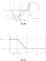
- Fig. 2A shows in more details the speed profile of the punch 22 during the setting step.
- the X-axis represents the time and the Y-axis represents the punch speed.
- Fig. 2A shows two curves.
- the plain line curve corresponds to the speed command. It is the pre-programmed punch speed.
- the dotted line corresponds to the actual punch speed.
- the two curve profiles are very similar, notably due to the sensors and monitoring unit explained above.
- the punch speed is constantly increased until it reaches a plateau.
- the plateau corresponds to a maximal punch speed used to approach the rivet.
- the maximal punch speed is for instance the first punch speed S1.
- the punch speed is then decreased up to the second punch speed S2.
- the second punch speed S2 corresponds to the second plateau.
- the inflexion point between the second plateau S1 and the curve portion corresponding to the decreasing speed corresponds to the predetermined maximal rivet length. Indeed, as mentioned below the predetermined maximal rivet length determines the instant when the second punch speed S2 is reached.
- Fig. 2B shows the pre-programmed punch speed as visible in fig. 2A in plain line and the dotted line show the rectification tool force during the setting step.
- the rectification tool force is calculated by the monitoring unit and the control device via the measurement of the first and second sensors.
- the rectification tool force allows to correct in real time the position of the punch and the rivet and their speed such that the actual and target curve are sensibly similar, as visible in fig. 2A .
- Fig. 3A and Fig. 3B show the punch speed in function of the relative punch position.
- the X-axis represents the relative punch position
- the Y-axis represents the speed.
- the curves in Fig. 3A and Fig. 3B only depicts the first stage R1, second stage R2 and third stage R3 of the setting step. The curves do not represent the return of the punch to its initial position after the setting of the rivet.
- the plain line curve represents the commanded relative punch position
- the dotted line curve represents the actual relative punch position.
- the command and actual curved are sensibly similar.
- the first stage R1 represented in the right-hand side of Fig. 3A
- the first plateau shows the first punch speed S1, which then slowly decreases in the second stage to reach the second punch speed, lower than the first punch speed.
- the second punch speed S2 forms the second plateau and corresponds to the third stage.
- the punch speed reduction from the first punch speed S1 to the second punch speed S2 can be sensibly constant.
- Fig. 3B shows the commanded relative punch position in plain line, as visible in Fig.
- the rectification tool force allows to correct in real time the position of the punch and the rivet and their speed such that the actual and target curve are sensibly similar, as visible in Fig. 3A .
Landscapes
- Engineering & Computer Science (AREA)
- Mechanical Engineering (AREA)
- Insertion Pins And Rivets (AREA)
Abstract
- Providing a setting tool (12) comprising a frame (20), a punch (22) that is displaceable on the frame along a joining axis (X), a die (28) that is mounted on the frame, and a clamping device (30) with which one or more components can be compressed in a joining direction, the punch being guided in the clamping device by a drive unit (24);
- Defining a predetermined maximal rivet setting speed,
- Providing a self-piercing rivet (18) comprising a length inferior to the predetermined maximal rivet length,
- Feeding the rivet into the setting tool (12),
- Setting the rivet (18) such that:
∘ in a first stage the punch (22) moves at a first punch speed (S1);
∘ in a second stage the punch speed decreases until it reaches a second punch speed (S2), wherein the second punch speed is reached at the latest when the rivet first contacts the workpiece, the second punch speed being lower than the first punch speed,
∘ in a third stage the punch continues moving and the rivet speed is monitored to ensure it does not exceed the predetermined maximal rivet setting speed.
Description
- The present invention relates to the setting of rivets. More particularly, the present invention relates to a joining method for connecting at least two workpieces with a rivet adapted to reduce the risk of cracking in the rivet.
- Self-piercing riveting (SPR) is a spot-joining technique in which a self-piercing rivet is driven, by a punch, into a layered workpiece supported on a die. The die is shaped so that as the rivet is driven into the workpiece towards the die, the material of the workpiece plastically deforms. This flow of workpiece material causes the annular tip of the rivet to flare outwards and remain encapsulated by an upset annulus of the workpiece material. The flared tip of the rivet interlocking with the upset annulus of the workpiece prevents removal of the rivet or separation of the layers of the workpiece.
- Insertion of a rivet into the workpiece is performed using a drive unit with an actuator (for instance a linear actuator such as a hydraulic cylinder or an electric linear actuator) which is mounted on a support arm of a force reaction frame opposite a die (or anvil) mounted on another support arm of the force reaction frame. The linear actuator drives the punch and rivet towards a stationary workpiece and die. The large forces on a workpiece which occur when a rivet is set or during punching must be compensated by a counterforce. This is usually achieved by supporting the workpiece on a counterforce structure, which preferably substantially has the shape of a C and is therefore also usually designated as a C-frame.
- For the precise setting of a rivet or accurate punching it is important to know how deeply a rivet or a die has penetrated into the workpiece.
EP1228824A2 is directed to a method for riveting or punching dealing with this issue. More particularly, the deformation of the counterforce structure during a riveting or punching process is detected by a monitoring unit and a course of movement during the riveting or punching process is corrected as a function of the bending. - Experience shows that some rivets tend to crack during a setting step. More particularly, the rivet (or more particularly self-piercing rivet) may crack in the joining direction, notably when the bore of the self-piercing rivet is filled. These cracks then widen until the rivet reaches its final position. The tendency to crack formation depends, among other things, on the following factors: rivet length, rivet coating, hardness of the sheet to be riveted. Several developments have been made to overcome this issue.
EP2631022A1 andEP3424611 for instance are directed to an improved die.US2020261966A1 is directed to an improved self-piercing rivet. - However, a need still exists to improve the setting of rivets, and notably to provide joining method which reduces the risk of damage in the fastener, like for instance the risk of cracking in the self-piercing rivet, notably without significant impact on cycle time and which works also for fasteners being mechanically coated. Examples of the present disclosure aim to address the aforementioned problems.
- According to an aspect of the present disclosure there is a joining method for connecting at least two workpieces with a rivet comprising the steps of:
- Providing a setting tool comprising a frame, a punch that is displaceable on the frame along a joining axis, a die that is mounted on the frame, and a clamping device with which one or more components can be compressed in a joining direction, the punch being guided in the clamping device by a drive unit;
- Defining a predetermined maximal rivet setting speed;
- Providing a rivet comprising a length inferior to the predetermined maximal rivet length;
- Feeding the rivet into the setting tool;
- Setting the rivet such that in a first stage the punch moves at a first punch speed; in a second stage the punch speed decreases until it reaches a second punch speed, wherein the second punch speed is reached at the latest when the rivet first contacts the workpiece, the second punch speed being lower than the first punch speed; in a third stage the punch continues moving and the rivet speed is monitored to ensure it does not exceed the predetermined maximal rivet setting speed.
- Such method with a controlled speed decrease and the definition of a predetermined maximal rivet setting speed which is not exceeded during the setting of the rivet allows to reduce the risk of cracks in the rivet. More particularly, it must be guaranteed, that the setting speed, from rivet contact point up to the end of the setting process is lower or equal to the defined setting speed. The defined maximum rivet length allows to keep the speed of the punch to a maximum up until it is reached, such that a faster punch speed is mostly used during the joining method. A faster punch speed is indeed advantageous for effective cycle times of the joining process. The speed reduction allows to avoid or sensibly decrease the cracks. The rivet speed is monitored to ensure an exact control of the process.
- In an embodiment, the method further comprises the step of defining a predetermined maximal rivet length, and wherein the second punch speed is reached when the punch arrives at a position which corresponds to the predetermined maximal rivet length. The maximal rivet length is a point which is always reached before the rivet contact point and which can easily be indicated or defined by an operator. The maximal rivet length can be adjusted by an operator.
- In an embodiment, the first punch speed is within a range of 150-1000 mm/s. This enables effective cycle times of the joining process.
- In an embodiment, the second punch speed and/or the maximal predetermined rivet setting speed is within a range of 10-300 mm/s. In an embodiment, the maximal predetermined rivet setting speed is below 100 mm/s, or even below 50 mm/s. This allows to reduce the risks of crack, notably for self-piercing rivets having a mechanical coating.
- In an embodiment, the drive unit decreases the punch speed such that the predetermined maximal rivet setting speed is reached when the predetermined maximal rivet length is reached. For instance, the speed decrease is constant such that a smooth transition is realized, the lower speed is reached only at the maximal rivet length or when the rivet first contacts the workpiece and the effective cycle time is not affected. Indeed, lower speed always increases the cycle time. The present method aims to have a minimal effect on the cycle time. The method can thus be used for a wide range of rivets having a length inferior to the pre-defined maximal rivet length.
- In an embodiment, the second punch speed is correlated to the predetermined maximal rivet setting speed so that the predetermined maximal rivet setting speed is reached when the predetermined maximal rivet length is reached or when the rivet first contacts the workpiece.
- In an embodiment, the deformation of the frame during the setting step is detected by a monitoring unit and a course of movement during the setting step is corrected as a function of the deformation. Thus, the exact position of the rivet with regard to the workpiece can be determine and therefore the rivet speed can be monitored and controlled. In an embodiment, the rivet speed could also be monitored without the knowledge of the workpiece position, but such monitoring is less accurate.
- In an embodiment, a relative movement between the frame and clamping device is measured by a first sensor and a relative movement between the frame and the punch is measured by a second sensor. The two sensors can easily be implemented and allows to exactly determine the rivet speed.
- In an embodiment, the first sensor and/or the second sensor is a linear path recorder, preferably a digital counter. For example, the digital counter counts stroke-shaped markings on a kind of ruler. This enables fast and accurate processing of the signals in a monitoring unit. In another embodiment, other systems like for instance laser can be used.
- In an embodiment, the first and/ or the second workpieces is a high strength steel workpiece. Components made of high strength steel are known to be difficult to join to each other or to other metals. Such high strength steel can, in some cases, have a tensile strength of at least 400 MPa. In another embodiment, the workpieces or at least one of the workpiece are/is made with thick (at least 3mm) mild steels or hard aluminum alloys.
- In another embodiment, three workpieces are joined, and the two upper layers are high strength steel workpieces.
- In an embodiment, the predetermined maximal rivet setting speed is adjustable. Thus, depending on the rivet, the workpiece and the nature of the joint, the maximal rivet setting speed can be adjusted by an operator to optimize the cycle time while avoiding cracks.
- Various other aspects and further examples are also described in the following detailed description and in the attached claims with reference to the accompanying drawings, in which:
-
Fig. 1 schematically shows a setting tool comprising a frame, a punch that is displaceable on the frame along a joining axis, a die that is mounted on the frame, and a clamping device with which one or more components can be compressed in a joining direction, the punch being guided in the clamping device by a drive unit; -
Fig. 2A shows a schematic diagram of the commanded and actual punch speed profile during the joining method; -
Fig. 2B shows the schematic diagram ofFig. 2A with the commanded punch speed profile and the tool rectification force profile measured and used to command a precise setting; -
Fig. 3A shows a schematic diagram of the punch speed in function of the relative punch position; -
Fig. 3B shows the schematic diagram ofFig. 3A with the punch speed in function of the relative punch position and the tool rectification force profile measured and used to command a precise setting. - The embodiments of the disclosure will be best understood by reference to the drawings, wherein the same reference signs designate identical or similar elements. It will be readily understood that the components of the disclosed embodiments, as generally described and illustrated in the figures herein, could be arranged and designed in a wide variety of different configurations. The steps of a method do not necessarily need to be executed in any specific order, or even sequentially, nor need the steps be executed only once, unless otherwise specified.
- In some cases, well-known features, structures, or operations are not shown or described in detail. Furthermore, the described features, structures, or operations may be combined in any suitable manner in one or more embodiments. It will also be readily understood that the components of the embodiments, as generally described and illustrated in the figures herein, could be arranged and designed in a wide variety of different configurations.
-
Fig. 1 schematically shows a joiningarrangement 10 for carrying out the joining method. The joiningarrangement 10 comprises asetting tool 12. Thesetting tool 12 comprises a joining head which either can be mounted in a stationary fashion or can be moved by means of arobot 14. A feeder arrangement with afeeder hose 16 can be provided. Thefeeder hose 16 feeds singulatedrivets 18 to the joining head, for example by means of air blast. Alternatively, a feeder arrangement can also have a magazine on the joining head, which is used to transfer singulated rivets automatically into a holder. - The joining head further comprises a counterforce structure or
frame 20. Typically,such frame 20 is a C-shaped frame composed of a solid material. Apunch 22 displaceable on theframe 20 along a joining axis X is also provided. Thepunch 22 can be controlled by a drive unit 24 and a control device 26. The drive unit 24 may comprise an actuator to actuate thepunch 22. - The joining head further comprises a die 28 that is mounted on the
frame 20, and aclamping device 30. Thedie 28 is mounted at one end of theframe 20, wherein theclamping device 30 is mounted at the other end of theframe 20. Thepunch 22 is guided in theclamping device 30 by the drive unit 24. The clampingdevice 30 is adapted to be biased in the joining direction or in the direction of thedie 28. - The joining
arrangement 10 serves to connect afirst workpiece 32 and asecond workpiece 34 which, for example, can be designed as metal sheets, by arivet 18. Thesetting tool 12 can also be used to join together more than twoworkpieces rivet 18 can be for example a self-piercingrivet 18 or punch rivet which can be a hollow or a semi-hollow punch rivet. Theworkpieces rivet 18 can for instance be mechanically coated or galvanic coated for instance. Therivet 18 can be a self-piercing rivet as described inEP3080463 A1 orEP2470799 A1 . - To set the
rivet 18 in theworkpieces workpieces die 28. Thepunch 22 is then moved by means of the drive unit 24 in the direction toward thedie 28. In this case, the clampingdevice 30 first contacts a surface of theuppermost workpiece 32 and presses theworkpieces - The
punch 22 is driven in a first stage R1 at a first punch speed S1. The first punch speed S1 is for instance between 150 and 1000 mm/s. The first punch speed S1 can be constant or not. More particularly the first punch speed S1 can be raised to a particular maximal value, for instance 300mm/s. The first punch speed S1 is commanded by the control device 26. Thepunch 22 is driven at the first punch speed S1 by the drive unit 24 and then the punch speed decreases until the punch reaches a position which corresponds to the given maximal rivet length. The punch speed slowly decreases from the first punch speed S1 to a second punch speed S2 such that as soon as the punch reaches the position corresponding to the predetermined maximal rivet length, it reaches the second punch speed S2. The punch speed reduction corresponds to a second stage R2. The second punch speed S2 is for instance a constant speed or sensibly constant speed. The second punch speed S2 is lower than the first punch speed S1. - During the motion of the
punch 22 toward thedie 28, thepunch 22 contacts the head of the rivet and therefore drive the rivet into the workpiece arrangement to realize the connection. This stage corresponds to a third stage R3, during which thepunch 22 drives therivet 18 into the workpiece at the second punch speed and the rivet speed is monitored to ensure it does not exceed a predetermined maximal rivet setting speed. The predetermined maximal rivet setting speed is a data which is defined by the operator before the joining method in the control device. The predetermined maximal rivet setting speed and the second punch speed are correlated. The predetermined maximal rivet setting speed can be adjusted by an operator depending on the joining operation, the workpiece material, the rivet material, the rivet geometry, the die geometry, ... For instance, with a mechanically coated rivet, the predetermined maximal rivet setting speed is within a range of 10-300 mm/s. The predetermined maximal rivet setting speed can be below 100mm/s, or even below 50 mm/s in a particular embodiment. - The predetermined maximal rivet length allows to ensure that the speed is decreased before or when the rivet contacts first the workpiece and therefore to determine when the punch speed needs to be decreased such that the lower punch speed to avoid the cracks on the rivet has a minimum impact on the cycle time.
- In order to correctly monitor the rivet speed during the setting step, the setting tool comprises a monitoring unit 36 adapted to detect the deformation of the
frame 20 during the setting process and a course of movement during the setting step can be corrected by the control device as a function of the deformation. Thus, the actual displacement of thepunch 22 and/ or therivet 18 can be determined, and the actual rivet speed correctly monitored. A first sensor 38 measures the relative movement between clampingdevice 30 andframe 20. This sensor is preferably a linear path recorder consisting of a kind of ruler which makes the same movement as the clamping device and a counter which is fixed to the frame and counts markings on the ruler going past it. Asecond sensor 40 measures the relative movement between frame and punch. - The first sensor 38 and the
second sensor 40 are connected to the monitoring unit 36, which can thereby detect the bending of the frame during action of force by thepunch 22 and theclamping device 30 on theworkpiece frame 20 detected in this way the movement of the punch can be adjusted in such a way that a constant penetration depth of the rivets is always ensured. More particularly, the position of the rivet with regard to the workpiece can always be measured. This allows to determine the exact punch position, but also the exact rivet speed and to monitor correctly that the rivet speed does not exceed the predetermined maximal rivet setting speed. The course of movement can thus be corrected by the control device during the riveting or setting or joining process as a function of the bending. -
Fig. 2A shows in more details the speed profile of thepunch 22 during the setting step. InFig. 2A the X-axis represents the time and the Y-axis represents the punch speed.Fig. 2A shows two curves. The plain line curve corresponds to the speed command. It is the pre-programmed punch speed. The dotted line corresponds to the actual punch speed. As visible inFig. 2A , the two curve profiles are very similar, notably due to the sensors and monitoring unit explained above. In an initial stage (not described in detail above), the punch speed is constantly increased until it reaches a plateau. The plateau corresponds to a maximal punch speed used to approach the rivet. The maximal punch speed is for instance the first punch speed S1. The punch speed is then decreased up to the second punch speed S2. The second punch speed S2 corresponds to the second plateau. The inflexion point between the second plateau S1 and the curve portion corresponding to the decreasing speed corresponds to the predetermined maximal rivet length. Indeed, as mentioned below the predetermined maximal rivet length determines the instant when the second punch speed S2 is reached. Once the rivet is set in the workpiece, thepunch 22 is then driven away from the workpiece and returns to its initial position as quickly as possible, as visible in the last portion (right-handed portion) of the curve shown inFig. 2A . A new rivet can be fed and a new setting step can then be undertaken on the same workpieces at a different area or on different workpieces. -
Fig. 2B shows the pre-programmed punch speed as visible infig. 2A in plain line and the dotted line show the rectification tool force during the setting step. The rectification tool force is calculated by the monitoring unit and the control device via the measurement of the first and second sensors. The rectification tool force allows to correct in real time the position of the punch and the rivet and their speed such that the actual and target curve are sensibly similar, as visible infig. 2A . -
Fig. 3A andFig. 3B show the punch speed in function of the relative punch position. InFig. 2A the X-axis represents the relative punch position, and the Y-axis represents the speed. Unlikefig. 2A andFig. 2 , the curves inFig. 3A andFig. 3B only depicts the first stage R1, second stage R2 and third stage R3 of the setting step. The curves do not represent the return of the punch to its initial position after the setting of the rivet. - In
Fig. 3A , the plain line curve represents the commanded relative punch position, and the dotted line curve represents the actual relative punch position. As visible, due to thesensors 38, 40 and the monitoring unit 36, the command and actual curved are sensibly similar. In the first stage R1, represented in the right-hand side ofFig. 3A , the first plateau shows the first punch speed S1, which then slowly decreases in the second stage to reach the second punch speed, lower than the first punch speed. The second punch speed S2 forms the second plateau and corresponds to the third stage. As seen inFig. 3A , the punch speed reduction from the first punch speed S1 to the second punch speed S2 can be sensibly constant.Fig. 3B shows the commanded relative punch position in plain line, as visible inFig. 3A and the dotted line show the rectification tool force at the different position of the punch. The rectification tool force allows to correct in real time the position of the punch and the rivet and their speed such that the actual and target curve are sensibly similar, as visible inFig. 3A . - joining
arrangement 10 - setting
tool 12 -
robot 14 -
feeder hose 16 - rivet 18
-
frame 20 -
punch 22 - joining axis X
- drive unit 24
- control device 26
- die 28
- clamping
device 30 -
first workpiece 32 -
second workpiece 34 - first punch speed S1
- second punch speed S2
- first stage R1
- second stage R2
- third stage R3
- monitoring unit 36
- first sensor 38
-
second sensor 40
Claims (13)
- Joining method for connecting at least two workpieces with a rivet comprising the steps of:- Providing a setting tool (12) comprising a frame (20), a punch (22) that is displaceable on the frame along a joining axis (X), a die (28) that is mounted on the frame, and a clamping device (30) with which one or more components can be compressed in a joining direction, the punch being guided in the clamping device by a drive unit (24);- Defining a predetermined maximal rivet setting speed,- Providing a rivet (18) comprising a length inferior to the predetermined maximal rivet length,- Feeding the rivet into the setting tool (12),- Setting the rivet (18) such that:∘ in a first stage the punch (22) moves at a first punch speed (S1);∘ in a second stage the punch speed decreases until it reaches a second punch speed (S2), wherein the second punch speed is reached at the latest when the rivet first contacts the workpiece, the second punch speed being lower than the first punch speed,∘ in a third stage the punch continues moving and the rivet speed is monitored to ensure it does not exceed the predetermined maximal rivet setting speed.
- Joining method according to claim 1, comprising the step of defining a predetermined maximal rivet length, and wherein the second punch speed is reached when the punch arrives at a position which corresponds to the predetermined maximal rivet length.
- Joining method according to claim 1 or 2, wherein the first punch speed (S1) is within a range of 150-1000 mm/s.
- Joining method according to any of claims 1 to 3, wherein the second punch speed (S2) and/or the maximal predetermined rivet setting speed is within a range of 10-300 mm/s.
- Joining method according to any of claims 1 to 3, wherein the predetermined maximal rivet setting speed is below 100 mm/s.
- Joining method according to any of claims 1 to 5, wherein the drive unit (24) decreases the punch speed such that the predetermined maximal rivet setting speed is reached when the rivet first contacts the workpiece.
- Joining method according to any of claims 1 to 6, wherein the second punch speed (S2) is correlated to the predetermined maximal rivet setting speed so that the predetermined maximal rivet setting speed is reached when the predetermined maximal rivet length is reached.
- Joining method according to any of claims 1 to 7, wherein the deformation of the frame (20) during the setting step is detected by a monitoring unit and a course of movement during the setting step is corrected as a function of the deformation.
- Joining method according to any of claims 1 to 8, wherein a relative movement between the frame (20) and clamping device (30) is measured by a first sensor (38) and a relative movement between the frame and the punch is measured by a second sensor (40).
- Joining method according to claim 9, wherein the first sensor (38) and/or the second sensor (40) is a linear path recorder, preferably a digital counter.
- Joining method according to any of the preceding claims, wherein the first and/ or the second workpieces (32, 34) is a high strength steel workpiece.
- Joining method according to any of the preceding claims, wherein three workpieces are joined, and the two upper layers are high strength steel workpieces.
- Joining method according to any of the preceding claims, wherein the predetermined maximal rivet setting speed is adjustable.
Priority Applications (4)
| Application Number | Priority Date | Filing Date | Title |
|---|---|---|---|
| EP23171215.9A EP4458490A1 (en) | 2023-05-03 | 2023-05-03 | Method of producing a riveted joint |
| US18/654,138 US20240367216A1 (en) | 2023-05-03 | 2024-05-03 | Method of producing a riveted joint |
| CN202410548505.5A CN118893171A (en) | 2023-05-03 | 2024-05-06 | Method for producing riveted joints |
| JP2024075287A JP2024170375A (en) | 2023-05-03 | 2024-05-07 | Manufacturing method of riveted joint |
Applications Claiming Priority (1)
| Application Number | Priority Date | Filing Date | Title |
|---|---|---|---|
| EP23171215.9A EP4458490A1 (en) | 2023-05-03 | 2023-05-03 | Method of producing a riveted joint |
Publications (1)
| Publication Number | Publication Date |
|---|---|
| EP4458490A1 true EP4458490A1 (en) | 2024-11-06 |
Family
ID=86328854
Family Applications (1)
| Application Number | Title | Priority Date | Filing Date |
|---|---|---|---|
| EP23171215.9A Pending EP4458490A1 (en) | 2023-05-03 | 2023-05-03 | Method of producing a riveted joint |
Country Status (4)
| Country | Link |
|---|---|
| US (1) | US20240367216A1 (en) |
| EP (1) | EP4458490A1 (en) |
| JP (1) | JP2024170375A (en) |
| CN (1) | CN118893171A (en) |
Citations (9)
| Publication number | Priority date | Publication date | Assignee | Title |
|---|---|---|---|---|
| EP1228824A2 (en) | 2001-01-15 | 2002-08-07 | Emhart LLC | Method for riveting or punching and a device for carrying out the method |
| US20040167660A1 (en) * | 1997-07-21 | 2004-08-26 | Dieter Mauer | Riveting system and process for forming a riveted joint |
| EP2470799A1 (en) | 2009-08-24 | 2012-07-04 | Newfrey LLC | Punch rivet, method for producing a punch rivet connection, and workpiece arrangement |
| EP2631022A1 (en) | 2012-02-21 | 2013-08-28 | Newfrey LLC | Die for self-piercing rivet fastening device |
| EP3080463A1 (en) | 2013-12-11 | 2016-10-19 | Newfrey LLC | Self-piercing rivet and self-piercing riveting method and self-piercing riveted joint |
| US20180185902A1 (en) * | 2015-07-01 | 2018-07-05 | Nippon Steel & Sumitomo Metal Corporation | Mechanical joining apparatus and mechanical joining method |
| US20180272419A1 (en) * | 2017-03-24 | 2018-09-27 | Böllhoff Verbindungstechnik GmbH | Multi-step joining device and joining method therefor |
| EP3424611A1 (en) | 2017-07-05 | 2019-01-09 | Newfrey LLC | Self-piercing rivet apparatus |
| US20200261966A1 (en) | 2019-02-20 | 2020-08-20 | Newfrey Llc | Heat resistant self-piercing rivet for inserting into heated advanced high strength metal |
Family Cites Families (2)
| Publication number | Priority date | Publication date | Assignee | Title |
|---|---|---|---|---|
| DE112016003710T5 (en) * | 2015-08-14 | 2018-06-14 | Magna International Inc. | SURFACE DESIGN FOR A STANZNIETKNOPFAUFBAU |
| GB2602978A (en) * | 2021-01-20 | 2022-07-27 | Atlas Copco Ias Uk Ltd | Computer implemented method for adjusting a fastener setting tool |
-
2023
- 2023-05-03 EP EP23171215.9A patent/EP4458490A1/en active Pending
-
2024
- 2024-05-03 US US18/654,138 patent/US20240367216A1/en active Pending
- 2024-05-06 CN CN202410548505.5A patent/CN118893171A/en active Pending
- 2024-05-07 JP JP2024075287A patent/JP2024170375A/en active Pending
Patent Citations (10)
| Publication number | Priority date | Publication date | Assignee | Title |
|---|---|---|---|---|
| US20040167660A1 (en) * | 1997-07-21 | 2004-08-26 | Dieter Mauer | Riveting system and process for forming a riveted joint |
| EP1228824A2 (en) | 2001-01-15 | 2002-08-07 | Emhart LLC | Method for riveting or punching and a device for carrying out the method |
| US20050081360A1 (en) * | 2001-01-15 | 2005-04-21 | Newfrey Llc | Method for riveting or piercing and a device for carrying out the method |
| EP2470799A1 (en) | 2009-08-24 | 2012-07-04 | Newfrey LLC | Punch rivet, method for producing a punch rivet connection, and workpiece arrangement |
| EP2631022A1 (en) | 2012-02-21 | 2013-08-28 | Newfrey LLC | Die for self-piercing rivet fastening device |
| EP3080463A1 (en) | 2013-12-11 | 2016-10-19 | Newfrey LLC | Self-piercing rivet and self-piercing riveting method and self-piercing riveted joint |
| US20180185902A1 (en) * | 2015-07-01 | 2018-07-05 | Nippon Steel & Sumitomo Metal Corporation | Mechanical joining apparatus and mechanical joining method |
| US20180272419A1 (en) * | 2017-03-24 | 2018-09-27 | Böllhoff Verbindungstechnik GmbH | Multi-step joining device and joining method therefor |
| EP3424611A1 (en) | 2017-07-05 | 2019-01-09 | Newfrey LLC | Self-piercing rivet apparatus |
| US20200261966A1 (en) | 2019-02-20 | 2020-08-20 | Newfrey Llc | Heat resistant self-piercing rivet for inserting into heated advanced high strength metal |
Also Published As
| Publication number | Publication date |
|---|---|
| JP2024170375A (en) | 2024-12-10 |
| US20240367216A1 (en) | 2024-11-07 |
| CN118893171A (en) | 2024-11-05 |
Similar Documents
| Publication | Publication Date | Title |
|---|---|---|
| EP2637813B1 (en) | Fastening method and apparatus | |
| US12121954B2 (en) | Setting tool for blind fasteners | |
| EP2845665B1 (en) | Punch rivet and also a method and apparatuses for attachment of individual components to one another of which at least one component is formed by a workpiece of composite material | |
| EP3829795B1 (en) | Riveting method | |
| WO2013152440A1 (en) | Automated percussive riveting system | |
| CN103079723A (en) | Joining method | |
| CN110961495A (en) | Bending robot plate positioning detection and alignment method | |
| US9421604B2 (en) | Fastener driving device | |
| US11951524B2 (en) | Adjustable joining machine | |
| US20240367216A1 (en) | Method of producing a riveted joint | |
| CN110586834B (en) | Pressure riveting equipment | |
| KR20210065623A (en) | Self piercing riveting device and self piercing riveting method | |
| WO2025051883A1 (en) | Joining device with clamping device and joining method | |
| KR101543244B1 (en) | Rivet feeding device and self piercing rivet system having the same | |
| WO2025051885A1 (en) | Self-pierce riveting tool and method for setting a self-piercing type rivet | |
| KR20150079289A (en) | Rivet feeding device and self piercing rivet system having the same | |
| EP3829796B1 (en) | Rivet insertion method and apparatus | |
| CN211276402U (en) | Press riveting equipment | |
| CN114035458A (en) | Bolt setting method for nail-shaped bolt and setting device with electronic control unit for implementing the bolt setting method | |
| EP4520453A1 (en) | Joining method and joining device for joining workpieces | |
| Wituschek et al. | Combination of versatile self-piercing riveting processes | |
| d Lechner | Combination of versatile self-piercing riveting processes |
Legal Events
| Date | Code | Title | Description |
|---|---|---|---|
| PUAI | Public reference made under article 153(3) epc to a published international application that has entered the european phase |
Free format text: ORIGINAL CODE: 0009012 |
|
| STAA | Information on the status of an ep patent application or granted ep patent |
Free format text: STATUS: THE APPLICATION HAS BEEN PUBLISHED |
|
| AK | Designated contracting states |
Kind code of ref document: A1 Designated state(s): AL AT BE BG CH CY CZ DE DK EE ES FI FR GB GR HR HU IE IS IT LI LT LU LV MC ME MK MT NL NO PL PT RO RS SE SI SK SM TR |
|
| STAA | Information on the status of an ep patent application or granted ep patent |
Free format text: STATUS: REQUEST FOR EXAMINATION WAS MADE |
|
| 17P | Request for examination filed |
Effective date: 20250506 |
|
| STAA | Information on the status of an ep patent application or granted ep patent |
Free format text: STATUS: EXAMINATION IS IN PROGRESS |
|
| 17Q | First examination report despatched |
Effective date: 20250925 |