EP4458456B1 - Ceramic membrane filtration assembly with sealing device and related methods - Google Patents
Ceramic membrane filtration assembly with sealing device and related methods Download PDFInfo
- Publication number
- EP4458456B1 EP4458456B1 EP24174997.7A EP24174997A EP4458456B1 EP 4458456 B1 EP4458456 B1 EP 4458456B1 EP 24174997 A EP24174997 A EP 24174997A EP 4458456 B1 EP4458456 B1 EP 4458456B1
- Authority
- EP
- European Patent Office
- Prior art keywords
- housing
- assembly
- membrane
- sealing device
- sealing
- Prior art date
- Legal status (The legal status is an assumption and is not a legal conclusion. Google has not performed a legal analysis and makes no representation as to the accuracy of the status listed.)
- Active
Links
Images


Classifications
-
- B—PERFORMING OPERATIONS; TRANSPORTING
- B01—PHYSICAL OR CHEMICAL PROCESSES OR APPARATUS IN GENERAL
- B01D—SEPARATION
- B01D63/00—Apparatus in general for separation processes using semi-permeable membranes
- B01D63/06—Tubular membrane modules
-
- B—PERFORMING OPERATIONS; TRANSPORTING
- B01—PHYSICAL OR CHEMICAL PROCESSES OR APPARATUS IN GENERAL
- B01D—SEPARATION
- B01D63/00—Apparatus in general for separation processes using semi-permeable membranes
- B01D63/06—Tubular membrane modules
- B01D63/066—Tubular membrane modules with a porous block having membrane coated passages
-
- B—PERFORMING OPERATIONS; TRANSPORTING
- B01—PHYSICAL OR CHEMICAL PROCESSES OR APPARATUS IN GENERAL
- B01D—SEPARATION
- B01D71/00—Semi-permeable membranes for separation processes or apparatus characterised by the material; Manufacturing processes specially adapted therefor
- B01D71/02—Inorganic material
- B01D71/05—Cermet materials
-
- B—PERFORMING OPERATIONS; TRANSPORTING
- B01—PHYSICAL OR CHEMICAL PROCESSES OR APPARATUS IN GENERAL
- B01D—SEPARATION
- B01D2201/00—Details relating to filtering apparatus
- B01D2201/62—Honeycomb-like
-
- B—PERFORMING OPERATIONS; TRANSPORTING
- B01—PHYSICAL OR CHEMICAL PROCESSES OR APPARATUS IN GENERAL
- B01D—SEPARATION
- B01D2313/00—Details relating to membrane modules or apparatus
- B01D2313/02—Specific tightening or locking mechanisms
- B01D2313/025—Specific membrane holders
-
- B—PERFORMING OPERATIONS; TRANSPORTING
- B01—PHYSICAL OR CHEMICAL PROCESSES OR APPARATUS IN GENERAL
- B01D—SEPARATION
- B01D2313/00—Details relating to membrane modules or apparatus
- B01D2313/04—Specific sealing means
- B01D2313/041—Gaskets or O-rings
-
- B—PERFORMING OPERATIONS; TRANSPORTING
- B01—PHYSICAL OR CHEMICAL PROCESSES OR APPARATUS IN GENERAL
- B01D—SEPARATION
- B01D2313/00—Details relating to membrane modules or apparatus
- B01D2313/08—Flow guidance means within the module or the apparatus
- B01D2313/083—Bypass routes
-
- B—PERFORMING OPERATIONS; TRANSPORTING
- B01—PHYSICAL OR CHEMICAL PROCESSES OR APPARATUS IN GENERAL
- B01D—SEPARATION
- B01D2313/00—Details relating to membrane modules or apparatus
- B01D2313/20—Specific housing
- B01D2313/201—Closed housing, vessels or containers
-
- B—PERFORMING OPERATIONS; TRANSPORTING
- B01—PHYSICAL OR CHEMICAL PROCESSES OR APPARATUS IN GENERAL
- B01D—SEPARATION
- B01D2313/00—Details relating to membrane modules or apparatus
- B01D2313/21—Specific headers, end caps
-
- B—PERFORMING OPERATIONS; TRANSPORTING
- B01—PHYSICAL OR CHEMICAL PROCESSES OR APPARATUS IN GENERAL
- B01D—SEPARATION
- B01D2313/00—Details relating to membrane modules or apparatus
- B01D2313/44—Cartridge types
-
- B—PERFORMING OPERATIONS; TRANSPORTING
- B01—PHYSICAL OR CHEMICAL PROCESSES OR APPARATUS IN GENERAL
- B01D—SEPARATION
- B01D2315/00—Details relating to the membrane module operation
- B01D2315/10—Cross-flow filtration
-
- B—PERFORMING OPERATIONS; TRANSPORTING
- B01—PHYSICAL OR CHEMICAL PROCESSES OR APPARATUS IN GENERAL
- B01D—SEPARATION
- B01D2321/00—Details relating to membrane cleaning, regeneration, sterilization or to the prevention of fouling
- B01D2321/04—Backflushing
-
- B—PERFORMING OPERATIONS; TRANSPORTING
- B01—PHYSICAL OR CHEMICAL PROCESSES OR APPARATUS IN GENERAL
- B01D—SEPARATION
- B01D46/00—Filters or filtering processes specially modified for separating dispersed particles from gases or vapours
- B01D46/24—Particle separators, e.g. dust precipitators, using rigid hollow filter bodies
- B01D46/2403—Particle separators, e.g. dust precipitators, using rigid hollow filter bodies characterised by the physical shape or structure of the filtering element
- B01D46/2418—Honeycomb filters
-
- B—PERFORMING OPERATIONS; TRANSPORTING
- B01—PHYSICAL OR CHEMICAL PROCESSES OR APPARATUS IN GENERAL
- B01D—SEPARATION
- B01D69/00—Semi-permeable membranes for separation processes or apparatus characterised by their form, structure or properties; Manufacturing processes specially adapted therefor
- B01D69/08—Hollow fibre membranes
-
- C—CHEMISTRY; METALLURGY
- C04—CEMENTS; CONCRETE; ARTIFICIAL STONE; CERAMICS; REFRACTORIES
- C04B—LIME, MAGNESIA; SLAG; CEMENTS; COMPOSITIONS THEREOF, e.g. MORTARS, CONCRETE OR LIKE BUILDING MATERIALS; ARTIFICIAL STONE; CERAMICS; REFRACTORIES; TREATMENT OF NATURAL STONE
- C04B38/00—Porous mortars, concrete, artificial stone or ceramic ware; Preparation thereof
- C04B38/0006—Honeycomb structures
Definitions
- the present embodiments relate to a ceramic membrane filtration assembly with sealing device and related methods.
- the assemblies can experience large range of temperatures which can affect the individual components within the assembly and their performance in the field.
- the filtration assembly has important sealing requirements which can also be affected during assembly.
- WO 2016/112121 A1 describes a filtration assembly includes a membrane housing and at least one membrane fixture device disposed in the housing. Each membrane fixture device has a plurality of membrane fixture members extending from fixture device inner surface, and each membrane fixture device has membrane openings between the membrane fixture members.
- the filtration assembly further includes a plurality of ceramic membranes each extending from a first membrane end portion to a second membrane end portion, and each first membrane end portion is disposed in one of the membrane openings, where the membrane fixture members fixture the membranes therein.
- WO 2015/072513 A1 describes an allegedly long-life filtration element that is inexpensive to manufacture, easily configured to have a large opening diameter, and comparatively low in terms of filtration resistance.
- the filtration element comprises porous ceramic bodies in which fluid through-holes are formed passing between a pair of facing surfaces, and a fluid to be treated is treated between the inner surfaces of the fluid through-holes and a peripheral surface sandwiched between the facing surfaces.
- a plurality of the porous bodies are disposed adjacent to each other interposed by spacer members so that a gap is formed in the space bounded by the peripheral surface.
- a ceramic membrane filtration assembly according to the present invention is defined by claim 1.
- a method of filtering water with the ceramic membrane filtration assembly according to the present invention is defined by claim 13. Further advantageous developments of the present invention are set out in the dependent claims.
- a ceramic membrane filtration assembly comprising a membrane assembly extending from a first membrane assembly end to a second membrane assembly end, where the membrane assembly is defined by a membrane assembly length, the membrane assembly including one or more membranes. At least one of the membranes has a plurality of channels therein, and the channels have channel ends.
- the filtration assembly further includes at least one sealing device coupled with the membrane assembly adjacent to at least one of the first and second membrane assembly ends, where the sealing device has an inner and outer perimeter.
- the sealing device has a sealing feature disposed along the outer perimeter, and the inner perimeter of the sealing device is sealed with a portion of the membrane assembly.
- the sealing device further includes structural members extending from an inner diameter of the sealing device.
- the structural members include an inner open section structural substantially aligned with a feed water input port.
- the structural members do not contact the membrane assembly ends such that a gap is between the structural members and the membrane assembly ends.
- the filtration assembly further includes a housing, the membrane assembly disposed within the housing, the housing having a first housing end and second housing end and a housing side therebetween, the housing having an outer circumference, the housing having an inner diameter, the sealing feature forms a seal between the housing and the sealing device.
- the sealing feature separates feedwater and permeate water.
- the housing has a feed port and at least one permeate output port.
- the at least one permeate output port exits the housing side.
- sealing between the sealing device and the housing occurs outside of the membrane assembly length.
- the filtration assembly further includes a first end cap disposed within the housing at a first end of the housing, the first end cap having a feed water input, a second end cap disposed within the housing at a second end of the housing, the second end cap having a concentrate port.
- the filtration assembly further includes two sealing devices, each sealing device disposed at each end of the housing, the permeate output port disposed between the two sealing devices fluidly separating permeate from feed water and concentrate solutions.
- the sealing device further includes a recessed portion disposed along the outer perimeter.
- the filtration assembly further includes a sealing member disposed within the recessed portion.
- the sealing device is coupled with the membrane such that there is an axial gap disposed between an end planar surface of the sealing device and the membrane assembly.
- An axial direction is defined by an axial direction of the channels.
- the sealing feature comprises an O-ring.
- the sealing feature comprises two O-rings.
- a method of filtering water with the ceramic membrane filtration assembly as described herein includes pumping feed water through the first end cap, through the first sealing device and into the channels of the membrane assembly, and releasing permeate though the permeate outlet port.
- the method further includes periodically interrupting pumping with a reverse flow to clean the membrane assembly.
- the method further includes releasing concentrate through a concentrate port while segregating the feed water from the permeate and the concentrate with the sealing device.
- the present embodiments relate to a ceramic membrane filtration assembly 100 which includes membrane module assembly 120, one or more sealing devices 180, and one or more end caps 150 ( FIGs. 1, 3 ).
- the ceramic membrane filtration assembly 100 can be used for fluid processing and/or separation applications, for example, to treat water in a water treatment plant.
- the filtration assembly 100 can be loaded in a basin, used for membrane bioreactor, used for waste affluence, or used in other process separation applications.
- the filtration assembly 100 includes a membrane assembly 120 and a housing 110, where the housing 110 receives the membrane assembly 120 therein.
- the housing 110 extends from a first housing 111 end to a second housing end 113, and has a housing side 115, and a housing outer circumference.
- the housing 110 includes one or more permeate outlet ports 130 and a feed port 132 therein.
- the at least one permeate output port exits the housing side.
- the housing 110 is defined in part by an external housing surface 114 and an internal housing surface 116.
- the ends 111, 113 of the housing 110 can be sealed with an end cap 150.
- a first end cap 152 is disposed at an end 111 of the housing 110.
- the first end cap 152 has a feed water input 156 into which untreated water flows, such as feed water.
- a first end cap 152 is disposed at end 111 of the housing 110, and a second end cap 154 is disposed at second end 113 of the housing.
- the second end cap 154 has a concentrate port 158, through which concentrate flows in the direction of the arrow.
- the membrane assembly 120 includes one or more membranes 122 ( FIG. 6 ).
- the membrane assembly 120 in one or more embodiments, includes one or more of elongate membranes, tubular membranes, flat membranes, or plate membranes.
- the one or more membranes 122 extend from a first membrane end 121 to a second membrane end 123.
- the membranes 122 include one or more channels 128 therein.
- the membrane assembly 120 has a membrane assembly length 126, and extends from a first membrane assembly end 118 to a second membrane assembly end 119.
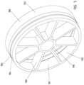
- the filtration assembly further includes at least one sealing device 180, as shown in FIGs. 2 , 5 , and 6 .
- the sealing device 180 has a general ring shape, defined in part by a dimension r, where r is the radius of the sealing device 180.
- the sealing device 180 is further defined by an inner surface 192 and an outer surface 194.
- the sealing device 180 is further defined by an inner perimeter and an outer perimeter.
- the at least one sealing device 180 further optionally includes a sealing portion 184, such as sealing features 187.
- the at least one sealing device 180 includes two or more sealing portions 184 or two different recessed portions.
- the sealing portion 184 includes a groove or recessed portion, for example, for an O-ring or elastomer.
- two O-rings 185 are disposed in two different sealing portions 184.
- a seal can be further included, such as an elastomeric seal, and is disposed within the groove or recessed portion.
- various shaped seals can be included such as conical seals, wedge shaped seals, O-rings, L-shaped seals, U-cup, Quad seals, packings, boot seals, cup seals, dynamic or static seals, adhesives, bonding and potting materials, welds, or others, or a combination thereof.
- a multiple seal configuration can also be included. Sealing surfaces can also be located in the housing as well as on the sealing device 180.
- At least one sealing device 180 is disposed in the housing 110.
- a first sealing device 181 is disposed at the first housing end 111
- a second sealing device 183 is disposed at the second housing end 113.
- the sealing device 180 is sealed to the housing 110, such as to an internal housing surface and/or to the external housing surface.
- the sealing feature 187 separates feed water (untreated waster) and permeate (treated water).
- two sealing devices 181, 183 are disposed in the housing 110, and each sealing device disposed at each end of the housing.
- the permeate output port 130 is disposed between the two sealing devices 181, 183 fluidly separating permeate from feed water and concentrate solutions.
- sealing between the sealing device and housing occurs outside of the length 126 of the membrane assembly 120, as shown in FIG. 3 .
- the sealing device 180 includes one or more structural members 186. Within an inner diameter of the ring shape are the structural members 186, as shown in FIG. 5 . Each sealing device 180 has a plurality of structural members 186 extending from the inner surface 181, where the structural members 186 are defined by a length 164. Other structural shapes could be used to reinforce the circumference of the sealing structure, provided they properly distributed the flow and properly reinforced the outside of the seal holder.
- the seal holder could also be a multiple piece assembly.
- the structural members 186 extend from an inner surface 181 and meet a center ring 190 of the sealing device. The structural members 186 assist in uniformly dispersing the feed water to the membrane assembly.
- the at least one sealing device 180 is sealing with the membrane assembly 120 at an end surface projection 178 of the at least one sealing device 180. Since the feed water can only enter the channels of the membrane assembly 120, the permeate exits from the membrane assembly 120 to the permeate port, and the sealing device 180 is sealed against the housing, sealing device 180 assists in preventing the feed water from mixing with the clean permeate.
- the end surface projection 178 is bonded with the membrane assembly 120.
- there is a gap 175 between the structural members and the membrane assembly allowing for improved flow during the operation of the filtration assembly since the structural members do not block the ends of the membrane assembly.
- the at least one sealing device 180 can be made by molding, printing, 3D printing, stamping, or machining, for example, from thermoplastic or metallic material.
- the sealing device 180 is formed of glass filled, metal, and/or ceramic material. This will assist with chemical and structural stability during temperature swings during manufacturing or use, as temperatures can move over 100 degrees F.
- a method of filtering water with the ceramic membrane filtration assembly as described herein includes pumping feed water in the through the first end cap, through the first sealing device and into the channels of the membrane assembly, and releasing permeate though the permeate outlet port.
- the method further includes periodically interrupting pumping with a reverse flow to clean the membrane assembly.
- the method further includes releasing concentrate through a concentrate port while segregating the feed water from the permeate and the concentrate with the sealing device.
- a ceramic membrane filtration assembly includes a housing having a first housing end and second housing end, where the housing has an outer circumference and an inner diameter, and at least one permeate output port.
- the filtration assembly further includes a membrane assembly that extends from a first membrane assembly end to a second membrane assembly end.
- the membrane assembly includes at least one membrane, where each membrane extends from a first membrane end to a second membrane end, and the membrane assembly is disposed within the housing.
- Each membrane has channels therein, and the channels have channel ends.
- the filtration assembly further includes a first and second end cap disposed within the housing at each end of the housing, where the first end cap has a feed water input, and the second end cap has a permeate output port.
- a sealing device is disposed at the first housing end near the first membrane assembly end of the membrane assembly, where the sealing device disposed between the membrane assembly and the end cap.
- the sealing device has an outer perimeter disposed adjacent to the inner diameter of the housing.
- the sealing device has a sealing feature disposed along the outer perimeter, where the sealing feature is sealed between the sealing device and the inner diameter of the housing, and the sealing device is sealed with an outer edge portion of the membrane assembly.
- the sealing device further includes structural members extending from an inner diameter of the sealing device.
- the structural members include an inner center circular structural substantially aligned with the feed water input port. In one or more embodiments, other geometric shapes could be used as structural members when they reinforce the outer circumference and allow proper distribution of flow to and from the membrane channels.
- the end cap and the sealing device are interfaced together.
- the end cap and sealing device are interfaced by one or more of snap fit, adhesive, or welding.
- the sealing member includes one or more filtrate gaps.
- the sealing device further includes a recessed portion disposed along the outer perimeter.
- a sealing member is disposed within the recessed portion.
- a ceramic membrane filtration assembly includes a housing having a first housing end and second housing end, where the housing has an outer circumference and an inner diameter, and a permeate output port.
- the assembly further includes a membrane assembly including at least one membrane, each of the at least one membrane extends from a first membrane end to a second membrane end, and the membrane assembly disposed within the housing.
- Each membrane has channels therein, and the channels have channel ends.
- a first end cap is disposed within the first housing end, and a second end cap is disposed within a second housing end. The first end cap has a feed water input, the second end cap has a concentrate port.
- a sealing device is disposed at each end of the membrane assembly, the sealing device disposed between the membrane assembly and each end cap, where the sealing devices have an outer perimeter disposed adjacent to the inner diameter of the housing.
- the sealing devices have a sealing feature disposed along the outer perimeter, the sealing feature is sealed with the inner diameter of the housing, and the sealing devices are sealed with ends of the membrane assembly.
- the sealing device further includes structural members extending from an inner diameter of the sealing device.
- the structural members include an inner center circular structural substantially aligned with the feed water input port.
- the end cap and the sealing device are interfaced together.
- the end cap and sealing device are interfaced by one or more of snap fit, adhesive, or welding.
- the sealing member includes one or more filtrate gaps.
- the sealing device further includes a recessed portion disposed along the outer perimeter.
- a sealing member is disposed within the recessed portion.
- a method of filtering water with the ceramic membrane filtration assembly includes pumping feed water in the through the first end cap, through the first sealing device, and into the channels of the membrane assembly, releasing permeate though the permeate outlet port, and releasing concentrate through the concentrate port while segregating the feed water from the permeate and the concentrate.
- a ceramic membrane filtration assembly comprising a membrane assembly extending from a first membrane assembly end to a second membrane assembly end, where the membrane assembly is defined by a membrane assembly length, the membrane assembly including at least one membrane. At least one of the membranes have channels therein, and at least one channel has channel ends.
- the filtration assembly further includes at least one sealing device coupled with the membrane assembly adjacent to at least one of the first and second membrane assembly ends, where the sealing device has an inner and outer perimeter.
- the sealing device has a sealing feature disposed along the outer perimeter, and the inner perimeter of the sealing device is sealed with a portion of the membrane assembly.
- the sealing device further includes structural members extending from an inner diameter of the sealing device.
- the structural members include an inner open section structural substantially aligned with a feed water input port.
- the structural members do not contact the membrane assembly ends such that a gap is between the structural members and the membrane assembly ends.
- the filtration assembly further includes a housing, the membrane assembly disposed within the housing, the housing having a first housing end and second housing end and a housing side therebetween, the housing having an outer circumference, the housing having an inner diameter, the sealing feature forms a seal between the housing and the sealing device.
- the sealing feature separates feedwater and permeate water.
- the housing has a feed port and at least one permeate output port.
- the at least one permeate output port exits the housing side.
- sealing between the sealing device and the housing occurs outside of the membrane assembly length.
- the filtration assembly further includes a first end cap disposed within the housing at a first end of the housing, the first end cap having a feed water input, a second end cap disposed within the housing at a second end of the housing, the second end cap having a concentrate port.
- the filtration assembly further includes two sealing devices, each sealing device disposed at each end of the housing, the permeate output port disposed between the two sealing devices fluidly separating permeate from feed water and concentrate solutions.
- the sealing device further includes a recessed portion disposed along the outer perimeter.
- the filtration assembly further includes a sealing member disposed within the recessed portion.
- the sealing device is coupled with the membrane such that there is a gap disposed between an end planar surface of the sealing device and the membrane assembly.
- the sealing feature comprises an O-ring.
- the sealing feature comprises two O-rings.
- a method of filtering water with the ceramic membrane filtration assembly as described herein includes pumping feed water in the through the first end cap, through the first sealing device and into the channels of the membrane assembly, and releasing permeate though the permeate outlet port.
- the method further includes releasing concentrate through a concentrate port while segregating the feed water from the permeate and the concentrate with the sealing device.
- the assembly facilitates the ease of element assembly, and helps control temperature expansion and will facilitate the use of drop in elements in standard housing.
- the sealing device allows for the contraction and expansion when a predetermined thermoplastic and fill material are used.
- the sealing device provides a place to hold a seal and provides a sealing surface.
- the fixture device aligns the ceramic membranes and allows the assembly to be efficiently assembled and sealed. It offers the benefit of allowing for expansion and contraction and facilitates external sealing of the membrane element to the wall of the housing in which it operates.
- the sealing used to separate the treated and untreated streams for example, permeate and feed water, overcomes inner diameter tolerance issues in standard housings.
- the sealing features, such as the multiple O-rings, are able to withstand the pressure differentials over a much longer period of time.
Landscapes
- Chemical & Material Sciences (AREA)
- Chemical Kinetics & Catalysis (AREA)
- Inorganic Chemistry (AREA)
- Separation Using Semi-Permeable Membranes (AREA)
Description
- The present embodiments relate to a ceramic membrane filtration assembly with sealing device and related methods.
- In the process of manufacturing filtration module assemblies, the assemblies can experience large range of temperatures which can affect the individual components within the assembly and their performance in the field. In addition, the filtration assembly has important sealing requirements which can also be affected during assembly. Still further, in the field there is limited amount of space for the filtration modules. What is needed is an improved method of manufacture of filtration assemblies, and improved filtration assemblies that address space constraints and cost of operating in the filtration assembly.
-
WO 2016/112121 A1 describes a filtration assembly includes a membrane housing and at least one membrane fixture device disposed in the housing. Each membrane fixture device has a plurality of membrane fixture members extending from fixture device inner surface, and each membrane fixture device has membrane openings between the membrane fixture members. The filtration assembly further includes a plurality of ceramic membranes each extending from a first membrane end portion to a second membrane end portion, and each first membrane end portion is disposed in one of the membrane openings, where the membrane fixture members fixture the membranes therein. -
WO 2015/072513 A1 describes an allegedly long-life filtration element that is inexpensive to manufacture, easily configured to have a large opening diameter, and comparatively low in terms of filtration resistance. The filtration element comprises porous ceramic bodies in which fluid through-holes are formed passing between a pair of facing surfaces, and a fluid to be treated is treated between the inner surfaces of the fluid through-holes and a peripheral surface sandwiched between the facing surfaces. A plurality of the porous bodies are disposed adjacent to each other interposed by spacer members so that a gap is formed in the space bounded by the peripheral surface. - A ceramic membrane filtration assembly according to the present invention is defined by claim 1. A method of filtering water with the ceramic membrane filtration assembly according to the present invention is defined by claim 13. Further advantageous developments of the present invention are set out in the dependent claims.
- According to the present invention, a ceramic membrane filtration assembly comprising a membrane assembly extending from a first membrane assembly end to a second membrane assembly end, where the membrane assembly is defined by a membrane assembly length, the membrane assembly including one or more membranes. At least one of the membranes has a plurality of channels therein, and the channels have channel ends. The filtration assembly further includes at least one sealing device coupled with the membrane assembly adjacent to at least one of the first and second membrane assembly ends, where the sealing device has an inner and outer perimeter. The sealing device has a sealing feature disposed along the outer perimeter, and the inner perimeter of the sealing device is sealed with a portion of the membrane assembly.
- In one or more embodiments, the sealing device further includes structural members extending from an inner diameter of the sealing device.
- In one or more embodiments, the structural members include an inner open section structural substantially aligned with a feed water input port.
- In one or more embodiments, the structural members do not contact the membrane assembly ends such that a gap is between the structural members and the membrane assembly ends.
- In one or more embodiments, the filtration assembly further includes a housing, the membrane assembly disposed within the housing, the housing having a first housing end and second housing end and a housing side therebetween, the housing having an outer circumference, the housing having an inner diameter, the sealing feature forms a seal between the housing and the sealing device.
- In one or more embodiments, the sealing feature separates feedwater and permeate water.
- In one or more embodiments, the housing has a feed port and at least one permeate output port.
- In one or more embodiments, the at least one permeate output port exits the housing side.
- In one or more embodiments, sealing between the sealing device and the housing occurs outside of the membrane assembly length.
- In one or more embodiments, the filtration assembly further includes a first end cap disposed within the housing at a first end of the housing, the first end cap having a feed water input, a second end cap disposed within the housing at a second end of the housing, the second end cap having a concentrate port.
- In one or more embodiments, the filtration assembly further includes two sealing devices, each sealing device disposed at each end of the housing, the permeate output port disposed between the two sealing devices fluidly separating permeate from feed water and concentrate solutions.
- In one or more embodiments, the sealing device further includes a recessed portion disposed along the outer perimeter.
- In one or more embodiments, the filtration assembly further includes a sealing member disposed within the recessed portion.
- According to the present invention, the sealing device is coupled with the membrane such that there is an axial gap disposed between an end planar surface of the sealing device and the membrane assembly. An axial direction is defined by an axial direction of the channels.
- In one or more embodiments, the sealing feature comprises an O-ring.
- In one or more embodiments, the sealing feature comprises two O-rings.
- According to the present invention, a method of filtering water with the ceramic membrane filtration assembly as described herein is provided, where the method includes pumping feed water through the first end cap, through the first sealing device and into the channels of the membrane assembly, and releasing permeate though the permeate outlet port.
- In one or more embodiments, the method further includes periodically interrupting pumping with a reverse flow to clean the membrane assembly.
- In one or more embodiments, the method further includes releasing concentrate through a concentrate port while segregating the feed water from the permeate and the concentrate with the sealing device.
- In the detailed description of the embodiments presented below, reference is made to the accompanying drawings, in which:
-
Figure 1 illustrates a side view of a ceramic filtration assembly in accordance with one or more embodiments. -
Figure 2 illustrates an end view of a ceramic filtration assembly in accordance with one or more embodiments. -
Figure 3 illustrates a cross-sectional view of a ceramic filtration assembly taken along 3-3 ofFIG. 1 . -
Figure 4 illustrates an enlarged view of a portion of the ceramic filtration assembly taken at 4 ofFIG. 1 . -
Figure 5 illustrates a perspective view of a sealing device in accordance with one or more embodiments. -
Figure 6 illustrates a cross-sectional perspective view of a ceramic filtration assembly in accordance with one or more embodiments. - The present embodiments are detailed below with reference to the listed figures.
- In the following detailed description, reference is made to the accompanying drawings which form part of the description, and in which is shown by way of illustration specific embodiments in which the embodiments may be practiced. These embodiments are described in sufficient detail to enable those skilled in the art to practice the invention, and it is to be understood that other embodiments may be practiced in other ways within the scope of the claims.
- The present embodiments relate to a ceramic
membrane filtration assembly 100 which includesmembrane module assembly 120, one ormore sealing devices 180, and one or more end caps 150 (FIGs. 1, 3 ). The ceramicmembrane filtration assembly 100 can be used for fluid processing and/or separation applications, for example, to treat water in a water treatment plant. In one or more examples, thefiltration assembly 100 can be loaded in a basin, used for membrane bioreactor, used for waste affluence, or used in other process separation applications. - The
filtration assembly 100 includes amembrane assembly 120 and ahousing 110, where thehousing 110 receives themembrane assembly 120 therein. Thehousing 110 extends from afirst housing 111 end to asecond housing end 113, and has ahousing side 115, and a housing outer circumference. In one or more embodiments, thehousing 110 includes one or morepermeate outlet ports 130 and a feed port 132 therein. In one or more embodiments, the at least one permeate output port exits the housing side. Thehousing 110 is defined in part by anexternal housing surface 114 and aninternal housing surface 116. - The
ends housing 110 can be sealed with anend cap 150. In one or more embodiments, afirst end cap 152 is disposed at anend 111 of thehousing 110. In one or more embodiments, thefirst end cap 152 has afeed water input 156 into which untreated water flows, such as feed water. In one or more embodiments, afirst end cap 152 is disposed atend 111 of thehousing 110, and asecond end cap 154 is disposed atsecond end 113 of the housing. In one or more embodiments, thesecond end cap 154 has aconcentrate port 158, through which concentrate flows in the direction of the arrow. - The
membrane assembly 120, shown inFIG. 3 , includes one or more membranes 122 (FIG. 6 ). Themembrane assembly 120, in one or more embodiments, includes one or more of elongate membranes, tubular membranes, flat membranes, or plate membranes. The one ormore membranes 122 extend from afirst membrane end 121 to asecond membrane end 123. Themembranes 122 include one ormore channels 128 therein. Themembrane assembly 120 has amembrane assembly length 126, and extends from a firstmembrane assembly end 118 to a secondmembrane assembly end 119. - The filtration assembly further includes at least one
sealing device 180, as shown inFIGs. 2 ,5 , and6 . In one or more embodiments, thesealing device 180 has a general ring shape, defined in part by a dimension r, where r is the radius of thesealing device 180. Thesealing device 180 is further defined by aninner surface 192 and an outer surface 194. Thesealing device 180 is further defined by an inner perimeter and an outer perimeter. - The at least one
sealing device 180 further optionally includes a sealingportion 184, such as sealing features 187. In one or more embodiments, the at least onesealing device 180 includes two ormore sealing portions 184 or two different recessed portions. In one or more embodiments, the sealingportion 184 includes a groove or recessed portion, for example, for an O-ring or elastomer. In one or more embodiments, two O-rings 185 are disposed in twodifferent sealing portions 184. A seal can be further included, such as an elastomeric seal, and is disposed within the groove or recessed portion. In one or more embodiments, various shaped seals can be included such as conical seals, wedge shaped seals, O-rings, L-shaped seals, U-cup, Quad seals, packings, boot seals, cup seals, dynamic or static seals, adhesives, bonding and potting materials, welds, or others, or a combination thereof. A multiple seal configuration can also be included. Sealing surfaces can also be located in the housing as well as on thesealing device 180. - At least one
sealing device 180 is disposed in thehousing 110. In one or more embodiments, afirst sealing device 181 is disposed at thefirst housing end 111, and asecond sealing device 183 is disposed at thesecond housing end 113. In one or more embodiments, thesealing device 180 is sealed to thehousing 110, such as to an internal housing surface and/or to the external housing surface. The sealingfeature 187 separates feed water (untreated waster) and permeate (treated water). In one or more embodiments, two sealingdevices housing 110, and each sealing device disposed at each end of the housing. Thepermeate output port 130 is disposed between the twosealing devices length 126 of themembrane assembly 120, as shown inFIG. 3 . - The
sealing device 180 includes one or morestructural members 186. Within an inner diameter of the ring shape are thestructural members 186, as shown inFIG. 5 . Each sealingdevice 180 has a plurality ofstructural members 186 extending from theinner surface 181, where thestructural members 186 are defined by a length 164. Other structural shapes could be used to reinforce the circumference of the sealing structure, provided they properly distributed the flow and properly reinforced the outside of the seal holder. The seal holder could also be a multiple piece assembly. - In one or more embodiments, the
structural members 186 extend from aninner surface 181 and meet acenter ring 190 of the sealing device. Thestructural members 186 assist in uniformly dispersing the feed water to the membrane assembly. - The at least one
sealing device 180 is sealing with themembrane assembly 120 at anend surface projection 178 of the at least onesealing device 180. Since the feed water can only enter the channels of themembrane assembly 120, the permeate exits from themembrane assembly 120 to the permeate port, and thesealing device 180 is sealed against the housing, sealingdevice 180 assists in preventing the feed water from mixing with the clean permeate. In one or more embodiments, theend surface projection 178 is bonded with themembrane assembly 120. In one or more embodiments, there is agap 175 disposed between the planar surface 177 of thesealing device 180 and the membrane assembly. In one or more embodiments, there is agap 175 between the structural members and the membrane assembly, allowing for improved flow during the operation of the filtration assembly since the structural members do not block the ends of the membrane assembly. - The at least one
sealing device 180 can be made by molding, printing, 3D printing, stamping, or machining, for example, from thermoplastic or metallic material. In one or more embodiments, thesealing device 180 is formed of glass filled, metal, and/or ceramic material. This will assist with chemical and structural stability during temperature swings during manufacturing or use, as temperatures can move over 100 degrees F. - In one or more embodiments, a method of filtering water with the ceramic membrane filtration assembly as described herein, where the method includes pumping feed water in the through the first end cap, through the first sealing device and into the channels of the membrane assembly, and releasing permeate though the permeate outlet port.
- In one or more embodiments, the method further includes periodically interrupting pumping with a reverse flow to clean the membrane assembly.
- In one or more embodiments, the method further includes releasing concentrate through a concentrate port while segregating the feed water from the permeate and the concentrate with the sealing device.
- In one or more embodiments, a ceramic membrane filtration assembly includes a housing having a first housing end and second housing end, where the housing has an outer circumference and an inner diameter, and at least one permeate output port. The filtration assembly further includes a membrane assembly that extends from a first membrane assembly end to a second membrane assembly end. The membrane assembly includes at least one membrane, where each membrane extends from a first membrane end to a second membrane end, and the membrane assembly is disposed within the housing. Each membrane has channels therein, and the channels have channel ends.
- The filtration assembly further includes a first and second end cap disposed within the housing at each end of the housing, where the first end cap has a feed water input, and the second end cap has a permeate output port. A sealing device is disposed at the first housing end near the first membrane assembly end of the membrane assembly, where the sealing device disposed between the membrane assembly and the end cap. The sealing device has an outer perimeter disposed adjacent to the inner diameter of the housing. The sealing device has a sealing feature disposed along the outer perimeter, where the sealing feature is sealed between the sealing device and the inner diameter of the housing, and the sealing device is sealed with an outer edge portion of the membrane assembly.
- In one or more embodiments, the sealing device further includes structural members extending from an inner diameter of the sealing device.
- In one or more embodiments, the structural members include an inner center circular structural substantially aligned with the feed water input port. In one or more embodiments, other geometric shapes could be used as structural members when they reinforce the outer circumference and allow proper distribution of flow to and from the membrane channels.
- In one or more embodiments, the end cap and the sealing device are interfaced together.
- In one or more embodiments, the end cap and sealing device are interfaced by one or more of snap fit, adhesive, or welding.
- In one or more embodiments, the sealing member includes one or more filtrate gaps.
- In one or more embodiments, the sealing device further includes a recessed portion disposed along the outer perimeter.
- In one or more embodiments, a sealing member is disposed within the recessed portion.
- In one or more embodiments, a ceramic membrane filtration assembly includes a housing having a first housing end and second housing end, where the housing has an outer circumference and an inner diameter, and a permeate output port. The assembly further includes a membrane assembly including at least one membrane, each of the at least one membrane extends from a first membrane end to a second membrane end, and the membrane assembly disposed within the housing. Each membrane has channels therein, and the channels have channel ends. A first end cap is disposed within the first housing end, and a second end cap is disposed within a second housing end. The first end cap has a feed water input, the second end cap has a concentrate port. A sealing device is disposed at each end of the membrane assembly, the sealing device disposed between the membrane assembly and each end cap, where the sealing devices have an outer perimeter disposed adjacent to the inner diameter of the housing. The sealing devices have a sealing feature disposed along the outer perimeter, the sealing feature is sealed with the inner diameter of the housing, and the sealing devices are sealed with ends of the membrane assembly.
- In one or more embodiments, the sealing device further includes structural members extending from an inner diameter of the sealing device.
- In one or more embodiments, the structural members include an inner center circular structural substantially aligned with the feed water input port.
- In one or more embodiments, the end cap and the sealing device are interfaced together.
- In one or more embodiments, the end cap and sealing device are interfaced by one or more of snap fit, adhesive, or welding.
- In one or more embodiments, the sealing member includes one or more filtrate gaps.
- In one or more embodiments, the sealing device further includes a recessed portion disposed along the outer perimeter.
- In one or more embodiments, a sealing member is disposed within the recessed portion.
- In one or more embodiments, a method of filtering water with the ceramic membrane filtration assembly includes pumping feed water in the through the first end cap, through the first sealing device, and into the channels of the membrane assembly, releasing permeate though the permeate outlet port, and releasing concentrate through the concentrate port while segregating the feed water from the permeate and the concentrate.
- A ceramic membrane filtration assembly comprising a membrane assembly extending from a first membrane assembly end to a second membrane assembly end, where the membrane assembly is defined by a membrane assembly length, the membrane assembly including at least one membrane. At least one of the membranes have channels therein, and at least one channel has channel ends. The filtration assembly further includes at least one sealing device coupled with the membrane assembly adjacent to at least one of the first and second membrane assembly ends, where the sealing device has an inner and outer perimeter. The sealing device has a sealing feature disposed along the outer perimeter, and the inner perimeter of the sealing device is sealed with a portion of the membrane assembly.
- In one or more embodiments, the sealing device further includes structural members extending from an inner diameter of the sealing device.
- In one or more embodiments, the structural members include an inner open section structural substantially aligned with a feed water input port.
- In one or more embodiments, the structural members do not contact the membrane assembly ends such that a gap is between the structural members and the membrane assembly ends.
- In one or more embodiments, the filtration assembly further includes a housing, the membrane assembly disposed within the housing, the housing having a first housing end and second housing end and a housing side therebetween, the housing having an outer circumference, the housing having an inner diameter, the sealing feature forms a seal between the housing and the sealing device.
- In one or more embodiments, the sealing feature separates feedwater and permeate water.
- In one or more embodiments, the housing has a feed port and at least one permeate output port.
- In one or more embodiments, the at least one permeate output port exits the housing side.
- In one or more embodiments, sealing between the sealing device and the housing occurs outside of the membrane assembly length.
- In one or more embodiments, the filtration assembly further includes a first end cap disposed within the housing at a first end of the housing, the first end cap having a feed water input, a second end cap disposed within the housing at a second end of the housing, the second end cap having a concentrate port.
- In one or more embodiments, the filtration assembly further includes two sealing devices, each sealing device disposed at each end of the housing, the permeate output port disposed between the two sealing devices fluidly separating permeate from feed water and concentrate solutions.
- In one or more embodiments, the sealing device further includes a recessed portion disposed along the outer perimeter.
- In one or more embodiments, the filtration assembly further includes a sealing member disposed within the recessed portion.
- In one or more embodiments, the sealing device is coupled with the membrane such that there is a gap disposed between an end planar surface of the sealing device and the membrane assembly.
- In one or more embodiments, the sealing feature comprises an O-ring.
- In one or more embodiments, the sealing feature comprises two O-rings.
- In one or more embodiments, a method of filtering water with the ceramic membrane filtration assembly as described herein, where the method includes pumping feed water in the through the first end cap, through the first sealing device and into the channels of the membrane assembly, and releasing permeate though the permeate outlet port.
- In one or more embodiments, the method further includes periodically interrupting pumping with a reverse flow to clean the membrane assembly.
- In one or more embodiments, the method further includes releasing concentrate through a concentrate port while segregating the feed water from the permeate and the concentrate with the sealing device.
- The assembly facilitates the ease of element assembly, and helps control temperature expansion and will facilitate the use of drop in elements in standard housing. The sealing device allows for the contraction and expansion when a predetermined thermoplastic and fill material are used. In addition, the sealing device provides a place to hold a seal and provides a sealing surface.
- The fixture device aligns the ceramic membranes and allows the assembly to be efficiently assembled and sealed. It offers the benefit of allowing for expansion and contraction and facilitates external sealing of the membrane element to the wall of the housing in which it operates. The sealing used to separate the treated and untreated streams, for example, permeate and feed water, overcomes inner diameter tolerance issues in standard housings. The sealing features, such as the multiple O-rings, are able to withstand the pressure differentials over a much longer period of time.
- The embodiments have been described in detail with particular reference to certain embodiments thereof, but it will be understood that variations and modifications can be effected within the scope of the claims. It should be noted that embodiments or portions thereof discussed in different portions of the description or referred to in different drawings can be combined to form additional embodiments of the present invention within the scope of the claims.
Claims (15)
- A ceramic membrane filtration assembly (100) comprising:a membrane assembly (120) extending from a first membrane assembly end to a second membrane assembly end, the membrane assembly (120) defined by a membrane assembly length (126); the membrane assembly (120) including one or more membranes, at least one membrane (122) having a plurality of channels (128) therein, the channels having channel ends; andat least one sealing device (180) coupled with the membrane assembly (120) adjacent to at least one of the first and second membrane assembly ends; whereinthe sealing device (180) has an inner and outer perimeter,the sealing device (180) has a sealing feature (187) disposed along the outer perimeter, andthe inner perimeter of the sealing device (180) is sealed with a portion of the membrane assembly (120); andwherein the sealing device is coupled with the membrane (122) such that there is an axial gap (175) disposed between an end planar surface of the sealing device (180) and the membrane assembly (120), an axial direction being defined by an axial direction of the channels (128).
- The ceramic membrane filtration assembly (100) as recited in claim 1, wherein the sealing device (180) further includes structural members (186) extending from an inner diameter of the sealing device (180).
- The ceramic membrane filtration assembly (100) as recited in claim 2, wherein the structural members (186)include an inner open section structural substantially aligned with a feed water input port, ordo not contact the membrane assembly ends such that the gap (175) is between the structural members (186) and the membrane assembly ends.
- The ceramic filtration assembly (100) as recited in claims 1 - 3, further comprising a housing (110), the membrane assembly (120) disposed within the housing (110), the housing (110) having a first housing end (111) and second housing end (113) and a housing side (115) therebetween, the housing (110) having an inner diameter, the sealing feature (187) forms a seal between the housing (110) and the sealing device (180).
- The ceramic filtration assembly (100) as recited in claim 4, wherein the sealing feature (187) separates feed water and permeate water, and optionallywherein the housing (110) has a feed port (132) and at least one permeate output port (130), and optionallywherein the at least one permeate output port (130) exits the housing side.
- The ceramic membrane filtration assembly (100) as recited in claims 4-5, wherein sealing between the sealing device (180) and the housing (110) occurs outside of the membrane assembly length (126).
- The ceramic filtration assembly (100) as recited in any one of claims 4, 5, or 6, further comprising a first end cap (152) disposed within the housing (110) at a first end of the housing (111), the first end cap (152) having a feed water input (152), a second end cap (154) disposed within the housing at a second end of the housing (113), the second end cap (154) having a concentrate port (158).
- The ceramic filtration assembly (100) as recited in claim 4, further comprising two sealing devices (181, 183), each sealing device (181, 183) disposed at each end of the housing (111), the permeate output port (130) disposed between the two sealing devices (181, 183) fluidly separating permeate from feed water and concentrate solutions.
- The ceramic membrane filtration assembly (100) as recited in any one of claims 1 - 8,
wherein the sealing device (181, 183) further includes a recessed portion disposed along the outer perimeter. - The ceramic membrane filtration assembly (100) as recited in claim 9, further comprising a sealing member disposed within the recessed portion.
- The ceramic membrane filtration assembly (100) as recited in any one of claims 1 - 10, wherein the sealing feature (187) comprises an O-ring (185).
- The ceramic membrane filtration assembly (100) as recited in any one of claims 1 - 10, wherein the sealing feature (187) comprises two O-rings (185).
- A method of filtering water with the ceramic membrane filtration assembly (100) as recited in any one of claims 1-12, the method comprising:pumping feed water through the first end cap (152), through the first sealing device, and into the channels (128) of the membrane assembly (120); andreleasing permeate though the permeate outlet port (130).
- The method as recited in claim 13, further comprising periodically interrupting pumping with a reverse flow to clean the membrane assembly (120).
- The method as recited in claim 13, further comprising releasing concentrate through a concentrate port (158) while segregating the feed water from the permeate and the concentrate with the sealing device.
Applications Claiming Priority (3)
| Application Number | Priority Date | Filing Date | Title |
|---|---|---|---|
| US201662365221P | 2016-07-21 | 2016-07-21 | |
| EP17749004.2A EP3487608B1 (en) | 2016-07-21 | 2017-07-21 | Ceramic membrane filtration assembly with sealing device and related methods |
| PCT/US2017/043386 WO2018018013A1 (en) | 2016-07-21 | 2017-07-21 | Ceramic membrane filtration assembly with sealing device and related methods |
Related Parent Applications (1)
| Application Number | Title | Priority Date | Filing Date |
|---|---|---|---|
| EP17749004.2A Division EP3487608B1 (en) | 2016-07-21 | 2017-07-21 | Ceramic membrane filtration assembly with sealing device and related methods |
Publications (2)
| Publication Number | Publication Date |
|---|---|
| EP4458456A1 EP4458456A1 (en) | 2024-11-06 |
| EP4458456B1 true EP4458456B1 (en) | 2025-06-18 |
Family
ID=59523261
Family Applications (2)
| Application Number | Title | Priority Date | Filing Date |
|---|---|---|---|
| EP17749004.2A Active EP3487608B1 (en) | 2016-07-21 | 2017-07-21 | Ceramic membrane filtration assembly with sealing device and related methods |
| EP24174997.7A Active EP4458456B1 (en) | 2016-07-21 | 2017-07-21 | Ceramic membrane filtration assembly with sealing device and related methods |
Family Applications Before (1)
| Application Number | Title | Priority Date | Filing Date |
|---|---|---|---|
| EP17749004.2A Active EP3487608B1 (en) | 2016-07-21 | 2017-07-21 | Ceramic membrane filtration assembly with sealing device and related methods |
Country Status (7)
| Country | Link |
|---|---|
| US (1) | US12544719B2 (en) |
| EP (2) | EP3487608B1 (en) |
| CN (1) | CN109414654A (en) |
| AU (1) | AU2017298986B2 (en) |
| ES (2) | ES2988604T3 (en) |
| SG (1) | SG11201810388WA (en) |
| WO (1) | WO2018018013A1 (en) |
Families Citing this family (7)
| Publication number | Priority date | Publication date | Assignee | Title |
|---|---|---|---|---|
| US20160151743A1 (en) | 2014-05-08 | 2016-06-02 | Thetis Environmental Inc. | Potted flat sheet membrane filtration module |
| SG11201810388WA (en) | 2016-07-21 | 2018-12-28 | Nanostone Water Inc | Ceramic membrane filtration assembly with sealing device and related methods |
| DE102017131375B4 (en) * | 2017-12-28 | 2021-03-18 | Nanostone Water Gmbh | Transport unit for a filter module, as well as use for transporting a filter module |
| US11654401B2 (en) * | 2021-10-25 | 2023-05-23 | Generon Igs, Inc. | Gas separation membrane cartridge with clamshell retainer |
| CN113896545A (en) * | 2021-12-07 | 2022-01-07 | 广东金刚新材料有限公司 | Ceramic envelope for ceramic membrane and 3D printing forming method thereof |
| US20240189776A1 (en) * | 2022-12-13 | 2024-06-13 | Air Products And Chemicals, Inc. | Port for Membrane Module |
| WO2026015217A1 (en) * | 2024-07-08 | 2026-01-15 | Pall Corporation | Hollow fiber alignment devices, systems, and hollow fiber filter devices |
Family Cites Families (25)
| Publication number | Priority date | Publication date | Assignee | Title |
|---|---|---|---|---|
| US5304312A (en) | 1992-07-27 | 1994-04-19 | Eastman Kodak Company | Filter assembly includng filter unit having deformable sealing end caps |
| US6656362B1 (en) | 1998-06-18 | 2003-12-02 | Toray Industries, Inc. | Spiral reverse osmosis membrane element, reverse osmosis membrane module using it, device and method for reverse osmosis separation incorporating the module |
| FR2786109A1 (en) | 1998-11-19 | 2000-05-26 | Orelis | Filtration module containing at least one filter element with elastomeric seals |
| DE10322015B4 (en) | 2003-05-16 | 2007-01-18 | Itn Nanovation Gmbh | sealing arrangement |
| DK1656196T3 (en) * | 2003-08-25 | 2010-01-04 | Pall Corp | A filter device |
| JP4364143B2 (en) | 2005-03-08 | 2009-11-11 | 株式会社クボタ | Membrane element and membrane module with built-in membrane element |
| WO2007004265A1 (en) | 2005-06-30 | 2007-01-11 | Ngk Insulators, Ltd. | Filter, casing for filter, and method of assembling filter |
| CN2885393Y (en) | 2006-01-27 | 2007-04-04 | 天津市维信环境科技有限公司 | Hollow fiber ultrafiltration membrane module |
| DE102006060858A1 (en) | 2006-12-22 | 2008-09-04 | Fachhochschule Köln | Ceramic filter to separate over critical gasses from adsorbed compounds has ceramic tubes clamped each end with axial movement |
| TW201247297A (en) | 2011-03-29 | 2012-12-01 | Toray Industries | Spiral type separation membrane element and method for producing the same |
| DE102011080763A1 (en) | 2011-08-10 | 2013-02-14 | Ksm Water Gmbh | Filter device and a method of manufacture |
| CN104039428B (en) * | 2011-09-02 | 2017-06-06 | 纳米水公司 | For the sealing plate of membrane separation device |
| MY181802A (en) * | 2011-10-28 | 2021-01-07 | Jgc Corp | Fluid separation apparatus and method of selectively separating mixed fluid |
| CN202289882U (en) | 2011-10-31 | 2012-07-04 | 富阳梅伊韦尔环保设备有限公司 | Reverse osmosis membrane device |
| CN104470487B (en) * | 2012-05-21 | 2017-09-05 | 卡麦尔药物股份公司 | Protect cap |
| JP5829227B2 (en) * | 2012-09-28 | 2015-12-09 | 富士フイルム株式会社 | Acid gas separation module, acid gas separation device, and telescope prevention plate |
| BR112015020766A2 (en) * | 2013-02-28 | 2017-07-18 | Aqua Membranes Llc | laminated composition, membrane for incorporation into a laminated composition, permeable membrane system, method of producing a suitable laminated composition, method for producing a waterproof membrane system, and method of separating a fluid using a membrane system |
| CN203408632U (en) | 2013-06-14 | 2014-01-29 | 浙江玉泉环境工程有限公司 | Ultrafiltration membrane component |
| JP2015093268A (en) | 2013-11-14 | 2015-05-18 | 株式会社クボタ | Filtration element, filtration module, filtration component, and filtration processing unit |
| US11041565B2 (en) | 2013-11-19 | 2021-06-22 | 1934612 Ontario Inc. | Filtration methods, apparatus, and systems using a ceramic seal gasket |
| CN203663714U (en) | 2013-12-20 | 2014-06-25 | 浙江中凯瑞普环境工程股份有限公司 | Inorganic carbon membrane component |
| CN107206326A (en) * | 2015-01-06 | 2017-09-26 | 纳诺斯通水务公司 | Fixtures and related methods for membrane modules |
| CN204544007U (en) | 2015-03-11 | 2015-08-12 | 湖南澳维环保科技有限公司 | A kind of rolling membrane for water treatment element end cap |
| CN204619762U (en) | 2015-03-27 | 2015-09-09 | 浙江美易膜科技有限公司 | A kind of end cap and center water producing pipe membrane component |
| SG11201810388WA (en) | 2016-07-21 | 2018-12-28 | Nanostone Water Inc | Ceramic membrane filtration assembly with sealing device and related methods |
-
2017
- 2017-07-21 SG SG11201810388WA patent/SG11201810388WA/en unknown
- 2017-07-21 ES ES17749004T patent/ES2988604T3/en active Active
- 2017-07-21 CN CN201780039526.2A patent/CN109414654A/en active Pending
- 2017-07-21 EP EP17749004.2A patent/EP3487608B1/en active Active
- 2017-07-21 EP EP24174997.7A patent/EP4458456B1/en active Active
- 2017-07-21 ES ES24174997T patent/ES3041752T3/en active Active
- 2017-07-21 WO PCT/US2017/043386 patent/WO2018018013A1/en not_active Ceased
- 2017-07-21 AU AU2017298986A patent/AU2017298986B2/en active Active
- 2017-07-21 US US16/304,536 patent/US12544719B2/en active Active
Also Published As
| Publication number | Publication date |
|---|---|
| EP3487608C0 (en) | 2024-05-15 |
| AU2017298986A1 (en) | 2018-12-13 |
| US20190291056A1 (en) | 2019-09-26 |
| SG11201810388WA (en) | 2018-12-28 |
| WO2018018013A1 (en) | 2018-01-25 |
| US12544719B2 (en) | 2026-02-10 |
| EP3487608B1 (en) | 2024-05-15 |
| EP4458456A1 (en) | 2024-11-06 |
| AU2017298986B2 (en) | 2022-04-21 |
| EP3487608A1 (en) | 2019-05-29 |
| ES2988604T3 (en) | 2024-11-21 |
| CN109414654A (en) | 2019-03-01 |
| ES3041752T3 (en) | 2025-11-14 |
Similar Documents
| Publication | Publication Date | Title |
|---|---|---|
| EP4458456B1 (en) | Ceramic membrane filtration assembly with sealing device and related methods | |
| EP0810024B1 (en) | Membrane module assembly | |
| JP3356180B2 (en) | Apparatus for separating mixtures using stacked osmotic membrane elements | |
| CN102781556B (en) | Radial split ring seal for filtration systems | |
| KR20110102423A (en) | Fluid filter assembly including seal | |
| US7749382B2 (en) | Seal ring holder for membrane element and membrane element | |
| US5723047A (en) | Compressible filter element peripherally sealed by a settable material | |
| CN107530635B (en) | Sealed housing for a filter cassette | |
| KR102330548B1 (en) | Filtration methods, apparatus, and systems using a ceramic seal gasket | |
| US20180021732A1 (en) | Membrane assembly with end cap device and related methods | |
| US20180154313A1 (en) | Fixture device for membrane assembly and related methods | |
| US7261817B2 (en) | Filter module and device for static filtration of fluids with such a module | |
| WO2013139798A1 (en) | Membrane assembly | |
| US3294242A (en) | Filter assembly having filter elements with integral distributing and supporting means | |
| HK40002900A (en) | Ceramic membrane filtration assembly with sealing device and related methods | |
| CA3024832C (en) | Separation membrane module | |
| CN109985524B (en) | Filter and method for manufacturing the same | |
| JP2002224505A (en) | Filter cartridge | |
| JP7122928B2 (en) | Hollow fiber membrane module | |
| JP7548457B1 (en) | Flat Membrane Module | |
| US20190060837A1 (en) | Spiral wound separation membrane module | |
| KR101777314B1 (en) | Hollow fiber membrane module |
Legal Events
| Date | Code | Title | Description |
|---|---|---|---|
| PUAI | Public reference made under article 153(3) epc to a published international application that has entered the european phase |
Free format text: ORIGINAL CODE: 0009012 |
|
| STAA | Information on the status of an ep patent application or granted ep patent |
Free format text: STATUS: REQUEST FOR EXAMINATION WAS MADE |
|
| 17P | Request for examination filed |
Effective date: 20240508 |
|
| AC | Divisional application: reference to earlier application |
Ref document number: 3487608 Country of ref document: EP Kind code of ref document: P |
|
| AK | Designated contracting states |
Kind code of ref document: A1 Designated state(s): AL AT BE BG CH CY CZ DE DK EE ES FI FR GB GR HR HU IE IS IT LI LT LU LV MC MK MT NL NO PL PT RO RS SE SI SK SM TR |
|
| GRAP | Despatch of communication of intention to grant a patent |
Free format text: ORIGINAL CODE: EPIDOSNIGR1 |
|
| STAA | Information on the status of an ep patent application or granted ep patent |
Free format text: STATUS: GRANT OF PATENT IS INTENDED |
|
| INTG | Intention to grant announced |
Effective date: 20250108 |
|
| GRAS | Grant fee paid |
Free format text: ORIGINAL CODE: EPIDOSNIGR3 |
|
| GRAA | (expected) grant |
Free format text: ORIGINAL CODE: 0009210 |
|
| STAA | Information on the status of an ep patent application or granted ep patent |
Free format text: STATUS: THE PATENT HAS BEEN GRANTED |
|
| AC | Divisional application: reference to earlier application |
Ref document number: 3487608 Country of ref document: EP Kind code of ref document: P |
|
| AK | Designated contracting states |
Kind code of ref document: B1 Designated state(s): AL AT BE BG CH CY CZ DE DK EE ES FI FR GB GR HR HU IE IS IT LI LT LU LV MC MK MT NL NO PL PT RO RS SE SI SK SM TR |
|
| REG | Reference to a national code |
Ref country code: GB Ref legal event code: FG4D |
|
| REG | Reference to a national code |
Ref country code: CH Ref legal event code: EP |
|
| REG | Reference to a national code |
Ref country code: DE Ref legal event code: R096 Ref document number: 602017090101 Country of ref document: DE |
|
| REG | Reference to a national code |
Ref country code: CH Ref legal event code: EP |
|
| REG | Reference to a national code |
Ref country code: IE Ref legal event code: FG4D |
|
| P01 | Opt-out of the competence of the unified patent court (upc) registered |
Free format text: CASE NUMBER: APP_31776/2025 Effective date: 20250701 |
|
| PGFP | Annual fee paid to national office [announced via postgrant information from national office to epo] |
Ref country code: NL Payment date: 20250724 Year of fee payment: 9 |
|
| REG | Reference to a national code |
Ref country code: DE Ref legal event code: R081 Ref document number: 602017090101 Country of ref document: DE Owner name: ACURIANT TECHNOLOGIES, INC., BOSTON, US Free format text: FORMER OWNER: NANOSTONE WATER INC., WALTHAM, MA, US |
|
| RAP4 | Party data changed (patent owner data changed or rights of a patent transferred) |
Owner name: ACURIANT TECHNOLOGIES, INC. |
|
| REG | Reference to a national code |
Ref country code: NL Ref legal event code: FP |
|
| PG25 | Lapsed in a contracting state [announced via postgrant information from national office to epo] |
Ref country code: FI Free format text: LAPSE BECAUSE OF FAILURE TO SUBMIT A TRANSLATION OF THE DESCRIPTION OR TO PAY THE FEE WITHIN THE PRESCRIBED TIME-LIMIT Effective date: 20250618 |
|
| PGFP | Annual fee paid to national office [announced via postgrant information from national office to epo] |
Ref country code: ES Payment date: 20250807 Year of fee payment: 9 |
|
| PGFP | Annual fee paid to national office [announced via postgrant information from national office to epo] |
Ref country code: DE Payment date: 20250722 Year of fee payment: 9 |
|
| REG | Reference to a national code |
Ref country code: LT Ref legal event code: MG9D |
|
| PG25 | Lapsed in a contracting state [announced via postgrant information from national office to epo] |
Ref country code: GR Free format text: LAPSE BECAUSE OF FAILURE TO SUBMIT A TRANSLATION OF THE DESCRIPTION OR TO PAY THE FEE WITHIN THE PRESCRIBED TIME-LIMIT Effective date: 20250919 Ref country code: NO Free format text: LAPSE BECAUSE OF FAILURE TO SUBMIT A TRANSLATION OF THE DESCRIPTION OR TO PAY THE FEE WITHIN THE PRESCRIBED TIME-LIMIT Effective date: 20250918 |
|
| PG25 | Lapsed in a contracting state [announced via postgrant information from national office to epo] |
Ref country code: BG Free format text: LAPSE BECAUSE OF FAILURE TO SUBMIT A TRANSLATION OF THE DESCRIPTION OR TO PAY THE FEE WITHIN THE PRESCRIBED TIME-LIMIT Effective date: 20250618 |
|
| PGFP | Annual fee paid to national office [announced via postgrant information from national office to epo] |
Ref country code: GB Payment date: 20250724 Year of fee payment: 9 |
|
| PG25 | Lapsed in a contracting state [announced via postgrant information from national office to epo] |
Ref country code: HR Free format text: LAPSE BECAUSE OF FAILURE TO SUBMIT A TRANSLATION OF THE DESCRIPTION OR TO PAY THE FEE WITHIN THE PRESCRIBED TIME-LIMIT Effective date: 20250618 |
|
| PGFP | Annual fee paid to national office [announced via postgrant information from national office to epo] |
Ref country code: FR Payment date: 20250721 Year of fee payment: 9 |
|
| PG25 | Lapsed in a contracting state [announced via postgrant information from national office to epo] |
Ref country code: RS Free format text: LAPSE BECAUSE OF FAILURE TO SUBMIT A TRANSLATION OF THE DESCRIPTION OR TO PAY THE FEE WITHIN THE PRESCRIBED TIME-LIMIT Effective date: 20250918 |
|
| PG25 | Lapsed in a contracting state [announced via postgrant information from national office to epo] |
Ref country code: LV Free format text: LAPSE BECAUSE OF FAILURE TO SUBMIT A TRANSLATION OF THE DESCRIPTION OR TO PAY THE FEE WITHIN THE PRESCRIBED TIME-LIMIT Effective date: 20250618 |
|
| REG | Reference to a national code |
Ref country code: ES Ref legal event code: FG2A Ref document number: 3041752 Country of ref document: ES Kind code of ref document: T3 Effective date: 20251114 |
|
| PG25 | Lapsed in a contracting state [announced via postgrant information from national office to epo] |
Ref country code: PT Free format text: LAPSE BECAUSE OF FAILURE TO SUBMIT A TRANSLATION OF THE DESCRIPTION OR TO PAY THE FEE WITHIN THE PRESCRIBED TIME-LIMIT Effective date: 20251020 |
|
| REG | Reference to a national code |
Ref country code: AT Ref legal event code: MK05 Ref document number: 1803723 Country of ref document: AT Kind code of ref document: T Effective date: 20250618 |
|
| PG25 | Lapsed in a contracting state [announced via postgrant information from national office to epo] |
Ref country code: IS Free format text: LAPSE BECAUSE OF FAILURE TO SUBMIT A TRANSLATION OF THE DESCRIPTION OR TO PAY THE FEE WITHIN THE PRESCRIBED TIME-LIMIT Effective date: 20251018 |
|
| PG25 | Lapsed in a contracting state [announced via postgrant information from national office to epo] |
Ref country code: AT Free format text: LAPSE BECAUSE OF FAILURE TO SUBMIT A TRANSLATION OF THE DESCRIPTION OR TO PAY THE FEE WITHIN THE PRESCRIBED TIME-LIMIT Effective date: 20250618 Ref country code: SM Free format text: LAPSE BECAUSE OF FAILURE TO SUBMIT A TRANSLATION OF THE DESCRIPTION OR TO PAY THE FEE WITHIN THE PRESCRIBED TIME-LIMIT Effective date: 20250618 |
|
| PG25 | Lapsed in a contracting state [announced via postgrant information from national office to epo] |
Ref country code: CZ Free format text: LAPSE BECAUSE OF FAILURE TO SUBMIT A TRANSLATION OF THE DESCRIPTION OR TO PAY THE FEE WITHIN THE PRESCRIBED TIME-LIMIT Effective date: 20250618 |
|
| PG25 | Lapsed in a contracting state [announced via postgrant information from national office to epo] |
Ref country code: PL Free format text: LAPSE BECAUSE OF FAILURE TO SUBMIT A TRANSLATION OF THE DESCRIPTION OR TO PAY THE FEE WITHIN THE PRESCRIBED TIME-LIMIT Effective date: 20250618 |
|
| PG25 | Lapsed in a contracting state [announced via postgrant information from national office to epo] |
Ref country code: EE Free format text: LAPSE BECAUSE OF FAILURE TO SUBMIT A TRANSLATION OF THE DESCRIPTION OR TO PAY THE FEE WITHIN THE PRESCRIBED TIME-LIMIT Effective date: 20250618 |
|
| PG25 | Lapsed in a contracting state [announced via postgrant information from national office to epo] |
Ref country code: SK Free format text: LAPSE BECAUSE OF FAILURE TO SUBMIT A TRANSLATION OF THE DESCRIPTION OR TO PAY THE FEE WITHIN THE PRESCRIBED TIME-LIMIT Effective date: 20250618 |
|
| REG | Reference to a national code |
Ref country code: CH Ref legal event code: H13 Free format text: ST27 STATUS EVENT CODE: U-0-0-H10-H13 (AS PROVIDED BY THE NATIONAL OFFICE) Effective date: 20260224 |
|
| PG25 | Lapsed in a contracting state [announced via postgrant information from national office to epo] |
Ref country code: RO Free format text: LAPSE BECAUSE OF FAILURE TO SUBMIT A TRANSLATION OF THE DESCRIPTION OR TO PAY THE FEE WITHIN THE PRESCRIBED TIME-LIMIT Effective date: 20250618 Ref country code: LU Free format text: LAPSE BECAUSE OF NON-PAYMENT OF DUE FEES Effective date: 20250721 |