EP4458390A1 - Backstop device for an injection device - Google Patents
Backstop device for an injection device Download PDFInfo
- Publication number
- EP4458390A1 EP4458390A1 EP23315160.4A EP23315160A EP4458390A1 EP 4458390 A1 EP4458390 A1 EP 4458390A1 EP 23315160 A EP23315160 A EP 23315160A EP 4458390 A1 EP4458390 A1 EP 4458390A1
- Authority
- EP
- European Patent Office
- Prior art keywords
- top plate
- bottom plate
- plunger rod
- opening
- syringe barrel
- Prior art date
- Legal status (The legal status is an assumption and is not a legal conclusion. Google has not performed a legal analysis and makes no representation as to the accuracy of the status listed.)
- Pending
Links
Images



Classifications
-
- A—HUMAN NECESSITIES
- A61—MEDICAL OR VETERINARY SCIENCE; HYGIENE
- A61M—DEVICES FOR INTRODUCING MEDIA INTO, OR ONTO, THE BODY; DEVICES FOR TRANSDUCING BODY MEDIA OR FOR TAKING MEDIA FROM THE BODY; DEVICES FOR PRODUCING OR ENDING SLEEP OR STUPOR
- A61M5/00—Devices for bringing media into the body in a subcutaneous, intra-vascular or intramuscular way; Accessories therefor, e.g. filling or cleaning devices, arm-rests
- A61M5/178—Syringes
- A61M5/31—Details
- A61M5/315—Pistons; Piston-rods; Guiding, blocking or restricting the movement of the rod or piston; Appliances on the rod for facilitating dosing ; Dosing mechanisms
- A61M5/31511—Piston or piston-rod constructions, e.g. connection of piston with piston-rod
-
- A—HUMAN NECESSITIES
- A61—MEDICAL OR VETERINARY SCIENCE; HYGIENE
- A61M—DEVICES FOR INTRODUCING MEDIA INTO, OR ONTO, THE BODY; DEVICES FOR TRANSDUCING BODY MEDIA OR FOR TAKING MEDIA FROM THE BODY; DEVICES FOR PRODUCING OR ENDING SLEEP OR STUPOR
- A61M5/00—Devices for bringing media into the body in a subcutaneous, intra-vascular or intramuscular way; Accessories therefor, e.g. filling or cleaning devices, arm-rests
- A61M5/178—Syringes
- A61M5/31—Details
- A61M5/3129—Syringe barrels
- A61M5/3137—Specially designed finger grip means, e.g. for easy manipulation of the syringe rod
- A61M2005/3139—Finger grips not integrally formed with the syringe barrel, e.g. using adapter with finger grips
Definitions
- the disclosed concept relates generally to a backstop device usable with an injection device such that the backstop device maintains a distal end of a plunger rod and, more particularly, a stopper on the distal end of the plunger rod within a syringe barrel.
- Syringes are medical delivery devices configured to administer a medicinal fluid (e.g., pharmaceutical, medicament) to a patient.
- a medicinal fluid e.g., pharmaceutical, medicament
- Syringes may be sold in a prefilled form, wherein medicinal fluid is disposed within the syringe at the time of manufacture of the syringe, or in an empty form, wherein medicinal fluid is filled from a vial or other source by an end user close in time to administering the medicinal fluid with the syringe.
- FIGS. 1, 2A, and 2B illustrate various parts of an injection device 12 including a syringe barrel 14 on which a backstop 10 is provided and in which a plunger rod 16 is disposed.
- An example of an injection device including a syringe barrel, plunger rod, and backstop is provided in US Patent No. 5,667,495 .
- the injection device 12 generally includes a syringe barrel 14 configured to contain a medicament therein, with the barrel 14 having a distal end 15 to which a piercing element 17 (e.g., a needle) is coupled and having an open proximal end 19 at which a flange 22 is located.
- a piercing element 17 e.g., a needle
- the plunger rod 16 is disposed in the proximal end 19. As best illustrated in the cross-sectional view of FIG. 2B , which is taken in the plane A as indicated in FIG. 2A , the plunger rod 16 of the prior art includes a first planar portion 21 and a second planar portion 23 that intersects first planar portion 21 at a central region 25. In general, the plunger rod 16 has a cross-shaped cross-section when viewed in plane A. The plunger rod 16 has a finger rest 18 at a proximal end thereof and a stopper 20 at a distal end thereof.
- the backstop 10 is configured to be mounted on and used in cooperation with the plunger rod 16.
- the backstop 10 of the prior art includes a bottom plate 30 and a top plate 32.
- the plates 30, 32 define an enclosure 31 therebetween.
- the enclosure 31 is further defined by a sidewall extending generally vertically between the bottom and top plates 30, 32 and along three sides of the bottom and top plates 30, 32.
- the three-sided sidewall extends about a majority of the periphery of the backstop 10 and substantially encloses the flange 22 of syringe barrel 14 therein.
- a frontal opening 44 is provided to allow for insertion of the flange 22 therein.
- the aperture 34 of the bottom plate 30 is configured and dimensioned for insertion of and form fitting contact with a peripheral surface of the syringe barrel 14.
- the aperture 34 of the bottom plate 30 includes a portion formed in a relatively arcuate manner so as to conform to the generally cylindrical exterior surface of the syringe barrel 14. More particularly, the aperture 34 is defined by a curved edge of the bottom plate 30.
- a lead opening of the aperture 34 extends from the curved edge and is defined by two diverging and generally planar surfaces. The lead opening of the aperture 34 is generally formed in a manner to accommodate insertion of the syringe barrel 14 therethrough.
- the aperture 46 of the top plate 32 is configured and dimensioned to accommodate insertion of the plunger rod 16 therein.
- the aperture 46 of the top plate 32 is formed in a substantially similar manner to the aperture 34 of the bottom plate 30.
- the aperture 46 of the top plate 32 includes a portion formed in a relatively arcuate manner by a curved edge so as to conform to the shape of a circle 27 which inscribes the discontinuous arcuate outer perimeter of the plunger rod 16 as defined by the exterior surfaces of the intersecting planar portions 21, 23.
- a lead opening extends from the curved edged edge and is defined by two diverging and generally planar surface.
- the lead opening of the aperture 46 is generally formed in a manner to accommodate insertion of the plunger rod 16 therethrough.
- the plunger rod 16 may be advanced toward the distal end 15 of the barrel 14 in order to expel a fluid, such as a medicament, therefrom.
- the plunger rod 16 may also be retracted from the distal end 15 and toward the proximal end 19 to aspirate or fill the syringe barrel 14 with a fluid.
- the backstop 10 is configured to permit movement of the plunger rod 16 in each direction and to prevent the plunger rod 16 from being removed from the barrel 14.
- plunger rod designs are being modified to reduce material usage and manufacturing time. Modifications to the plunger rod permit modifications to the associated backstop to be made accordingly and permit the backstop to be modified to reduce material usage and manufacturing time.
- An objective of the present disclosure is to provide a backstop device for cooperation with an injection device including a plunger rod solving the above-mentioned drawbacks.
- a backstop device is for maintaining a distal end of a plunger rod in a syringe barrel.
- the backstop device comprises a top plate defining a first opening that is configured to receive a plunger rod having an elongated body having a joining portion joining a first curved end face to a second curved end face therein.
- the backstop device also comprises a bottom plate defining a second opening that is configured to receive a syringe barrel therein.
- the first opening has a shape different from a shape of the second opening.
- the backstop device further comprises at least one connector extending between the top plate and the bottom plate.
- An injection device comprises a syringe barrel, a plunger rod, and the backstop device as described above.
- the plunger rod comprises an elongated body extending along a central axis between a proximal end and a distal end.
- the body has a joining portion joining a first curved end face to a second curved end face.
- Each of the first curved end face, the second curved end face, and the joining portion extends between the proximal end and the distal end, wherein the first curved end face and the second curved end face together define a discontinuous arcuate outer perimeter of the elongated body.
- FIG. 3 is a perspective view of a plunger rod 100.
- FIG. 4 is a side view of the plunger rod 100 disposed in a syringe barrel 140.
- FIG. 5 is a cross-sectional view of the plunger rod 100.
- the plunger rod 100 includes an elongated body 102 having a central axis 104 extending between a proximal end 106 and a distal end 108.
- the central axis 104 of the plunger rod 100 may coincide with a corresponding central axis of the syringe barrel 140.
- the elongated body 102 of plunger rod 100 also includes a first curved end face 110, a second curved end face 112, and a joining portion 114 which joins the first curved end face 110 to the second curved end face 112.
- the first and second curved end faces 110 and 112 may also be formed of straight line segments or a plurality of corresponding adjacent segments.
- each of the first curved end face 110, the second curved end face 112, and the joining portion 114 extends between the proximal end 106 and the distal end 108. At least the first curved end face 110 and the second curved end face 112 together may be inscribed by the circle defined by an outer perimeter 130 (shown in FIG. 5 ) of elongated body 102. As shown, the outer perimeter 130 may be discontinuous. As will be discussed below, the geometry of plunger rod 100 allows plunger rod 100 to be manufactured with less material and molded with a shorter cycle time.
- the plunger rod 100 may optionally further include a thumb press 126 located at the proximal end 106 of the elongated body 102 and a threaded coupling portion 128 located at the distal end 108 of the elongated body 102.
- the thumb press 126 may include a portion that is wider than an interior dimension of the syringe barrel 140 and provides a structure for a user to press when advancing the plunger rod 100 through the syringe barrel 140.
- the circumference and diameter of the arcuate outer perimeter 130 may be less than the circumference and diameter of an arcuate outer perimeter of the thumb press 126.
- a stopper 127 may be threadably coupled to the coupling portion 128. Alternatively, the stopper 127 may be clipped onto plunger rod 100. In operation, a user may apply a force on the thumb press 126 and advance the plunger rod 100 and stopper 127 within the syringe barrel 140.
- the stopper 127 is sized relative to syringe barrel 140 to provide sealing engagement with the interior surface of the sidewall of syringe barrel 140. It is noted herein that any suitable stopper may be employed with the plunger rod 100.
- the elongated body 102 When assembled, the elongated body 102 is at least partially disposed within the syringe barrel 140.
- the syringe barrel 140 may be in the general form of an elongated cylindrical barrel, though the syringe barrel 140 may be in other forms for containing a fluid for delivery.
- the syringe barrel 140 extends axially between a distal end 142 and a proximal end 144.
- the barrel 140 is configured to contain a medical fluid therein.
- the barrel 140 comprises an inner surface defining a hollow space in which the stopper 127 may be disposed.
- a cannula e.g., needle
- the needle may be stacked on the distal end 142 or may be coupled, such as by threading, to the distal end 142 via an adaptor, which may be snap-fitted or glued to the distal end 142.
- the syringe barrel 140 may be formed of glass, or may be injection molded from thermoplastic material such as polypropylene and polyethylene according to techniques known to those of ordinary skill in the art, though it is to be appreciated that syringe barrel 140 may be made from other suitable materials and according to other applicable techniques.
- the plunger rod 100 may comprise a plurality of support ribs (two support ribs 116, 118 are shown) extending from elongated body 102 between proximal end 106 and distal end 108.
- the support ribs 116 and 118 may extend radially, such as orthogonally, with respect to central axis 104, and a plunger rod in accordance with the disclosed concept may include up to five ribs.
- the joining portion 114 includes an intermediate face 120, a first connecting face (e.g., without limitation, first angular face 122) extending from intermediate face 120 to the first curved end face 110, and a second connecting face (e.g., without limitation, second angular face 124) extending from the intermediate face 120 to the second curved end face 112.
- first connecting face e.g., without limitation, first angular face 122
- second connecting face e.g., without limitation, second angular face 124
- the angular faces 122 and 124 may be curved or straight.
- the joining portion 114 at least partially defines the arcuate outer perimeter 130 of the elongated body 102, which may be concave facing toward central axis 104.
- the intermediate face 120 and the curved end faces 110, 112 may be inscribed by the circle delimited by the outer perimeter 130 of the elongated body 102 together therewith. Additionally, the intermediate face 120 may be curved or straight. Accordingly, it will be appreciated that the arcuate outer perimeter 130 may be discontinuous.
- first and second connecting faces may include the first and second angular faces 122, 124, respectively, with respect to the intermediate face 120. More specifically, in one example embodiment, the first and second angular faces 122, 124 each extend from the intermediate face 120 at respective angles ⁇ 1 , ⁇ 2 that are equal to or greater than 90 degrees with respect to the intermediate face 120. Preferably the angles ⁇ 1 , ⁇ 2 are smaller than 120 degrees with respect to the intermediate face 120. Additionally, in one configuration, no portion of the first curved end face 110, the second curved end face 112, and/or the joining portion 114 intersects the central axis 104 (depicted as a circle in order to represent an axis perpendicular with the page) of elongated body 102.
- the central axis 104 of the plunger rod 100 is void of material. It is further noted that in certain embodiments, the first curved end face 110 and the second curved end face 112 do not intersect each other, i.e., the first curved end face 110 and the second curved end face 112 do not form a continuous exterior perimeter.
- the geometry of plunger rod 100 provides a number of advantages over known plunger rods such as the plunger rod 16 shown in FIGS. 2A and 2B .
- elongated body 102 can advantageously be manufactured using less material than a conventional plunger rod 100.
- the first planar portion 21 and the second planar portion 23 intersect at the central region 25. It can readily be appreciated that central region 25 has an undesirably large amount of material due to the intersection of the first and second planar portions 21, 23. This is disadvantageous at least for the following reasons.
- the plunger rod 100 of FIGS. 3-5 solves these problems by having a void at the central axis 104 which center area might otherwise generate large masses of material and associated costs can be reduced.
- the plunger rod 100 is able to resist breakage with better resistance to flexion (e.g., displacement away from central axis 104) during movement within the syringe barrel 140) than conventional plunger rod 16, and are able to do so using significantly less material.
- plunger rods 100 unlike plunger rod 16, may be manufactured out of different materials (e.g., without limitation, thermoplastic material such as a polycarbonate material, polypropylene, polystyrene, etc.).
- FIGS. 6-9 illustrate a backstop 150 useable with the plunger rod 100 as described herein.
- the backstop 150 includes a top plate 160 and a bottom plate 180. At least one connector 170 extends between and connects the top plate 160 and the bottom plate 180.
- the top plate 160 has an upper surface 162 and an opposite lower surface 164.
- the upper surface 162 and the lower surface 164 may be substantially planar and may extend parallel to each other.
- the bottom plate 180 has an upper surface 182 and an opposite lower surface 184.
- the bottom plate 180 is designed such that a user may grip the injection device 101 and displace the plunger rod 100 within the barrel 140.
- the lower surface 184 of the bottom plate 180 may comprise one or more concave portions shaped for receiving an index and/or middle finger of the user to grip the injection device 101 while a thumb of the user is placed on the thumb press 126 of the plunger rod 100.
- the lower surface 164 and the upper surface 182 of the bottom plate 180 are separated by a distance and define a space therebetween.
- the space is sized to retain the flange 148 of the syringe barrel 140 therein.
- a height of the space may be substantially equal to a thickness of the flange 148 measured between the upper surface 145 and a lower surface 143 of the flange 148.
- the top plate 160 includes a first opening 166.
- the first opening 166 is configured to receive the plunger rod 100 therein and allow the elongated body 102 of the plunger rod 100 to pass therethrough.
- the first opening 166 extends fully through the top plate 160 (e.g., from the upper surface 162 to the lower surface 164).
- At least three planar surfaces 165, 167, 169 define the first opening 166.
- First and second planar surfaces 167, 169 are located opposite each other and proximate to opposite ends of the third planar surface 165.
- the first and second planar surfaces 167, 169 may extend parallel to each other as the planar surfaces 167, 169 extend away from the third planar surface 165.
- the first and second planar surfaces 167, 169 may extend in a diverging manner as the planar surfaces 167, 169 extend away from the third planar surface 165.
- the first and second planar surfaces 167, 169 may extend substantially parallel to the angular faces 122, 124 of the plunger rod 100. Accordingly, the plunger rod 100 may pass through the first opening 166 as the plunger rod 100 is advanced within the syringe barrel 140 when the user applies a force on the thumb press 126.
- the bottom plate 180 includes a second opening 186.
- the second opening 186 has a size and shape different from the first opening 166.
- the second opening 186 is configured to retain the syringe barrel 140 therein.
- the surface 185 defining the second opening is generally arcuate to correspond to the arcuate outer surface of the syringe barrel 140.
- the backstop 150 comprises one connector 170 extending along a portion of a first side surface 161 of the top plate 160 and along a portion of a first side surface 181 of the bottom plate 180.
- the first side surface 161 of the top plate 160 is located opposite a second side surface 163 of the top plate 160 in which the first opening 166 is open such that the plunger rod 110 is receivable therein during assembly of the injection device.
- the first side surface 181 of the bottom plate 180 is located opposite a second side surface 183 of the bottom plate 180 in which the second opening 186 is open such that the syringe barrel 101 is receivable therein.
- the connector 170 extends generally vertically between the top and bottom plates 160, 180 and along one side of the top and bottom plates 160, 180 such that a majority of the periphery of the flange 148 of the syringe barrel 140 is unbounded by the backstop 150.
- the backstop 150 comprises two opposing connectors 170.
- Each of the two connectors 170 extends from the first side surface 161 of the top plate 160 and the first side surface 181 of the bottom plate 180 toward the second side surface 163 of the top plate 160 and the second side surface 183 of the bottom plate 180.
- the provision of two opposing connectors 170 results in an increase in the width W 160 of the top plate 160 while maintaining the depth D 160 relative to the top plate 160 having a single connector 170.
- the two opposing connectors 170 extend along two sides of the top and bottom plates 160, 180 such that a majority of the periphery of the flange 148 of the syringe barrel 140 is unbounded by the backstop 150.
- the connector(s) 170 extend(s) about a minority of the periphery of the space in which the flange 148 of the syringe barrel 140 is received. This limits the cost and time of manufacturing by reducing material usage.
- the top plate 160 is designed to prevent the stopper 127 coupled to the coupling portion 128 of the plunger rod 100 from being removed from the syringe barrel 140 while allowing the elongated body 102 to pass through the first opening 126 when the plunger rod 100, the syringe barrel 140, and the backstop 150 are assembled together.
- the top plate 160 has a width W 160 and a depth D 160 sufficient to provide an abutment for the upper surface 145 of the flange 148.
- the top plate 160 is dimensioned so as to minimize the amount of material used in its construction.
- the width W 160 of the top plate 160 is less than a width W 180 of the bottom plate 180.
- the depth D 160 of the top plate 160 is less than a depth Disc of the bottom plate 180.
- a volume of the top plate 160 is less than a volume of the bottom plate 180.
- the depth D 160 of the top plate 160 is selected to avoid contact between the support ribs 116, 118 and the top plate 160 such that the plunger rod 100 passes through the first opening 166 when the user applies a force on the thumb press 126.
- a width W 166 of the first opening 166 of the top plate 160 may be less than a width Wise of the second opening 186 of the bottom plate 180.
- the width W 166 of the first opening 166 is selected to be less than a width W 108 of the distal end 108 of the plunger rod 100 to prevent withdrawal of the distal end 108 of the plunger rod 100 from the syringe barrel 140.
- the W 166 is selected to be greater than the distance between the angular faces 122, 124 of the joining portion 114 such that the plunger rod 100 passes through the first opening 166 when the user applies a force on the thumb press 126.
- FIGS. 10-12 illustrate another backstop 200 useable with the plunger rod 100 as described herein.
- the backstop 200 includes a top plate 210, a bottom plate 230, and at least one connector 220 extending therebetween.
- the backstop 200 is substantially similar to the backstop 160 except that the overall shape of the bottom plate 230 and the top plate 210 are different from the top plate 160 and bottom plate 170.
- the top plate 210 has an upper surface 212 and an opposite lower surface 214, which may be substantially planar and may extend parallel to each other.
- the bottom plate 230 has an upper surface 212 and an opposite lower surface 214.
- the bottom plate 230 is designed such that a user may grip the injection device 101 and displace the plunger rod 100 within the barrel 140.
- the lower surface 234 of the bottom plate 230 is generally planar and is configured for an index and/or middle finger of the user to rest therein in order to grip the injection device 101 while a thumb of the user is placed on the thumb press 126 of the plunger rod 100.
- the lower surface 234 and the upper surface 232 of the bottom plate 230 are separated by a distance and define a space therebetween, which space is sized to retain the flange 148 of the syringe barrel 140 therein as previously described.
- the top plate 210 includes a first opening 216. Like the top plate 160, at least three planar surfaces 215, 217, 219 define the first opening 166. The first and second planar surfaces 215, 217 may extend parallel to each other or in a diverging manner as the planar surfaces 217, 219 extend away from the third planar surface 165.
- the bottom plate 230 includes a second opening 236, which is configured to retain the syringe barrel 140 therein.
- the backstop 200 comprises one connector 220 extending along a portion of a first side surface 211 of the top plate 210 and along a portion of a first side surface 231 of the bottom plate 230.
- the first side surface 211 of the top plate 210 being opposite a second side surface 213 of the top plate 210 in which the first opening 216 is open such that the plunger rod 110 is receivable therein during assembly of the injection device.
- the first side surface 231 of the bottom plate 230 being opposite a second side surface 233 of the bottom plate 230 in which the second opening 236 is open such that the syringe barrel 101 is receivable therein.
- the backstop 200 comprises two opposing connectors 220.
- Each of the two connectors 220 extends from the first side surface 211 of the top plate 210 and the first side surface 231 of the bottom plate 230 toward the second side surface 213 of the top plate 210 and the second side surface 233 of the bottom plate 230.
- the connector(s) 220 extend(s) generally vertically between the top and bottom plates 210, 230 and along one or two sides of the top and bottom plates 210, 230 such that a majority of the periphery of the flange 148 of the syringe barrel 140 is unbounded by the backstop 200. This limits the cost and time of manufacturing by reducing material usage.
- the provision of two opposing connectors 220 results in an increase in the width W 210 of the top plate 210 while maintaining the depth D 210 relative to the top plate 210 having a single connector 220.
- the two opposing connectors 220 extend along two sides of the top and bottom plates 210, 230 such that a majority of the periphery of the flange 148 of the syringe barrel 140 is unbounded by the backstop 200.
- a size and shape of the first opening 216 of the top plate 210 is different from a shape of the second opening 236 of the bottom plate 230.
- the first opening 216 is configured to receive the plunger rod 100 therein and allow the elongated body 102 of the plunger rod 100 to pass therethrough.
- the first opening 216 extends fully through the top plate 210 (e.g., from the upper surface 212 to the lower surface 214).
- the top plate 210 is designed to prevent the stopper 127 coupled to the coupling portion 128 of the plunger rod 100 from being removed from the syringe barrel 140 when the plunger rod 100, the syringe barrel 140, and the backstop 200 are assembled together.
- the top plate 210 has a width W 210 and a depth D 210 sufficient to provide an abutment for the upper surface 145 of the flange 148 so as to maintain the syringe barrel 140 within the backstop 200.
- the top plate 210 is dimensioned so as to minimize the amount of material used in its construction.
- the width W 210 of the top plate 210 is less than a width W 230 of the bottom plate 230.
- the depth D 210 of the top plate 210 is less than a depth D 230 of the bottom plate 230.
- a volume of the top plate 210 is less than a volume of the bottom plate 230.
- the depth D 210 of the top plate 210 is selected to avoid contact between the support ribs 116, 118 and the top plate 210 such that the plunger rod 100 passes through the first opening 216 when the user applies a force on the thumb press 126.
- a width W 216 of the first opening 216 of the top plate 210 may be less than a width W 236 of the second opening 236 of the bottom plate 230.
- the width W 216 of the first opening 216 is selected to be less than a width W 108 of the distal end 108 of the plunger rod 100 to prevent withdrawal of the distal end 108 of the plunger rod 100 from the syringe barrel 140.
- the W 216 is selected to be greater than the distance between the angular faces 122, 124 of the joining portion 114 such that the plunger rod 100 passes through the first opening 216 when the user applies a force on the thumb press 126.
- FIGS. 13-15 illustrate a further embodiment of a backstop 250 useable with the plunger rod 100 as described herein.
- the backstop 250 includes a top plate 260, a bottom plate 280, and at least one connector 270 extending therebetween.
- the backstop 250 is substantially similar to the backstop 160 except that the overall shape of the bottom plate 280 and the top plate 260 are different from the top plate 160 and bottom plate 170.
- the top plate 260 has an upper surface 262 and an opposite lower surface 264, which may be substantially planar and may extend parallel to each other.
- the bottom plate 280 has an upper surface 282 and an opposite lower surface 284.
- the bottom plate 280 is designed such that a user may grip the injection device 101 and displace the plunger rod 100 within the barrel 140.
- the lower surface 284 of the bottom plate 280 is generally planar and is configured for an index and/or middle finger of the user to rest therein in order to grip the injection device 101 while a thumb of the user is placed on the thumb press 126 of the plunger rod 100.
- the lower surface 284 and the upper surface 282 of the bottom plate 280 are separated by a distance and define a space therebetween, which space is sized to retain the flange 148 of the syringe barrel 140 therein as previously described.
- the top plate 260 includes a first opening 266. Like the top plate 160, at least three planar surfaces 265, 267, 269 define the first opening 266. The first and second planar surfaces 265, 267 may extend parallel to each other or in a diverging manner as the planar surfaces 267, 269 extend away from the third planar surface 265.
- the bottom plate 280 includes a second opening 286, which is configured to retain the syringe barrel 140 therein.
- the backstop 250 comprises one connector 270 extending along a portion of a first side surface 261 of the top plate 260 and along a portion of a first side surface 281 of the bottom plate 280.
- the first side surface 261 of the top plate 260 being opposite a second side surface 263 of the top plate 260 in which the first opening 266 is open such that the plunger rod 110 is receivable therein during assembly of the injection device ###.
- the first side surface 281 of the bottom plate 280 being opposite a second side surface 283 of the bottom plate 280 in which the second opening 286 is open such that the syringe barrel 101 is receivable therein.
- the backstop 250 comprises two opposing connectors 270.
- Each of the two connectors 270 extends from the first side surface 261 of the top plate 260 and the first side surface 281 of the bottom plate 280 toward the second side surface 263 of the top plate 260 and the second side surface 283 of the bottom plate 280.
- the provision of two opposing connectors 270 results in an increase in the width W 260 of the top plate 260 while maintaining the depth D 260 relative to the top plate 260 having a single connector 270.
- the two opposing connectors 270 extend along two sides of the top and bottom plates 260, 280 such that a majority of the periphery of the flange 148 of the syringe barrel 140 is unbounded by the backstop 250.
- the connector(s) 270 extend(s) generally vertically between the top and bottom plates 260, 280 and along one or two sides of the top and bottom plates 260, 280 such that a majority of the periphery of the flange 148 of the syringe barrel 140 is unbounded by the backstop 250. This limits the cost and time of manufacturing by reducing material usage.
- a size and shape of the first opening 266 of the top plate 260 is different from a shape of the second opening 286 of the bottom plate 280.
- the first opening 266 is configured to receive the plunger rod 100 therein and allow the elongated body 102 of the plunger rod 100 to pass therethrough.
- the first opening 266 extends fully through the top plate 260 (e.g., from the upper surface 262 to the lower surface 264).
- the top plate 260 is designed to prevent the stopper 127 coupled to the coupling portion 128 of the plunger rod 100 from being removed from the syringe barrel 140 when the plunger rod 100, the syringe barrel 140, and the backstop 250 are assembled together.
- the top plate 260 has a width W 260 and a depth D 260 sufficient to provide an abutment for the upper surface 145 of the flange 148.
- the top plate 260 is dimensioned so as to minimize the amount of material used in its construction.
- the width W 260 of the top plate 260 is less than a width W 280 of the bottom plate 280.
- the depth D 260 of the top plate 260 is less than a depth D 280 of the bottom plate 280.
- a volume of the top plate 260 is less than a volume of the bottom plate 280.
- a width W 266 of the first opening 266 of the top plate 260 may be less than a width W 286 of the second opening 286 of the bottom plate 280.
- the width W 266 of the first opening 266 is selected to be less than a width W 108 of the distal end 108 of the plunger rod 100 to prevent withdrawal of the distal end 108 of the plunger rod 100 from the syringe barrel 140.
- the W 266 is selected to be greater than the distance between the angular faces 122, 124 of the joining portion 114 such that the plunger rod 100 passes through the first opening 266 when the user applies a force on the thumb press 126.
Landscapes
- Health & Medical Sciences (AREA)
- Vascular Medicine (AREA)
- Engineering & Computer Science (AREA)
- Anesthesiology (AREA)
- Biomedical Technology (AREA)
- Heart & Thoracic Surgery (AREA)
- Hematology (AREA)
- Life Sciences & Earth Sciences (AREA)
- Animal Behavior & Ethology (AREA)
- General Health & Medical Sciences (AREA)
- Public Health (AREA)
- Veterinary Medicine (AREA)
- Infusion, Injection, And Reservoir Apparatuses (AREA)
Abstract
A backstop device for maintaining a distal end of a plunger rod in a syringe barrel comprises a top plate defining a first opening configured to receive a plunger rod having an elongated body having a joining portion joining a first curved end face to a second curved end face therein. The backstop device also comprises a bottom plate defining a second opening configured to receive a syringe barrel therein and at least one connector extending between the top and bottom plates. The first opening has a shape different from a shape of the second opening. An injection device usable with the backstop device comprises a plunger rod having an elongated body with a joining portion joining first and second curved end faces that together define a discontinuous arcuate outer perimeter of the elongated body.
Description
- The disclosed concept relates generally to a backstop device usable with an injection device such that the backstop device maintains a distal end of a plunger rod and, more particularly, a stopper on the distal end of the plunger rod within a syringe barrel.
- Syringes are medical delivery devices configured to administer a medicinal fluid (e.g., pharmaceutical, medicament) to a patient. Syringes may be sold in a prefilled form, wherein medicinal fluid is disposed within the syringe at the time of manufacture of the syringe, or in an empty form, wherein medicinal fluid is filled from a vial or other source by an end user close in time to administering the medicinal fluid with the syringe.
-
FIGS. 1, 2A, and 2B illustrate various parts of aninjection device 12 including asyringe barrel 14 on which abackstop 10 is provided and in which aplunger rod 16 is disposed. An example of an injection device including a syringe barrel, plunger rod, and backstop is provided inUS Patent No. 5,667,495 . - With continued reference to
FIGS. 1, 2A, and 2B , theinjection device 12 generally includes asyringe barrel 14 configured to contain a medicament therein, with thebarrel 14 having adistal end 15 to which a piercing element 17 (e.g., a needle) is coupled and having an openproximal end 19 at which aflange 22 is located. - The
plunger rod 16 is disposed in theproximal end 19. As best illustrated in the cross-sectional view ofFIG. 2B , which is taken in the plane A as indicated inFIG. 2A , theplunger rod 16 of the prior art includes a firstplanar portion 21 and a secondplanar portion 23 that intersects firstplanar portion 21 at acentral region 25. In general, theplunger rod 16 has a cross-shaped cross-section when viewed in plane A. Theplunger rod 16 has afinger rest 18 at a proximal end thereof and astopper 20 at a distal end thereof. - The
backstop 10 is configured to be mounted on and used in cooperation with theplunger rod 16. Thebackstop 10 of the prior art includes abottom plate 30 and atop plate 32. Theplates enclosure 31 therebetween. Theenclosure 31 is further defined by a sidewall extending generally vertically between the bottom andtop plates top plates backstop 10 and substantially encloses theflange 22 ofsyringe barrel 14 therein. Afrontal opening 44 is provided to allow for insertion of theflange 22 therein. - An aperture is provided in each of the
plates aperture 34 of thebottom plate 30 is configured and dimensioned for insertion of and form fitting contact with a peripheral surface of thesyringe barrel 14. Theaperture 34 of thebottom plate 30 includes a portion formed in a relatively arcuate manner so as to conform to the generally cylindrical exterior surface of thesyringe barrel 14. More particularly, theaperture 34 is defined by a curved edge of thebottom plate 30. A lead opening of theaperture 34 extends from the curved edge and is defined by two diverging and generally planar surfaces. The lead opening of theaperture 34 is generally formed in a manner to accommodate insertion of thesyringe barrel 14 therethrough. - The
aperture 46 of thetop plate 32 is configured and dimensioned to accommodate insertion of theplunger rod 16 therein. Theaperture 46 of thetop plate 32 is formed in a substantially similar manner to theaperture 34 of thebottom plate 30. In particular, theaperture 46 of thetop plate 32 includes a portion formed in a relatively arcuate manner by a curved edge so as to conform to the shape of acircle 27 which inscribes the discontinuous arcuate outer perimeter of theplunger rod 16 as defined by the exterior surfaces of the intersectingplanar portions aperture 46 is generally formed in a manner to accommodate insertion of theplunger rod 16 therethrough. - In use, the
plunger rod 16 may be advanced toward thedistal end 15 of thebarrel 14 in order to expel a fluid, such as a medicament, therefrom. Theplunger rod 16 may also be retracted from thedistal end 15 and toward theproximal end 19 to aspirate or fill thesyringe barrel 14 with a fluid. Thebackstop 10 is configured to permit movement of theplunger rod 16 in each direction and to prevent theplunger rod 16 from being removed from thebarrel 14. - Numerous syringes are used each year in medical settings. As a result, it is desirable that syringes be manufactured as cost efficiently as possible. To this end, plunger rod designs are being modified to reduce material usage and manufacturing time. Modifications to the plunger rod permit modifications to the associated backstop to be made accordingly and permit the backstop to be modified to reduce material usage and manufacturing time.
- An objective of the present disclosure is to provide a backstop device for cooperation with an injection device including a plunger rod solving the above-mentioned drawbacks.
- A backstop device is for maintaining a distal end of a plunger rod in a syringe barrel. The backstop device comprises a top plate defining a first opening that is configured to receive a plunger rod having an elongated body having a joining portion joining a first curved end face to a second curved end face therein. The backstop device also comprises a bottom plate defining a second opening that is configured to receive a syringe barrel therein. The first opening has a shape different from a shape of the second opening. The backstop device further comprises at least one connector extending between the top plate and the bottom plate.
- Certain preferred but non-limiting features of the backstop device described above are the following, taken individually or in combination:
- the first opening of the top plate is defined by a first planar surface, a second planar surface, and a third planar surface, the first planar surface and the second planar surface being located proximate to opposite ends of the third planar surface and extending away from the third planar surface in a parallel manner or in a diverging manner;
- a maximum depth of the top plate is less than a maximum depth of the bottom plate;
- a maximum width of the top plate is less than a maximum width of the bottom plate;
- the second opening of the bottom plate is at least partially defined by an arcuate surface, a curvature of the arcuate surface corresponding to a curvature of an exterior surface of the syringe barrel receivable therein;
- an upper surface and a lower surface of the top plate extend substantially parallel to each other;
- the at least one connector of the backstop device extends along a portion of a first side surface of the top plate and along a portion of a first side surface of the bottom plate, the first side surface of the top plate being opposite a second side surface of the top plate in which the first opening is open such that the plunger rod is receivable therein, the first side surface of the bottom plate being opposite a second side surface of the bottom plate in which the second opening is open such that the syringe barrel is receivable therein;
- the backstop device comprises two opposing connectors, each of the two connectors extending from a first side surface of the top plate and a first side surface of the bottom plate toward a second side surface of the top plate and a second side surface of the bottom plate; and/or
- a volume of the top plate is less than a volume of the bottom plate.
- An injection device comprises a syringe barrel, a plunger rod, and the backstop device as described above. The plunger rod comprises an elongated body extending along a central axis between a proximal end and a distal end. The body has a joining portion joining a first curved end face to a second curved end face. Each of the first curved end face, the second curved end face, and the joining portion extends between the proximal end and the distal end, wherein the first curved end face and the second curved end face together define a discontinuous arcuate outer perimeter of the elongated body.
- Certain preferred but non-limiting features of the injection device described above are the following, taken individually or in combination:
- a distance between a first planar surface and a second planar surface of the first opening of the top plate is less than a diameter of the distal end of the plunger rod;
- the bottom plate is separated from the top plate by a distance such that, when the backstop device is coupled to the syringe barrel, a lower surface of the top plate and an upper surface of the bottom plate contact an upper surface and a lower surface of a flange of the syringe barrel, respectively.
- The illustrations presented herein are not meant to be actual views of any particular component, device, or system, but are merely idealized representations which are employed to describe embodiments of the present invention. Other features, goals, and advantages of the present invention will appear more clearly upon reading of the detailed description that follows and with references to drawings provided by way of non-limiting examples wherein:
-
FIG. 1 is a perspective view of an injection device according to the prior art; -
FIGS. 2A and 2B illustrate a plunger rod of the injection device ofFIG. 1 in a side view and cross-sectional view, respectively; -
FIG. 3 is a perspective view of a plunger rod; -
FIG. 4 is a side view of the plunger rod disposed in a syringe barrel; -
FIG. 5 is a cross-sectional view of the plunger rod ofFIG. 3 ; -
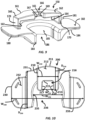
FIGS. 6-8 illustrate a backstop in a cross-sectional view, a perspective view, and a top view, respectively; -
FIG. 9 illustrates a further backstop in a perspective view; -
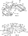
FIGS. 10 and11 illustrate another backstop in a top view and perspective view, respectively, andFIG. 12 illustrates a modification of the backstop ofFIGS. 10 and11 in perspective view; and -
FIGS. 13 and 14 illustrates yet another backstop in a perspective view and top view, respectively, andFIG. 15 illustrates a modification of the backstop ofFIGS. 13 and 14 in perspective view. -
FIG. 3 is a perspective view of aplunger rod 100.FIG. 4 is a side view of theplunger rod 100 disposed in asyringe barrel 140.FIG. 5 is a cross-sectional view of theplunger rod 100. - The
plunger rod 100 includes anelongated body 102 having acentral axis 104 extending between aproximal end 106 and adistal end 108. In one embodiment, thecentral axis 104 of theplunger rod 100 may coincide with a corresponding central axis of thesyringe barrel 140. Theelongated body 102 ofplunger rod 100 also includes a firstcurved end face 110, a secondcurved end face 112, and a joiningportion 114 which joins the firstcurved end face 110 to the secondcurved end face 112. The first and second curved end faces 110 and 112 may also be formed of straight line segments or a plurality of corresponding adjacent segments. In one example embodiment, each of the firstcurved end face 110, the secondcurved end face 112, and the joiningportion 114 extends between theproximal end 106 and thedistal end 108. At least the firstcurved end face 110 and the secondcurved end face 112 together may be inscribed by the circle defined by an outer perimeter 130 (shown inFIG. 5 ) ofelongated body 102. As shown, theouter perimeter 130 may be discontinuous. As will be discussed below, the geometry ofplunger rod 100 allowsplunger rod 100 to be manufactured with less material and molded with a shorter cycle time. - The
plunger rod 100 may optionally further include athumb press 126 located at theproximal end 106 of theelongated body 102 and a threadedcoupling portion 128 located at thedistal end 108 of theelongated body 102. Thethumb press 126 may include a portion that is wider than an interior dimension of thesyringe barrel 140 and provides a structure for a user to press when advancing theplunger rod 100 through thesyringe barrel 140. The circumference and diameter of the arcuateouter perimeter 130 may be less than the circumference and diameter of an arcuate outer perimeter of thethumb press 126. - A
stopper 127 may be threadably coupled to thecoupling portion 128. Alternatively, thestopper 127 may be clipped ontoplunger rod 100. In operation, a user may apply a force on thethumb press 126 and advance theplunger rod 100 andstopper 127 within thesyringe barrel 140. Thestopper 127 is sized relative tosyringe barrel 140 to provide sealing engagement with the interior surface of the sidewall ofsyringe barrel 140. It is noted herein that any suitable stopper may be employed with theplunger rod 100. - When assembled, the
elongated body 102 is at least partially disposed within thesyringe barrel 140. Thesyringe barrel 140 may be in the general form of an elongated cylindrical barrel, though thesyringe barrel 140 may be in other forms for containing a fluid for delivery. - The
syringe barrel 140 extends axially between adistal end 142 and aproximal end 144. Thebarrel 140 is configured to contain a medical fluid therein. Thebarrel 140 comprises an inner surface defining a hollow space in which thestopper 127 may be disposed. A cannula (e.g., needle) may be coupled to thedistal end 142 for injecting the medicinal fluid to a patient. The needle may be stacked on thedistal end 142 or may be coupled, such as by threading, to thedistal end 142 via an adaptor, which may be snap-fitted or glued to thedistal end 142. - The
syringe barrel 140 may be formed of glass, or may be injection molded from thermoplastic material such as polypropylene and polyethylene according to techniques known to those of ordinary skill in the art, though it is to be appreciated thatsyringe barrel 140 may be made from other suitable materials and according to other applicable techniques. - With continued reference to
FIGS. 3 and 5 , theplunger rod 100 may comprise a plurality of support ribs (twosupport ribs elongated body 102 betweenproximal end 106 anddistal end 108. Thesupport ribs central axis 104, and a plunger rod in accordance with the disclosed concept may include up to five ribs. - As best illustrated in
FIG. 5 , the joiningportion 114 includes anintermediate face 120, a first connecting face (e.g., without limitation, first angular face 122) extending fromintermediate face 120 to the firstcurved end face 110, and a second connecting face (e.g., without limitation, second angular face 124) extending from theintermediate face 120 to the secondcurved end face 112. - The angular faces 122 and 124 may be curved or straight. The joining
portion 114 at least partially defines the arcuateouter perimeter 130 of theelongated body 102, which may be concave facing towardcentral axis 104. In one example embodiment, theintermediate face 120 and the curved end faces 110, 112 may be inscribed by the circle delimited by theouter perimeter 130 of theelongated body 102 together therewith. Additionally, theintermediate face 120 may be curved or straight. Accordingly, it will be appreciated that the arcuateouter perimeter 130 may be discontinuous. - Furthermore, the first and second connecting faces may include the first and second angular faces 122, 124, respectively, with respect to the
intermediate face 120. More specifically, in one example embodiment, the first and second angular faces 122, 124 each extend from theintermediate face 120 at respective angles θ1, θ2 that are equal to or greater than 90 degrees with respect to theintermediate face 120. Preferably the angles θ1, θ2 are smaller than 120 degrees with respect to theintermediate face 120. Additionally, in one configuration, no portion of the firstcurved end face 110, the secondcurved end face 112, and/or the joiningportion 114 intersects the central axis 104 (depicted as a circle in order to represent an axis perpendicular with the page) ofelongated body 102. Accordingly, in this configuration, thecentral axis 104 of theplunger rod 100 is void of material. It is further noted that in certain embodiments, the firstcurved end face 110 and the secondcurved end face 112 do not intersect each other, i.e., the firstcurved end face 110 and the secondcurved end face 112 do not form a continuous exterior perimeter. - In operation, the geometry of
plunger rod 100 provides a number of advantages over known plunger rods such as theplunger rod 16 shown inFIGS. 2A and 2B . For example, by having a discontinuous arcuateouter perimeter 130, and having sections that do not intersect each other,elongated body 102 can advantageously be manufactured using less material than aconventional plunger rod 100. As previously discussed with reference toFIG. 2B , the firstplanar portion 21 and the secondplanar portion 23 intersect at thecentral region 25. It can readily be appreciated thatcentral region 25 has an undesirably large amount of material due to the intersection of the first and secondplanar portions plunger rod 16 due to the increased amount of material present within this region. Second, cycle times associated withmolding plunger rod 16 are relatively long, due to the time required for the largecentral region 25 to cool. - The
plunger rod 100 ofFIGS. 3-5 solves these problems by having a void at thecentral axis 104 which center area might otherwise generate large masses of material and associated costs can be reduced. In addition, theplunger rod 100 is able to resist breakage with better resistance to flexion (e.g., displacement away from central axis 104) during movement within the syringe barrel 140) thanconventional plunger rod 16, and are able to do so using significantly less material. Due to the increased resistance to breakage,plunger rods 100, unlikeplunger rod 16, may be manufactured out of different materials (e.g., without limitation, thermoplastic material such as a polycarbonate material, polypropylene, polystyrene, etc.). -
FIGS. 6-9 illustrate abackstop 150 useable with theplunger rod 100 as described herein. Thebackstop 150 includes atop plate 160 and abottom plate 180. At least oneconnector 170 extends between and connects thetop plate 160 and thebottom plate 180. - The
top plate 160 has anupper surface 162 and an oppositelower surface 164. In some embodiments, theupper surface 162 and thelower surface 164 may be substantially planar and may extend parallel to each other. - The
bottom plate 180 has anupper surface 182 and an oppositelower surface 184. Thebottom plate 180 is designed such that a user may grip theinjection device 101 and displace theplunger rod 100 within thebarrel 140. Thelower surface 184 of thebottom plate 180 may comprise one or more concave portions shaped for receiving an index and/or middle finger of the user to grip theinjection device 101 while a thumb of the user is placed on thethumb press 126 of theplunger rod 100. - The
lower surface 164 and theupper surface 182 of thebottom plate 180 are separated by a distance and define a space therebetween. The space is sized to retain theflange 148 of thesyringe barrel 140 therein. For instance, a height of the space may be substantially equal to a thickness of theflange 148 measured between theupper surface 145 and alower surface 143 of theflange 148. - The
top plate 160 includes afirst opening 166. Thefirst opening 166 is configured to receive theplunger rod 100 therein and allow theelongated body 102 of theplunger rod 100 to pass therethrough. Thefirst opening 166 extends fully through the top plate 160 (e.g., from theupper surface 162 to the lower surface 164). - At least three
planar surfaces first opening 166. First and secondplanar surfaces planar surface 165. The first and secondplanar surfaces planar surfaces planar surface 165. The first and secondplanar surfaces planar surfaces planar surface 165. - The first and second
planar surfaces plunger rod 100. Accordingly, theplunger rod 100 may pass through thefirst opening 166 as theplunger rod 100 is advanced within thesyringe barrel 140 when the user applies a force on thethumb press 126. - The
bottom plate 180 includes asecond opening 186. Thesecond opening 186 has a size and shape different from thefirst opening 166. Thesecond opening 186 is configured to retain thesyringe barrel 140 therein. Thesurface 185 defining the second opening is generally arcuate to correspond to the arcuate outer surface of thesyringe barrel 140. - In one arrangement, as illustrated in
FIGS. 6 and 7 , thebackstop 150 comprises oneconnector 170 extending along a portion of afirst side surface 161 of thetop plate 160 and along a portion of afirst side surface 181 of thebottom plate 180. Thefirst side surface 161 of thetop plate 160 is located opposite asecond side surface 163 of thetop plate 160 in which thefirst opening 166 is open such that theplunger rod 110 is receivable therein during assembly of the injection device. Thefirst side surface 181 of thebottom plate 180 is located opposite asecond side surface 183 of thebottom plate 180 in which thesecond opening 186 is open such that thesyringe barrel 101 is receivable therein. - The
connector 170 extends generally vertically between the top andbottom plates bottom plates flange 148 of thesyringe barrel 140 is unbounded by thebackstop 150. - In another arrangement, as illustrated in
FIG. 8 , thebackstop 150 comprises two opposingconnectors 170. Each of the twoconnectors 170 extends from thefirst side surface 161 of thetop plate 160 and thefirst side surface 181 of thebottom plate 180 toward thesecond side surface 163 of thetop plate 160 and thesecond side surface 183 of thebottom plate 180. - The provision of two opposing
connectors 170 results in an increase in the width W160 of thetop plate 160 while maintaining the depth D160 relative to thetop plate 160 having asingle connector 170. The two opposingconnectors 170 extend along two sides of the top andbottom plates flange 148 of thesyringe barrel 140 is unbounded by thebackstop 150. - In either embodiment, the connector(s) 170 extend(s) about a minority of the periphery of the space in which the
flange 148 of thesyringe barrel 140 is received. This limits the cost and time of manufacturing by reducing material usage. - The
top plate 160 is designed to prevent thestopper 127 coupled to thecoupling portion 128 of theplunger rod 100 from being removed from thesyringe barrel 140 while allowing theelongated body 102 to pass through thefirst opening 126 when theplunger rod 100, thesyringe barrel 140, and thebackstop 150 are assembled together. Thetop plate 160 has a width W160 and a depth D160 sufficient to provide an abutment for theupper surface 145 of theflange 148. - The
top plate 160 is dimensioned so as to minimize the amount of material used in its construction. The width W160 of thetop plate 160 is less than a width W180 of thebottom plate 180. The depth D160 of thetop plate 160 is less than a depth Disc of thebottom plate 180. Thus, a volume of thetop plate 160 is less than a volume of thebottom plate 180. - The depth D160 of the
top plate 160 is selected to avoid contact between thesupport ribs top plate 160 such that theplunger rod 100 passes through thefirst opening 166 when the user applies a force on thethumb press 126. - A width W166 of the
first opening 166 of thetop plate 160 may be less than a width Wise of thesecond opening 186 of thebottom plate 180. The width W166 of thefirst opening 166 is selected to be less than a width W108 of thedistal end 108 of theplunger rod 100 to prevent withdrawal of thedistal end 108 of theplunger rod 100 from thesyringe barrel 140. The W166 is selected to be greater than the distance between the angular faces 122, 124 of the joiningportion 114 such that theplunger rod 100 passes through thefirst opening 166 when the user applies a force on thethumb press 126. -
FIGS. 10-12 illustrate anotherbackstop 200 useable with theplunger rod 100 as described herein. Thebackstop 200 includes atop plate 210, abottom plate 230, and at least oneconnector 220 extending therebetween. Thebackstop 200 is substantially similar to thebackstop 160 except that the overall shape of thebottom plate 230 and thetop plate 210 are different from thetop plate 160 andbottom plate 170. - Like the
top plate 160, thetop plate 210 has anupper surface 212 and an oppositelower surface 214, which may be substantially planar and may extend parallel to each other. - The
bottom plate 230 has anupper surface 212 and an oppositelower surface 214. Thebottom plate 230 is designed such that a user may grip theinjection device 101 and displace theplunger rod 100 within thebarrel 140. Thelower surface 234 of thebottom plate 230 is generally planar and is configured for an index and/or middle finger of the user to rest therein in order to grip theinjection device 101 while a thumb of the user is placed on thethumb press 126 of theplunger rod 100. - The
lower surface 234 and theupper surface 232 of thebottom plate 230 are separated by a distance and define a space therebetween, which space is sized to retain theflange 148 of thesyringe barrel 140 therein as previously described. - The
top plate 210 includes afirst opening 216. Like thetop plate 160, at least threeplanar surfaces first opening 166. The first and secondplanar surfaces planar surfaces planar surface 165. - The
bottom plate 230 includes asecond opening 236, which is configured to retain thesyringe barrel 140 therein. In one arrangement, as illustrated inFIGS. 10 and11 , thebackstop 200 comprises oneconnector 220 extending along a portion of afirst side surface 211 of thetop plate 210 and along a portion of afirst side surface 231 of thebottom plate 230. Thefirst side surface 211 of thetop plate 210 being opposite asecond side surface 213 of thetop plate 210 in which thefirst opening 216 is open such that theplunger rod 110 is receivable therein during assembly of the injection device. Thefirst side surface 231 of thebottom plate 230 being opposite asecond side surface 233 of thebottom plate 230 in which thesecond opening 236 is open such that thesyringe barrel 101 is receivable therein. - In another arrangement, as illustrated in
FIG. 12 , thebackstop 200 comprises two opposingconnectors 220. Each of the twoconnectors 220 extends from thefirst side surface 211 of thetop plate 210 and thefirst side surface 231 of thebottom plate 230 toward thesecond side surface 213 of thetop plate 210 and thesecond side surface 233 of thebottom plate 230. - In either embodiment, the connector(s) 220 extend(s) generally vertically between the top and
bottom plates bottom plates flange 148 of thesyringe barrel 140 is unbounded by thebackstop 200. This limits the cost and time of manufacturing by reducing material usage. - The provision of two opposing
connectors 220 results in an increase in the width W210 of thetop plate 210 while maintaining the depth D210 relative to thetop plate 210 having asingle connector 220. The two opposingconnectors 220 extend along two sides of the top andbottom plates flange 148 of thesyringe barrel 140 is unbounded by thebackstop 200. - A size and shape of the
first opening 216 of thetop plate 210 is different from a shape of thesecond opening 236 of thebottom plate 230. As was explained with reference to thebackstop 150, thefirst opening 216 is configured to receive theplunger rod 100 therein and allow theelongated body 102 of theplunger rod 100 to pass therethrough. Thefirst opening 216 extends fully through the top plate 210 (e.g., from theupper surface 212 to the lower surface 214). - The
top plate 210 is designed to prevent thestopper 127 coupled to thecoupling portion 128 of theplunger rod 100 from being removed from thesyringe barrel 140 when theplunger rod 100, thesyringe barrel 140, and thebackstop 200 are assembled together. Thetop plate 210 has a width W210 and a depth D210 sufficient to provide an abutment for theupper surface 145 of theflange 148 so as to maintain thesyringe barrel 140 within thebackstop 200. - The
top plate 210 is dimensioned so as to minimize the amount of material used in its construction. The width W210 of thetop plate 210 is less than a width W230 of thebottom plate 230. Further, the depth D210 of thetop plate 210 is less than a depth D230 of thebottom plate 230. Thus, a volume of thetop plate 210 is less than a volume of thebottom plate 230. - The depth D210 of the
top plate 210 is selected to avoid contact between thesupport ribs top plate 210 such that theplunger rod 100 passes through thefirst opening 216 when the user applies a force on thethumb press 126. - A width W216 of the
first opening 216 of thetop plate 210 may be less than a width W236 of thesecond opening 236 of thebottom plate 230. The width W216 of thefirst opening 216 is selected to be less than a width W108 of thedistal end 108 of theplunger rod 100 to prevent withdrawal of thedistal end 108 of theplunger rod 100 from thesyringe barrel 140. The W216 is selected to be greater than the distance between the angular faces 122, 124 of the joiningportion 114 such that theplunger rod 100 passes through thefirst opening 216 when the user applies a force on thethumb press 126. -
FIGS. 13-15 illustrate a further embodiment of abackstop 250 useable with theplunger rod 100 as described herein. Thebackstop 250 includes atop plate 260, abottom plate 280, and at least oneconnector 270 extending therebetween. Thebackstop 250 is substantially similar to thebackstop 160 except that the overall shape of thebottom plate 280 and thetop plate 260 are different from thetop plate 160 andbottom plate 170. - Like the
top plate 160, thetop plate 260 has anupper surface 262 and an oppositelower surface 264, which may be substantially planar and may extend parallel to each other. - The
bottom plate 280 has anupper surface 282 and an oppositelower surface 284. Thebottom plate 280 is designed such that a user may grip theinjection device 101 and displace theplunger rod 100 within thebarrel 140. Thelower surface 284 of thebottom plate 280 is generally planar and is configured for an index and/or middle finger of the user to rest therein in order to grip theinjection device 101 while a thumb of the user is placed on thethumb press 126 of theplunger rod 100. - The
lower surface 284 and theupper surface 282 of thebottom plate 280 are separated by a distance and define a space therebetween, which space is sized to retain theflange 148 of thesyringe barrel 140 therein as previously described. - The
top plate 260 includes afirst opening 266. Like thetop plate 160, at least threeplanar surfaces first opening 266. The first and secondplanar surfaces planar surfaces planar surface 265. - The
bottom plate 280 includes asecond opening 286, which is configured to retain thesyringe barrel 140 therein. In one arrangement, as illustrated inFIGS. 10 and11 , thebackstop 250 comprises oneconnector 270 extending along a portion of afirst side surface 261 of thetop plate 260 and along a portion of afirst side surface 281 of thebottom plate 280. Thefirst side surface 261 of thetop plate 260 being opposite asecond side surface 263 of thetop plate 260 in which thefirst opening 266 is open such that theplunger rod 110 is receivable therein during assembly of the injection device ###. Thefirst side surface 281 of thebottom plate 280 being opposite asecond side surface 283 of thebottom plate 280 in which thesecond opening 286 is open such that thesyringe barrel 101 is receivable therein. - In another arrangement, as illustrated in
FIG. 12 , thebackstop 250 comprises two opposingconnectors 270. Each of the twoconnectors 270 extends from thefirst side surface 261 of thetop plate 260 and thefirst side surface 281 of thebottom plate 280 toward thesecond side surface 263 of thetop plate 260 and thesecond side surface 283 of thebottom plate 280. - The provision of two opposing
connectors 270 results in an increase in the width W260 of thetop plate 260 while maintaining the depth D260 relative to thetop plate 260 having asingle connector 270. The two opposingconnectors 270 extend along two sides of the top andbottom plates flange 148 of thesyringe barrel 140 is unbounded by thebackstop 250. - In either embodiment, the connector(s) 270 extend(s) generally vertically between the top and
bottom plates bottom plates flange 148 of thesyringe barrel 140 is unbounded by thebackstop 250. This limits the cost and time of manufacturing by reducing material usage. - A size and shape of the
first opening 266 of thetop plate 260 is different from a shape of thesecond opening 286 of thebottom plate 280. Thefirst opening 266 is configured to receive theplunger rod 100 therein and allow theelongated body 102 of theplunger rod 100 to pass therethrough. Thefirst opening 266 extends fully through the top plate 260 (e.g., from theupper surface 262 to the lower surface 264). - The
top plate 260 is designed to prevent thestopper 127 coupled to thecoupling portion 128 of theplunger rod 100 from being removed from thesyringe barrel 140 when theplunger rod 100, thesyringe barrel 140, and thebackstop 250 are assembled together. Thetop plate 260 has a width W260 and a depth D260 sufficient to provide an abutment for theupper surface 145 of theflange 148. - The
top plate 260 is dimensioned so as to minimize the amount of material used in its construction. The width W260 of thetop plate 260 is less than a width W280 of thebottom plate 280. The depth D260 of thetop plate 260 is less than a depth D280 of thebottom plate 280. Thus, a volume of thetop plate 260 is less than a volume of thebottom plate 280. - A width W266 of the
first opening 266 of thetop plate 260 may be less than a width W286 of thesecond opening 286 of thebottom plate 280. The width W266 of thefirst opening 266 is selected to be less than a width W108 of thedistal end 108 of theplunger rod 100 to prevent withdrawal of thedistal end 108 of theplunger rod 100 from thesyringe barrel 140. The W266 is selected to be greater than the distance between the angular faces 122, 124 of the joiningportion 114 such that theplunger rod 100 passes through thefirst opening 266 when the user applies a force on thethumb press 126.
Claims (12)
- A backstop device (150, 200, 250) for maintaining a distal end (108) of a plunger rod (110) in a syringe barrel (140), the backstop device (150, 200, 250) comprising:a top plate (160, 210, 260) defining a first opening (166, 216, 266) that is configured to receive a plunger rod (110) having an elongated body (102) having a joining portion (114) joining a first curved end face (110) to a second curved end face (112) therein;a bottom plate (180, 230, 280) defining a second opening (186, 236, 286) that is configured to receive the syringe barrel (140) therein, wherein the first opening (166, 216, 266) has a shape different from a shape of the second opening (186, 236, 286); andat least one connector (170, 220, 270) extending between the top plate (160, 210, 260) and the bottom plate (180, 230, 280).
- The backstop device (150, 200, 250) of claim 1, wherein the first opening (166, 216, 266) of the top plate (160, 210, 260) is defined by a first planar surface (167, 217, 267), a second planar surface (169, 219, 269), and a third planar surface (165, 215, 265), the first planar surface and second planar surface being located proximate to opposite ends of the third planar surface (165) and extending away from the third planar surface in a parallel manner or in a diverging manner.
- The backstop device (150, 200, 250) of any of claims 1-2, wherein a maximum depth (D160, D210, D260) of the top plate (160, 210, 260) is less than a maximum depth (D180, D230, D280) of the bottom plate (180, 230, 280).
- The backstop device (150, 200, 250) of any of claims 1-3, wherein a maximum width (W160, W210, W260) of the top plate (160, 210, 260) is less than a maximum width (W180, W230, W280) of the bottom plate (180, 230, 280).
- The backstop device (150, 200, 250) of any of claims 1-4, wherein the second opening (186, 236, 286) of the bottom plate (180, 230, 280) is at least partially defined by an arcuate surface (185, 235, 285), a curvature of the arcuate surface (185, 235, 285) corresponding to a curvature of an exterior surface of the syringe barrel (140) receivable therein.
- The backstop device (150, 200, 250) of any of claims 1-5, wherein an upper surface (162, 212, 262) and a lower surface (164, 214, 264) of the top plate (160, 210, 260) extend substantially parallel to each other.
- The backstop device (150, 200, 250) of any of claims 1-6, wherein the at least one connector (170, 220, 270) of the backstop device (150, 200, 250) extends along a portion of a first side surface (161, 211, 261) of the top plate (160, 210, 260) and along a portion of a first side surface (181, 231, 281) of the bottom plate (180, 230, 280), the first side surface (161, 211, 261) of the top plate (160, 210, 260) being opposite a second side surface (163, 213, 263) of the top plate (160, 210, 260) in which the first opening (166, 216, 266) is open such that the plunger rod (110) is receivable therein, the first side surface (181, 231, 281) of the bottom plate (180, 230, 280) being opposite a second side surface (183, 233, 283) of the bottom plate (180, 230, 280) in which the second opening (186, 236, 286) is open such that the syringe barrel (140) is receivable therein.
- The backstop device (150, 200, 250) of any of claims 1-6, wherein the at least one connector (170, 220, 270) of the backstop device (150, 200, 250) comprises two opposing connectors (170, 220, 270), each of the two connectors (170, 220, 270) extending from a first side surface (161, 211, 261) of the top plate (160, 210, 260) and a first side surface (181, 231, 281) of the bottom plate (180, 230, 280) toward a second side surface (163, 213, 263) of the top plate (160, 210, 260) and a second side surface (183, 233, 283) of the bottom plate (180, 230, 280).
- The backstop device (150, 200, 250) of any of claims 1-8, wherein a volume of the top plate (160) is less than a volume of the bottom plate (180, 230, 280).
- An injection device (101) comprising:a syringe barrel (140);a plunger rod (110) comprising an elongated body (102) extending along a central axis (104) between a proximal end (106) and a distal end (108), the body having a joining portion (114) joining a first curved end face (110) to a second curved end face (112), each of the first curved end face (110), the second curved end face (112), and the joining portion (114) extending between the proximal end (106) and the distal end (108), wherein the first curved end face (110) and the second curved end face (112) together define a discontinuous arcuate outer perimeter of the elongated body (102); andthe backstop device (150, 200, 250) according to any of claims 1-9.
- The injection device (101) of claim 10, wherein a distance (W166, W216, W266) between a first planar surface (167, 217, 267) and a second planar surface (169, 219, 269) of the first opening (166, 216, 266) of the top plate (160, 210, 260) is less than a diameter of the distal end (108) of the plunger rod (110).
- The injection device (101) of claims 10 or 11, wherein the bottom plate (180, 230, 280) is separated from the top plate (160, 210, 260) by a distance such that, when the backstop device (150, 200, 250) is coupled to the syringe barrel (140), a lower surface (164) of the top plate (160, 210, 260) and an upper surface (182, 232, 282) of the bottom plate (180, 230, 280) contact an upper surface (157) and a lower surface (159) of a flange (158) of the syringe barrel (140), respectively.
Priority Applications (3)
| Application Number | Priority Date | Filing Date | Title |
|---|---|---|---|
| EP23315160.4A EP4458390A1 (en) | 2023-05-04 | 2023-05-04 | Backstop device for an injection device |
| CN202480028980.8A CN121057597A (en) | 2023-05-04 | 2024-05-03 | Stopper device for an injection device |
| PCT/EP2024/062321 WO2024227937A1 (en) | 2023-05-04 | 2024-05-03 | Backstop device for an injection device |
Applications Claiming Priority (1)
| Application Number | Priority Date | Filing Date | Title |
|---|---|---|---|
| EP23315160.4A EP4458390A1 (en) | 2023-05-04 | 2023-05-04 | Backstop device for an injection device |
Publications (1)
| Publication Number | Publication Date |
|---|---|
| EP4458390A1 true EP4458390A1 (en) | 2024-11-06 |
Family
ID=86605124
Family Applications (1)
| Application Number | Title | Priority Date | Filing Date |
|---|---|---|---|
| EP23315160.4A Pending EP4458390A1 (en) | 2023-05-04 | 2023-05-04 | Backstop device for an injection device |
Country Status (3)
| Country | Link |
|---|---|
| EP (1) | EP4458390A1 (en) |
| CN (1) | CN121057597A (en) |
| WO (1) | WO2024227937A1 (en) |
Citations (5)
| Publication number | Priority date | Publication date | Assignee | Title |
|---|---|---|---|---|
| FR360751A (en) * | 1905-12-21 | 1906-05-03 | Herman Adolphe Wulfing Luer | Aseptic syringe |
| US5667495A (en) | 1995-04-21 | 1997-09-16 | Becton Dickinson France S.A. | Backstop device for a syringe |
| FR2876034A1 (en) * | 2003-11-14 | 2006-04-07 | Plastic Omnium Cie | SAFETY ASSEMBLY FOR EQUIPPING A SYRINGE AND SYRINGE ASSEMBLY |
| WO2019149869A2 (en) * | 2018-02-02 | 2019-08-08 | F. Hoffmann-La Roche Ag | Prefilled syringe and method of sterilizing a prefilled syringe |
| WO2021180824A1 (en) * | 2020-03-11 | 2021-09-16 | Becton Dickinson France | Plunger rod and syringe including same |
-
2023
- 2023-05-04 EP EP23315160.4A patent/EP4458390A1/en active Pending
-
2024
- 2024-05-03 CN CN202480028980.8A patent/CN121057597A/en active Pending
- 2024-05-03 WO PCT/EP2024/062321 patent/WO2024227937A1/en not_active Ceased
Patent Citations (5)
| Publication number | Priority date | Publication date | Assignee | Title |
|---|---|---|---|---|
| FR360751A (en) * | 1905-12-21 | 1906-05-03 | Herman Adolphe Wulfing Luer | Aseptic syringe |
| US5667495A (en) | 1995-04-21 | 1997-09-16 | Becton Dickinson France S.A. | Backstop device for a syringe |
| FR2876034A1 (en) * | 2003-11-14 | 2006-04-07 | Plastic Omnium Cie | SAFETY ASSEMBLY FOR EQUIPPING A SYRINGE AND SYRINGE ASSEMBLY |
| WO2019149869A2 (en) * | 2018-02-02 | 2019-08-08 | F. Hoffmann-La Roche Ag | Prefilled syringe and method of sterilizing a prefilled syringe |
| WO2021180824A1 (en) * | 2020-03-11 | 2021-09-16 | Becton Dickinson France | Plunger rod and syringe including same |
Also Published As
| Publication number | Publication date |
|---|---|
| WO2024227937A1 (en) | 2024-11-07 |
| CN121057597A (en) | 2025-12-02 |
Similar Documents
| Publication | Publication Date | Title |
|---|---|---|
| US10926044B2 (en) | Pen needle hub having increased contact area | |
| KR102385255B1 (en) | Precise and precise microliter dosing syringes | |
| US8043249B2 (en) | Fixing device for injection needles | |
| EP2436408B1 (en) | Syringe assembly and package for distribution of same | |
| US6296625B1 (en) | Finger brace for hypodermic syringe | |
| US7556615B2 (en) | Microneedle-based pen device for drug delivery and method for using same | |
| DK2601991T3 (en) | medicine Injection | |
| US10702653B2 (en) | Syringe holder and pharmaceutical liquid administration set | |
| US9808583B2 (en) | Percutaneous medication device and needle formation used for the device | |
| CN1308550A (en) | Medication delivery device and catridge assembly for use in the same | |
| WO2021201075A1 (en) | Medical syringe plunger and medical finger grip | |
| US7713245B2 (en) | Plunger for retracting needle syringe | |
| EP4458390A1 (en) | Backstop device for an injection device | |
| US11419985B2 (en) | Medication injection device | |
| US6030367A (en) | Plunger rod | |
| US12605510B2 (en) | Plunger rod and syringe including same | |
| CN222195644U (en) | Dual chamber injector assembly and automatic injection pen | |
| KR20180031575A (en) | Injection Needle | |
| JP7459062B2 (en) | Syringe assembly and adapter parts | |
| JP2026514177A (en) | Backstop device for injection equipment | |
| AU2021235045B2 (en) | Plunger rod and syringe including same |
Legal Events
| Date | Code | Title | Description |
|---|---|---|---|
| PUAI | Public reference made under article 153(3) epc to a published international application that has entered the european phase |
Free format text: ORIGINAL CODE: 0009012 |
|
| STAA | Information on the status of an ep patent application or granted ep patent |
Free format text: STATUS: THE APPLICATION HAS BEEN PUBLISHED |
|
| AK | Designated contracting states |
Kind code of ref document: A1 Designated state(s): AL AT BE BG CH CY CZ DE DK EE ES FI FR GB GR HR HU IE IS IT LI LT LU LV MC ME MK MT NL NO PL PT RO RS SE SI SK SM TR |
|
| STAA | Information on the status of an ep patent application or granted ep patent |
Free format text: STATUS: REQUEST FOR EXAMINATION WAS MADE |
|
| 17P | Request for examination filed |
Effective date: 20250505 |