EP4458307A1 - Forceps device - Google Patents
Forceps device Download PDFInfo
- Publication number
- EP4458307A1 EP4458307A1 EP22920317.9A EP22920317A EP4458307A1 EP 4458307 A1 EP4458307 A1 EP 4458307A1 EP 22920317 A EP22920317 A EP 22920317A EP 4458307 A1 EP4458307 A1 EP 4458307A1
- Authority
- EP
- European Patent Office
- Prior art keywords
- grasping
- guide pulleys
- support
- rotating shaft
- forceps device
- Prior art date
- Legal status (The legal status is an assumption and is not a legal conclusion. Google has not performed a legal analysis and makes no representation as to the accuracy of the status listed.)
- Granted
Links
Images






Classifications
-
- A—HUMAN NECESSITIES
- A61—MEDICAL OR VETERINARY SCIENCE; HYGIENE
- A61B—DIAGNOSIS; SURGERY; IDENTIFICATION
- A61B17/00—Surgical instruments, devices or methods
- A61B17/28—Surgical forceps
- A61B17/2812—Surgical forceps with a single pivotal connection
-
- A—HUMAN NECESSITIES
- A61—MEDICAL OR VETERINARY SCIENCE; HYGIENE
- A61B—DIAGNOSIS; SURGERY; IDENTIFICATION
- A61B34/00—Computer-aided surgery; Manipulators or robots specially adapted for use in surgery
- A61B34/70—Manipulators specially adapted for use in surgery
- A61B34/71—Manipulators operated by drive cable mechanisms
-
- A—HUMAN NECESSITIES
- A61—MEDICAL OR VETERINARY SCIENCE; HYGIENE
- A61B—DIAGNOSIS; SURGERY; IDENTIFICATION
- A61B34/00—Computer-aided surgery; Manipulators or robots specially adapted for use in surgery
- A61B34/30—Surgical robots
- A61B2034/305—Details of wrist mechanisms at distal ends of robotic arms
-
- A—HUMAN NECESSITIES
- A61—MEDICAL OR VETERINARY SCIENCE; HYGIENE
- A61B—DIAGNOSIS; SURGERY; IDENTIFICATION
- A61B34/00—Computer-aided surgery; Manipulators or robots specially adapted for use in surgery
- A61B34/70—Manipulators specially adapted for use in surgery
- A61B34/71—Manipulators operated by drive cable mechanisms
- A61B2034/715—Cable tensioning mechanisms for removing slack
-
- A—HUMAN NECESSITIES
- A61—MEDICAL OR VETERINARY SCIENCE; HYGIENE
- A61B—DIAGNOSIS; SURGERY; IDENTIFICATION
- A61B34/00—Computer-aided surgery; Manipulators or robots specially adapted for use in surgery
- A61B34/30—Surgical robots
Definitions
- the present invention relates to a forceps device used for a manipulator of a surgical robot.
- Patent Literature 1 teaches a forceps device including a first rotating shaft (118) that turnably supports a support (107) holding a grasping part (101, 104), a base member (120) that holds the first rotating shaft, a plurality of first guide pulleys (111, 112, 113, 114) arranged coaxially with the first rotating shaft, a plurality of grasping-portion wires (102, 103, 105, 106) that transmits driving forces to move the grasping part, the grasping-portion wires running between the plurality of first guide pulleys and the grasping part without other pulleys, and a second rotating shaft (119) that turnably supports second guide pulleys located upstream of the first guide pulleys.
- Patent Literature 1 CN 107928792 A
- the first guide pulleys and the second guide pulleys arranged in parallel with the central axis of the support.
- the first guide pulleys and the second guide pulleys need to be close to each other. If the first guide pulleys and the second guide pulleys are close to each other, however, the radii of curvature of the wound grasping-portion wires are small. When the grasping-portion wires in this state are repeatedly pulled, the durability of the grasping-portion wires may significantly lower.
- the tensions of the grasping-portion wires are increased so as to increase the grasping force of the grasping part of the aforementioned forceps device, the frictional force between the first rotating shaft and the support increases, which lowers the controllability of the bending movement of the support including the grasping part about the first rotating shaft.
- the present invention has been made in view of the aforementioned circumstances, and an exemplary object thereof is to provide a novel technology for improving the durability of wires or improving the controllability of the operation of the forceps device.
- a forceps device includes: a grasping part; a support that holds the grasping part; a first rotating shaft that turnably supports the support; a base member that holds the first rotating shaft; a plurality of grasping-portion wires that transmit driving forces to move the grasping part; first guide pulleys arranged coaxially with the first rotating shaft, the grasping-portion wires running over the first guide pulleys; and second guide pulleys arranged upstream of the first guide pulleys, the grasping-portion wires running over the second guide pulleys.
- the second guide pulleys are: (i) shifted toward one side relative to immediately below the first guide pulleys when the first rotating shaft is viewed in front in an axial direction in a state in which a leading end of a grasping part points upward; and (ii) arranged so that winding angles ⁇ of the grasping-portion wires around the first guide pulleys are 65° or larger at a neutral position at which the support is not turned to left or right.
- comfortable operation control can be achieved with the turning angle of the support, which holds the grasping part, being at least within a range of ⁇ 65°.
- the winding angles ⁇ may be 89° or larger. This enables comfortable operation control with the turning angle of the support, which holds the grasping part, being at least within a range of ⁇ 89°.
- the forceps device may further include third guide pulleys arranged upstream of the second guide pulleys, the grasping-portion wires running over the third guide pulleys.
- the third guide pulleys may be: (i) shifted toward one side relative to immediately below the first guide pulleys when the first rotating shaft is viewed in front in the axial direction in the state in which the leading end of the grasping part points upward; and (ii) shifted toward the other side relative to immediately below the second guide pulleys when the first rotating shaft is viewed in front in the axial direction in the state in which the leading end of the grasping part points upward.
- the third guide pulleys may be a pair of guide pulleys arranged on respective sides of an inner wall of the base member, and the pair of third guide pulleys may be rotatably supported by different support shafts, respectively, held by the base member. This enables the third guide pulleys and the second guide pulleys to be arranged on the same side (right side or left side) when the first guide pulleys are viewed from the front.
- the base member may be a cylindrical part having an outer diameter of 7 to 9 mm
- the first guide pulleys may have a diameter of 3.0 to 3.6 mm
- the second guide pulleys may have a diameter of 3.0 to 3.6 mm
- the third guide pulleys may have a diameter of 3.0 to 3.6 mm.
- the durability of wires or the controllability of the operation of the forceps device is improved.
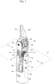
- FIG. 1 is a perspective view of a forceps device according to an embodiment.
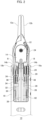
- FIG. 2 is a front view of the forceps device of FIG. 1 as viewed in a direction A.
- FIG. 3 is a side view of the forceps device of FIG. 1 as viewed in a direction B.
- FIG. 4 is a side view of the forceps device of FIG. 1 as viewed in a direction C.
- the forceps device 10 illustrated in the drawings includes a pair of grasping portions 12a and 12b, a support 14 that holds the pair of grasping portions 12a and 12b, a first rotating shaft 16 that turnably supports the support 14, a base member 18 that holds the first rotating shaft 16, four guide pulleys 20 arranged coaxially with the first rotating shaft 16, a second rotating shaft 22 that turnably supports the pair of grasping portions 12a and 12b and is held by the support 14, four jaw pulleys 24 supported coaxially with the second rotating shaft 22, four wires 26, 28, 30 and 32 running over the four guide pulleys 20 and the four jaw pulleys 24, and wires 38 and 40 for turning the support 14 about the first rotating shaft 16.
- FIG. 5 is a cross-sectional view of the forceps device 10 illustrated in FIG. 3 along D-D.
- the guide pulleys 20 are rotatably supported by the first rotating shaft 16 inserted in a bearing 15 mounted on the support 14.
- the guide pulleys 20 according to the embodiment are arranged in such a manner that two guide pulleys 20 adjacent to each other are present on respective sides with respect to the support 14.
- the base member 18 As illustrated in FIG. 2 and FIG. 5 , the base member 18 according to the embodiment includes a pair of arms 18a and 18b that hold respective ends of the first rotating shaft 16, and third rotating shafts 36 that are held by the pair of arms 18a and 18b, respectively, and rotatably support four guide pulleys 34 located upstream of the guide pulleys 20.
- a third rotating shaft 36 according to the embodiment is provided on each of the pair of arms 18a and 18b.
- the two rotating shafts 36 are arranged with their axial directions being parallel to each other but not being aligned with each other.
- the arms 18a and 18b each have a base part 18c holding the third rotating shaft 36, and a distal end part 18d that holds the first rotating shaft 16 and that is thinner than the base part 18c.
- the distance between the distal end parts 18d is larger than the distance between the base parts 18c.
- the circumferential width W1 of the distal end part 18d of the arm 18a (the arm 18b) is smaller than the circumferential width W2 of the base part 18c thereof.
- a U-shaped recess is formed at the distal end part 18d at which interference with a wire needs to be addressed, and the circumferential width of the distal end part 18d is made larger than the circumferential width of the base part 18c, which minimizes deterioration of the stiffness of the arm.
- the jaw pulleys 24 according to the embodiment have an outer diameter G1, which is larger than the distance between the base parts 18c of the pair of arms 18a and 18b.
- the jaw pulleys 24 having a large outer diameter relative to the inner diameter of the cylindrical base member 18 may be used.
- FIG. 6 is a perspective view of the support according to the embodiment.
- FIG. 7 is a front view of the support according to the embodiment.
- FIG. 8 is a side view of the support according to the embodiment.
- the forceps device 10 according to the embodiment includes the pair of grasping portions 12a and 12b, the support 14 that holds the pair of grasping portions 12a and 12b, the first rotating shaft 16 that turnably supports the support 14, the base member 18 that holds the first rotating shaft 16, and a plurality of guide pulleys 20 arranged coaxially with the first rotating shaft 16.
- the support 14 has a circular through-hole 14a in which the bearing 15, which is a shaft bearing, is mounted.
- the first rotating shaft 16 which rotatably supports the support 14, is inserted into the bearing 15 mounted on the support 14.
- the guide pulleys 20 are rotatably supported by the outer circumference of the first rotating shaft 16. Note that each rotating shaft is not limited to a shaft that rotates by itself, but may be any shaft that is the center of rotation of a member supported thereby, and may be a shaft fixed to another member.
- the support 14 in a state in which a plurality of guide pulleys 20 are supported by the outer circumference of the first rotating shaft 16 is held by the base member 18 with the first rotating shaft 16 therebetween.
- This configuration facilitates improvement in the easiness of assembly as compared with a case where the support 14 is held directly by the base member 18.
- the base member 18 of the embodiment has the pair of arms 18a and 18b facing each other.
- the first rotating shaft 16 is firmly fixed in such a manner that the axial ends thereof are press-fitted to the pair of arms 18a and 18b.
- Each of the wires 26, 28, 30 and 32 transmits a driving force to the grasping portion 12a or the grasping portion 12b to move the grasping portion 12a or the grasping portion 12b.
- the wire 26 and the wire 32 run over the jaw pulleys 24 for the grasping portion 12b, and the grasping portion 12b moves in an opening direction when the wire 26 is pulled and moves in a closing direction when the wire 32 is pulled.
- the wire 28 and the wire 30 run over the jaw pulleys 24 for the grasping portion 12a, and the grasping portion 12a moves in a closing direction when the wire 28 is pulled and moves in an opening direction when the wire 30 is pulled.
- each of the four guide pulleys 20 has a corresponding one of the wires 26, 28, 30 and 32 placed thereover. As illustrated in FIG. 2 , each of the wires 26, 28, 30 and 32 passes between the corresponding ones of the guide pulleys 20 and guide pulleys 34 and runs over the corresponding one of the guide pulleys 20 from a lower side thereof (a side opposite the grasping portion 12a or 12b with respect to the first rotating shaft 16).
- a support pulley 42 over which the wires 38 and 40 for transmitting a driving force for turning the support about the first rotating shaft 16 run, is formed integrally with part of the support 14.
- the support pulley 42 is arranged coaxially with the first rotating shaft 16.
- the force applied to the inner circumference of the through-hole of the support 14 for supporting the second rotating shaft 22 is then transmitted to the circular through-hole 14a in which the bearing 15 is mounted, and the support 14 is thus pressed toward the first rotating shaft 16.
- a normal force received by the support 14 from the first rotating shaft 16 is generated, which contributes to an increase in frictional force.
- the bearing is provided between the support 14 and the first rotating shaft 16, which reduces the frictional force between the first rotating shaft 16 and the support 14.
- the bearing 15 is a rolling bearing
- the frictional force between the first rotating shaft 16 and the support 14 can further be reduced. Consequently, the movement of the grasping portions 12a and 12b becomes smoother, and the controllability of the forceps device 10 improves.
- the bearing may be a plain bearing.
- the bearing 15 according to the embodiment may have a diameter of 3.6 to 4.5 mm, and the guide pulleys 20 may have a diameter of 3.0 to 3.6 mm.
- the bearing 15 may have a diameter larger than that of the guide pulleys 20.
- FIG. 9 is a perspective view illustrating a state in which a pair of jaw parts facing each other are to be fitted according to the embodiment.
- Jaw parts 50A and 50B illustrated in FIG. 9 are parts having substantially the same shapes as each other.
- the jaw parts 50A and 50B have the grasping portion 12a and the grasping portion 12b, respectively, which move relative to each other to grasp an object.
- the grasping portion 12a is continuous with a jaw pulley 24a (first grasping portion pulley) and a jaw pulley 24b (second grasping portion pulley), which are formed in a bifurcated shape, and the grasping portion 12a and the jaw pulleys 24a and 24b integrally constitute the jaw part 50A.
- the grasping portion 12b is continuous with a jaw pulley 24c (third grasping portion pulley) and a jaw pulley 24d (fourth grasping portion pulley), which are formed in a bifurcated shape, and the grasping portion 12b and the jaw pulleys 24c and 24d integrally constitute the jaw part 50B.
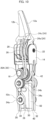
- FIG. 10 is a perspective view of the forceps device 10 illustrated in FIG. 1 as viewed in a direction H1.
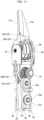
- FIG. 11 is a perspective view of the forceps device 10 illustrated in FIG. 1 as viewed in a direction H2.
- FIG. 12 is a perspective view of the forceps device 10 illustrated in FIG. 1 as viewed in a direction H3.
- FIG. 13 is a perspective view of the forceps device 10 illustrated in FIG. 1 as viewed in a direction opposite the direction H2.
- the directions H1 to H3 are directions within a horizontal plane H including the first rotating shaft 16.
- the base member 18 is not illustrated in FIGS. 10 to 13 .
- the jaw pulley 24a, the jaw pulley 24c, the jaw pulley 24b, and the jaw pulley 24d are rotatably supported in this order by the second rotating shaft 22.
- the guide pulley 20A, the guide pulley 20B, the guide pulley 20C, and the guide pulley 20D are rotatably supported in this order by the first rotating shaft 16.
- the wires 26, 28, 30 and 32, which are grasping-portion wires for transmitting driving forces for causing the grasping portions 12a and 12b to perform opening and closing movements, run between the guide pulleys 20A to 20D and the grasping portions 12a and 12b without other pulleys.
- the driving forces are input from an actuator unit outside of the forceps device 10.
- This configuration can shorten the distance between the first rotating shaft 16 and the second rotating shaft 22 as illustrated in FIG. 10 , etc., and can therefore increase the torque (operation force) of the grasping portions 12a and 12b. Consequently, the forceps device 10 with high controllability of the grasping portions 12a and 12b can be provided.
- the wire 26 runs between the guide pulley 20A and the jaw pulley 24c.
- the wire 28 runs between the guide pulley 20B and the jaw pulley 24a.
- the wire 30 runs between the guide pulley 20D and the jaw pulley 24b.
- the wire 32 runs between the guide pulley 20C and the jaw pulley 24d.
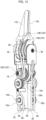
- FIG. 14 is a schematic view of the forceps device 10 illustrated in FIG. 3 omitting base member 18.
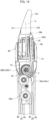
- FIG. 15 is a schematic view of the forceps device 10 illustrated in FIG. 4 omitting the base member.
- the wire 26 is passed over a first side S1 of the guide pulley 20A with respect to a vertical cross section V including the first rotating shaft 16 and being perpendicular to the second rotating shaft 22, and then fixed to the jaw pulley 24c located on the first side S1 with respect to the vertical cross section V.
- the wire 28 is passed over the first side S1 of the guide pulley 20B with respect to the vertical cross section V, and then fixed to the jaw pulley 24a located on the first side S1 with respect to the vertical cross section V.
- the wire 30 is passed over the second side S2 of the guide pulley 20D with respect to the vertical cross section V, and then fixed to the jaw pulley 24b located on the second side with respect to the vertical cross section V.
- the wire 32 is passed over the second side S2 of the guide pulley 20C with respect to the vertical cross section V, and then fixed to the jaw pulley 24d located on the second side S2 with respect to the vertical cross section V.
- the forceps device 10 includes the guide pulley 34a on the upstream side of the guide pulley 20A (on the side opposite the grasping portions) and on the second side S2 with respect to the vertical cross section V, the guide pulley 34b on the upstream side of the guide pulley 20B and on the second side S2 with respect to the vertical cross section V, the guide pulley 34c on the upstream side of the guide pulley 20C and on the first side S1 with respect to the vertical cross section V, and the guide pulley 34d on the upstream side of the guide pulley 20D and on the first side S1 with respect to the vertical cross section V.
- the grasping portions 12a and 12b of the forceps device 10 are operated inside the abdominal cavity of a patient, it is necessary to devise a way to prevent gas around the grasping portions 12a and 12b from leaking out through the forceps device 10 so that the air pressure in the abdominal cavity, which is increased to be higher than the atmospheric pressure, does not lower.
- sealing is therefore provided in a region including the base member 18.
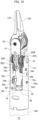
- FIG. 16 is a schematic view of the forceps device illustrated in FIG. 1 omitting wires.
- the forceps device 10 includes the pair of grasping portions 12a and 12b, the support 14 that holds the pair of grasping portions 12a and 12b, the first rotating shaft 16 that turnably supports the support 14, the base member 18 that holds the first rotating shaft 16, a plurality of wires 26, 28, 30 and 32 (not illustrated in FIG. 16 ; see FIG.
- the base member 18 is located between the grasping portions 12a and 12b and a shaft 100 of the forceps device 10.
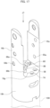
- FIG. 17 is a perspective view of the base member according to the embodiment.
- FIG. 18 is a top view of the base member illustrated in FIG. 17 as viewed in a direction J1.
- the base member 18 includes a partition part 18g having a plurality of grasping-portion-wire holes 56, 58, 60 and 62 through which the wires 26, 28, 30 and 32, respectively, pass, and the pair of arms 18a and 18b which extend from an outer edge of the partition part 18g toward the grasping part (upward in FIG. 17 ) and to which the support shafts 54a and 54b are fixed.
- the arms 18a and 18b have fitting holes 55a and 55b, respectively, into which ends of the support shafts 54a and 54b that rotatably support the pair of guide pulleys 52a and 52b are fitted.
- the partition part 18g is a partition formed between a cylindrical part 18h and the pair of arms 18a and 18b.
- the grasping-portion-wire holes 56 and 58 are a pair of grasping-portion-wire holes that are adjacent to each other at the closet distance
- the grasping-portion-wire holes 60 and 62 are a pair of grasping-portion-wire holes that are adjacent to each other at the closest distance.
- the wires 26 and 28 in a state being guided by the guide pulleys 34a and 34b are arranged together.
- a large hole through which two wires can pass needs to be formed through the partition part 18g or two small holes through each of which one wire can pass need to be formed through the partition part 18g.
- the airtightness of sealing with sealing resin which will be described later, may be lowered.
- the wall between the holes becomes thin, and the strength of an area of the base member 18 where the holes are formed may therefore be lowered.
- the wire 26 is guided by the guide pulley 52a, so that the wire 26 is separated from the wire 28.
- the wire 30 is guided by the guide pulley 52b, so that the wire 30 is separated from the wire 32.
- the grasping-portion-wire hole 56 through which the wire 26 passes and the grasping-portion-wire hole 58 through which the wire 28 passes can be separated from each other.
- the grasping-portion-wire hole 60 through which the wire 30 passes and the grasping-portion-wire hole 62 through which the wire 32 passes can be separated from each other.
- the base member 18 includes an elastic sealing member (having a type A durometer hardness of 30 to 70) arranged on one side (on one side opposite the side in which the grasping portions 12a and 12b are located) with respect to the partition part 18g.
- the sealing member is a silicone resin film having a thickness of about 0.5 to 2 mm, for example.
- the sealing member has a plurality of sealing holes at positions corresponding to those of the grasping-portion-wire holes 56, 58, 60 and 62. This enables sealing with the sealing member, with the wires 26, 28, 30 and 32 passing through the partition part 18g of the base member 18.
- the wires have a diameter ⁇ of 0.4 to 0.5 mm, and the diameter of the grasping-portion-wire holes is preferably slightly larger than the wire diameter.
- the sealing holes have a diameter that is smaller than the diameter of the grasping-portion-wire holes and smaller than the diameter (wire diameter ⁇ ) of the grasping-portion wires.
- the four grasping-portion-wire holes according to the embodiment are formed through the partition part 18g at certain distances from each other.
- the sealing holes formed at positions corresponding to those of the grasping-portion-wire holes are also separated from the adjacent sealing holes.
- the forceps device 10 includes the pair of wires 38 and 40 for turning the support 14 about the first rotating shaft 16 in addition to the wires 26, 28, 30 and 32, which are grasping-portion wires.
- the partition part 18g of the base member 18 therefore has support-wire holes 74 and 76 through which the wires 38 and 40, respectively, pass.
- the support-wire holes 74 and 76 are formed at point-symmetric positions with respect to the center Z of the partition part 18g (the central axis of the cylindrical part 18h).
- the sealing member has a plurality of sealing holes formed at positions corresponding to those of the support-wire holes 74 and 76. This enables sealing with the sealing member, with the wires 38 and 40 passing through the partition part 18g of the base member 18.
- the diameter of the support-wire holes is preferably slightly larger than the wire diameter.
- the arrangement of the pulleys of the forceps device 10 according to the embodiment is devised, so that a plurality of holes for wires formed in the partition part 18g of the base member 18 can be suitably separated from each other. This reduces such a problem as unintended integration of holes for wires in forming the sealing member having a plurality of holes for wires.
- the grasping portions 12a and 12b are bent at an angle in a control range ( ⁇ 80° in the embodiment) that prevents part of the support 14 and the grasping-portion wires 26, 28, 30, and 32 from interfering with each other.
- a control range ⁇ 80° in the embodiment
- the support 14 is freely turnable beyond the angles in the control range, and a partial region R of the support illustrated in FIG. 2 may therefore touch the grasping-portion wires 26, 28, 30, and 32.
- the forceps device 10 includes a turning restricting mechanism for restricting turning of the support to prevent the turning support 14 from touching the grasping-portion wires 26, 28, 30, and 32.
- the turning restricting mechanism includes a stopper having a face with which part of the turning support comes into contact.
- FIG. 19 is a front view of the stopper according to the embodiment.
- FIG. 20 is a drawing for explaining the stopper positioned in the base member 18.
- the stopper 82 is a block-like rectangular parallelepiped member having a flat face 82a, which faces the support 14, serving as the face with which the turning support comes into contact.
- a contact face 14b of the support 14 comes into contact with the flat face 82a (see FIGS. 2 and 7 to 9 )
- further turning of the support 14 is restricted.
- the turning restricting mechanism is achieved with a simple part.
- the support 14 is prevented from touching the grasping-portion wires 26, 28, 30, and 32, the durability of the grasping-portion wires is improved, and therefore the product life of the forceps device 10 is extended.
- the turning restricting mechanism according to the embodiment can more reliably prevent contact between the support and the grasping-portion wires.
- the contact face 14b formed at an outer edge of the support 14 is a flat surface inclined with respect to the central axis Ax (the axis passing the center Z shown in FIG. 18 ) of the base member 18 at the neutral position (the state illustrated in FIG. 3 , for example) at which the support 14 is not turned to the left or to the right.
- the support 14 is designed to come into contact with the stopper 82 when the turning angle from the neutral position becomes a contact angle ⁇ ( ⁇ ) beyond the angles ⁇ in the predetermined control range. This prevents the support 14 from turning at angles larger than the contact angle ⁇ while permitting turning at the angles ⁇ in the predetermined control range, which prevents hindrance to turning control of the support 14 by the stopper 82.
- the contact angle ⁇ is preferably 70° or larger, and may be larger than 90°. This enables control of the turning of the support at least up to 70°. If the contact angle ⁇ is too large, however, the support 14 may touch the grasping-portion wires before the support 14 comes into contact with the stopper 82. The contact angle ⁇ is therefore smaller than a turning angle at which the support 14 touches a grasping-portion wire. Specifically, the contact angle ⁇ may be smaller than 110°, or may be smaller than 100°.
- the support 14 may unintentionally touch a grasping-portion wire. Positioning of the stopper 82 is therefore important.
- the stopper 82 according to the embodiment is positioned relative to the base member 18. As a result, both the support 14 and the stopper 82 are at predetermined positions relative to the base member 18, which improves the accuracy of relative positions of the support 14 and the stopper 82.
- a through-hole 82b is formed in a side face of the stopper 82.
- the pair of arms 18a and 18b of the base member 18 holds a positioning pin 84 that is inserted in and extending through the through-hole 82b of the stopper 82.
- the stopper 82 can be accurately positioned in the direction of the central axis Ax of the base member 18.
- the pair of arms 18a and 18b holds the positioning pin 84, the strength of the arms is increased.
- the partition part 18g at the base part of the arms 18a and 18b of the base member 18 has a plurality of projections 86a, 86b, and 88 used for positioning of the stopper 82.
- the shapes and the arrangement of the projections 86a and 86b are set for positioning in a direction Ay intersecting the central axis Ax when the projections 86a and 86b come in contact with a pair of side faces 82c, which are opposite each other, of the stopper 82.
- the shape and the arrangement of the projection 88 are set for positioning in a direction Az intersecting the central axis Ax and the direction Ay when the projection 88 is fitted into a groove 82d formed at a lower portion of the stopper 82.
- the stopper 82 can be accurately positioned in the directions Ay and Az intersecting the axial direction Ax of the base member 18.
- the stopper 82 is arranged in a region surrounded by a plurality of grasping-portion wires and support wires.
- the region surrounded by the plurality of wires is occupied by the stopper 82, which prevents foreign substances from staying inside the forceps device 10 (in a region surrounded by the wires) as compared with a case where no stopper is provided.
- the arrangement of the pulleys is devised so as to improve the durability of the wires while allowing some degree of wire winding angle.
- the guide pulleys 34a and 34b are shifted toward one side (toward S2) relative to immediately below the guide pulleys 20A and 20B when the first rotating shaft 16 is viewed in front in the axial direction in a state in which the leading ends of the grasping portions 12a and 12b point upward.
- the guide pulleys 34a and 34b are arranged so that the winding angle ⁇ of the grasping-portion wires 26 and 28 around the guide pulleys 20A and 20B is 65° or larger at the neutral position at which the support 14 is not turned to the left or to the right.
- the guide pulley 52a is located upstream of the guide pulleys 34a and 34b, and the grasping-portion wire 26 runs over the guide pulley 52a.
- the guide pulley 52a is shifted toward one side (toward S2) relative to immediately below the guide pulleys 20A and 20B and shifted toward the other side (toward S1) relative to immediately below the guide pulleys 34a and 34b when the first rotating shaft 16 is viewed in front in the axial direction in the state in which the leading ends of the grasping portions 12a and 12b point upward. This increases the radius of curvature of an S-shaped curve of the grasping-portion wire 26 running over the guide pulley 34a and the guide pulley 52a.
- the guide pulleys 34d and 34c is shifted toward one side (toward S1) relative to immediately below the guide pulleys 20D and 20C when the first rotating shaft 16 is viewed in front in the axial direction in the state in which the leading ends of the grasping portions 12a and 12b point upward.
- the guide pulleys 34d and 34c are arranged so that the winding angle ⁇ of the grasping-portion wires 30 and 32 around the guide pulleys 20D and 20C is 65° or larger at the neutral position at which the support 14 is not turned to the left or to the right.
- the guide pulley 52b is located upstream of the guide pulleys 34d and 34c, and the grasping-portion wire 30 runs over the guide pulley 52b.
- the guide pulley 52b is shifted toward one side (toward S1) relative to immediately below the guide pulleys 20D and 20C and shifted toward the other side (toward S2) relative to immediately below the guide pulleys 34d and 34c when the first rotating shaft 16 is viewed in front in the axial direction in the state in which the leading ends of the grasping portions 12a and 12b point upward. This increases the radius of curvature of an S-shaped curve of the grasping-portion wire 30 running over the guide pulley 34d and the guide pulley 52a.
- the guide pulleys 52a and 52b are located on respective sides of the inner wall of the base member 18.
- the guide pulleys 52a and 52b are also rotatably supported by different support shafts 54a and 54b, respectively, which are held by the base member 18.
- the guide pulley 52b and the guide pulleys 34c and 34d can be arranged on the same side (left side in the embodiment) when the guide pulley 20D is viewed from the front.
- the base member 18 is a cylindrical part having an outer diameter of 7 to 9 mm.
- the guide pulleys 20A to 20D have a diameter of 3.0 to 3.6 mm
- the guide pulleys 34a to 34d have a diameter of 3.0 to 3.6 mm
- the guide pulleys 52a and 52b have a diameter of 3.0 to 3.6 mm.
- the present invention can be used for a manipulator of a surgical robot.
Landscapes
- Health & Medical Sciences (AREA)
- Surgery (AREA)
- Life Sciences & Earth Sciences (AREA)
- Engineering & Computer Science (AREA)
- Medical Informatics (AREA)
- Biomedical Technology (AREA)
- Heart & Thoracic Surgery (AREA)
- Nuclear Medicine, Radiotherapy & Molecular Imaging (AREA)
- Molecular Biology (AREA)
- Animal Behavior & Ethology (AREA)
- General Health & Medical Sciences (AREA)
- Public Health (AREA)
- Veterinary Medicine (AREA)
- Ophthalmology & Optometry (AREA)
- Robotics (AREA)
- Surgical Instruments (AREA)
- Manipulator (AREA)
Abstract
Description
- The present invention relates to a forceps device used for a manipulator of a surgical robot.
- Medical treatments using robots (manipulators) have recently been proposed in order to reduce the burden on operators and save manpower in medical facilities. In the field of surgery, proposals have been made for surgical manipulator systems for operators to treat patients by operating remotely-controllable surgical manipulators.
- Various surgical tools are attached to leading ends of surgical manipulators. Known surgical tools include forceps for grasping human tissue during surgery. For example,
Patent Literature 1 teaches a forceps device including a first rotating shaft (118) that turnably supports a support (107) holding a grasping part (101, 104), a base member (120) that holds the first rotating shaft, a plurality of first guide pulleys (111, 112, 113, 114) arranged coaxially with the first rotating shaft, a plurality of grasping-portion wires (102, 103, 105, 106) that transmits driving forces to move the grasping part, the grasping-portion wires running between the plurality of first guide pulleys and the grasping part without other pulleys, and a second rotating shaft (119) that turnably supports second guide pulleys located upstream of the first guide pulleys. - Patent Literature 1:
CN 107928792 A - In the forceps device mentioned above, the first guide pulleys and the second guide pulleys arranged in parallel with the central axis of the support. Thus, in order to wind the grasping-portion wires around the first guide pulleys, which are coaxial with the first rotating shaft, in accordance with the range of movement of the grasping part, the first guide pulleys and the second guide pulleys need to be close to each other. If the first guide pulleys and the second guide pulleys are close to each other, however, the radii of curvature of the wound grasping-portion wires are small. When the grasping-portion wires in this state are repeatedly pulled, the durability of the grasping-portion wires may significantly lower. Furthermore, if the tensions of the grasping-portion wires are increased so as to increase the grasping force of the grasping part of the aforementioned forceps device, the frictional force between the first rotating shaft and the support increases, which lowers the controllability of the bending movement of the support including the grasping part about the first rotating shaft.
- The present invention has been made in view of the aforementioned circumstances, and an exemplary object thereof is to provide a novel technology for improving the durability of wires or improving the controllability of the operation of the forceps device.
- To solve the aforementioned problems, a forceps device according to an aspect of the present invention includes: a grasping part; a support that holds the grasping part; a first rotating shaft that turnably supports the support; a base member that holds the first rotating shaft; a plurality of grasping-portion wires that transmit driving forces to move the grasping part; first guide pulleys arranged coaxially with the first rotating shaft, the grasping-portion wires running over the first guide pulleys; and second guide pulleys arranged upstream of the first guide pulleys, the grasping-portion wires running over the second guide pulleys. The second guide pulleys are: (i) shifted toward one side relative to immediately below the first guide pulleys when the first rotating shaft is viewed in front in an axial direction in a state in which a leading end of a grasping part points upward; and (ii) arranged so that winding angles γ of the grasping-portion wires around the first guide pulleys are 65° or larger at a neutral position at which the support is not turned to left or right.
- According to this aspect, comfortable operation control can be achieved with the turning angle of the support, which holds the grasping part, being at least within a range of ±65°.
- The winding angles γ may be 89° or larger. This enables comfortable operation control with the turning angle of the support, which holds the grasping part, being at least within a range of ±89°.
- The forceps device may further include third guide pulleys arranged upstream of the second guide pulleys, the grasping-portion wires running over the third guide pulleys. The third guide pulleys may be: (i) shifted toward one side relative to immediately below the first guide pulleys when the first rotating shaft is viewed in front in the axial direction in the state in which the leading end of the grasping part points upward; and (ii) shifted toward the other side relative to immediately below the second guide pulleys when the first rotating shaft is viewed in front in the axial direction in the state in which the leading end of the grasping part points upward. This increases the radius of curvature of an S-shaped curve of the grasping-portion wires running over the second guide pulleys and the third guide pulleys. Furthermore, as a result of the increase in the radius of curvature of the S-shaped curve of the grasping-portion wires, bending stress generated in the grasping-portion wires is lowered, and the durability of the grasping-portion wires relating to opening and closing movements of the grasping part is improved.
- The third guide pulleys may be a pair of guide pulleys arranged on respective sides of an inner wall of the base member, and the pair of third guide pulleys may be rotatably supported by different support shafts, respectively, held by the base member. This enables the third guide pulleys and the second guide pulleys to be arranged on the same side (right side or left side) when the first guide pulleys are viewed from the front.
- The base member may be a cylindrical part having an outer diameter of 7 to 9 mm, the first guide pulleys may have a diameter of 3.0 to 3.6 mm, the second guide pulleys may have a diameter of 3.0 to 3.6 mm, and the third guide pulleys may have a diameter of 3.0 to 3.6 mm. As a result, in a forceps device having a very small outer diameter, the radius of curvature of each S-shaped curve can be increased while appropriate winding angles are achieved.
- Note that any combination of the components described above, and any expression in the present invention converted to that for a method, a device, a system, and the like also remain as aspects of the present invention.
- According to the present invention, the durability of wires or the controllability of the operation of the forceps device is improved.
-
-
FIG. 1 is a perspective view of a forceps device according to an embodiment. -
FIG. 2 is a front view of the forceps device ofFIG. 1 as viewed in a direction A. -
FIG. 3 is a side view of the forceps device ofFIG. 1 as viewed in a direction B. -
FIG. 4 is a side view of the forceps device ofFIG. 1 as viewed in a direction C. -
FIG. 5 is a cross-sectional view of the forceps device illustrated inFIG. 3 along D-D. -
FIG. 6 is a perspective view of a support according to the embodiment. -
FIG. 7 is a front view of the support according to the embodiment. -
FIG. 8 is a side view of the support according to the embodiment. -
FIG. 9 is a perspective view illustrating a state in which a pair of jaw parts facing each other are to be fitted according to the embodiment. -
FIG. 10 is a perspective view of the forceps device illustrated inFIG. 1 as viewed in a direction H1. -
FIG. 11 is a perspective view of the forceps device illustrated inFIG. 1 as viewed in a direction H2. -
FIG. 12 is a perspective view of the forceps device illustrated inFIG. 1 as viewed in a direction H3. -
FIG. 13 is a perspective view of the forceps device illustrated inFIG. 1 as viewed in a direction opposite the direction H2. -
FIG. 14 is a schematic view of the forceps device illustrated inFIG. 3 omitting a base member. -
FIG. 15 is a schematic view of the forceps device illustrated inFIG. 4 omitting the base member. -
FIG. 16 is a schematic view of the forceps device illustrated inFIG. 1 omitting wires. -
FIG. 17 is a perspective view of the base member according to the embodiment. -
FIG. 18 is a top view of the base member illustrated inFIG. 17 as viewed in a direction J1. -
FIG. 19 is a front view of a stopper according to the embodiment. -
FIG. 20 is a drawing for explaining the stopper positioned in the base member. - The present invention will now be described on the basis of an embodiment with reference to the drawings. Components, members, and processes that are the same as or equivalent to each other illustrated in the drawings are represented by the same reference numerals, and redundant explanation will not be repeated where appropriate. The embodiment is not to limit the invention, but is an example, and any feature or any combination of features described in the embodiment is not necessarily essential to the invention.
-
FIG. 1 is a perspective view of a forceps device according to an embodiment.FIG. 2 is a front view of the forceps device ofFIG. 1 as viewed in a direction A.FIG. 3 is a side view of the forceps device ofFIG. 1 as viewed in a direction B.FIG. 4 is a side view of the forceps device ofFIG. 1 as viewed in a direction C. - The
forceps device 10 illustrated in the drawings includes a pair of graspingportions support 14 that holds the pair of graspingportions shaft 16 that turnably supports thesupport 14, abase member 18 that holds the first rotatingshaft 16, fourguide pulleys 20 arranged coaxially with the first rotatingshaft 16, a second rotatingshaft 22 that turnably supports the pair of graspingportions support 14, fourjaw pulleys 24 supported coaxially with the second rotatingshaft 22, fourwires guide pulleys 20 and the fourjaw pulleys 24, andwires support 14 about the first rotatingshaft 16. -
FIG. 5 is a cross-sectional view of theforceps device 10 illustrated inFIG. 3 along D-D. As illustrated inFIG. 5 , the guide pulleys 20 are rotatably supported by the firstrotating shaft 16 inserted in abearing 15 mounted on thesupport 14. As illustrated inFIG. 5 , the guide pulleys 20 according to the embodiment are arranged in such a manner that two guide pulleys 20 adjacent to each other are present on respective sides with respect to thesupport 14. - Next, the
base member 18 will be described. As illustrated inFIG. 2 andFIG. 5 , thebase member 18 according to the embodiment includes a pair ofarms rotating shaft 16, and thirdrotating shafts 36 that are held by the pair ofarms guide pulleys 34 located upstream of the guide pulleys 20. Note that a thirdrotating shaft 36 according to the embodiment is provided on each of the pair ofarms rotating shafts 36 are arranged with their axial directions being parallel to each other but not being aligned with each other. - The
arms base part 18c holding the thirdrotating shaft 36, and adistal end part 18d that holds the firstrotating shaft 16 and that is thinner than thebase part 18c. In other words, the distance between thedistal end parts 18d is larger than the distance between thebase parts 18c. Thus, as illustrated inFIG. 3 , even when thewires support 14 around the first rotating shaft 16 (in the direction of an arrow F inFIG. 3 ), thewires arms - Furthermore, the circumferential width W1 of the
distal end part 18d of thearm 18a (thearm 18b) is smaller than the circumferential width W2 of thebase part 18c thereof. Thus, a U-shaped recess is formed at thedistal end part 18d at which interference with a wire needs to be addressed, and the circumferential width of thedistal end part 18d is made larger than the circumferential width of thebase part 18c, which minimizes deterioration of the stiffness of the arm. - In addition, as illustrated in
FIG. 5 , the jaw pulleys 24 according to the embodiment have an outer diameter G1, which is larger than the distance between thebase parts 18c of the pair ofarms forceps device 10 according to the embodiment, the jaw pulleys 24 having a large outer diameter relative to the inner diameter of thecylindrical base member 18 may be used. -
FIG. 6 is a perspective view of the support according to the embodiment.FIG. 7 is a front view of the support according to the embodiment.FIG. 8 is a side view of the support according to the embodiment. As illustrated inFIG. 5 , theforceps device 10 according to the embodiment includes the pair of graspingportions support 14 that holds the pair of graspingportions rotating shaft 16 that turnably supports thesupport 14, thebase member 18 that holds the firstrotating shaft 16, and a plurality of guide pulleys 20 arranged coaxially with the firstrotating shaft 16. - As illustrated in
FIG. 7 , thesupport 14 has a circular through-hole 14a in which thebearing 15, which is a shaft bearing, is mounted. In addition, as illustrated inFIG. 6 , the firstrotating shaft 16, which rotatably supports thesupport 14, is inserted into the bearing 15 mounted on thesupport 14. The guide pulleys 20 are rotatably supported by the outer circumference of the firstrotating shaft 16. Note that each rotating shaft is not limited to a shaft that rotates by itself, but may be any shaft that is the center of rotation of a member supported thereby, and may be a shaft fixed to another member. - In the
forceps device 10 having such a structure, thesupport 14 in a state in which a plurality of guide pulleys 20 are supported by the outer circumference of the firstrotating shaft 16 is held by thebase member 18 with the firstrotating shaft 16 therebetween. This configuration facilitates improvement in the easiness of assembly as compared with a case where thesupport 14 is held directly by thebase member 18. - In addition, the
base member 18 of the embodiment has the pair ofarms rotating shaft 16 is firmly fixed in such a manner that the axial ends thereof are press-fitted to the pair ofarms arms whole base member 18 increases. - Each of the
wires portion 12a or the graspingportion 12b to move the graspingportion 12a or the graspingportion 12b. Specifically, thewire 26 and thewire 32 run over the jaw pulleys 24 for the graspingportion 12b, and the graspingportion 12b moves in an opening direction when thewire 26 is pulled and moves in a closing direction when thewire 32 is pulled. Thewire 28 and thewire 30 run over the jaw pulleys 24 for the graspingportion 12a, and the graspingportion 12a moves in a closing direction when thewire 28 is pulled and moves in an opening direction when thewire 30 is pulled. - In addition, each of the four guide pulleys 20 has a corresponding one of the
wires FIG. 2 , each of thewires pulleys 34 and runs over the corresponding one of the guide pulleys 20 from a lower side thereof (a side opposite the graspingportion - A
support pulley 42, over which thewires rotating shaft 16 run, is formed integrally with part of thesupport 14. Thesupport pulley 42 is arranged coaxially with the firstrotating shaft 16. Thus, when one of thewires support 14, the tension of thewire support pulley 42 presses thesupport 14 toward the firstrotating shaft 16. A normal force received by thesupport 14 from the firstrotating shaft 16 is thus generated, which contributes to an increase in frictional force. Alternatively, when one of thewires portions wires rotating shaft 22 via the jaw pulleys 24. The force applied to the inner circumference of the through-hole of thesupport 14 for supporting the secondrotating shaft 22 is then transmitted to the circular through-hole 14a in which thebearing 15 is mounted, and thesupport 14 is thus pressed toward the firstrotating shaft 16. In this case as well, a normal force received by thesupport 14 from the firstrotating shaft 16 is generated, which contributes to an increase in frictional force. - In the
forceps device 10 according to the embodiment, however, the bearing is provided between thesupport 14 and the firstrotating shaft 16, which reduces the frictional force between the firstrotating shaft 16 and thesupport 14. Note that, when thebearing 15 is a rolling bearing, the frictional force between the firstrotating shaft 16 and thesupport 14 can further be reduced. Consequently, the movement of the graspingportions forceps device 10 improves. Note that the bearing may be a plain bearing. The bearing 15 according to the embodiment may have a diameter of 3.6 to 4.5 mm, and the guide pulleys 20 may have a diameter of 3.0 to 3.6 mm. Thebearing 15 may have a diameter larger than that of the guide pulleys 20. - Next, jaw parts constituting the grasping portions according to the embodiment will be described in detail.
FIG. 9 is a perspective view illustrating a state in which a pair of jaw parts facing each other are to be fitted according to the embodiment.Jaw parts FIG. 9 are parts having substantially the same shapes as each other. Thejaw parts portion 12a and the graspingportion 12b, respectively, which move relative to each other to grasp an object. The graspingportion 12a is continuous with ajaw pulley 24a (first grasping portion pulley) and ajaw pulley 24b (second grasping portion pulley), which are formed in a bifurcated shape, and the graspingportion 12a and the jaw pulleys 24a and 24b integrally constitute thejaw part 50A. In addition, the graspingportion 12b is continuous with ajaw pulley 24c (third grasping portion pulley) and ajaw pulley 24d (fourth grasping portion pulley), which are formed in a bifurcated shape, and the graspingportion 12b and the jaw pulleys 24c and 24d integrally constitute thejaw part 50B. -
FIG. 10 is a perspective view of theforceps device 10 illustrated inFIG. 1 as viewed in a direction H1.FIG. 11 is a perspective view of theforceps device 10 illustrated inFIG. 1 as viewed in a direction H2.FIG. 12 is a perspective view of theforceps device 10 illustrated inFIG. 1 as viewed in a direction H3.FIG. 13 is a perspective view of theforceps device 10 illustrated inFIG. 1 as viewed in a direction opposite the direction H2. Note that the directions H1 to H3 are directions within a horizontal plane H including the firstrotating shaft 16. In addition, thebase member 18 is not illustrated inFIGS. 10 to 13 . - As illustrated in
FIGS. 10 to 13 , thejaw pulley 24a, thejaw pulley 24c, thejaw pulley 24b, and thejaw pulley 24d are rotatably supported in this order by the secondrotating shaft 22. In addition, theguide pulley 20A, theguide pulley 20B, theguide pulley 20C, and theguide pulley 20D are rotatably supported in this order by the firstrotating shaft 16. Thewires portions portions forceps device 10. This configuration can shorten the distance between the firstrotating shaft 16 and the secondrotating shaft 22 as illustrated inFIG. 10 , etc., and can therefore increase the torque (operation force) of the graspingportions forceps device 10 with high controllability of the graspingportions - Next, the manner in which the
wires wire 26 runs between theguide pulley 20A and thejaw pulley 24c. Thewire 28 runs between theguide pulley 20B and thejaw pulley 24a. Thewire 30 runs between theguide pulley 20D and thejaw pulley 24b. Thewire 32 runs between theguide pulley 20C and thejaw pulley 24d. -
FIG. 14 is a schematic view of theforceps device 10 illustrated inFIG. 3 omitting base member 18.FIG. 15 is a schematic view of theforceps device 10 illustrated inFIG. 4 omitting the base member. - As illustrated in
FIGS. 10 ,11 , and14 , thewire 26 is passed over a first side S1 of theguide pulley 20A with respect to a vertical cross section V including the firstrotating shaft 16 and being perpendicular to the secondrotating shaft 22, and then fixed to thejaw pulley 24c located on the first side S1 with respect to the vertical cross section V. Thewire 28 is passed over the first side S1 of theguide pulley 20B with respect to the vertical cross section V, and then fixed to thejaw pulley 24a located on the first side S1 with respect to the vertical cross section V. - In addition, as illustrated in
FIGS. 12 ,13 , and15 , thewire 30 is passed over the second side S2 of theguide pulley 20D with respect to the vertical cross section V, and then fixed to thejaw pulley 24b located on the second side with respect to the vertical cross section V. Thewire 32 is passed over the second side S2 of theguide pulley 20C with respect to the vertical cross section V, and then fixed to thejaw pulley 24d located on the second side S2 with respect to the vertical cross section V. As a result, the four grasping-portion wires are fixed to the four grasping portion pulleys, respectively, without intersecting with each other. - Furthermore, the
forceps device 10 includes theguide pulley 34a on the upstream side of theguide pulley 20A (on the side opposite the grasping portions) and on the second side S2 with respect to the vertical cross section V, theguide pulley 34b on the upstream side of theguide pulley 20B and on the second side S2 with respect to the vertical cross section V, theguide pulley 34c on the upstream side of theguide pulley 20C and on the first side S1 with respect to the vertical cross section V, and theguide pulley 34d on the upstream side of theguide pulley 20D and on the first side S1 with respect to the vertical cross section V. - As a result, when the
support 14 is bent in either direction about the firstrotating shaft 16, one or more of thewires support 14 is turned. More specifically, when thesupport 14 is bent from the state illustrated inFIG. 14 toward the second side S2, thewires support 14 is bent from the state illustrated inFIG. 15 toward the first side S1, thewires support 14 is bent about the firstrotating shaft 16 is stabilized. - Because the grasping
portions forceps device 10 according to the embodiment are operated inside the abdominal cavity of a patient, it is necessary to devise a way to prevent gas around the graspingportions forceps device 10 so that the air pressure in the abdominal cavity, which is increased to be higher than the atmospheric pressure, does not lower. In the present embodiment, sealing is therefore provided in a region including thebase member 18. -
FIG. 16 is a schematic view of the forceps device illustrated inFIG. 1 omitting wires. As illustrated inFIG. 16 , theforceps device 10 includes the pair of graspingportions support 14 that holds the pair of graspingportions rotating shaft 16 that turnably supports thesupport 14, thebase member 18 that holds the firstrotating shaft 16, a plurality ofwires FIG. 16 ; seeFIG. 2 ) for transmitting driving forces to the pair of graspingportions portions guide pulley 52a for guiding thewire 26, aguide pulley 52b for guiding thewire 30, andsupport shafts base member 18 is located between the graspingportions shaft 100 of theforceps device 10. -
FIG. 17 is a perspective view of the base member according to the embodiment.FIG. 18 is a top view of the base member illustrated inFIG. 17 as viewed in a direction J1. - The
base member 18 includes apartition part 18g having a plurality of grasping-portion-wire holes wires arms partition part 18g toward the grasping part (upward inFIG. 17 ) and to which thesupport shafts arms fitting holes support shafts guide pulleys - The
partition part 18g is a partition formed between acylindrical part 18h and the pair ofarms wire holes wire holes - As illustrated in
FIG. 10 , thewires wires partition part 18g, a large hole through which two wires can pass needs to be formed through thepartition part 18g or two small holes through each of which one wire can pass need to be formed through thepartition part 18g. In the case of a large hole, the airtightness of sealing with sealing resin, which will be described later, may be lowered. In contrast, in the case of two adjacent small holes, the wall between the holes becomes thin, and the strength of an area of thebase member 18 where the holes are formed may therefore be lowered. - Hence, in the
forceps device 10 according to the embodiment, thewire 26 is guided by theguide pulley 52a, so that thewire 26 is separated from thewire 28. Similarly, thewire 30 is guided by theguide pulley 52b, so that thewire 30 is separated from thewire 32. In this manner, the grasping-portion-wire hole 56 through which thewire 26 passes and the grasping-portion-wire hole 58 through which thewire 28 passes can be separated from each other. Similarly, the grasping-portion-wire hole 60 through which thewire 30 passes and the grasping-portion-wire hole 62 through which thewire 32 passes can be separated from each other. - In addition, the
base member 18 includes an elastic sealing member (having a type A durometer hardness of 30 to 70) arranged on one side (on one side opposite the side in which the graspingportions partition part 18g. The sealing member is a silicone resin film having a thickness of about 0.5 to 2 mm, for example. - The sealing member has a plurality of sealing holes at positions corresponding to those of the grasping-portion-
wire holes wires partition part 18g of thebase member 18. The wires have a diameter ϕ of 0.4 to 0.5 mm, and the diameter of the grasping-portion-wire holes is preferably slightly larger than the wire diameter. - The sealing holes have a diameter that is smaller than the diameter of the grasping-portion-wire holes and smaller than the diameter (wire diameter ϕ) of the grasping-portion wires. As a result, even when a gap is present between a grasping-portion-wire hole and a grasping-portion wire, the sealing hole and the grasping-portion wire are in close contact with each other, which reduces leakage of gas from the grasping part side to the outside of the
forceps device 10 via thebase member 18. - As illustrated in the drawings, the four grasping-portion-wire holes according to the embodiment are formed through the
partition part 18g at certain distances from each other. Thus, the sealing holes formed at positions corresponding to those of the grasping-portion-wire holes are also separated from the adjacent sealing holes. - In addition, the
forceps device 10 according to the embodiment includes the pair ofwires support 14 about the firstrotating shaft 16 in addition to thewires partition part 18g of thebase member 18 therefore has support-wire holes wires wire holes partition part 18g (the central axis of thecylindrical part 18h). - Furthermore, the sealing member has a plurality of sealing holes formed at positions corresponding to those of the support-
wire holes wires partition part 18g of thebase member 18. The diameter of the support-wire holes is preferably slightly larger than the wire diameter. Furthermore, the arrangement of the pulleys of theforceps device 10 according to the embodiment is devised, so that a plurality of holes for wires formed in thepartition part 18g of thebase member 18 can be suitably separated from each other. This reduces such a problem as unintended integration of holes for wires in forming the sealing member having a plurality of holes for wires. - In the
forceps device 10 illustrated inFIG. 2 , in a state in which the driving force for turning thesupport 14 is transmitted via thewires portions support 14 and the grasping-portion wires forceps device 10 is detached from a power source or a main unit of a robot, however, thesupport 14 is freely turnable beyond the angles in the control range, and a partial region R of the support illustrated inFIG. 2 may therefore touch the grasping-portion wires - Thus, the
forceps device 10 according to the embodiment includes a turning restricting mechanism for restricting turning of the support to prevent the turningsupport 14 from touching the grasping-portion wires FIG. 19 is a front view of the stopper according to the embodiment.FIG. 20 is a drawing for explaining the stopper positioned in thebase member 18. - The
stopper 82 is a block-like rectangular parallelepiped member having aflat face 82a, which faces thesupport 14, serving as the face with which the turning support comes into contact. When acontact face 14b of thesupport 14 comes into contact with theflat face 82a (seeFIGS. 2 and7 to 9 ), further turning of thesupport 14 is restricted. In this manner, the turning restricting mechanism is achieved with a simple part. Furthermore, because thesupport 14 is prevented from touching the grasping-portion wires forceps device 10 is extended. - As described above, because the
support 14 and thestopper 82 directly come in contact with each other, the turning restricting mechanism according to the embodiment can more reliably prevent contact between the support and the grasping-portion wires. - Furthermore, as illustrated in
FIG. 7 , thecontact face 14b formed at an outer edge of thesupport 14 is a flat surface inclined with respect to the central axis Ax (the axis passing the center Z shown inFIG. 18 ) of thebase member 18 at the neutral position (the state illustrated inFIG. 3 , for example) at which thesupport 14 is not turned to the left or to the right. Thesupport 14 is designed to come into contact with thestopper 82 when the turning angle from the neutral position becomes a contact angle β (α<β) beyond the angles α in the predetermined control range. This prevents thesupport 14 from turning at angles larger than the contact angle β while permitting turning at the angles α in the predetermined control range, which prevents hindrance to turning control of thesupport 14 by thestopper 82. - Note that the contact angle β is preferably 70° or larger, and may be larger than 90°. This enables control of the turning of the support at least up to 70°. If the contact angle β is too large, however, the
support 14 may touch the grasping-portion wires before thesupport 14 comes into contact with thestopper 82. The contact angle β is therefore smaller than a turning angle at which thesupport 14 touches a grasping-portion wire. Specifically, the contact angle β may be smaller than 110°, or may be smaller than 100°. - Note that, if the contact angle β varies, the
support 14 may unintentionally touch a grasping-portion wire. Positioning of thestopper 82 is therefore important. Thestopper 82 according to the embodiment is positioned relative to thebase member 18. As a result, both thesupport 14 and thestopper 82 are at predetermined positions relative to thebase member 18, which improves the accuracy of relative positions of thesupport 14 and thestopper 82. - Specific positioning in the embodiment will be explained. As illustrated in
FIG. 19 , a through-hole 82b is formed in a side face of thestopper 82. In addition, as illustrated inFIG. 20 , the pair ofarms base member 18 holds apositioning pin 84 that is inserted in and extending through the through-hole 82b of thestopper 82. Thus, thestopper 82 can be accurately positioned in the direction of the central axis Ax of thebase member 18. Furthermore, because the pair ofarms positioning pin 84, the strength of the arms is increased. - In addition, the
partition part 18g at the base part of thearms base member 18 has a plurality ofprojections stopper 82. The shapes and the arrangement of theprojections projections stopper 82. In addition, the shape and the arrangement of theprojection 88 are set for positioning in a direction Az intersecting the central axis Ax and the direction Ay when theprojection 88 is fitted into agroove 82d formed at a lower portion of thestopper 82. Thus, thestopper 82 can be accurately positioned in the directions Ay and Az intersecting the axial direction Ax of thebase member 18. - In addition, as illustrated in
FIGS. 10 and18 , thestopper 82 is arranged in a region surrounded by a plurality of grasping-portion wires and support wires. Thus, the region surrounded by the plurality of wires is occupied by thestopper 82, which prevents foreign substances from staying inside the forceps device 10 (in a region surrounded by the wires) as compared with a case where no stopper is provided. - In the
forceps device 10 according to the embodiment, the arrangement of the pulleys is devised so as to improve the durability of the wires while allowing some degree of wire winding angle. Specifically, as illustrated inFIG. 14 , the guide pulleys 34a and 34b are shifted toward one side (toward S2) relative to immediately below the guide pulleys 20A and 20B when the firstrotating shaft 16 is viewed in front in the axial direction in a state in which the leading ends of the graspingportions portion wires support 14 is not turned to the left or to the right. - This enables comfortable operation control with the turning angle of the
support 14, which holds the graspingportions portions - The
guide pulley 52a is located upstream of the guide pulleys 34a and 34b, and the grasping-portion wire 26 runs over theguide pulley 52a. Theguide pulley 52a is shifted toward one side (toward S2) relative to immediately below the guide pulleys 20A and 20B and shifted toward the other side (toward S1) relative to immediately below the guide pulleys 34a and 34b when the firstrotating shaft 16 is viewed in front in the axial direction in the state in which the leading ends of the graspingportions portion wire 26 running over theguide pulley 34a and theguide pulley 52a. Furthermore, as a result of the increase in the radius of curvature of the S-shaped curve of the grasping-portion wire 26, bending stress generated in the grasping-portion wire 26 is lowered, and the durability of the grasping-portion wires relating to opening and closing movements of the graspingportions - Similarly, as illustrated in
FIG. 15 , the guide pulleys 34d and 34c is shifted toward one side (toward S1) relative to immediately below the guide pulleys 20D and 20C when the firstrotating shaft 16 is viewed in front in the axial direction in the state in which the leading ends of the graspingportions portion wires support 14 is not turned to the left or to the right. - The
guide pulley 52b is located upstream of the guide pulleys 34d and 34c, and the grasping-portion wire 30 runs over theguide pulley 52b. Theguide pulley 52b is shifted toward one side (toward S1) relative to immediately below the guide pulleys 20D and 20C and shifted toward the other side (toward S2) relative to immediately below the guide pulleys 34d and 34c when the firstrotating shaft 16 is viewed in front in the axial direction in the state in which the leading ends of the graspingportions portion wire 30 running over theguide pulley 34d and theguide pulley 52a. Furthermore, as a result of the increase in the radius of curvature of the S-shaped curve of the grasping-portion wire 30, bending stress generated in the grasping-portion wire 30 is lowered, and the durability of the grasping-portion wires relating to opening and closing movements of the graspingportions - Note that, as illustrated in
FIG. 16 , the guide pulleys 52a and 52b are located on respective sides of the inner wall of thebase member 18. The guide pulleys 52a and 52b are also rotatably supported bydifferent support shafts base member 18. This enables theguide pulley 52a and the guide pulleys 34a and 34b to be arranged on the same side (left side in the embodiment) when theguide pulley 20A is viewed from the front. Similarly, theguide pulley 52b and the guide pulleys 34c and 34d can be arranged on the same side (left side in the embodiment) when theguide pulley 20D is viewed from the front. - Note that the
base member 18 according to the embodiment is a cylindrical part having an outer diameter of 7 to 9 mm. Furthermore, the guide pulleys 20A to 20D have a diameter of 3.0 to 3.6 mm, the guide pulleys 34a to 34d have a diameter of 3.0 to 3.6 mm, and the guide pulleys 52a and 52b have a diameter of 3.0 to 3.6 mm. As a result, in a forceps device having a very small outer diameter, the radius of curvature of each S-shaped curve can be increased while appropriate winding angles are achieved. - While the present invention has been described above with reference to the embodiment, the present invention is not limited to the embodiment, and any combination or substitution of components in the embodiment as appropriate is included in the present invention. In addition, modifications such as combinations, changes in the order of processes, and various changes in design in the embodiment may be made on the embodiment on the basis of knowledge of a person skilled in the art, and such modified embodiments may be within the scope of the present invention.
- The present invention can be used for a manipulator of a surgical robot.
-
- 10
- forceps device
- 12a
- grasping portion
- 12b
- grasping portion
- 14
- support
- 14a
- through-hole
- 14b
- contact face
- 15
- bearing
- 16
- first rotating shaft
- 18
- base member
- 18a
- arm
- 18b
- arm
- 18g
- partition part
- 20
- guide pulley
- 22
- second rotating shaft
- 24
- jaw pulley
- 26, 28, 30, 32
- grasping-portion wire
- 34
- guide pulley
- 36
- third rotating shaft
- 52a, 52b
- guide pulley
- 82
- stopper
- 82a
- flat face
- 82b
- through-hole
- 82c
- side face
- 82d
- groove
- 84
- positioning pin
- 86a, 86b
- projection
- 88
- projection
Claims (5)
- A forceps device comprising:a grasping part;a support that holds the grasping part;a first rotating shaft that turnably supports the support;a base member that holds the first rotating shaft;a plurality of grasping-portion wires that transmit driving forces to move the grasping part;first guide pulleys arranged coaxially with the first rotating shaft, the grasping-portion wires running over the first guide pulleys; andsecond guide pulleys arranged upstream of the first guide pulleys, the grasping-portion wires running over the second guide pulleys, whereinthe second guide pulleys are:(i) shifted toward one side relative to immediately below the first guide pulleys when the first rotating shaft is viewed in front in an axial direction in a state in which a leading end of a grasping part points upward; and(ii) arranged so that winding angles γ of the grasping-portion wires around the first guide pulleys are 65° or larger at a neutral position at which the support is not turned to left or right.
- The forceps device according to claim 1, wherein
the winding angles γ are 89° or larger. - The forceps device according to claim 1 or 2, further comprising:third guide pulleys arranged upstream of the second guide pulleys, the grasping-portion wires running over the third guide pulleys, whereinthe third guide pulleys are:(i) shifted toward one side relative to immediately below the first guide pulleys when the first rotating shaft is viewed in front in the axial direction in the state in which the leading end of the grasping part points upward; and(ii) shifted toward the other side relative to immediately below the second guide pulleys when the first rotating shaft is viewed in front in the axial direction in the state in which the leading end of the grasping part points upward.
- The forceps device according to claim 3, whereinthe third guide pulleys are a pair of guide pulleys arranged on respective sides of an inner wall of the base member, andthe pair of third guide pulleys are rotatably supported by different support shafts, respectively, held by the base member.
- The forceps device according to claim 3 or 4, whereinthe base member is a cylindrical part having an outer diameter of 7 to 9 mm,the first guide pulleys have a diameter of 3.0 to 3.6 mm,the second guide pulleys have a diameter of 3.0 to 3.6 mm, andthe third guide pulleys have a diameter of 3.0 to 3.6 mm.
Applications Claiming Priority (1)
| Application Number | Priority Date | Filing Date | Title |
|---|---|---|---|
| PCT/JP2022/001339 WO2023135792A1 (en) | 2022-01-17 | 2022-01-17 | Forceps device |
Publications (3)
| Publication Number | Publication Date |
|---|---|
| EP4458307A1 true EP4458307A1 (en) | 2024-11-06 |
| EP4458307A4 EP4458307A4 (en) | 2025-03-12 |
| EP4458307B1 EP4458307B1 (en) | 2025-12-31 |
Family
ID=87278652
Family Applications (1)
| Application Number | Title | Priority Date | Filing Date |
|---|---|---|---|
| EP22920317.9A Active EP4458307B1 (en) | 2022-01-17 | 2022-01-17 | pliers device |
Country Status (5)
| Country | Link |
|---|---|
| US (1) | US20240366248A1 (en) |
| EP (1) | EP4458307B1 (en) |
| JP (1) | JP7390089B1 (en) |
| CN (1) | CN118555939A (en) |
| WO (1) | WO2023135792A1 (en) |
Families Citing this family (2)
| Publication number | Priority date | Publication date | Assignee | Title |
|---|---|---|---|---|
| WO2023135791A1 (en) * | 2022-01-17 | 2023-07-20 | リバーフィールド株式会社 | Forceps device |
| WO2026023064A1 (en) * | 2024-07-26 | 2026-01-29 | リバーフィールド株式会社 | Forceps device |
Family Cites Families (8)
| Publication number | Priority date | Publication date | Assignee | Title |
|---|---|---|---|---|
| EP1329363A1 (en) * | 2002-01-16 | 2003-07-23 | Alcan Technology & Management AG | Deformable motor vehicle energy absorbing member |
| JP3944108B2 (en) * | 2003-03-31 | 2007-07-11 | 株式会社東芝 | Power transmission mechanism and manipulator for medical manipulator |
| US11116534B2 (en) * | 2013-12-11 | 2021-09-14 | Covidien Lp | Surgical device for grasping and shearing |
| GB201521812D0 (en) * | 2015-12-10 | 2016-01-27 | Cambridge Medical Robotics Ltd | Driving a surgical instrument articulation |
| GB201521804D0 (en) * | 2015-12-10 | 2016-01-27 | Cambridge Medical Robotics Ltd | Pulley arrangement for articulating a surgical instrument |
| CN107928792A (en) | 2017-12-11 | 2018-04-20 | 哈尔滨思哲睿智能医疗设备有限公司 | One kind is used for minimally invasive surgery robot multiple degrees of freedom needle holder |
| JP6896317B1 (en) * | 2020-09-10 | 2021-06-30 | リバーフィールド株式会社 | Forceps device |
| JP6943522B1 (en) * | 2020-12-08 | 2021-10-06 | リバーフィールド株式会社 | Forceps device and base parts |
-
2022
- 2022-01-17 CN CN202280086069.3A patent/CN118555939A/en active Pending
- 2022-01-17 JP JP2023544775A patent/JP7390089B1/en active Active
- 2022-01-17 EP EP22920317.9A patent/EP4458307B1/en active Active
- 2022-01-17 WO PCT/JP2022/001339 patent/WO2023135792A1/en not_active Ceased
-
2024
- 2024-07-16 US US18/773,808 patent/US20240366248A1/en active Pending
Also Published As
| Publication number | Publication date |
|---|---|
| EP4458307A4 (en) | 2025-03-12 |
| US20240366248A1 (en) | 2024-11-07 |
| WO2023135792A1 (en) | 2023-07-20 |
| CN118555939A (en) | 2024-08-27 |
| JP7390089B1 (en) | 2023-12-01 |
| EP4458307B1 (en) | 2025-12-31 |
| JPWO2023135792A1 (en) | 2023-07-20 |
Similar Documents
| Publication | Publication Date | Title |
|---|---|---|
| US20240366248A1 (en) | Forceps device | |
| EP4252693B1 (en) | Forceps device and base component | |
| JP3912251B2 (en) | manipulator | |
| EP3282952B1 (en) | Tension management apparatus for cable-driven transmission | |
| US20230210546A1 (en) | Forceps device | |
| US8906002B2 (en) | Bending joint mechanism, surgical instrument having this bending joint mechanism, and manipulator having this bending joint mechanism | |
| US20240366250A1 (en) | Forceps device | |
| US20240366249A1 (en) | Forceps device | |
| US20220313296A1 (en) | Surgical device | |
| KR20160124795A (en) | Articulatable members having constrained motion, and related devices and methods | |
| WO2022135356A1 (en) | Instrument effector, instrument effector assembly and surgical instrument | |
| WO2024022048A1 (en) | End effector mechanism of surgical instrument, and surgical instrument | |
| EP3395280A1 (en) | Activation member, activation mechanism, and method for fabricating activation mechanism | |
| CN116570216A (en) | Active bending section, insertion part and endoscope | |
| JP7396764B2 (en) | Slider and surgical tools | |
| CN221181313U (en) | Mounting structure and interventional medical device | |
| US20220313299A1 (en) | Surgical device | |
| US20260138293A1 (en) | Elbow-wrist robotic tool | |
| JP7775777B2 (en) | Roller pump | |
| CN120227150A (en) | Driving wire guide assembly and surgical instrument |
Legal Events
| Date | Code | Title | Description |
|---|---|---|---|
| STAA | Information on the status of an ep patent application or granted ep patent |
Free format text: STATUS: THE INTERNATIONAL PUBLICATION HAS BEEN MADE |
|
| PUAI | Public reference made under article 153(3) epc to a published international application that has entered the european phase |
Free format text: ORIGINAL CODE: 0009012 |
|
| STAA | Information on the status of an ep patent application or granted ep patent |
Free format text: STATUS: REQUEST FOR EXAMINATION WAS MADE |
|
| 17P | Request for examination filed |
Effective date: 20240801 |
|
| AK | Designated contracting states |
Kind code of ref document: A1 Designated state(s): AL AT BE BG CH CY CZ DE DK EE ES FI FR GB GR HR HU IE IS IT LI LT LU LV MC MK MT NL NO PL PT RO RS SE SI SK SM TR |
|
| A4 | Supplementary search report drawn up and despatched |
Effective date: 20250210 |
|
| RIC1 | Information provided on ipc code assigned before grant |
Ipc: A61B 17/29 20060101ALN20250204BHEP Ipc: A61B 34/30 20160101AFI20250204BHEP |
|
| DAV | Request for validation of the european patent (deleted) | ||
| DAX | Request for extension of the european patent (deleted) | ||
| GRAP | Despatch of communication of intention to grant a patent |
Free format text: ORIGINAL CODE: EPIDOSNIGR1 |
|
| STAA | Information on the status of an ep patent application or granted ep patent |
Free format text: STATUS: GRANT OF PATENT IS INTENDED |
|
| RIC1 | Information provided on ipc code assigned before grant |
Ipc: A61B 34/30 20160101AFI20250801BHEP Ipc: A61B 17/29 20060101ALN20250801BHEP |
|
| INTG | Intention to grant announced |
Effective date: 20250905 |
|
| RIN1 | Information on inventor provided before grant (corrected) |
Inventor name: TAKIKAWA, KYOHEI |
|
| GRAS | Grant fee paid |
Free format text: ORIGINAL CODE: EPIDOSNIGR3 |
|
| GRAA | (expected) grant |
Free format text: ORIGINAL CODE: 0009210 |
|
| STAA | Information on the status of an ep patent application or granted ep patent |
Free format text: STATUS: THE PATENT HAS BEEN GRANTED |
|
| AK | Designated contracting states |
Kind code of ref document: B1 Designated state(s): AL AT BE BG CH CY CZ DE DK EE ES FI FR GB GR HR HU IE IS IT LI LT LU LV MC MK MT NL NO PL PT RO RS SE SI SK SM TR |
|
| REG | Reference to a national code |
Ref country code: CH Ref legal event code: F10 Free format text: ST27 STATUS EVENT CODE: U-0-0-F10-F00 (AS PROVIDED BY THE NATIONAL OFFICE) Effective date: 20251231 Ref country code: GB Ref legal event code: FG4D |
|
| REG | Reference to a national code |
Ref country code: DE Ref legal event code: R096 Ref document number: 602022028194 Country of ref document: DE |
|
| P01 | Opt-out of the competence of the unified patent court (upc) registered |
Free format text: CASE NUMBER: UPC_APP_0017780_4458307/2025 Effective date: 20251216 |
|
| REG | Reference to a national code |
Ref country code: IE Ref legal event code: FG4D |
|
| PGFP | Annual fee paid to national office [announced via postgrant information from national office to epo] |
Ref country code: GB Payment date: 20260219 Year of fee payment: 5 |
|
| REG | Reference to a national code |
Ref country code: LT Ref legal event code: MG9D |
|
| PG25 | Lapsed in a contracting state [announced via postgrant information from national office to epo] |
Ref country code: NO Free format text: LAPSE BECAUSE OF FAILURE TO SUBMIT A TRANSLATION OF THE DESCRIPTION OR TO PAY THE FEE WITHIN THE PRESCRIBED TIME-LIMIT Effective date: 20260331 |
|
| PGFP | Annual fee paid to national office [announced via postgrant information from national office to epo] |
Ref country code: DE Payment date: 20260107 Year of fee payment: 5 |
|
| PG25 | Lapsed in a contracting state [announced via postgrant information from national office to epo] |
Ref country code: FI Free format text: LAPSE BECAUSE OF FAILURE TO SUBMIT A TRANSLATION OF THE DESCRIPTION OR TO PAY THE FEE WITHIN THE PRESCRIBED TIME-LIMIT Effective date: 20251231 Ref country code: HR Free format text: LAPSE BECAUSE OF FAILURE TO SUBMIT A TRANSLATION OF THE DESCRIPTION OR TO PAY THE FEE WITHIN THE PRESCRIBED TIME-LIMIT Effective date: 20251231 |
|
| PGFP | Annual fee paid to national office [announced via postgrant information from national office to epo] |
Ref country code: AT Payment date: 20260301 Year of fee payment: 5 |
|
| PG25 | Lapsed in a contracting state [announced via postgrant information from national office to epo] |
Ref country code: RS Free format text: LAPSE BECAUSE OF FAILURE TO SUBMIT A TRANSLATION OF THE DESCRIPTION OR TO PAY THE FEE WITHIN THE PRESCRIBED TIME-LIMIT Effective date: 20260331 |
|
| PGFP | Annual fee paid to national office [announced via postgrant information from national office to epo] |
Ref country code: FR Payment date: 20260219 Year of fee payment: 5 |
|
| PG25 | Lapsed in a contracting state [announced via postgrant information from national office to epo] |
Ref country code: LV Free format text: LAPSE BECAUSE OF FAILURE TO SUBMIT A TRANSLATION OF THE DESCRIPTION OR TO PAY THE FEE WITHIN THE PRESCRIBED TIME-LIMIT Effective date: 20251231 |
|
| PG25 | Lapsed in a contracting state [announced via postgrant information from national office to epo] |
Ref country code: BG Free format text: LAPSE BECAUSE OF FAILURE TO SUBMIT A TRANSLATION OF THE DESCRIPTION OR TO PAY THE FEE WITHIN THE PRESCRIBED TIME-LIMIT Effective date: 20251231 |
|
| REG | Reference to a national code |
Ref country code: NL Ref legal event code: MP Effective date: 20251231 |
|
| REG | Reference to a national code |
Ref country code: AT Ref legal event code: MK05 Ref document number: 1872359 Country of ref document: AT Kind code of ref document: T Effective date: 20251231 |
|
| PG25 | Lapsed in a contracting state [announced via postgrant information from national office to epo] |
Ref country code: NL Free format text: LAPSE BECAUSE OF FAILURE TO SUBMIT A TRANSLATION OF THE DESCRIPTION OR TO PAY THE FEE WITHIN THE PRESCRIBED TIME-LIMIT Effective date: 20251231 |
|
| PG25 | Lapsed in a contracting state [announced via postgrant information from national office to epo] |
Ref country code: LT Free format text: LAPSE BECAUSE OF FAILURE TO SUBMIT A TRANSLATION OF THE DESCRIPTION OR TO PAY THE FEE WITHIN THE PRESCRIBED TIME-LIMIT Effective date: 20251231 |
|
| PG25 | Lapsed in a contracting state [announced via postgrant information from national office to epo] |
Ref country code: SM Free format text: LAPSE BECAUSE OF FAILURE TO SUBMIT A TRANSLATION OF THE DESCRIPTION OR TO PAY THE FEE WITHIN THE PRESCRIBED TIME-LIMIT Effective date: 20251231 |
|
| PG25 | Lapsed in a contracting state [announced via postgrant information from national office to epo] |
Ref country code: ES Free format text: LAPSE BECAUSE OF FAILURE TO SUBMIT A TRANSLATION OF THE DESCRIPTION OR TO PAY THE FEE WITHIN THE PRESCRIBED TIME-LIMIT Effective date: 20251231 |
|
| PG25 | Lapsed in a contracting state [announced via postgrant information from national office to epo] |
Ref country code: PL Free format text: LAPSE BECAUSE OF FAILURE TO SUBMIT A TRANSLATION OF THE DESCRIPTION OR TO PAY THE FEE WITHIN THE PRESCRIBED TIME-LIMIT Effective date: 20251231 |
|
| PG25 | Lapsed in a contracting state [announced via postgrant information from national office to epo] |
Ref country code: IT Free format text: LAPSE BECAUSE OF FAILURE TO SUBMIT A TRANSLATION OF THE DESCRIPTION OR TO PAY THE FEE WITHIN THE PRESCRIBED TIME-LIMIT Effective date: 20251231 |
|
| PG25 | Lapsed in a contracting state [announced via postgrant information from national office to epo] |
Ref country code: AT Free format text: LAPSE BECAUSE OF FAILURE TO SUBMIT A TRANSLATION OF THE DESCRIPTION OR TO PAY THE FEE WITHIN THE PRESCRIBED TIME-LIMIT Effective date: 20251231 |
|
| PG25 | Lapsed in a contracting state [announced via postgrant information from national office to epo] |
Ref country code: EE Free format text: LAPSE BECAUSE OF FAILURE TO SUBMIT A TRANSLATION OF THE DESCRIPTION OR TO PAY THE FEE WITHIN THE PRESCRIBED TIME-LIMIT Effective date: 20251231 |
|
| PG25 | Lapsed in a contracting state [announced via postgrant information from national office to epo] |
Ref country code: IS Free format text: LAPSE BECAUSE OF FAILURE TO SUBMIT A TRANSLATION OF THE DESCRIPTION OR TO PAY THE FEE WITHIN THE PRESCRIBED TIME-LIMIT Effective date: 20260430 Ref country code: PT Free format text: LAPSE BECAUSE OF FAILURE TO SUBMIT A TRANSLATION OF THE DESCRIPTION OR TO PAY THE FEE WITHIN THE PRESCRIBED TIME-LIMIT Effective date: 20260430 |
|
| PG25 | Lapsed in a contracting state [announced via postgrant information from national office to epo] |
Ref country code: CZ Free format text: LAPSE BECAUSE OF FAILURE TO SUBMIT A TRANSLATION OF THE DESCRIPTION OR TO PAY THE FEE WITHIN THE PRESCRIBED TIME-LIMIT Effective date: 20251231 |
|
| PG25 | Lapsed in a contracting state [announced via postgrant information from national office to epo] |
Ref country code: SK Free format text: LAPSE BECAUSE OF FAILURE TO SUBMIT A TRANSLATION OF THE DESCRIPTION OR TO PAY THE FEE WITHIN THE PRESCRIBED TIME-LIMIT Effective date: 20251231 |
|
| PG25 | Lapsed in a contracting state [announced via postgrant information from national office to epo] |
Ref country code: SE Free format text: LAPSE BECAUSE OF FAILURE TO SUBMIT A TRANSLATION OF THE DESCRIPTION OR TO PAY THE FEE WITHIN THE PRESCRIBED TIME-LIMIT Effective date: 20251231 |