EP4458212A1 - Inclinable concealed shelf support bracket - Google Patents
Inclinable concealed shelf support bracket Download PDFInfo
- Publication number
- EP4458212A1 EP4458212A1 EP24173938.2A EP24173938A EP4458212A1 EP 4458212 A1 EP4458212 A1 EP 4458212A1 EP 24173938 A EP24173938 A EP 24173938A EP 4458212 A1 EP4458212 A1 EP 4458212A1
- Authority
- EP
- European Patent Office
- Prior art keywords
- plate
- support bracket
- pin
- shelf support
- curved surface
- Prior art date
- Legal status (The legal status is an assumption and is not a legal conclusion. Google has not performed a legal analysis and makes no representation as to the accuracy of the status listed.)
- Granted
Links
Images



Classifications
-
- A—HUMAN NECESSITIES
- A47—FURNITURE; DOMESTIC ARTICLES OR APPLIANCES; COFFEE MILLS; SPICE MILLS; SUCTION CLEANERS IN GENERAL
- A47B—TABLES; DESKS; OFFICE FURNITURE; CABINETS; DRAWERS; GENERAL DETAILS OF FURNITURE
- A47B96/00—Details of cabinets, racks or shelf units not covered by a single one of groups A47B43/00 - A47B95/00; General details of furniture
- A47B96/02—Shelves
- A47B96/027—Cantilever shelves
- A47B96/028—Cantilever shelves characterised by support bracket location means, e.g. fixing means between support bracket and shelf
-
- A—HUMAN NECESSITIES
- A47—FURNITURE; DOMESTIC ARTICLES OR APPLIANCES; COFFEE MILLS; SPICE MILLS; SUCTION CLEANERS IN GENERAL
- A47B—TABLES; DESKS; OFFICE FURNITURE; CABINETS; DRAWERS; GENERAL DETAILS OF FURNITURE
- A47B96/00—Details of cabinets, racks or shelf units not covered by a single one of groups A47B43/00 - A47B95/00; General details of furniture
- A47B96/06—Brackets or similar supporting means for cabinets, racks or shelves
-
- A—HUMAN NECESSITIES
- A47—FURNITURE; DOMESTIC ARTICLES OR APPLIANCES; COFFEE MILLS; SPICE MILLS; SUCTION CLEANERS IN GENERAL
- A47B—TABLES; DESKS; OFFICE FURNITURE; CABINETS; DRAWERS; GENERAL DETAILS OF FURNITURE
- A47B95/00—Fittings for furniture
-
- A—HUMAN NECESSITIES
- A47—FURNITURE; DOMESTIC ARTICLES OR APPLIANCES; COFFEE MILLS; SPICE MILLS; SUCTION CLEANERS IN GENERAL
- A47B—TABLES; DESKS; OFFICE FURNITURE; CABINETS; DRAWERS; GENERAL DETAILS OF FURNITURE
- A47B96/00—Details of cabinets, racks or shelf units not covered by a single one of groups A47B43/00 - A47B95/00; General details of furniture
- A47B96/06—Brackets or similar supporting means for cabinets, racks or shelves
- A47B96/066—Supporting means received within an edge of the shelf
-
- A—HUMAN NECESSITIES
- A47—FURNITURE; DOMESTIC ARTICLES OR APPLIANCES; COFFEE MILLS; SPICE MILLS; SUCTION CLEANERS IN GENERAL
- A47B—TABLES; DESKS; OFFICE FURNITURE; CABINETS; DRAWERS; GENERAL DETAILS OF FURNITURE
- A47B96/00—Details of cabinets, racks or shelf units not covered by a single one of groups A47B43/00 - A47B95/00; General details of furniture
- A47B96/06—Brackets or similar supporting means for cabinets, racks or shelves
- A47B96/07—Brackets or similar supporting means for cabinets, racks or shelves adjustable in themselves
-
- A—HUMAN NECESSITIES
- A47—FURNITURE; DOMESTIC ARTICLES OR APPLIANCES; COFFEE MILLS; SPICE MILLS; SUCTION CLEANERS IN GENERAL
- A47B—TABLES; DESKS; OFFICE FURNITURE; CABINETS; DRAWERS; GENERAL DETAILS OF FURNITURE
- A47B57/00—Cabinets, racks or shelf units, characterised by features for adjusting shelves or partitions
- A47B57/04—Cabinets, racks or shelf units, characterised by features for adjusting shelves or partitions with means for adjusting the inclination of the shelves
- A47B57/045—Cantilever shelves
Definitions
- the present invention relates to the furniture sector.
- it relates to a device for fixing a shelf to a wall.
- a concealed shelf support bracket which can be adjusted in several ways.
- a known concealed shelf support bracket is fixed to the wall and is made so as to have a pin which projects substantially perpendicularly from the wall. The pin is designed to penetrate inside a hole formed in the thickness of the shelf to be supported.
- the axes of the holes are parallel to each other and lie in a plane parallel to the plane of the shelf.
- the known support brackets are fixed with the axes situated at different heights, one being a few millimetres higher or lower than the other one.
- the axes of the respective pins are situated a distance which does not coincide with the distance between the respective holes in the shelf.
- the distance between the axes of the two pins is greater or smaller than the distance between the axes of the holes in the shelf. In either case, it is not possible to mount the shelf.
- IT1391441 describes a concealed shelf support bracket which allows several adjustments to be made in order to compensate for any imprecision during mounting or defects present in the shelf to be mounted.
- the Applicant has considered that there exists the need to be able to incline the pin with respect to the horizontal in order to compensate for any imprecision in the wall to which the shelf must be fixed or to provide a "preload".
- the fitter tries to mount the shelf so that it is slightly inclined upwards, namely is "preloaded". In this way, when the shelf is subject to the load, it is arranged in a substantially horizontal manner.
- the Applicant has defined the object of providing a concealed shelf support bracket which allows the shelf to be mounted also, if necessary, with an inclination different from the horizontal position.
- This object is achieved with a pin configured to engage with a concave surface of the wall plate.
- a concealed shelf support bracket comprising a plate configured to be fixed to a wall and a pin projecting from the plate
- the second curved surface is made integral with the pin.
- the pin comprises a threaded longitudinal hole for a screw passing through a window of the plate for removably fastening the pin to the plate.
- the window has a width and/or height greater than the diameter of the shank of the screw.
- the plate comprises a recessed central part and the screw head is seated in the recessed central part of the plate.
- the recessed central part is curved and the head of the screw comprises a surface which is correspondingly curved.
- the pin also comprises two opposite flat surfaces for screwing the pin with respect to the screw.
- the shank also comprises a plurality of grooves for a safety retaining screw.
- the first curved surface and the second curved surface are cylindrical surfaces. In alternative embodiments, the first curved surface and the second curved surface are spherical surfaces.
- each wing of the plate comprises a hole and/or an eyelet, for instance a vertical-axis eyelet.
- each wing of the plate comprises a thickness of 1-5 mm, wherein the shelf support bracket is configured to be inset in a milled zone in the edge of the shelf facing the wall to which the shelf support bracket must be fixed.
- each wing of the plate comprises ends which are rounded, for example semi-circular ends.
- the shelf support bracket 1 comprises a wall plate 2 (or also simply “plate”), a pin 3 and a screw 4 for fixing the pin 3 to the plate 2. According to embodiments, optionally the shelf support bracket 1 also comprises a support adapter 5 between the pin 3 and the plate 2.
- the plate 2 may have any shape, not necessarily the shape shown in the figures by way of example.
- the plate 2 may be made of metallic material, for example steel or aluminium. Alternatively, it may be made of thermoplastic material or a composite material.
- the plate 2 is a flat body which extends in a main direction and defines a longitudinal axis 21. Considering that the plate 2 must be inset in a milled zone 61 in the edge of the shelf 6 facing the wall to which the support bracket must be fixed, preferably the height of the plate 2 is not greater than the thickness of the shelf 6. For example it may be about 2 cm or 3 cm.
- the plate 2 has ends which are rounded, for example semi-circular. This is advantageous because it allows the milled receiving zone 61 in the shelf 6 to be made using a normal circular milling tool.
- the plate 2 is symmetrical with respect to a transverse plane and comprises a central part 22 and two wings 23 which extend from the central part 22.
- the plate 2 comprises a first face 2a and a second face 2b.
- the first face 2a is the face directed towards the shelf 6 while the second face 2b is directed towards the wall 10.
- the wings 23 of the plate 2 lie preferably in the same plane.
- the first face 2a projects in the region of the central part 22 from the plane defined by the wings 23.
- the second face 2b is recessed in the region of the central part 22 with respect to the plane defined by the wings 23.
- a hole 24 and/or an eyelet 25 is provided for each wing 23 of the plate 2.
- two vertical-axis eyelets 25 and a circular hole 24 may be provided.
- the vertical-axis eyelets 25 allow adjustment of the height of the shelf 6 with respect to the wall 10.
- the circular hole 24 is for a screw configured to fix the plate (and therefore the bracket) to shelf when the bracket is arranged in a milled area in the thickness of the shelf.
- the first face 2a of the plate 2, in the region of the central part 22, is curved (projecting) with respect to the wings 23 and the second face 2b of the plate is recessed with respect to the wings 23 in the region of the central part 22.
- the convex curvature of the central part is indicated by the number 221, while the opposite concave curvature (in the recessed part of the plate) is indicated by the number 222.
- the central part 22 of the plate 2 is curved, for example with a substantially cylindrical surface.
- the radius of curvature may be for example about 10-20 mm, for example about 15 mm. In another embodiment, it may be about 20-40 mm, for example about 30 mm.
- the curvature 221 and 222 is clearly visible, for example, in the cross-sections of Figures 6.5 and 6.6 .
- the positive (projecting, convex) curvature 221 is substantially equal to the negative (recessed, concave) curvature 222.
- the central part 22 of the plate comprises a central window 26.
- the central window 26 may have any shape, but preferably is substantially square or rectangular. The reasons for which this shape is preferred will become clear below.
- the corners of the central window 26 are rounded.
- the pin 3 is a substantially cylindrical body with a circular cross-section having a first end 31 and a second end 32.
- the first end 31 comprises a longitudinal hole 33.
- the longitudinal hole 33 is a threaded blind hole.
- two opposite flat surfaces 34 are provided in the vicinity of the first end 31 for an adjustment spanner.
- a circular groove 35 (or several circular grooves) is/are formed at the second end 32 for engagement by a safety retaining screw 36 ( Figs. 7.1, 7.2, 7.3 ).
- the screw 4 for fixing the pin 3 to the plate is shown, for example, in the exploded view of Fig. 3 .
- the screw 4 comprises a threaded shank 41 and a head 42.
- the threaded shank 41 is configured to engage inside the threaded longitudinal hole 33 of the pin 3.
- the head 42 of the screw 4 has its face 42a which is directed towards the threaded shank 41 curved so as to match the recessed curvature in the central part 22 of the plate.
- the head 42 of the screw 4 has preferably a size such as not to allow complete relative rotation thereof with respect to the plate 2. At the most, the screw 4 may rotate a few degrees with respect to the plate 2, but may not perform a complete revolution.
- the central window 26 has a width greater than the diameter of the shank of the screw 4. For example, it may be about 1.5 - 2 times the diameter of the shank of the screw 4. For example, in the case of a screw 4 with a diameter of 8 mm, the width of the central window 26 may be 13.5 mm and, in the case of a screw 4 with a diameter of 5 mm, the width of the central window 26 may be 9 mm.
- the central window 26 has a height greater than the diameter of the shank of the screw 4. For example, it may be about 1-2 mm greater than the diameter of the shank of the screw 4. For example, in the case of a screw 4 with a diameter of 8 mm, the height of the central window 26 may be about 10 mm and, in the case of a screw 4 with a diameter of 5 mm, the height of the central window 26 may be 6 mm.
- the shelf support bracket 1 also comprises a support adapter 5 between the pin 3 and the plate 2.
- the first end 31 of the pin 3 could be shaped substantially like the adapter 5.
- the support adapter 5 is substantially in the form of a washer with a central opening 51 for the shank 41 of the screw 4.
- the support adapter 5 comprises a first face 52 and a second face 53.
- the first face 52 is configured to be directly in contact with the curved central part 22 of the plate 2.
- the first face 52 of the adapter 5 has a negative, i.e. recessed, curvature corresponding to the positive curvature of the central part 22 of the plate 2.
- the second face 53 is configured to be directly in contact with the first end 31 of the pin 3.
- the second face 53 is preferably flat.
- the shelf support bracket 1 may be preassembled by inserting the shank 41 of the screw 4 into the central window 26 of the plate 2, causing the shank 41 of the screw 4 to pass through the central opening 51 of the adapter 5 and screwing the screw 4 inside the threaded longitudinal hole 33 of the pin 3. Preassembly may also be performed without using tools.
- a fixed spanner may be used to engage the two opposite flat surfaces 34 of the pin 3. However, it is advisable to perform the definitive locking after firmly fixing the support bracket 1 to a wall 10.
- the eyelets 25 which extend in the vertical direction allow the position of the support bracket 1 to be adjusted vertically with respect to a wall 10.
- the horizontal adjustment is instead obtained owing to the fact that the pin may be moved to the right or to the left.
- the movement is limited by the dimensions of the shank 41 of the screw 4 with respect to the central window 26 of the plate 2.
- Fig. 4.1 shows the pin 3 in its position further to the right, when the shank 41 of the screw 4 is situated against the right-hand wall 10 of the central window 26.
- Fig. 4.2 shows the pin 3 in its central position, when the shank 41 of the screw 4 is situated between the right-hand wall and the left-hand wall of the central window 26.
- Fig. 4.3 shows the pin 3 in its position further to the left, when the shank 41 of the screw 4 is situated against the left-hand wall of the central window 26.
- the pin 3 it is possible to vary the inclination of the pin 3 with respect to the plate 2. In fact, for as long as the pin 3 is not completely locked with respect to the plate 2, it may be inclined upwards or downwards, according to the specific need. When the correct inclination is reached, the pin 3 may be firmly locked in position.
- Figures 7.1, 7.2 and 7.3 show three cross-sections through a shelf 6 with the support bracket 1 according to the invention.
- the pin 3 of the support bracket 1 is inclined upwards so as to "preload” the shelf 6.
- the pin 3 of the support bracket 1 is arranged horizontally.
- the pin 3 of the support bracket 1 is inclined downwards.
- the inclination of the pin 3 corresponds to a relative rotation of the curved surface of the central part 22 of the plate 2 and the corresponding surface 52 of the adapter 5 which directly faces the curved surface of the central part 22.
- the inclination of the pin 3 and its horizontal position are limited by the dimensions of the central window in relation, obviously, to the diameter of the shank 41 of the screw 4.
- the inclination of the shelf 6 may be varied by simply pulling out slightly the shelf 6 from the support bracket 1 (stably fixed to the wall) so as to be able to operate on the opposite flat surfaces of the pin 3.
- the fitter locks the pin 3 with respect to the plate 2 and pushes the shelf 6 fully back in place again.
- a safety retaining screw 36 may be used, said screw being screwed in until it engages one of the grooves 35 which are situated close to the second end 32 of the pin 3.
Landscapes
- Furniture Connections (AREA)
Abstract
wherein the pin (3) is removably fastened to the plate (2),
wherein the plate comprises a first curved surface (221) which is convex or concave.
wherein the pin comprises a second curved surface (52) having a curvature substantially matching the curvature of the first curved surface, and
wherein a relative movement of the first curved surface and the second curved surface allows an angle orientation of the pin with respect to the plate.
Description
- The present invention relates to the furniture sector. In particular, it relates to a device for fixing a shelf to a wall. Even more particularly, it relates to a concealed shelf support bracket which can be adjusted in several ways.
- For some time concealed brackets for supporting a shelf in a way such that they remain substantially invisible both on the upper surface and on the bottom surface of the shelf have been known. A known concealed shelf support bracket is fixed to the wall and is made so as to have a pin which projects substantially perpendicularly from the wall. The pin is designed to penetrate inside a hole formed in the thickness of the shelf to be supported.
- Usually, depending on the length of the shelf to be fixed to the wall, two or more support brackets are provided for each shelf to be supported. Therefore, two or more holes are provided in the thickness of each shelf.
- Typically, in the case of a flat shelf to be fixed in a horizontal position, the axes of the holes are parallel to each other and lie in a plane parallel to the plane of the shelf.
- Ideally, by fixing the support brackets in such a way that the pins project from the wall at the same height from the ground, perfectly horizontal and perfectly perpendicular to the wall, it would be possible to fix a wall shelf in a perfectly horizontal configuration.
- However, such a situation is merely theoretical. In fact, generally, the known support brackets are fixed with the axes situated at different heights, one being a few millimetres higher or lower than the other one.
- Moreover, frequently, once two support brackets have been fixed to the wall, the axes of the respective pins are situated a distance which does not coincide with the distance between the respective holes in the shelf. In other words, even though the fitter is careful when mounting the support brackets on the wall, it often happens that the distance between the axes of the two pins is greater or smaller than the distance between the axes of the holes in the shelf. In either case, it is not possible to mount the shelf.
-
IT1391441 - The Applicant has carefully examined the concealed shelf support brackets of the known type.
- The Applicant has considered that there exists the need to be able to incline the pin with respect to the horizontal in order to compensate for any imprecision in the wall to which the shelf must be fixed or to provide a "preload". As is known, if the shelf must support relatively heavy objects, the fitter tries to mount the shelf so that it is slightly inclined upwards, namely is "preloaded". In this way, when the shelf is subject to the load, it is arranged in a substantially horizontal manner. On other occasions there may be the need to incline the shelf support bracket downwards, for example when the wall to which the support bracket is fixed is not perfectly vertical.
- The Applicant has defined the object of providing a concealed shelf support bracket which allows the shelf to be mounted also, if necessary, with an inclination different from the horizontal position.
- This object is achieved with a pin configured to engage with a concave surface of the wall plate.
- According to one aspect, a concealed shelf support bracket comprising a plate configured to be fixed to a wall and a pin projecting from the plate is provided,
- wherein the pin is removably fastened to the plate,
- wherein the plate comprises a flat body extending in a main direction and comprising a longitudinal axis, a central part and two wings which extend from the central part, a first face and a second face, which, in use, is directed towards the wall,
- wherein the central part comprises a first curved surface which is convex or concave,
- wherein either
- a. the pin comprises a second curved surface having a curvature substantially matching the curvature of the first curved surface, or
- b. the shelf support bracket further comprises a support adapter between the pin and the plate and wherein the support adapter comprises a second curved surface substantially matching the curvature of the first curved surface, and
- wherein a relative movement of the first curved surface and the second curved surface allows an angle orientation of the pin with respect to the plate.
- According to embodiments, the second curved surface is made integral with the pin.
- According to embodiments, the pin comprises a threaded longitudinal hole for a screw passing through a window of the plate for removably fastening the pin to the plate.
- According to embodiments, the window has a width and/or height greater than the diameter of the shank of the screw.
- According to embodiments, the plate comprises a recessed central part and the screw head is seated in the recessed central part of the plate.
- According to embodiments, the recessed central part is curved and the head of the screw comprises a surface which is correspondingly curved.
- According to embodiments, the pin also comprises two opposite flat surfaces for screwing the pin with respect to the screw.
- According to embodiments, the shank also comprises a plurality of grooves for a safety retaining screw.
- According to embodiments, the first curved surface and the second curved surface are cylindrical surfaces. In alternative embodiments, the first curved surface and the second curved surface are spherical surfaces.
- According to embodiments, each wing of the plate comprises a hole and/or an eyelet, for instance a vertical-axis eyelet.
- According to embodiments, each wing of the plate comprises a thickness of 1-5 mm, wherein the shelf support bracket is configured to be inset in a milled zone in the edge of the shelf facing the wall to which the shelf support bracket must be fixed.
- According to embodiments, each wing of the plate comprises ends which are rounded, for example semi-circular ends.
- The invention will become entirely clear from the following description, provided purely by way of a non-limiting example, to be read with reference to the attached figures, in which:
-
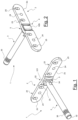
Fig. 1 is a first axonometric view of the concealed shelf support bracket according to an embodiment of the present invention; -
Fig. 2 is a second axonometric view of the concealed shelf support bracket according to an embodiment of the present invention; -
Fig. 3 is an exploded view of the shelf support bracket according toFigures 1 and 2 ; -
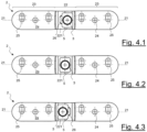
Figs. 4.1 - 4.3 are front views of the shelf support bracket according toFigures 1-3 which show three different positions of the pin with respect to the plate; -
Fig. 5.1 is a partially sectioned side view of the pin of the shelf support bracket according toFigures 1-3 ; -
Fig. 5.2 is an axonometric view of the pin of the shelf support bracket according toFigures 1-3 ; -
Figs. 6.1 - 6.3 are three views of the plate of the shelf support bracket according toFigures 1-3 ; -
Figs. 6.4 - 6.6 are three cross-sections obtained fromFig. 6.3 ; and -
Figs. 7.1, 7.2 and 7.3 are cross-sections through a shelf with the support bracket according to the present invention with the pin inclined at three different inclinations. - The
shelf support bracket 1 according to the present invention comprises a wall plate 2 (or also simply "plate"), apin 3 and a screw 4 for fixing thepin 3 to theplate 2. According to embodiments, optionally theshelf support bracket 1 also comprises asupport adapter 5 between thepin 3 and theplate 2. - The
plate 2 may have any shape, not necessarily the shape shown in the figures by way of example. Theplate 2 may be made of metallic material, for example steel or aluminium. Alternatively, it may be made of thermoplastic material or a composite material. - Preferably, the
plate 2 is a flat body which extends in a main direction and defines alongitudinal axis 21. Considering that theplate 2 must be inset in a milledzone 61 in the edge of the shelf 6 facing the wall to which the support bracket must be fixed, preferably the height of theplate 2 is not greater than the thickness of the shelf 6. For example it may be about 2 cm or 3 cm. - Preferably, the
plate 2 has ends which are rounded, for example semi-circular. This is advantageous because it allows the milled receivingzone 61 in the shelf 6 to be made using a normal circular milling tool. - Preferably, the
plate 2 is symmetrical with respect to a transverse plane and comprises acentral part 22 and twowings 23 which extend from thecentral part 22. Theplate 2 comprises afirst face 2a and asecond face 2b. During use, thefirst face 2a is the face directed towards the shelf 6 while thesecond face 2b is directed towards thewall 10. - The
wings 23 of theplate 2 lie preferably in the same plane. According to embodiments, thefirst face 2a projects in the region of thecentral part 22 from the plane defined by thewings 23. According to embodiments, thesecond face 2b is recessed in the region of thecentral part 22 with respect to the plane defined by thewings 23. - According to embodiments, for each
wing 23 of theplate 2, ahole 24 and/or aneyelet 25 is provided. For example, two vertical-axis eyelets 25 and acircular hole 24 may be provided. The vertical-axis eyelets 25 allow adjustment of the height of the shelf 6 with respect to thewall 10. Thecircular hole 24 is for a screw configured to fix the plate (and therefore the bracket) to shelf when the bracket is arranged in a milled area in the thickness of the shelf. - As mentioned above, the
first face 2a of theplate 2, in the region of thecentral part 22, is curved (projecting) with respect to thewings 23 and thesecond face 2b of the plate is recessed with respect to thewings 23 in the region of thecentral part 22. The convex curvature of the central part is indicated by thenumber 221, while the opposite concave curvature (in the recessed part of the plate) is indicated by thenumber 222. - Preferably, the
central part 22 of theplate 2 is curved, for example with a substantially cylindrical surface. The radius of curvature may be for example about 10-20 mm, for example about 15 mm. In another embodiment, it may be about 20-40 mm, for example about 30 mm. Thecurvature Figures 6.5 and 6.6 . According to embodiments, the positive (projecting, convex)curvature 221 is substantially equal to the negative (recessed, concave)curvature 222. - The
central part 22 of the plate comprises acentral window 26. Thecentral window 26 may have any shape, but preferably is substantially square or rectangular. The reasons for which this shape is preferred will become clear below. Preferably, the corners of thecentral window 26 are rounded. Thepin 3 is a substantially cylindrical body with a circular cross-section having afirst end 31 and asecond end 32. According to embodiments, thefirst end 31 comprises a longitudinal hole 33. The longitudinal hole 33 is a threaded blind hole. According to embodiments, two oppositeflat surfaces 34 are provided in the vicinity of thefirst end 31 for an adjustment spanner. - According to embodiments, a circular groove 35 (or several circular grooves) is/are formed at the
second end 32 for engagement by a safety retaining screw 36 (Figs. 7.1, 7.2, 7.3 ). - The screw 4 for fixing the
pin 3 to the plate is shown, for example, in the exploded view ofFig. 3 . The screw 4 comprises a threadedshank 41 and ahead 42. The threadedshank 41 is configured to engage inside the threaded longitudinal hole 33 of thepin 3. Thehead 42 of the screw 4 has itsface 42a which is directed towards the threadedshank 41 curved so as to match the recessed curvature in thecentral part 22 of the plate. Thehead 42 of the screw 4 has preferably a size such as not to allow complete relative rotation thereof with respect to theplate 2. At the most, the screw 4 may rotate a few degrees with respect to theplate 2, but may not perform a complete revolution. - The
central window 26 has a width greater than the diameter of the shank of the screw 4. For example, it may be about 1.5 - 2 times the diameter of the shank of the screw 4. For example, in the case of a screw 4 with a diameter of 8 mm, the width of thecentral window 26 may be 13.5 mm and, in the case of a screw 4 with a diameter of 5 mm, the width of thecentral window 26 may be 9 mm. - The
central window 26 has a height greater than the diameter of the shank of the screw 4. For example, it may be about 1-2 mm greater than the diameter of the shank of the screw 4. For example, in the case of a screw 4 with a diameter of 8 mm, the height of thecentral window 26 may be about 10 mm and, in the case of a screw 4 with a diameter of 5 mm, the height of thecentral window 26 may be 6 mm. - The
shelf support bracket 1 also comprises asupport adapter 5 between thepin 3 and theplate 2. Alternatively, thefirst end 31 of thepin 3 could be shaped substantially like theadapter 5. - The
support adapter 5 is substantially in the form of a washer with acentral opening 51 for theshank 41 of the screw 4. Thesupport adapter 5 comprises afirst face 52 and a second face 53. Thefirst face 52 is configured to be directly in contact with the curvedcentral part 22 of theplate 2. For this reason, thefirst face 52 of theadapter 5 has a negative, i.e. recessed, curvature corresponding to the positive curvature of thecentral part 22 of theplate 2. The second face 53 is configured to be directly in contact with thefirst end 31 of thepin 3. For this reason, the second face 53 is preferably flat. - The
shelf support bracket 1 according to the present invention may be preassembled by inserting theshank 41 of the screw 4 into thecentral window 26 of theplate 2, causing theshank 41 of the screw 4 to pass through thecentral opening 51 of theadapter 5 and screwing the screw 4 inside the threaded longitudinal hole 33 of thepin 3. Preassembly may also be performed without using tools. In order to firmly lock thepin 3 with respect to theplate 2 advantageously a fixed spanner may be used to engage the two oppositeflat surfaces 34 of thepin 3. However, it is advisable to perform the definitive locking after firmly fixing thesupport bracket 1 to awall 10. - The
eyelets 25 which extend in the vertical direction allow the position of thesupport bracket 1 to be adjusted vertically with respect to awall 10. - The horizontal adjustment is instead obtained owing to the fact that the pin may be moved to the right or to the left. The movement is limited by the dimensions of the
shank 41 of the screw 4 with respect to thecentral window 26 of theplate 2. -
Fig. 4.1 shows thepin 3 in its position further to the right, when theshank 41 of the screw 4 is situated against the right-hand wall 10 of thecentral window 26. -
Fig. 4.2 shows thepin 3 in its central position, when theshank 41 of the screw 4 is situated between the right-hand wall and the left-hand wall of thecentral window 26. -
Fig. 4.3 shows thepin 3 in its position further to the left, when theshank 41 of the screw 4 is situated against the left-hand wall of thecentral window 26. - According to the present invention it is possible to vary the inclination of the
pin 3 with respect to theplate 2. In fact, for as long as thepin 3 is not completely locked with respect to theplate 2, it may be inclined upwards or downwards, according to the specific need. When the correct inclination is reached, thepin 3 may be firmly locked in position. -
Figures 7.1, 7.2 and 7.3 show three cross-sections through a shelf 6 with thesupport bracket 1 according to the invention. In the first figure it can be seen that thepin 3 of thesupport bracket 1 is inclined upwards so as to "preload" the shelf 6. In the second figure it can be seen that thepin 3 of thesupport bracket 1 is arranged horizontally. Finally, in the third figure, it can be seem that thepin 3 of thesupport bracket 1 is inclined downwards. - In fact, the inclination of the
pin 3 corresponds to a relative rotation of the curved surface of thecentral part 22 of theplate 2 and thecorresponding surface 52 of theadapter 5 which directly faces the curved surface of thecentral part 22. As mentioned, the inclination of thepin 3 and its horizontal position are limited by the dimensions of the central window in relation, obviously, to the diameter of theshank 41 of the screw 4. - Advantageously, during assembly, the inclination of the shelf 6 may be varied by simply pulling out slightly the shelf 6 from the support bracket 1 (stably fixed to the wall) so as to be able to operate on the opposite flat surfaces of the
pin 3. After defining the desired inclination of the shelf 6, the fitter locks thepin 3 with respect to theplate 2 and pushes the shelf 6 fully back in place again. - As shown in
Figures 7.1, 7.2 and 7.3 , in order to prevent the shelf 6 from coming away from thesupport bracket 1, asafety retaining screw 36 may be used, said screw being screwed in until it engages one of thegrooves 35 which are situated close to thesecond end 32 of thepin 3.
Claims (13)
- A concealed shelf support bracket (1) comprising a plate (2) configured to be fixed to a wall (10) and a pin (3) projecting from the plate (2),wherein the pin (3) is removably fastened to the plate (2),wherein the plate (2) comprises a flat body extending in a main direction and comprising a longitudinal axis (21), a central part (22) and two wings (23) which extend from the central part (22), a first face (2a) and a second face (2b), which, in use, is directed towards the wall (10),wherein the central part (22) comprises a first curved surface (221) which is convex or concave,wherein eithera. the pin (3) comprises a second curved surface (52) having a curvature substantially matching the curvature of the first curved surface (221), orb. the shelf support bracket (1) further comprises a support adapter (5) between the pin (3) and the plate (2) and wherein the support adapter (5) comprises a second curved surface (52) substantially matching the curvature of the first curved surface (221), andwherein a relative movement of the first curved surface (221) and the second curved surface (52) allows an angle orientation of the pin (3) with respect to the plate (2).
- The shelf support bracket (1) of claim 1, wherein the second curved surface (52) is made integral with the pin (3).
- The shelf support bracket (1) of claim 1 or 2, wherein the pin (3) comprises a threaded longitudinal hole (33) for a screw (4) passing through a window (26) of the plate (2) for removably fastening the pin (3) to the plate (2).
- The shelf support bracket (1) of claim 3, wherein the window (26) has a width and/or height greater than the diameter of the shank (41) of the screw (4).
- The shelf support bracket (1) of claim 3 or 4, wherein the plate (2) comprises a recessed central part and wherein the screw head (42) is seated in the recessed central part of the plate (2).
- The shelf support bracket (1) of claim 5, wherein the recessed central part is curved and the head (42) of the screw (4) comprises a surface (42a) which is correspondingly curved.
- The shelf support bracket (1) of any one of claims 3-6, wherein the pin (3) further comprises two opposite flat surfaces (34) for screwing the pin (3) with respect to the screw (4).
- The shelf support bracket (1) of any one of the preceding claims, wherein the pin (3) further comprises a plurality of grooves (35) for a safety retaining screw (36).
- The shelf support bracket (1) of any one of the preceding claims, wherein the first curved surface (221) and the second curved surface (52) are cylindrical surfaces.
- The shelf support bracket (1) of any one of claims 1-8, wherein the first curved surface (221) and the second curved surface (52) are spherical surfaces.
- The shelf support bracket (1) of any one of the preceding claims, wherein each wing (23) of the plate (2) comprises a hole (24) and/or an eyelet (25), for instance a vertical-axis eyelet (25).
- The shelf support bracket (1) of any one of the preceding claims, wherein each wing (23) of the plate (2) comprises a thickness of 1-5 mm, wherein the shelf support bracket (1) is configured to be inset in a milled zone (61) in the edge of the shelf (6) facing the wall to which the shelf support bracket must be fixed.
- The shelf support bracket (1) of any one of the preceding claims, wherein each wing (23) of the plate (2) comprises ends which are rounded, for example semi-circular ends.
Applications Claiming Priority (1)
| Application Number | Priority Date | Filing Date | Title |
|---|---|---|---|
| IT102023000008943A IT202300008943A1 (en) | 2023-05-05 | 2023-05-05 | Tiltable concealed shelf bracket |
Publications (3)
| Publication Number | Publication Date |
|---|---|
| EP4458212A1 true EP4458212A1 (en) | 2024-11-06 |
| EP4458212B1 EP4458212B1 (en) | 2026-03-04 |
| EP4458212C0 EP4458212C0 (en) | 2026-03-04 |
Family
ID=87419268
Family Applications (1)
| Application Number | Title | Priority Date | Filing Date |
|---|---|---|---|
| EP24173938.2A Active EP4458212B1 (en) | 2023-05-05 | 2024-05-02 | Inclinable concealed shelf support bracket |
Country Status (4)
| Country | Link |
|---|---|
| EP (1) | EP4458212B1 (en) |
| CN (1) | CN118892255A (en) |
| ES (1) | ES3070599T3 (en) |
| IT (1) | IT202300008943A1 (en) |
Cited By (1)
| Publication number | Priority date | Publication date | Assignee | Title |
|---|---|---|---|---|
| RU240026U1 (en) * | 2025-08-26 | 2025-12-22 | Общество с ограниченной ответственностью "Медтехника Реботек" (ООО "Медтехника-Р") | BRACKET FOR EXTENSION OF THE MEDICAL BED |
Citations (4)
| Publication number | Priority date | Publication date | Assignee | Title |
|---|---|---|---|---|
| EP1844682A2 (en) * | 2006-04-14 | 2007-10-17 | Ferramenta Livenza S.r.l. | Concealed-type support arrangement for brackets, shelves and the like |
| IT1391441B1 (en) | 2008-10-14 | 2011-12-23 | O M M S A S Di Ing Roberto Natale Mariani & C | ADJUSTABLE ADJUSTMENT SHELF |
| ITUD20100161A1 (en) * | 2010-08-27 | 2012-02-28 | Eureka S R L | "REGGI SHELF" |
| WO2017081515A1 (en) * | 2015-11-12 | 2017-05-18 | Siso A/S | An adjustable support bracket for a shelf or similar element |
-
2023
- 2023-05-05 IT IT102023000008943A patent/IT202300008943A1/en unknown
-
2024
- 2024-05-02 EP EP24173938.2A patent/EP4458212B1/en active Active
- 2024-05-02 ES ES24173938T patent/ES3070599T3/en active Active
- 2024-05-06 CN CN202410545692.1A patent/CN118892255A/en active Pending
Patent Citations (4)
| Publication number | Priority date | Publication date | Assignee | Title |
|---|---|---|---|---|
| EP1844682A2 (en) * | 2006-04-14 | 2007-10-17 | Ferramenta Livenza S.r.l. | Concealed-type support arrangement for brackets, shelves and the like |
| IT1391441B1 (en) | 2008-10-14 | 2011-12-23 | O M M S A S Di Ing Roberto Natale Mariani & C | ADJUSTABLE ADJUSTMENT SHELF |
| ITUD20100161A1 (en) * | 2010-08-27 | 2012-02-28 | Eureka S R L | "REGGI SHELF" |
| WO2017081515A1 (en) * | 2015-11-12 | 2017-05-18 | Siso A/S | An adjustable support bracket for a shelf or similar element |
Non-Patent Citations (1)
| Title |
|---|
| O.M.M.: "MN300 - Reggi mensola - Shelf support - O.M.M. Made in Italy", 20 October 2023 (2023-10-20), XP093192715, Retrieved from the Internet <URL:https://www.youtube.com/watch?v=Ek0cSe3d_Xk> [retrieved on 20240805] * |
Cited By (1)
| Publication number | Priority date | Publication date | Assignee | Title |
|---|---|---|---|---|
| RU240026U1 (en) * | 2025-08-26 | 2025-12-22 | Общество с ограниченной ответственностью "Медтехника Реботек" (ООО "Медтехника-Р") | BRACKET FOR EXTENSION OF THE MEDICAL BED |
Also Published As
| Publication number | Publication date |
|---|---|
| IT202300008943A1 (en) | 2024-11-05 |
| EP4458212B1 (en) | 2026-03-04 |
| ES3070599T3 (en) | 2026-06-16 |
| CN118892255A (en) | 2024-11-05 |
| EP4458212C0 (en) | 2026-03-04 |
Similar Documents
| Publication | Publication Date | Title |
|---|---|---|
| US8739367B2 (en) | Hidden door hinge | |
| US6053481A (en) | Security fence rail bracket | |
| US10476425B2 (en) | Height adjustment bracket for roof applications | |
| AU2009100265A4 (en) | Positioning member for preventing detachment of axle | |
| US8925258B1 (en) | Wall and door panel adjustment device | |
| CA3019448C (en) | Panel member securing structure and panel member securing tool | |
| US20190177973A1 (en) | Panel mount for securing a panel to an adjoining structure | |
| US7895712B2 (en) | Door hinge for a motor vehicle | |
| US8388074B1 (en) | Kitchen appliance having an adjustable door panel | |
| EP4458212B1 (en) | Inclinable concealed shelf support bracket | |
| WO2011088622A1 (en) | A tiltable flat panel display mount | |
| US20030075656A1 (en) | Detachable arm limiting assembly | |
| CN112888832B (en) | Assembly for a hinge for the articulated connection of a leaf to a frame about a hinge axis, and hinge comprising such an assembly | |
| ES2448471T3 (en) | Hardware with high load capacity to connect two components | |
| KR20190133816A (en) | Hinge assembly for a door | |
| EP3482087B1 (en) | Fixing device | |
| EP3359823B1 (en) | Plate mount | |
| US20030221392A1 (en) | Paneling system and method of installing | |
| JP2017145612A (en) | Seismic reinforcement bracket | |
| US4485602A (en) | Wall panel positive alignment device | |
| US10879836B2 (en) | Mounting assembly for mounting a solar panel | |
| EP1754929B1 (en) | Adjustable mount | |
| EP3632265A1 (en) | Device for attaching a furniture component to a wall | |
| EP2902700B1 (en) | Mounting block | |
| KR101242716B1 (en) | Separate-typed lane guide bar assembly |
Legal Events
| Date | Code | Title | Description |
|---|---|---|---|
| PUAI | Public reference made under article 153(3) epc to a published international application that has entered the european phase |
Free format text: ORIGINAL CODE: 0009012 |
|
| STAA | Information on the status of an ep patent application or granted ep patent |
Free format text: STATUS: THE APPLICATION HAS BEEN PUBLISHED |
|
| AK | Designated contracting states |
Kind code of ref document: A1 Designated state(s): AL AT BE BG CH CY CZ DE DK EE ES FI FR GB GR HR HU IE IS IT LI LT LU LV MC ME MK MT NL NO PL PT RO RS SE SI SK SM TR |
|
| STAA | Information on the status of an ep patent application or granted ep patent |
Free format text: STATUS: REQUEST FOR EXAMINATION WAS MADE |
|
| 17P | Request for examination filed |
Effective date: 20250429 |
|
| GRAP | Despatch of communication of intention to grant a patent |
Free format text: ORIGINAL CODE: EPIDOSNIGR1 |
|
| STAA | Information on the status of an ep patent application or granted ep patent |
Free format text: STATUS: GRANT OF PATENT IS INTENDED |
|
| RIC1 | Information provided on ipc code assigned before grant |
Ipc: A47B 96/07 20060101AFI20251006BHEP Ipc: A47B 57/04 20060101ALN20251006BHEP |
|
| INTG | Intention to grant announced |
Effective date: 20251015 |
|
| GRAS | Grant fee paid |
Free format text: ORIGINAL CODE: EPIDOSNIGR3 |
|
| GRAA | (expected) grant |
Free format text: ORIGINAL CODE: 0009210 |
|
| STAA | Information on the status of an ep patent application or granted ep patent |
Free format text: STATUS: THE PATENT HAS BEEN GRANTED |
|
| AK | Designated contracting states |
Kind code of ref document: B1 Designated state(s): AL AT BE BG CH CY CZ DE DK EE ES FI FR GB GR HR HU IE IS IT LI LT LU LV MC ME MK MT NL NO PL PT RO RS SE SI SK SM TR |
|
| REG | Reference to a national code |
Ref country code: CH Ref legal event code: F10 Free format text: ST27 STATUS EVENT CODE: U-0-0-F10-F00 (AS PROVIDED BY THE NATIONAL OFFICE) Effective date: 20260304 Ref country code: GB Ref legal event code: FG4D |
|
| REG | Reference to a national code |
Ref country code: IE Ref legal event code: FG4D |
|
| REG | Reference to a national code |
Ref country code: DE Ref legal event code: R096 Ref document number: 602024002921 Country of ref document: DE |
|
| U01 | Request for unitary effect filed |
Effective date: 20260327 |
|
| U07 | Unitary effect registered |
Designated state(s): AT BE BG DE DK EE FI FR IT LT LU LV MT NL PT RO SE SI Effective date: 20260402 |
|
| REG | Reference to a national code |
Ref country code: ES Ref legal event code: FG2A Ref document number: 3070599 Country of ref document: ES Kind code of ref document: T3 Effective date: 20260616 |
|
| PG25 | Lapsed in a contracting state [announced via postgrant information from national office to epo] |
Ref country code: RS Free format text: LAPSE BECAUSE OF FAILURE TO SUBMIT A TRANSLATION OF THE DESCRIPTION OR TO PAY THE FEE WITHIN THE PRESCRIBED TIME-LIMIT Effective date: 20260604 |
|
| PGFP | Annual fee paid to national office [announced via postgrant information from national office to epo] |
Ref country code: ES Payment date: 20260605 Year of fee payment: 3 |
|
| PG25 | Lapsed in a contracting state [announced via postgrant information from national office to epo] |
Ref country code: PL Free format text: LAPSE BECAUSE OF FAILURE TO SUBMIT A TRANSLATION OF THE DESCRIPTION OR TO PAY THE FEE WITHIN THE PRESCRIBED TIME-LIMIT Effective date: 20260304 |
|
| PG25 | Lapsed in a contracting state [announced via postgrant information from national office to epo] |
Ref country code: GR Free format text: LAPSE BECAUSE OF FAILURE TO SUBMIT A TRANSLATION OF THE DESCRIPTION OR TO PAY THE FEE WITHIN THE PRESCRIBED TIME-LIMIT Effective date: 20260605 |
|
| PG25 | Lapsed in a contracting state [announced via postgrant information from national office to epo] |
Ref country code: NO Free format text: LAPSE BECAUSE OF FAILURE TO SUBMIT A TRANSLATION OF THE DESCRIPTION OR TO PAY THE FEE WITHIN THE PRESCRIBED TIME-LIMIT Effective date: 20260604 |
|
| PG25 | Lapsed in a contracting state [announced via postgrant information from national office to epo] |
Ref country code: HR Free format text: LAPSE BECAUSE OF FAILURE TO SUBMIT A TRANSLATION OF THE DESCRIPTION OR TO PAY THE FEE WITHIN THE PRESCRIBED TIME-LIMIT Effective date: 20260304 |
|
| PGFP | Annual fee paid to national office [announced via postgrant information from national office to epo] |
Ref country code: TR Payment date: 20260522 Year of fee payment: 3 |
|
| U20 | Renewal fee for the european patent with unitary effect paid |
Year of fee payment: 3 Effective date: 20260629 |