EP4458186A1 - Heating assembly, atomizer, and electronic atomizing device - Google Patents
Heating assembly, atomizer, and electronic atomizing device Download PDFInfo
- Publication number
- EP4458186A1 EP4458186A1 EP22913673.4A EP22913673A EP4458186A1 EP 4458186 A1 EP4458186 A1 EP 4458186A1 EP 22913673 A EP22913673 A EP 22913673A EP 4458186 A1 EP4458186 A1 EP 4458186A1
- Authority
- EP
- European Patent Office
- Prior art keywords
- substrate
- micro
- pore
- heating assembly
- pores
- Prior art date
- Legal status (The legal status is an assumption and is not a legal conclusion. Google has not performed a legal analysis and makes no representation as to the accuracy of the status listed.)
- Pending
Links
Images



Classifications
-
- A—HUMAN NECESSITIES
- A24—TOBACCO; CIGARS; CIGARETTES; SIMULATED SMOKING DEVICES; SMOKERS' REQUISITES
- A24F—SMOKERS' REQUISITES; MATCH BOXES; SIMULATED SMOKING DEVICES
- A24F40/00—Electrically operated smoking devices; Component parts thereof; Manufacture thereof; Maintenance or testing thereof; Charging means specially adapted therefor
- A24F40/10—Devices using liquid inhalable precursors
-
- A—HUMAN NECESSITIES
- A24—TOBACCO; CIGARS; CIGARETTES; SIMULATED SMOKING DEVICES; SMOKERS' REQUISITES
- A24F—SMOKERS' REQUISITES; MATCH BOXES; SIMULATED SMOKING DEVICES
- A24F40/00—Electrically operated smoking devices; Component parts thereof; Manufacture thereof; Maintenance or testing thereof; Charging means specially adapted therefor
- A24F40/40—Constructional details, e.g. connection of cartridges and battery parts
-
- A—HUMAN NECESSITIES
- A24—TOBACCO; CIGARS; CIGARETTES; SIMULATED SMOKING DEVICES; SMOKERS' REQUISITES
- A24F—SMOKERS' REQUISITES; MATCH BOXES; SIMULATED SMOKING DEVICES
- A24F40/00—Electrically operated smoking devices; Component parts thereof; Manufacture thereof; Maintenance or testing thereof; Charging means specially adapted therefor
- A24F40/40—Constructional details, e.g. connection of cartridges and battery parts
- A24F40/44—Wicks
-
- A—HUMAN NECESSITIES
- A24—TOBACCO; CIGARS; CIGARETTES; SIMULATED SMOKING DEVICES; SMOKERS' REQUISITES
- A24F—SMOKERS' REQUISITES; MATCH BOXES; SIMULATED SMOKING DEVICES
- A24F40/00—Electrically operated smoking devices; Component parts thereof; Manufacture thereof; Maintenance or testing thereof; Charging means specially adapted therefor
- A24F40/40—Constructional details, e.g. connection of cartridges and battery parts
- A24F40/46—Shape or structure of electric heating means
Definitions
- the present disclosure relates to the field of atomization, and in particular to a heating assembly, an atomizer, and an electronic atomizing device.
- An electronic atomizing device includes a heating body, a battery, a control circuit, and so on.
- the heating body serves as a core element of the electronic atomizing device, and properties of the heating body determines an atomizing effect and usage experience of the electronic atomizing device.
- the heating body has a cotton core.
- the cotton-core heating body is a spring-like metal heating wire that wraps around a cotton rope or a fiber rope.
- a to-be-atomized aerosol generating substrate which is in a liquid phase, is absorbed by two ends of the cotton rope or the fiber rope and is then transferred to a center where the metal heating wire is arranged to be heated and atomized by the metal heating wire. Since the ends of the cotton rope or the fiber rope have limited area, the aerosol generating substrate may be adsorbed and transferred less efficiently, and therefore, insufficient liquid may be supplied, and dry burning may occur.
- the heating body may be a ceramic heating body.
- a metal heating film is formed on a surface of a porous ceramic body.
- the porous ceramic body may guide and store liquid.
- the metal heating film heats and atomizes the liquid aerosol generation substrate.
- a pore size and porosity need to be reduced.
- the pore size and the porosity need to be increased. Therefore, the requirements are conflicting to each other.
- liquid conductivity of the porous ceramic body is limited. In this case, when a high power is applied, a burnt flavor occurs.
- the present disclosure provides a heating assembly, an atomizer, and an electronic atomizing device, to solve the problem that the heating body does not supply sufficient amount of liquid.
- a heating assembly configured for an electronic atomizing device to atomize an aerosol generating substrate.
- the heating assembly includes: a first substrate, having a first surface and a second surface opposite to the first surface; wherein the first surface is an atomizing surface; the first substrate defines a plurality of first micro-pores extending from the first surface to the second surface; the plurality of first micro-pores are configured to guide the aerosol generating substrate to flow from the second surface to the first surface; a cross section of each first micro-pore is elongated-strip shaped.
- the first substrate is a dense substrate, an axis of the first micro-pore is parallel to a thickness direction of the first substrate, the plurality of the first micro-pores are arranged in an array.
- a width of each first micro-pore is less than or equal to 100 ⁇ m; and/or a ratio of a length to the width of each first micro-pore is greater than 1.5.
- the width of each first micro-pore is 20 ⁇ m to 45 ⁇ m; and/or the ratio of the length to the width of each first micro-pore is greater than 1.5.
- the heating assembly further includes: a heating element, wherein, the heating element is disposed on the first surface of the first substrate and is configured to atomize the aerosol generating substrate.
- the first substrate is at least partially electrically conductive and is configured to heat and atomize, when the first substrate being conducted, the aerosol generating substrate.
- the first surface is arranged with a groove portion, the groove portion is communicated with the plurality of the first micro-pores.
- the groove portion comprises a plurality of first grooves extending in a first direction and a plurality of second grooves extending in a second direction, the plurality of first grooves intersect with the plurality of second grooves.
- a length direction of the first micro-pore is parallel to the first direction; at least a portion of the first micro-pore is located at an intersection between one of the plurality of first grooves and a corresponding one of the plurality of second grooves.
- each first micro-pore extends from one of the plurality of second grooves to another one of the plurality of second grooves.
- a heating assembly configured for an electronic atomizing device to atomize an aerosol generating substrate.
- the heating assembly includes: a first substrate, having a first surface and a second surface opposite to the first surface; wherein, the first surface is an atomizing surface; the first substrate defines a plurality of first micro-pores extending from the first surface to the second surface; a second substrate, having a third surface and a fourth surface opposite to the third surface; wherein, the fourth surface is a liquid absorbing surface; the third surface faces towards the second surface; the second substrate defines a plurality of second micro-pores extending from the third surface to the fourth surface.
- each first micro-pore and/or each second micro-pore is elongated-strip shaped; the aerosol generating substrate is capable of flowing from the fourth surface of the second substrate, through at least one of the plurality of first micro-pores and at least one of the plurality of second micro-pores, to the first surface of the first substrate.
- a cross section of each first micro-pore is circular; and a cross section of each second micro-pore is elongated-strip shaped.
- a width of the second micro-pore is not less than a diameter of the first micro-pore.
- the diameter of the first micro-pore is 5 ⁇ m to 120 ⁇ m, and the width of the second micro-pore is 10 ⁇ m to 160 ⁇ m.
- a length of the second micro-pore is not less than 100 ⁇ m.
- a spacing between two adjacent second micro-pores of the plurality of second micro-pores is not equal to an integer multiple of the diameter of the first micro-pore.
- the second substrate is rectangular, a length direction of the second micro-pore is parallel to a length direction of the second substrate.
- the thickness of the second substrate is 0.2mm to 1mm.
- a cross section of each first micro-pore is elongated-strip shaped, and a cross section of each second micro-pore is circular.
- a cross section of each first micro-pore is elongated-strip shaped, and a cross section of each second micro-pore is elongated-strip shaped.
- a width of each first micro-pore is less than or equal to 100 ⁇ m; and/or a ratio of a length to the width of each first micro-pore is greater than 1.5.
- a width of each second micro-pore is 10 ⁇ m to 160 ⁇ m; and/or a length of each second micro-pore is not less than 100 ⁇ m.
- a projection of one of the plurality of second micro-pores on the first substrate covers at least a portion of each of the plurality of first micro-pores; and/or the length direction of the first micro-pores intersects with the length direction of the second micro-pores.
- the first surface of the first substrate is arranged with a groove portion, and the groove portion is communicated with the plurality of first micro-pores.
- the first substrate comprises an atomizing region in which the aerosol generating substrate is atomized to generate an aerosol; and the plurality of first micro-pores are disposed in the atomizing region.
- a region of the second substrate in which the plurality of second micro-pores are disposed covers at least the atomizing region of the first substrate.
- the heating assembly further includes a heating element.
- the heating element is disposed on the first surface of the first substrate and configured to atomize the aerosol generating substrate.
- At least a portion of the first substrate is electrically conductive and is configured to heat and atomize the aerosol generating substrate when the portion of the first substrate being conducted.
- the first substrate and the second substrate are laminated on each other, and a gap is formed between the second surface of the first substrate and the third surface of the second substrate.
- the second surface of the first substrate is attached to or spaced apart from the third surface of the second substrate.
- the second surface of the first substrate is parallel or non-parallel to the third surface of the second substrate.
- the first substrate is a dense substrate, an axis of each first micro-pore is parallel to the thickness direction of the first substrate, and the plurality of the first micro-pores are arranged in an array;
- the second substrate is a dense substrate, an axis of each second micro-pore is parallel to the thickness direction of the second substrate; the plurality of second micro-pores are arranged in an array.
- an atomizer in a third aspect, includes: a liquid storage cavity, configured to store an aerosol generating substrate; and the heating assembly according to any of the above aspects.
- the heating assembly is fluidly connected with the liquid storage cavity, the heating assembly is configured to atomize the aerosol generating substrate.
- an electronic atomizing device in a fourth aspect, includes: the atomizer in the above aspect and a host portion, configured to provide electrical power to the atomizer to operate and to control the heating assembly to atomize the aerosol generating substrate.
- a heating assembly includes a first substrate.
- the first substrate has a first surface and a second surface opposite to the first surface.
- the first surface is an atomizing surface.
- the first substrate defines a plurality of first micro-pores that extend through the first surface and the second surface.
- the first micro-pores are configured to guide the aerosol generating substrate to flow from the second surface to the first surface.
- a cross section of each first micro-pore is elongated-strip shaped.
- first”, “second”, and “third” herein are used for descriptive purposes only and shall not be interpreted as indicating or implying relative importance or implicitly specifying the number of technical features. Therefore, a feature defined as “first”, “second”, “third” may expressly or implicitly include at least one of the features.
- “plurality” means at least two, such as two, three, and so on, unless otherwise expressly and specifically limited. All directional indications (such as up, down, left, right, front, rear (2003)) in the embodiments of the present disclosure are used only to explain relative positional relationships and movements between components in a particular attitude (the attitude shown in the drawing). The directional indications may be changed accordingly if the particular attitude is changed.
- FIG. 1 is a structural schematic view of an electronic atomizing device according to an embodiment of the present disclosure.
- the present embodiment provides an electronic atomizing device 100 configured to atomize an aerosol generating substrate.
- the electronic atomizing device 100 includes an atomizer 1 and a host portion 2 electrically connected to the atomizer 1.
- the atomizer 1 is configured to store the aerosol generating substrate and to atomize the aerosol generating substrate to generate an aerosol that can be inhaled by a user.
- the atomizer 1 may be specifically used in various fields, such as medical care, cosmetics, and recreational inhalation.
- the atomizer 1 may be configured in an electronic atomizing device to atomize the aerosol generating substrate to generate the aerosol to be inhaled by the user.
- the atomizer for recreational inhalation will be used as an example.
- the host portion 2 includes a battery (not shown) and a controller (not shown).
- the battery is configured to provide electric energy for the atomizer 1 to enable the atomizer 1 to atomize the aerosol generating substrate to generate the aerosol.
- the controller is configured to control the atomizer 1 to operate.
- the host portion 2 further includes a battery holder, an airflow sensor, and so on.
- the atomizer 1 and the host portion 2 may be integrally configured with each other or detachably connected to each other, which may be determined according to demands.
- FIG. 2 is a structural schematic view of the atomizer of the electronic atomizing device shown in FIG. 1 .
- the atomizer 1 includes a housing 10, a heating assembly 11, and an atomization seat 12.
- the atomization seat 12 has a mounting cavity (not labeled in the drawing).
- the heating assembly 11 is mounted in the mounting cavity.
- the heating assembly 11 and the atomization seat 12 are both disposed inside the housing 10.
- the housing 10 defines an aerosol outlet channel 13.
- An inner surface of the housing 10, an outer surface of the aerosol outlet channel 13, and a top surface of the atomization seat 12 cooperatively define a liquid storage cavity 14.
- the liquid storage cavity 14 is configured to store the liquid aerosol generating substrate.
- the heating assembly 11 is electrically connected to the host portion 2 to atomize the aerosol generating substrate to generate the aerosol.
- the atomization seat 12 includes an upper seat 121 and a lower seat 122.
- the upper seat 121 and the lower seat 122 cooperatively define the mounting cavity.
- a surface of the heating assembly 11 away from the liquid storage cavity 14 and a cavity wall of the mounting cavity cooperatively define an atomization cavity 120.
- the upper seat 121 defines a liquid supplying channel 1211.
- the aerosol generating substrate in the liquid storage cavity 14 flows through the liquid supplying channel 1211 to reach the heating assembly 11. That is, the heating assembly 11 is fluidly connected to the liquid storage cavity 14.
- the lower seat 122 defines an air inlet channel 15. External air enters the atomization cavity 120 through the air inlet channel 15 and carries the aerosol generated by the heating assembly 11 to flow to the aerosol outlet channel 13. The user inhales the aerosol through a port of the aerosol outlet channel 13.
- FIG. 3 is a structural schematic view of the heating assembly according to a first embodiment of the present disclosure
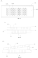
- FIG. 4 is a structural schematic view of a first substrate of the heating assembly shown in FIG. 3 , being viewed from a second surface.
- the heating assembly 11 includes a first substrate 111.
- the first substrate 111 has a first surface 1111 and a second surface 1112 opposite to the first surface 1111.
- the first surface 1111 is an atomizing surface.
- the first substrate 111 defines a plurality of first micro-pores 1113 extending from the first surface 1111 to the second surface 1112.
- the first micro-pores 1113 are configured to guide the aerosol generating substrate from the second surface 1112 to the first surface 1111.
- a cross section of each micro-pore 1113 is elongate-strip shaped.
- the cross section of the first micro-pore 1113 refers to a cross section perpendicular to an axial direction of the micro-pore 1113.
- the axial direction of the first micro-hole 1113 is parallel to a thickness direction of the first substrate 111.
- the first substrate 111 is sheet-shaped.
- the sheet shape is described relative to a block.
- a ratio of a length to a thickness of the sheet is greater than a ratio of a length to a thickness of the block.
- the first substrate 111 may be flat (as shown in FIG. 4 ), curved, cylindrical, and the like.
- other elements in the atomizer 1 are configured to match the structure of the first substrate 111.
- the length of the first substrate 111 refers to a length of an arc.
- the length of the first substrate 111 refers to a circumference length of the first substrate 111.
- the sheet-shaped heating assembly 11 in the present disclosure which defines the plurality of first micro-pores 1113, has a shorter liquid supply channel, and therefore, the liquid is supplied more quickly, it is ensured that sufficient liquid is supplied, and dry burning is avoided.
- the applicant has found the following.
- the first micro-pore 1113 is circular and the micro-pore has a diameter of 100 ⁇ m and more than 100 ⁇ m, shelf leakage may occur.
- the micro-pore has a diameter of greater than 45 ⁇ m, liquid splash during heating is likely to occur, such that the liquid is not atomized sufficiently, and the aerosol generating substrate may be wasted.
- the micro-pore When the micro-pore has a diameter of less than 20 ⁇ m, the amount of liquid supplied to the heating assembly is insufficient, resulting in serious accumulation of deposited scale. Moreover, the applicant also found that, when the first micro-pore 1113 is defined as an elongated-stripped hole, porosity of the first substrate 111 is improved, and sufficient amount of liquid can be supplied to the heating assembly, and the above problems occurred in the circular micro-pore are prevented.
- first micro-pore 1113 when the first micro-pore 1113 is circular, during an atomization process, air bubbles entering the first micro-pore 1113 grow longitudinally along a pore wall of the circular micro-pore, and the air bubbles are highly likely to attach to the second surface 1112 and to rush into the liquid storage cavity 14.
- the air bubbles grow transversely along the pore wall of the elongated micro-pore, and very few air bubbles may rush out of the first micro-pore 1113, such that air bubbles attaching to the second surface of the first substrate 111 is significantly reduced.
- the first substrate 111 is a porous substrate, such as a porous ceramic substrate, a cotton substrate, a substrate having a quartz sand core, or a substrate made from foam.
- a plurality of micro-pores in the first substrate 111 are the plurality of first micro-pores 1113, and the plurality of first micro-pores 1113 are disorganized through holes.
- the first substrate 111 is a dense substrate, such as a quartz substrate, a glass substrate, a dense ceramic substrate, or a silicon substrate.
- Each first micro-pore 1113 is a through-hole that extends from the first surface 1111 to the second surface 1112.
- the plurality of first micro-pores 1113 are through holes arranged in an order.
- the glass substrate it may be made of any one of: ordinary glass, quartz glass, borosilicate glass, and photosensitive lithium aluminum silicate glass.
- the first substrate 111 When the first substrate 111 is the dense substrate, it is easily to perform a micro-machining treatment on the dense substrate, and the plurality of first micro-pores 1113 formed in the first substrate 111 may have a substantially the same size.
- the porosity of the heating assembly 11 may be precisely controlled, such that consistency of products is improved. That is, in mass production, first substrates 111 of heating assemblies 11 may have a consistent porosity, such that electronic atomizing devices that are produced from a same batch may have a same atomizing effect.
- FIG. 5 is a schematic view of the first micro-pore contacting the aerosol generating substrate when a surface of the first micro-pore being rough; and FIG. 6 is a schematic view of a second micro-pore contacting the aerosol generating substrate when a surface of the second micro-pore being smooth.
- a surface of each first micro-pore 1113 defined in the first substrate 111 is relatively rough. That is, the surface of the first micro-pore 1113 is relatively coarse.
- the aerosol generating substrate in the first micro-pore 1113 may flow, through the rough surface, to an exterior of the micro-pore, and an outwardly convex liquid film (as shown in FIG. 5 ) may be formed at a port of the first micro-pore 1113. In this way, liquid leakage may occur easily.
- the surface of the first micro-pore 1113 defined in the first substrate 111 is smooth, a contact angle between the aerosol generating substrate and the surface of the first micro-pore 1113 is less than 90 degrees.
- a liquid surface formed by the aerosol generating substrate inside the first micro-pore 1113 is inwardly concave (as shown in FIG. 6 ), such that the liquid leakage is prevented.
- the first substrate 111 is the dense substrate and the first micro-pores 1113 are elongated-stripped pores, a larger liquid flowing area is provided, and liquid leakage is prevented.
- the first micro-pores 1113 are straight through holes. Specifically, an axis of each first micro-pore 1113 is parallel to the thickness direction of the first substrate 111.
- the plurality of first micro-pores 1113 are arranged in an array. Specifically, the plurality of first micro-pores 1113 are arranged in a two-dimensional array.
- the plurality of first micro-pores 1113 are arranged into a plurality of rows and a plurality of columns. Every two adjacent rows of the plurality of rows have an equal row-spacing; and every two adjacent columns of the plurality of columns have an equal column-spacing. It is understood that the arrangement of the plurality of first micro-pores 1113 may be determined based on demands, which will not be limited herein.
- a width of each first micro-pore 1113 is less than or equal to 100 ⁇ m, and/or a ratio of a length to a width of the first micro-pore 1113 is greater than 1.5.
- the width of the first micro-pore 1113 is greater than 100 ⁇ m, the aerosol generating substrate may be easily flow out of the first micro-pore 1113, resulting in the liquid leakage, leading to a poor usage experience.
- the ratio of the length to the width of the first micro-pore 1113 is less than 1.5, a boundary restriction of the first micro-pore 1113 is not sufficient to enable the air bubbles to grow transversely along the pore wall of the first micro-pore 1113.
- the width of the first micro-pore 1113 is 20 ⁇ m-45 ⁇ m, and/or the ratio of the length to the width of the first micro-pore 1113 is greater than 1.5.
- the air bubbles grow transversely along the pore wall of the first micro-pore 1113, such that the air bubbles may not flow reversely into the liquid storage cavity 14. In this way, the atomizing efficiency is improved, and dry burning or film disruption, which is caused by the air bubbles flowing reversely (i.e., flowing into the liquid storage cavity 14), may be reduced.
- the film disruption refers to a heating element 112 being broken, which will be described in the following.
- the ratio of the length to the width of the first micro-pore 1113 is greater than 3.
- the heating assembly 11 further includes a heating element 112, a positive electrode 113 and a negative electrode 114. Two ends of the heating element 112 are electrically connected to the positive electrode 113 and the negative electrode 114, respectively.
- the heating element 112 is disposed on the first surface 1111 of the first substrate 111 to atomize the aerosol generating substrate to generate the aerosol. Both the positive electrode 113 and the negative electrode 114 are disposed on the first surface 1111 of the first substrate 111 to be electrically connected to the host portion 2.
- the heating element 112 may be a heating sheet, a heating film, a heating mesh, and so on, as long as the heating element 112 can heat and atomize the aerosol generating substrate.
- the heating element 112 may be embedded inside the first substrate 111.
- at least a portion of the first substrate 111 is electrically conductive, and when the first substrate 111 is conducted, the first substrate 111 heats and atomizes the aerosol generating substrate, i.e., the first substrate 111 atomizes the aerosol generating substrate and guides the liquid simultaneously.
- Material of the heating element 112 is not limited herein. Distribution of heat flow density of the heating element 112 may be controlled according to shapes and sizes of the first micro-pores 1113, which may be determined based on demands.
- the elongated-stripped pores are anisotropic.
- a resistance of the heating element 112 may be achieved by regulating a direction of a current (the shape of the heating element 112) and the arrangement of the elongated-stripped pores. In other words, a reasonable combination of the elongated-stripped pores and the heating element 112 allows the heating element 112 to be made of various materials.
- the applicant also conducted experiments to compare the circular pores and elongated-stripped pores.
- An atomization consumption of the elongated-stripped pore (a ratio of the amount of atomization to a power consumption) is relatively large, an energy utilization rate of the elongated-stripped pore is higher.
- the atomization consumption of the elongated-stripped pore may be 1.56, and an atomization consumption of the circular pore may be 1.3.
- the heating element 112 may be a heating film made of a 316 stainless steel and has a power of 6.5W.
- the aerosol generating substrate is coke ice.
- FIG. 7 is a structural schematic view of the heating assembly according to a second embodiment of the present disclosure
- FIG. 8 is an enlarged view of a portion of the first substrate of the heating assembly shown in FIG. 7 , being viewed from the second surface
- FIG. 9 is a structural schematic view of the first substrate of the heating assembly shown in FIG. 7 , being viewed from the first surface
- FIG. 10 is an enlarged view of a portion shown in FIG. 9 .
- a structure of the heating assembly 11 in the second embodiment is substantially the same as the structure of the heating assembly 11 in the first embodiment.
- the first surface 1111 of the first substrate 111 is arranged with a groove portion 1114 communicated with the plurality of first micro-pores 1113. Similar structures will not be repeated herein.
- the groove portion 1114 includes a plurality of first grooves 1114a extending in a first direction and a plurality of second grooves 1114b extending in a second direction.
- the plurality of first grooves 1114a intersect with the plurality of second grooves 1114b.
- the aerosol generating substrate may flow transversely due to the first grooves 1114a and the second grooves 1114b enabling the plurality of first micro-pores 1113 to be communicated with each other. In this way, the aerosol generating substrate may be further supplied to a segment of the blocked first micro-pore 1113 near the first surface 1111, such that dry burning is avoided.
- the transverse refers to a direction that is not parallel to an extending direction of the first micro-pore 1113, such as a direction perpendicular to the axis of the first micro-pore 1113.
- the length direction of the first micro-pore 1113 is parallel to the first direction, and at least a portion of the first micro-pore 1113 is disposed at an intersection between the first groove 1114a and the second groove 1114b.
- One first micro-pore 1113 extends from one second groove 1114b to another second groove 114b.
- first grooves 1114a extending in the first direction are defined, or only the plurality of second grooves 1114b extending in the second direction are defined. That is, adjacent first micro-pores 1113 are communicated with each other in only one direction.
- the plurality of first grooves 1114a extending in the first direction and/or the plurality of second grooves 1114b extending in the second direction have a capillary effect, such that the aerosol generating substrate can be guided to flow in the transverse direction, and the aerosol generating substrate can be supplied in the transverse direction.
- the heating element 112 is the heating film made from the 316 stainless steel.
- the heating element 112 is double 2x1 films and has a power of 6.5W
- the aerosol generating substrate is coke ice
- the first micro-pores 1113 are elongated-stripped pores (each elongated-stripped pore has a width of 28 ⁇ m and a length of 150 ⁇ m).
- the experiments are repeated for three times, obtaining the amount of atomization of 9.9 mg, 9.7 mg, and 9.6 mg, respectively.
- the amount of atomization of the circular pore is approximately 7.7 mg.
- material of the substrate 111 having the elongate pores is the same as material of the substrate having the circular pores.
- the first surface 1111 of the substrate 111 having the elongate pores is arranged with the groove portion 1114, and the first surface of the substrate having the circular pores is also arranged with the groove portion.
- Data of the first surface 1111 having the groove portion 1114 are compared to data of the first surface 1111 that does not define the groove portion 1114 (the amount of atomization in the three experiments are 8.4 mg, 8.3 mg, and 8.1 mg, respectively), and it is found that arranging the groove portion 1114 in the first surface 1111 enables the amount of atomization to be increased.
- FIG. 11 is a structural schematic view of the heating assembly according to a third embodiment of the present disclosure
- FIG. 12 is a cross-sectional view of the heating assembly shown in FIG. 11
- FIG. 13 is a structural schematic view of the heating assembly shown in FIG. 11 , being viewed from a liquid absorbing surface.
- the heating assembly 11 in the third embodiment is different from the heating assembly 11 in the first embodiment.
- the heating assembly 11 in the third embodiment further includes a second substrate 115, disposed on a side of the first substrate 111 near the liquid storage cavity 14.
- the second substrate 115 includes a third surface 1151 and a fourth surface 1152 opposite to the third surface 1151.
- the fourth surface 1152 is a liquid absorbing surface.
- the second substrate 115 defines a plurality of second micro-pores 1153 extending from the third surface 1151 to the fourth surface 1152.
- the second micro-pores 1153 are configured to guide the aerosol generating substrate to flow from the fourth surface 1152 to the third surface 1151. That is, the second micro-pores 1153 are configured to guide the aerosol generating substrate to flow from the liquid absorbing surface to the third surface 1151.
- the second micro-pores 1153 and the first micro-pores 1113 are communicated with each other.
- the third surface 1151 of the second substrate 115 faces towards the second surface 1112 of the first substrate 111. It is understood that the aerosol generating substrate in the liquid storage cavity 14 flows, through the liquid supplying channel 1211, to the fourth surface 1152 of the second substrate 115.
- the second micro-pores 1153 takes the capillary force to guide the aerosol generating substrate to flow to reach the third surface 1151 of the second substrate 115
- the first micro-pores 1113 takes the capillary force to guide the aerosol generating substrate to flow from the first surface 1111 of the first substrate 111 to the second surface 1112 of the first substrate 111.
- the aerosol generating substrate flows from the fourth surface 1152 of the second substrate 115, through the second micro-pores 1153 and the first micro-pores 1113, to reach the first surface 1111 of the first substrate 111.
- the aerosol generating substrate flows from the liquid absorbing surface to the atomizing surface under the gravitational force and/or the capillary force.
- the aerosol generating substrate is heated and atomized to generate the aerosol at the atomizing surface of the heating assembly 11.
- the capillary force of the first micro-pores 1113 is greater than the capillary force of the second micro-pores 1153 to allow the aerosol generating substrate to flow from the liquid absorbing surface to the atomizing surface.
- a projection of the second substrate 115 onto the first substrate 111 completely covers the heating element 112.
- the heating element 112 is heating, a region of the first substrate 111 where the heating element 112 is located and another region adjacent thereto have temperatures that can atomize the aerosol generating substrate to generate the aerosol. Therefore, the region of the first substrate 111 where the heating element 112 is located and the another region adjacent thereto are defined as an atomizing region. That is, the first substrate 111 includes the atomizing region (not labeled in the drawing) in which the aerosol generating substrate is atomized to generate the aerosol. At least the atomizing region of the first substrate 111 defines the plurality of first micro-pores 1113.
- a region of the second substrate 115 that defines the plurality of second micro-pores 1153 covers at least the atomizing region of the first substrate 111, such that a liquid supplying rate satisfies an atomization rate of the heating element 112, and a better atomizing effect can be achieved.
- the second substrate 115 may insulate heat to a certain extent, preventing heat of the first substrate 111 from being transferred to the liquid storage cavity 14, such that the taste of the aerosol may be consistent.
- the air bubbles from the first micro-pores 1113 of the first substrate 111 may attach to the second surface 1112 of the first substrate 111.
- the second substrate 115 may prevent the air bubbles from growing up, and the air bubbles are prevented from blocking the first micro-pores 1113 and/or the second micro-pores 1153.
- the second micro-pores 1153 also have the capillary force, when the port of the aerosol outlet channel 13 is facing downwardly, the liquid can be prevented from flowing reversely, and sufficient amount of liquid may be supplied .
- the second substrate 115 is a sheet-shaped substrate.
- the sheet shape is described relative to a block.
- a ratio of the length to the thickness of the sheet is greater than a ratio of the length to the thickness of the block.
- the second substrate 115 may be flat (as shown in FIG. 12 ), curved, cylindrical, and the like.
- the shape of the second substrate 115 is fit with the shape of the first substrate 111.
- the length refers to a length of the arc.
- the length refers to a circumference of the first substrate 111.
- the second substrate 115 is a porous substrate, such as a porous ceramic substrate, a cotton substrate, a substrate having a quartz sand core, or a substrate made from foam.
- a plurality of micro-pores in the second substrate 115 are the plurality of first micro-pores 1113, and the plurality of first micro-pores 1113 are disorganized through holes.
- the second substrate 115 is a dense substrate, such as a quartz substrate, a glass substrate, a dense ceramic substrate, or a silicon substrate.
- Each second micro-pore 1153 is a through hole that extends from the first surface 1111 to the second surface 1112.
- the plurality of second micro-pores 1153 are through holes arranged in an order.
- the glass substrate it may be made of any one of: ordinary glass, quartz glass, borosilicate glass, and photosensitive lithium aluminum silicate glass.
- the first substrate 111 and the second substrate 115 may be made of a same material or different materials.
- the first substrate 111 and the second substrate 115 may be combined with each other in any manner.
- the first substrate 111 may be the porous substrate, and the second substrate 115 may be the dense substrate.
- the first substrate 111 may be the porous substrate, and the second substrate 115 may be the porous substrate.
- the first substrate 111 may be the dense substrate, and the second substrate 115 may be the porous substrate.
- the first substrate 111 may be the dense substrate, and the second substrate 115 may be the dense substrate.
- the first substrate 111 is the dense substrate, and the second substrate 115 is the dense substrate.
- the second micro-pores 1153 are straight through holes. Specifically, an axis of each second micro-pore 1153 is parallel to a thickness direction of the second substrate 115.
- the plurality of second micro-pores 1153 are arranged in an array. Specifically, the plurality of second micro-pores 1153 are arranged in a plurality of columns. Every two adjacent columns of the plurality of columns have an equal column-spacing. Second micro-pores 1153 of two adjacent columns are misaligned with each other. Every two adjacent second micro-pores 1153 in each column have an equal pore-spacing. It is understood that the arrangement of the plurality of second micro-pores 1153 may be determined based on demands, which will not be limited herein.
- the thickness of the second substrate 115 is 0.2 mm-1 mm.
- the second substrate 115 may not provide an effective blocking effect on the air bubbles, and the air bubbles may easily flow reversely (flow into the liquid storage cavity 14), and noise may be generated when the air bubbles are flowing flow reversely.
- the thickness of the second substrate 115 is greater than 1 mm, the air bubbles may be easily stuck in the second micro-pore 1153, such that the amount of liquid supplied to the heating assembly is insufficient, and serious accumulation of deposited scale may be caused.
- a cross section of the second micro-pore 1153 is circular.
- the cross section of the second micro-pore 1153 refers to a cross section perpendicular to the axis direction of the second micro-pore 1153.
- the cross section of the second micro-pore 1153 is elongated-strip shaped (as shown in FIGS. 11 and 13 ).
- a width of the second micro-pore 1153 is 10 ⁇ m-160 ⁇ m, and/or a length of the second micro-pore 1153 is not less than 100 ⁇ m.
- the width of the second micro-pore 1153 is less than 10 ⁇ m, the liquid flowing may be affected, an insufficient amount of liquid may be supplied, and dry burning may be caused.
- the width of the second micro-pore 1153 is greater than 160 ⁇ m, growth of the air bubbles cannot be restricted effectively, and therefore, the air bubbles may grow to large sizes and block the second micro-pore 1153, the liquid flowing may be affected, and an insufficient amount of liquid may be supplied.
- the length of the second micro-pore 1153 is less than 100 ⁇ m, the air bubbles may block the second micro-pore 1153, the liquid flowing may be affected, and an insufficient amount of liquid may be supplied.
- the length of the second micro-pore 1153 is not less than 300 ⁇ m.
- a projection of one second micro-pore 1153 on the first substrate 111 covers at least a portion of each of the plurality of first micro-pores 1113; and/or a length direction of the first micro-pore 1113 intersects with a length direction of the second micro-pore 1153 (as shown in FIG. 13 ).
- the second substrate 115 is rectangular, and the length direction of the second micro-pore 1153 is perpendicular to the length direction of the second substrate 115.
- the second substrate 115 may supply a large amount of liquid to ensure sufficient amount of liquid to be supplied to be heated, and dry burning is avoided.
- the length direction of the first micro-pore 1113 intersects with the length direction of the second micro-pore 1153, an overlapping rate between the first micro-pores 1113 and the second micro-pores 1153 may be increased, and that is, a probability that the first micro-pores 1113 are directly communicated to the second micro-pores 1153 is increased.
- the length direction of the first micro-pore 1113 is perpendicular to the length direction of the second micro-pore 1153.
- One second micro-pore 1153 exposes five or six first micro-pores 1113.
- the second surface 1112 of the first substrate 111 is attached with the third surface 1151 of the second substrate 115 (as shown in FIG. 12 ).
- the projection of the second micro-pore 1153 on the first substrate 111 covers at least a portion of the plurality of first micro-pores 1113 (as shown in FIG. 13 ) to allow the aerosol generating substrate to flow from the second micro-pore 1153, through the portion where the second micro-pore 1153 overlaps with the first micro-pore 1113, to the first micro-pore 1113.
- the second surface 1112 is parallel with the third surface 1151.
- the second surface 1112 of the first substrate 111 defines a plurality of micro-slots (not shown in the drawing).
- the plurality of micro-slots enable the plurality of first micro-pores 1113 to be communicated with each other, such that the aerosol generating substrate, which is located in a region having a sufficient amount of liquid to be supplied, can be guided to flow to a region that receives insufficient amount of liquid to be supplied.
- a width of the micro-slot is in a range from 5 ⁇ m to 500 ⁇ m. In an embodiment, the width of the micro-slot is in a range from 10 ⁇ m to 100 ⁇ m.
- the second surface 1112 of the first substrate 111 is attached to the third surface 1151 of the second substrate 115, the second surface 1112 defines the plurality of micro-slots to cause a gap (not shown in the drawings) to be formed between the second surface 1112 and the third surface 1151. That is, the first substrate 111 and the second substrate 115 are laminated on each other. The second surface 1112 is attached to the third surface 1151, and a gap is defined between the second surface 1112 and the third surface 1151.
- FIG. 14 is a structural schematic view of another relative position between the first substrate and the second substrate of the heating assembly shown in FIG. 11 .
- a gap 116 is defined between the second surface 1112 of the first substrate 111 and the third surface 1151 of the second substrate 115.
- the gap 116 communicates the first micro-pores 1113 with the second micro-pores 1153.
- the gap 116 has a uniform height. That is, the first substrate 111 is laminated on the second substrate 115, the first substrate 111 is parallel to and spaced apart from the second substrate 115, and the second surface 1112 is parallel to the third surface 1151, such that the gap 116 is defined between the second surface 1112 and the third surface 1151.
- the heating assembly 11 further includes a spacing member 117.
- the spacing member 117 is disposed between the second surface 1112 and the third surface 1151 and is disposed at an edge of the first substrate 111 and/or an edge of the second substrate 115, to define the gap 116 between the first substrate 111 and the second substrate 115.
- the liquid may be replenished in the transverse direction. Even when the air bubbles are attached to the fourth surface 1152 (i.e., the liquid absorbing surface) of the second substrate 115 to cover part of the second micro-pores 1153, supplying the fluid to the first substrate 111 is not affected. Furthermore, by defining the gap 116, a range in which the air bubbles can grow is limited, any air bubble located out of the first micro-pore 1113 may not be formed easily. When the air bubbles are collapsed, the liquid is discharged from the atomizing surface, such that large sized air bubbles are prevented from attaching to the liquid absorbing surface of the second substrate 115 to affect the liquid supplying, and therefore, dry burning is avoided.
- FIG. 15 is a structural schematic view of still another relative position between the first substrate and the second substrate of the heating assembly shown in FIG. 11 .
- the gap 116 is formed between the second surface 1112 of the first substrate 111 and the third surface 1151 of the second substrate 115, and the gap 116 communicates the first micro-pores 1113 with the second micro-pores 1153.
- the first substrate 111 and the second substrate 115 are laminated on each other.
- the second surface 1112 is non-parallel with the third surface 1151.
- the height of the gap 116 varies gradually, and specifically, the height of the gap 116 gradually increases, or the height of the gap 116 gradually decreases and then gradually increases.
- the capillary force formed by the gap 116 also varies gradually to drive the aerosol generating substrate to flow in the gap 116. That is, the air bubbles in the gap 116 are enabled to flow, such that the air bubbles in the gap 116 cannot be staying stably and cannot be stuck. In this way, the air bubbles are facilitated to be discharged from the second micro-pores 1153, and the air bubbles are prevented from retaining in the gap 116 to block the port of the second micro-pore 1153 near the first substrate 111, ensuring a sufficient amount of liquid to be supplied to the heating element, and preventing dry burning.
- the spacing member 117 is disposed at an edge of an end of the first substrate 111 and an edge of an end of the second substrate 115. An edge of the other end of the first substrate 111 abuts against an edge of the other end of the second substrate 115.
- two spacing members 117 are disposed respectively at the edges of two ends of the first substrate 111 and the edges of two ends of the second substrate 115, and the two spacing members 117 have different heights.
- groove portion 1114 arranged in the first surface 1111 of the first substrate 111 in the second embodiment of the heating assembly 11 may be applied to the heating assembly 11 in the third embodiment, and a similar technical effect can be achieved.
- FIG. 16 is a structural schematic view of the heating assembly according to a fourth embodiment of the present disclosure
- FIG. 17 is a structural schematic view of the heating assembly shown in FIG. 16 , being viewed from the liquid absorbing surface
- FIG. 18 is a structural schematic view of the heating assembly shown in FIG. 16 , being viewed from the atomizing surface.
- the heating assembly 11 in the fourth embodiment is different the heating assembly 11 in the third embodiment.
- the cross section of the first micro-pore 1113 is elongated-strip shaped
- the cross section of the second micro-pore 1153 is circular or elongated-strip shaped.
- the cross section of the first micro-pore 1113 is circular
- the cross section of the second micro-pore 1153 is elongated-strip shaped.
- the heating assembly 11 in the fourth embodiment is substantially the same as the heating assembly 11 in the third embodiment, and the same structures will not be repeated herein.
- the second micro-pore 1153 of the second substrate 115 by defining the second micro-pore 1153 of the second substrate 115 to be the elongated-stripped pore, a speed of supplying the liquid is satisfied, and at the same time, the air bubbles are prevented from flowing reversely (i.e., flowing into the liquid storage cavity 14).
- a speed of supplying the liquid is satisfied, and at the same time, the air bubbles are prevented from flowing reversely (i.e., flowing into the liquid storage cavity 14).
- a larger resistance is applied to the growth of the air bubbles, such that the air bubbles may not fulfill the entire elongated-stripped pore, and the air bubbles are prevented from blocking the second micro-pore 1153, a sufficient amount of liquid can be supplied to the heating element.
- the air bubbles may grow transversely along a pore wall of the second micro-pore 1153, such that the air bubbles cannot flow reversely to enter the liquid storage cavity 14. In this way, the atomizing efficiency is improved, and dry burning or film disruption, caused by the air bubbles flowing reversely, is reduced.
- the width of the second micro-pore 1153 is not less than a diameter of the first micro-pore 1113, enabling the aerosol generating substrate to flow from the second micro-pore 1153 to the first micro-pore 1113 to be atomized by the heating element 112.
- the projection of one second micro-pore 1153 on the first substrate 111 covers at least a portion of each of the plurality of first micro-pores 1113 (as shown in FIG. 17 ), such that a sufficient amount of fluid is supplied, and dry burning is avoided.
- the diameter of the first micro-pore 1113 is 5 ⁇ m-120 ⁇ m.
- the diameter of the first micro-pore 1113 is less than 5 ⁇ m, the speed of supplying the liquid to the heating element cannot satisfy the atomization demand of the heating element 112, resulting in a decrease in the amount of generated aerosol.
- the diameter of the first micro-pore 1113 is greater than 120 ⁇ m, the aerosol generating substrate may flow out of the first micro-pore 1113, resulting in liquid leakage. It is understood that the diameter of the first micro-pore 1113 is determined according to demands in practice.
- the width of the second micro-pore 1153 is 10 ⁇ m-160 ⁇ m.
- the width of the second micro-pore 1153 is less than 10 ⁇ m, the liquid supplying is affected, an insufficient amount of liquid may be supplied, resulting in dry burning.
- the width of the second micro-pore 1153 is greater than 160 ⁇ m, growth of the air bubbles may not be restricted effectively, and the air bubbles may grow to large sizes to block the second micro-pore 1153, such that the liquid supplying is affected, and an insufficient amount of liquid may be supplied.
- the length of the second micro-pore 1153 is not less than 100 ⁇ m.
- the air bubbles may block the second micro-pore 1153, blocking the liquid from flowing, resulting in an insufficient amount of liquid to be supplied to the heating element.
- the length of the second micro-pore 1153 is not less than 300 ⁇ m.
- a spacing between two adjacent second micro-pore 1153 is not equal to an integer multiple of the diameter of the first micro-pore 1113.
- a rate of alignment between the second micro-pores 1153 and the first micro-pores 1113 may be increased, and an influence in the rate of alignment between the second micro-pores 1153 and the first micro-pores 1113, caused by an assembly tolerance, may be reduced.
- a deviation between a principle value and the rate of alignment between the second micro-pores 1153 and the first micro-pores 1113 of actual assembling may be reduced. Performance of the heating assembly 11 is ensured, and consistency of heating assemblies 11 in mass production is improved.
- the second substrate 115 is rectangular, and the length direction of the second micro-pore 1153 is parallel to the length direction of the second substrate 115. Compared to the length direction of the second micro-pore 1153 being perpendicular to the length direction of the second substrate 115, the instant configuration allows the second substrate 115 to have higher strength.
- the thickness of the second substrate 115 is 0.2 mm-1 mm.
- the air bubbles may not be blocked effectively, the air bubbles may flow reversely (flow into the liquid storage cavity 14), and large noise may be generated when the air bubbles are flowing reversely.
- the thickness of the second substrate 115 is greater than 1 mm, the air bubbles may be easily stuck in the second micro-pore 1153, an insufficient amount of liquid may be supplied, and serious accumulation of deposited scale may be caused.
- the second surface 1112 of the first substrate 111 defines a plurality of micro-slots (not shown), and the plurality of micro-slots are communicated with the first micro-pores 1113.
- the aerosol generating substrate which is located in a region having a sufficient amount of liquid to be supplied, can be guided to flow to a region that receives insufficient amount of liquid to be supplied.
- a width of the micro-slot is in a range of 5 ⁇ m to 500 ⁇ m. In an embodiment, the width of the micro-slot is in a range of 10 ⁇ m to 100 ⁇ m.
- the first substrate 111 and the second substrate 115 are laminated on each other.
- the second surface 1112 of the first substrate 111 is opposite to the third surface 1151 of the second substrate 115.
- the second surface 1112 and the third surface 1151 may be attached to or spaced apart from each other; and the second surface 1112 and the third surface 1151 may be parallel or non-parallel to each other.
- the gap 116 is defined between the second surface 1112 of the first substrate 111 and the third surface 1151 of the second substrate 115 and is communicated with the first micro-pores 1113 and the second micro-pores 1153.
- first substrate 111 and the second substrate 115 are laminated on each other.
- the second surface 1112 is attached to the third surface 1151.
- the second surface 1112 is parallel to the third surface 1151.
- the gap is defined between the second surface 1112 and the third surface 1151 (not shown in the drawing).
- first substrate 111 and the second substrate 115 are laminated on each other.
- the second surface 1112 and the third surface 1151 are spaced apart from and parallel to each other. In this way, the gap 116 between the second surface 1112 and the third surface 1151 (referred to the description for FIG. 14 ) is defined.
- first substrate 111 and the second substrate 115 are laminated on each other, the second surface 1112 and the third surface 1151 are non-parallel to each other, and the gap 116 is defined between the second surface 1112 and the third surface 1151 (refer to the description for FIG. 15 ).
Landscapes
- Special Spraying Apparatus (AREA)
- Resistance Heating (AREA)
- Nozzles (AREA)
- Fuel-Injection Apparatus (AREA)
Abstract
Description
- The present disclosure relates to the field of atomization, and in particular to a heating assembly, an atomizer, and an electronic atomizing device.
- An electronic atomizing device includes a heating body, a battery, a control circuit, and so on. The heating body serves as a core element of the electronic atomizing device, and properties of the heating body determines an atomizing effect and usage experience of the electronic atomizing device.
- In the art, the heating body has a cotton core. Usually, the cotton-core heating body is a spring-like metal heating wire that wraps around a cotton rope or a fiber rope. A to-be-atomized aerosol generating substrate, which is in a liquid phase, is absorbed by two ends of the cotton rope or the fiber rope and is then transferred to a center where the metal heating wire is arranged to be heated and atomized by the metal heating wire. Since the ends of the cotton rope or the fiber rope have limited area, the aerosol generating substrate may be adsorbed and transferred less efficiently, and therefore, insufficient liquid may be supplied, and dry burning may occur.
- In the art, the heating body may be a ceramic heating body. Usually, for the ceramic heating body, a metal heating film is formed on a surface of a porous ceramic body. The porous ceramic body may guide and store liquid. The metal heating film heats and atomizes the liquid aerosol generation substrate. However, it is difficult to precisely control distribution and dimension of pores of the porous ceramic body, which is prepared by high-temperature sintering. In order to reduce a risk of liquid leakage, a pore size and porosity need to be reduced. However, in order to supply sufficient amount of liquid, the pore size and the porosity need to be increased. Therefore, the requirements are conflicting to each other. Currently, when the pore size and the porosity enables the risk of liquid leakage to be low, liquid conductivity of the porous ceramic body is limited. In this case, when a high power is applied, a burnt flavor occurs.
- The present disclosure provides a heating assembly, an atomizer, and an electronic atomizing device, to solve the problem that the heating body does not supply sufficient amount of liquid.
- In a first aspect, a heating assembly is provided. The heating assembly is configured for an electronic atomizing device to atomize an aerosol generating substrate. The heating assembly includes: a first substrate, having a first surface and a second surface opposite to the first surface; wherein the first surface is an atomizing surface; the first substrate defines a plurality of first micro-pores extending from the first surface to the second surface; the plurality of first micro-pores are configured to guide the aerosol generating substrate to flow from the second surface to the first surface; a cross section of each first micro-pore is elongated-strip shaped.
- In some embodiments, the first substrate is a dense substrate, an axis of the first micro-pore is parallel to a thickness direction of the first substrate, the plurality of the first micro-pores are arranged in an array.
- In some embodiments, a width of each first micro-pore is less than or equal to 100 µm; and/or a ratio of a length to the width of each first micro-pore is greater than 1.5.
- In some embodiments, the width of each first micro-pore is 20 µm to 45 µm; and/or the ratio of the length to the width of each first micro-pore is greater than 1.5.
- In some embodiments, the heating assembly further includes: a heating element, wherein, the heating element is disposed on the first surface of the first substrate and is configured to atomize the aerosol generating substrate.
- Alternatively, the first substrate is at least partially electrically conductive and is configured to heat and atomize, when the first substrate being conducted, the aerosol generating substrate.
- In some embodiments, the first surface is arranged with a groove portion, the groove portion is communicated with the plurality of the first micro-pores.
- In some embodiments, the groove portion comprises a plurality of first grooves extending in a first direction and a plurality of second grooves extending in a second direction, the plurality of first grooves intersect with the plurality of second grooves.
- A length direction of the first micro-pore is parallel to the first direction; at least a portion of the first micro-pore is located at an intersection between one of the plurality of first grooves and a corresponding one of the plurality of second grooves.
- In some embodiments, each first micro-pore extends from one of the plurality of second grooves to another one of the plurality of second grooves.
- In a second aspect, a heating assembly is provided. The heating assembly is configured for an electronic atomizing device to atomize an aerosol generating substrate. The heating assembly includes: a first substrate, having a first surface and a second surface opposite to the first surface; wherein, the first surface is an atomizing surface; the first substrate defines a plurality of first micro-pores extending from the first surface to the second surface; a second substrate, having a third surface and a fourth surface opposite to the third surface; wherein, the fourth surface is a liquid absorbing surface; the third surface faces towards the second surface; the second substrate defines a plurality of second micro-pores extending from the third surface to the fourth surface. A cross section of each first micro-pore and/or each second micro-pore is elongated-strip shaped; the aerosol generating substrate is capable of flowing from the fourth surface of the second substrate, through at least one of the plurality of first micro-pores and at least one of the plurality of second micro-pores, to the first surface of the first substrate.
- In some embodiments, a cross section of each first micro-pore is circular; and a cross section of each second micro-pore is elongated-strip shaped.
- In some embodiments, a width of the second micro-pore is not less than a diameter of the first micro-pore.
- In some embodiments, the diameter of the first micro-pore is 5µm to 120µm, and the width of the second micro-pore is 10µm to 160µm.
- In some embodiments, a length of the second micro-pore is not less than 100 µm.
- In some embodiments, along a width direction of the second micro-pore, a spacing between two adjacent second micro-pores of the plurality of second micro-pores is not equal to an integer multiple of the diameter of the first micro-pore.
- In some embodiments, the second substrate is rectangular, a length direction of the second micro-pore is parallel to a length direction of the second substrate.
- In some embodiments, the thickness of the second substrate is 0.2mm to 1mm.
- In some embodiments, a cross section of each first micro-pore is elongated-strip shaped, and a cross section of each second micro-pore is circular.
- In some embodiments, a cross section of each first micro-pore is elongated-strip shaped, and a cross section of each second micro-pore is elongated-strip shaped.
- In some embodiments, a width of each first micro-pore is less than or equal to 100 µm; and/or a ratio of a length to the width of each first micro-pore is greater than 1.5.
- In some embodiments, a width of each second micro-pore is 10µm to 160µm; and/or a length of each second micro-pore is not less than 100µm.
- In some embodiments, a projection of one of the plurality of second micro-pores on the first substrate covers at least a portion of each of the plurality of first micro-pores; and/or the length direction of the first micro-pores intersects with the length direction of the second micro-pores.
- In some embodiments, the first surface of the first substrate is arranged with a groove portion, and the groove portion is communicated with the plurality of first micro-pores.
- In some embodiments, the first substrate comprises an atomizing region in which the aerosol generating substrate is atomized to generate an aerosol; and the plurality of first micro-pores are disposed in the atomizing region.
- A region of the second substrate in which the plurality of second micro-pores are disposed covers at least the atomizing region of the first substrate.
- In some embodiments, the heating assembly further includes a heating element. The heating element is disposed on the first surface of the first substrate and configured to atomize the aerosol generating substrate.
- Alternatively, at least a portion of the first substrate is electrically conductive and is configured to heat and atomize the aerosol generating substrate when the portion of the first substrate being conducted.
- In some embodiments, the first substrate and the second substrate are laminated on each other, and a gap is formed between the second surface of the first substrate and the third surface of the second substrate.
- The second surface of the first substrate is attached to or spaced apart from the third surface of the second substrate.
- The second surface of the first substrate is parallel or non-parallel to the third surface of the second substrate.
- In some embodiments, the first substrate is a dense substrate, an axis of each first micro-pore is parallel to the thickness direction of the first substrate, and the plurality of the first micro-pores are arranged in an array; and/or
- The second substrate is a dense substrate, an axis of each second micro-pore is parallel to the thickness direction of the second substrate; the plurality of second micro-pores are arranged in an array.
- In a third aspect, an atomizer is provided and includes: a liquid storage cavity, configured to store an aerosol generating substrate; and the heating assembly according to any of the above aspects. The heating assembly is fluidly connected with the liquid storage cavity, the heating assembly is configured to atomize the aerosol generating substrate.
- In a fourth aspect, an electronic atomizing device is provided and includes: the atomizer in the above aspect and a host portion, configured to provide electrical power to the atomizer to operate and to control the heating assembly to atomize the aerosol generating substrate.
- According to the present disclosure, a heating assembly, an atomizer, and an electronic atomizing device are provided. The heating assembly includes a first substrate. The first substrate has a first surface and a second surface opposite to the first surface. The first surface is an atomizing surface. The first substrate defines a plurality of first micro-pores that extend through the first surface and the second surface. The first micro-pores are configured to guide the aerosol generating substrate to flow from the second surface to the first surface. A cross section of each first micro-pore is elongated-strip shaped. By defining the first micro-pore to have the elongated-strip shape, the amount of transferred liquid is increased to ensure sufficient liquid to be supplied; and air is prevented from flowing reversely, and bubbles are prevented from being stuck in the liquid.
- In order to more clearly illustrate the technical solutions in the embodiments of the present disclosure or in the related art, the accompanying drawings for describing the embodiments or the related art will be introduced briefly in the following. Apparently, the following description of the accompanying drawings shows only some of the embodiments of the present disclosure. Any ordinary skilled person in the art may obtain other accompanying drawings based on the accompanying drawings without any creative work.
-
FIG. 1 is a structural schematic view of an electronic atomizing device according to an embodiment of the present disclosure. -
FIG. 2 is a structural schematic view of an atomizer of the electronic atomizing device shown inFIG. 1 . -
FIG. 3 is a structural schematic view of a heating assembly according to a first embodiment of the present disclosure. -
FIG. 4 is a structural schematic view of a first substrate of the heating assembly shown inFIG. 3 , being viewed from a second surface. -
FIG. 5 is a schematic view of a first micro-pore contacting an aerosol generating substrate when a surface of the first micro-pore being rough. -
FIG. 6 is a schematic view of a second micro-pore contacting the aerosol generating substrate when a surface of the second micro-pore being smooth. -
FIG. 7 is a structural schematic view of a heating assembly according to a second embodiment of the present disclosure. -
FIG. 8 is an enlarged view of a portion of a first substrate of the heating assembly shown inFIG. 7 , being viewed from a second surface. -
FIG. 9 is a structural schematic view of the first substrate of the heating assembly shown inFIG. 7 , being viewed from a first surface. -
FIG. 10 is an enlarged view of a portion shown inFIG. 9 . -
FIG. 11 is a structural schematic view of a heating assembly according to a third embodiment of the present disclosure. -
FIG. 12 is a cross-sectional view of the heating assembly shown inFIG. 11 . -
FIG. 13 is a structural schematic view of the heating assembly shown inFIG. 11 , being viewed from a liquid absorbing surface. -
FIG. 14 is a structural schematic view of another relative position between the first substrate and the second substrate of the heating assembly shown inFIG. 11 . -
FIG. 15 is a structural schematic view of still another relative position between the first substrate and the second substrate of the heating assembly shown inFIG. 11 . -
FIG. 16 is a structural schematic view of a heating assembly according to a fourth embodiment of the present disclosure. -
FIG. 17 is a structural schematic view of the heating assembly shown inFIG. 16 , being viewed from the liquid absorbing surface. -
FIG. 18 is a structural schematic view of the heating assembly shown inFIG. 16 , being viewed from an atomizing surface. - Technical solutions in the embodiments of the present disclosure will be described clearly and completely in the following by referring to the accompanying drawings in the embodiments of the present disclosure. Obviously, the described embodiments are only a part of, not all of, the embodiments of the present disclosure. All other embodiments, which are obtained by any ordinary skilled person in the art based on the embodiments in the present disclosure without making creative work, shall fall within the scope of the present disclosure.
- In order to provide a thorough understanding of the present disclosure, the following description provides specific details, such as particular system structures, interfaces, and techniques, for purposes of illustration and not for limitation.
- Terms "first", "second", and "third" herein are used for descriptive purposes only and shall not be interpreted as indicating or implying relative importance or implicitly specifying the number of technical features. Therefore, a feature defined as "first", "second", "third" may expressly or implicitly include at least one of the features. In the description of the present disclosure, "plurality" means at least two, such as two, three, and so on, unless otherwise expressly and specifically limited. All directional indications (such as up, down, left, right, front, rear ......) in the embodiments of the present disclosure are used only to explain relative positional relationships and movements between components in a particular attitude (the attitude shown in the drawing). The directional indications may be changed accordingly if the particular attitude is changed. Terms "include" and "have", and any variations thereof, in the embodiments of the present disclosure are intended to cover non-exclusive inclusion. For example, a process, a method, a system, a product or a device including a series of steps or units is not limited to the listed steps or units, but may further include steps or units that are not listed, or include steps or components that are inherently included in the process, the method, the system, the product or the device.
- Reference to "embodiments" herein implies that particular features, structures, or properties described in embodiments may be included in at least one embodiment of the present disclosure. The presence of the term at various sections in the specification does not necessarily refer to a same embodiment, nor independent or alternative embodiments that are mutually exclusive of other embodiments. Any ordinary skilled person in the art shall understand that, both explicitly and implicitly, the embodiments described herein may be combined with other embodiments.
- The present disclosure is described in detail below by referring to the accompanying drawings and embodiments.
- As shown in
FIG. 1, FIG. 1 is a structural schematic view of an electronic atomizing device according to an embodiment of the present disclosure. - The present embodiment provides an
electronic atomizing device 100 configured to atomize an aerosol generating substrate. Theelectronic atomizing device 100 includes an atomizer 1 and ahost portion 2 electrically connected to the atomizer 1. The atomizer 1 is configured to store the aerosol generating substrate and to atomize the aerosol generating substrate to generate an aerosol that can be inhaled by a user. The atomizer 1 may be specifically used in various fields, such as medical care, cosmetics, and recreational inhalation. In a specific embodiment, the atomizer 1 may be configured in an electronic atomizing device to atomize the aerosol generating substrate to generate the aerosol to be inhaled by the user. In the following description, the atomizer for recreational inhalation will be used as an example. - Specific structures and functions of the atomizer 1 may be referred to specific structures and function of the atomizer 1 in the following embodiments, and same or similar technical effects may be achieved, which will not be repeated here.
- The
host portion 2 includes a battery (not shown) and a controller (not shown). The battery is configured to provide electric energy for the atomizer 1 to enable the atomizer 1 to atomize the aerosol generating substrate to generate the aerosol. The controller is configured to control the atomizer 1 to operate. Thehost portion 2 further includes a battery holder, an airflow sensor, and so on. - The atomizer 1 and the
host portion 2 may be integrally configured with each other or detachably connected to each other, which may be determined according to demands. -
FIG. 2 is a structural schematic view of the atomizer of the electronic atomizing device shown inFIG. 1 . - The atomizer 1 includes a
housing 10, aheating assembly 11, and anatomization seat 12. Theatomization seat 12 has a mounting cavity (not labeled in the drawing). Theheating assembly 11 is mounted in the mounting cavity. Theheating assembly 11 and theatomization seat 12 are both disposed inside thehousing 10. Thehousing 10 defines anaerosol outlet channel 13. An inner surface of thehousing 10, an outer surface of theaerosol outlet channel 13, and a top surface of theatomization seat 12 cooperatively define aliquid storage cavity 14. Theliquid storage cavity 14 is configured to store the liquid aerosol generating substrate. Theheating assembly 11 is electrically connected to thehost portion 2 to atomize the aerosol generating substrate to generate the aerosol. - The
atomization seat 12 includes anupper seat 121 and alower seat 122. Theupper seat 121 and thelower seat 122 cooperatively define the mounting cavity. A surface of theheating assembly 11 away from theliquid storage cavity 14 and a cavity wall of the mounting cavity cooperatively define anatomization cavity 120. Theupper seat 121 defines aliquid supplying channel 1211. The aerosol generating substrate in theliquid storage cavity 14 flows through theliquid supplying channel 1211 to reach theheating assembly 11. That is, theheating assembly 11 is fluidly connected to theliquid storage cavity 14. Thelower seat 122 defines anair inlet channel 15. External air enters theatomization cavity 120 through theair inlet channel 15 and carries the aerosol generated by theheating assembly 11 to flow to theaerosol outlet channel 13. The user inhales the aerosol through a port of theaerosol outlet channel 13. - As shown in
FIG. 3 andFIG. 4 ,FIG. 3 is a structural schematic view of the heating assembly according to a first embodiment of the present disclosure; andFIG. 4 is a structural schematic view of a first substrate of the heating assembly shown inFIG. 3 , being viewed from a second surface. - The
heating assembly 11 includes afirst substrate 111. Thefirst substrate 111 has afirst surface 1111 and asecond surface 1112 opposite to thefirst surface 1111. Thefirst surface 1111 is an atomizing surface. Thefirst substrate 111 defines a plurality of first micro-pores 1113 extending from thefirst surface 1111 to thesecond surface 1112. The first micro-pores 1113 are configured to guide the aerosol generating substrate from thesecond surface 1112 to thefirst surface 1111. A cross section of each micro-pore 1113 is elongate-strip shaped. The cross section of the first micro-pore 1113 refers to a cross section perpendicular to an axial direction of the micro-pore 1113. The axial direction of the first micro-hole 1113 is parallel to a thickness direction of thefirst substrate 111. - The
first substrate 111 is sheet-shaped. The sheet shape is described relative to a block. A ratio of a length to a thickness of the sheet is greater than a ratio of a length to a thickness of the block. For example, thefirst substrate 111 may be flat (as shown inFIG. 4 ), curved, cylindrical, and the like. When thefirst substrate 111 is curved and cylindrical, other elements in the atomizer 1 are configured to match the structure of thefirst substrate 111. To be noted that when thefirst substrate 111 is curved, the length of thefirst substrate 111 refers to a length of an arc. When thefirst substrate 111 is cylindrical, the length of thefirst substrate 111 refers to a circumference length of thefirst substrate 111. - Compared to heating body having the cotton core and the porous ceramic heating body in the art, the sheet-shaped
heating assembly 11 in the present disclosure, which defines the plurality of first micro-pores 1113, has a shorter liquid supply channel, and therefore, the liquid is supplied more quickly, it is ensured that sufficient liquid is supplied, and dry burning is avoided. However, the applicant has found the following. When the first micro-pore 1113 is circular and the micro-pore has a diameter of 100 µm and more than 100 µm, shelf leakage may occur. When the micro-pore has a diameter of greater than 45 µm, liquid splash during heating is likely to occur, such that the liquid is not atomized sufficiently, and the aerosol generating substrate may be wasted. When the micro-pore has a diameter of less than 20 µm, the amount of liquid supplied to the heating assembly is insufficient, resulting in serious accumulation of deposited scale. Moreover, the applicant also found that, when the first micro-pore 1113 is defined as an elongated-stripped hole, porosity of thefirst substrate 111 is improved, and sufficient amount of liquid can be supplied to the heating assembly, and the above problems occurred in the circular micro-pore are prevented. - Further, when the first micro-pore 1113 is circular, during an atomization process, air bubbles entering the first micro-pore 1113 grow longitudinally along a pore wall of the circular micro-pore, and the air bubbles are highly likely to attach to the
second surface 1112 and to rush into theliquid storage cavity 14. When the first micro-pore 1113 is the elongated-stripped hole, the air bubbles grow transversely along the pore wall of the elongated micro-pore, and very few air bubbles may rush out of the first micro-pore 1113, such that air bubbles attaching to the second surface of thefirst substrate 111 is significantly reduced. - In an embodiment, the
first substrate 111 is a porous substrate, such as a porous ceramic substrate, a cotton substrate, a substrate having a quartz sand core, or a substrate made from foam. A plurality of micro-pores in thefirst substrate 111 are the plurality of first micro-pores 1113, and the plurality of first micro-pores 1113 are disorganized through holes. - In an embodiment, the
first substrate 111 is a dense substrate, such as a quartz substrate, a glass substrate, a dense ceramic substrate, or a silicon substrate. Each first micro-pore 1113 is a through-hole that extends from thefirst surface 1111 to thesecond surface 1112. The plurality of first micro-pores 1113 are through holes arranged in an order. When thefirst substrate 111 is the glass substrate, it may be made of any one of: ordinary glass, quartz glass, borosilicate glass, and photosensitive lithium aluminum silicate glass. - When the
first substrate 111 is the dense substrate, it is easily to perform a micro-machining treatment on the dense substrate, and the plurality of first micro-pores 1113 formed in thefirst substrate 111 may have a substantially the same size. By defining the plurality of first micro-pores 1113, having a capillary force, in thefirst substrate 111, the porosity of theheating assembly 11 may be precisely controlled, such that consistency of products is improved. That is, in mass production,first substrates 111 ofheating assemblies 11 may have a consistent porosity, such that electronic atomizing devices that are produced from a same batch may have a same atomizing effect. - As shown in
FIG. 5 and FIG. 6, FIG. 5 is a schematic view of the first micro-pore contacting the aerosol generating substrate when a surface of the first micro-pore being rough; andFIG. 6 is a schematic view of a second micro-pore contacting the aerosol generating substrate when a surface of the second micro-pore being smooth. - To be noted that, when the
first substrate 111 is the porous substrate, a surface of each first micro-pore 1113 defined in thefirst substrate 111 is relatively rough. That is, the surface of the first micro-pore 1113 is relatively coarse. The aerosol generating substrate in the first micro-pore 1113 may flow, through the rough surface, to an exterior of the micro-pore, and an outwardly convex liquid film (as shown inFIG. 5 ) may be formed at a port of the first micro-pore 1113. In this way, liquid leakage may occur easily. When thefirst substrate 111 is the dense substrate, the surface of the first micro-pore 1113 defined in thefirst substrate 111 is smooth, a contact angle between the aerosol generating substrate and the surface of the first micro-pore 1113 is less than 90 degrees. A liquid surface formed by the aerosol generating substrate inside the first micro-pore 1113 is inwardly concave (as shown inFIG. 6 ), such that the liquid leakage is prevented. - During research, it is demonstrated that, when the
first substrate 111 is the dense substrate and the first micro-pores 1113 are elongated-stripped pores, a larger liquid flowing area is provided, and liquid leakage is prevented. - In the present embodiment, the first micro-pores 1113 are straight through holes. Specifically, an axis of each first micro-pore 1113 is parallel to the thickness direction of the
first substrate 111. The plurality of first micro-pores 1113 are arranged in an array. Specifically, the plurality of first micro-pores 1113 are arranged in a two-dimensional array. The plurality of first micro-pores 1113 are arranged into a plurality of rows and a plurality of columns. Every two adjacent rows of the plurality of rows have an equal row-spacing; and every two adjacent columns of the plurality of columns have an equal column-spacing. It is understood that the arrangement of the plurality of first micro-pores 1113 may be determined based on demands, which will not be limited herein. - In some embodiments, a width of each first micro-pore 1113 is less than or equal to 100 µm, and/or a ratio of a length to a width of the first micro-pore 1113 is greater than 1.5. When the width of the first micro-pore 1113 is greater than 100 µm, the aerosol generating substrate may be easily flow out of the first micro-pore 1113, resulting in the liquid leakage, leading to a poor usage experience. When the ratio of the length to the width of the first micro-pore 1113 is less than 1.5, a boundary restriction of the first micro-pore 1113 is not sufficient to enable the air bubbles to grow transversely along the pore wall of the first micro-pore 1113.
- In some embodiments, the width of the first micro-pore 1113 is 20 µm-45 µm, and/or the ratio of the length to the width of the first micro-pore 1113 is greater than 1.5. The air bubbles grow transversely along the pore wall of the first micro-pore 1113, such that the air bubbles may not flow reversely into the
liquid storage cavity 14. In this way, the atomizing efficiency is improved, and dry burning or film disruption, which is caused by the air bubbles flowing reversely (i.e., flowing into the liquid storage cavity 14), may be reduced. To be noted that, the film disruption refers to aheating element 112 being broken, which will be described in the following. In an embodiment, the ratio of the length to the width of the first micro-pore 1113 is greater than 3. - Further as shown in
FIG. 4 , theheating assembly 11 further includes aheating element 112, apositive electrode 113 and anegative electrode 114. Two ends of theheating element 112 are electrically connected to thepositive electrode 113 and thenegative electrode 114, respectively. Theheating element 112 is disposed on thefirst surface 1111 of thefirst substrate 111 to atomize the aerosol generating substrate to generate the aerosol. Both thepositive electrode 113 and thenegative electrode 114 are disposed on thefirst surface 1111 of thefirst substrate 111 to be electrically connected to thehost portion 2. Theheating element 112 may be a heating sheet, a heating film, a heating mesh, and so on, as long as theheating element 112 can heat and atomize the aerosol generating substrate. In another embodiment, theheating element 112 may be embedded inside thefirst substrate 111. In yet another embodiment, at least a portion of thefirst substrate 111 is electrically conductive, and when thefirst substrate 111 is conducted, thefirst substrate 111 heats and atomizes the aerosol generating substrate, i.e., thefirst substrate 111 atomizes the aerosol generating substrate and guides the liquid simultaneously. - Material of the
heating element 112 is not limited herein. Distribution of heat flow density of theheating element 112 may be controlled according to shapes and sizes of the first micro-pores 1113, which may be determined based on demands. - Furthermore, the elongated-stripped pores are anisotropic. A resistance of the
heating element 112 may be achieved by regulating a direction of a current (the shape of the heating element 112) and the arrangement of the elongated-stripped pores. In other words, a reasonable combination of the elongated-stripped pores and theheating element 112 allows theheating element 112 to be made of various materials. - The applicant also conducted experiments to compare the circular pores and elongated-stripped pores. An atomization consumption of the elongated-stripped pore (a ratio of the amount of atomization to a power consumption) is relatively large, an energy utilization rate of the elongated-stripped pore is higher. When the atomizing surface faces downwardly, the atomization consumption of the elongated-stripped pore may be 1.56, and an atomization consumption of the circular pore may be 1.3. The
heating element 112 may be a heating film made of a 316 stainless steel and has a power of 6.5W. The aerosol generating substrate is coke ice. An experiment is made on the elongated-stripped first micro-pore 1113, and the experiment is repeated for three times, obtaining the amount of atomization of 8.4mg, 8.3mg, and 8.1mg respectively. When double 2x1 films are configured and the aerosol generating substrate is the coke ice, the amount of atomization of the circular pore is about 7.7mg. To be noted that, in the experiments, the shape of theheating element 112 for the elongated-stripped pores is the same as the shape of the heating film for the circular pores, and material of the substrate for the elongated-stripped pores is the same as material of the substrate for the circular pores. - As shown in
FIG. 7 to FIG. 10 ,FIG. 7 is a structural schematic view of the heating assembly according to a second embodiment of the present disclosure;FIG. 8 is an enlarged view of a portion of the first substrate of the heating assembly shown inFIG. 7 , being viewed from the second surface;FIG. 9 is a structural schematic view of the first substrate of the heating assembly shown inFIG. 7 , being viewed from the first surface; andFIG. 10 is an enlarged view of a portion shown inFIG. 9 . - A structure of the
heating assembly 11 in the second embodiment is substantially the same as the structure of theheating assembly 11 in the first embodiment. In the present embodiment, thefirst surface 1111 of thefirst substrate 111 is arranged with agroove portion 1114 communicated with the plurality of first micro-pores 1113. Similar structures will not be repeated herein. - The
groove portion 1114 includes a plurality offirst grooves 1114a extending in a first direction and a plurality ofsecond grooves 1114b extending in a second direction. The plurality offirst grooves 1114a intersect with the plurality ofsecond grooves 1114b. - By defining the plurality of
first grooves 1114a and the plurality ofsecond grooves 1114b intersecting with each other in thefirst surface 1111, when a port of the first micro-pore 1113 near theliquid storage cavity 14 is blocked, the aerosol generating substrate may flow transversely due to thefirst grooves 1114a and thesecond grooves 1114b enabling the plurality of first micro-pores 1113 to be communicated with each other. In this way, the aerosol generating substrate may be further supplied to a segment of the blocked first micro-pore 1113 near thefirst surface 1111, such that dry burning is avoided. The transverse refers to a direction that is not parallel to an extending direction of the first micro-pore 1113, such as a direction perpendicular to the axis of the first micro-pore 1113. - By arranging the
groove portion 1114 in thefirst surface 1111, the liquid splash during atomization does not occur. - In the present embodiment, the length direction of the first micro-pore 1113 is parallel to the first direction, and at least a portion of the first micro-pore 1113 is disposed at an intersection between the
first groove 1114a and thesecond groove 1114b. One first micro-pore 1113 extends from onesecond groove 1114b to another second groove 114b. - It is understood that, in other embodiments, only the plurality of
first grooves 1114a extending in the first direction are defined, or only the plurality ofsecond grooves 1114b extending in the second direction are defined. That is, adjacent first micro-pores 1113 are communicated with each other in only one direction. The plurality offirst grooves 1114a extending in the first direction and/or the plurality ofsecond grooves 1114b extending in the second direction have a capillary effect, such that the aerosol generating substrate can be guided to flow in the transverse direction, and the aerosol generating substrate can be supplied in the transverse direction. - The applicant also conducted experiments on the circular pores and the elongated-stripped pores. In the experiments, the
heating element 112 is the heating film made from the 316 stainless steel. Theheating element 112 is double 2x1 films and has a power of 6.5W, the aerosol generating substrate is coke ice, and the first micro-pores 1113 are elongated-stripped pores (each elongated-stripped pore has a width of 28 µm and a length of 150 µm). The experiments are repeated for three times, obtaining the amount of atomization of 9.9 mg, 9.7 mg, and 9.6 mg, respectively. When the double 2x1 films are used and the aerosol generating substrate is coke ice, the amount of atomization of the circular pore is approximately 7.7 mg. To be noted that in the experiments, material of thesubstrate 111 having the elongate pores is the same as material of the substrate having the circular pores. Thefirst surface 1111 of thesubstrate 111 having the elongate pores is arranged with thegroove portion 1114, and the first surface of the substrate having the circular pores is also arranged with the groove portion. - Data of the
first surface 1111 having the groove portion 1114 (the amount of atomization in the three experiments are 9.9 mg, 9.7 mg, and 9.6 mg, respectively) are compared to data of thefirst surface 1111 that does not define the groove portion 1114 (the amount of atomization in the three experiments are 8.4 mg, 8.3 mg, and 8.1 mg, respectively), and it is found that arranging thegroove portion 1114 in thefirst surface 1111 enables the amount of atomization to be increased. - As shown in
FIG. 11 to FIG. 13 ,FIG. 11 is a structural schematic view of the heating assembly according to a third embodiment of the present disclosure;FIG. 12 is a cross-sectional view of the heating assembly shown inFIG. 11 ; andFIG. 13 is a structural schematic view of the heating assembly shown inFIG. 11 , being viewed from a liquid absorbing surface. - The
heating assembly 11 in the third embodiment is different from theheating assembly 11 in the first embodiment. Theheating assembly 11 in the third embodiment further includes asecond substrate 115, disposed on a side of thefirst substrate 111 near theliquid storage cavity 14. - The
second substrate 115 includes athird surface 1151 and afourth surface 1152 opposite to thethird surface 1151. Thefourth surface 1152 is a liquid absorbing surface. Thesecond substrate 115 defines a plurality of second micro-pores 1153 extending from thethird surface 1151 to thefourth surface 1152. The second micro-pores 1153 are configured to guide the aerosol generating substrate to flow from thefourth surface 1152 to thethird surface 1151. That is, the second micro-pores 1153 are configured to guide the aerosol generating substrate to flow from the liquid absorbing surface to thethird surface 1151. The second micro-pores 1153 and the first micro-pores 1113 are communicated with each other. - The
third surface 1151 of thesecond substrate 115 faces towards thesecond surface 1112 of thefirst substrate 111. It is understood that the aerosol generating substrate in theliquid storage cavity 14 flows, through theliquid supplying channel 1211, to thefourth surface 1152 of thesecond substrate 115. The second micro-pores 1153 takes the capillary force to guide the aerosol generating substrate to flow to reach thethird surface 1151 of thesecond substrate 115, and the first micro-pores 1113 takes the capillary force to guide the aerosol generating substrate to flow from thefirst surface 1111 of thefirst substrate 111 to thesecond surface 1112 of thefirst substrate 111. That is, the aerosol generating substrate flows from thefourth surface 1152 of thesecond substrate 115, through the second micro-pores 1153 and the first micro-pores 1113, to reach thefirst surface 1111 of thefirst substrate 111. The aerosol generating substrate flows from the liquid absorbing surface to the atomizing surface under the gravitational force and/or the capillary force. The aerosol generating substrate is heated and atomized to generate the aerosol at the atomizing surface of theheating assembly 11. The capillary force of the first micro-pores 1113 is greater than the capillary force of the second micro-pores 1153 to allow the aerosol generating substrate to flow from the liquid absorbing surface to the atomizing surface. - A projection of the
second substrate 115 onto thefirst substrate 111 completely covers theheating element 112. When theheating element 112 is heating, a region of thefirst substrate 111 where theheating element 112 is located and another region adjacent thereto have temperatures that can atomize the aerosol generating substrate to generate the aerosol. Therefore, the region of thefirst substrate 111 where theheating element 112 is located and the another region adjacent thereto are defined as an atomizing region. That is, thefirst substrate 111 includes the atomizing region (not labeled in the drawing) in which the aerosol generating substrate is atomized to generate the aerosol. At least the atomizing region of thefirst substrate 111 defines the plurality of first micro-pores 1113. A region of thesecond substrate 115 that defines the plurality of second micro-pores 1153 covers at least the atomizing region of thefirst substrate 111, such that a liquid supplying rate satisfies an atomization rate of theheating element 112, and a better atomizing effect can be achieved. - By arranging the
second substrate 115 on the side of thefirst substrate 111 near theliquid storage cavity 14, thesecond substrate 115 may insulate heat to a certain extent, preventing heat of thefirst substrate 111 from being transferred to theliquid storage cavity 14, such that the taste of the aerosol may be consistent. During the atomization process, the air bubbles from thefirst micro-pores 1113 of thefirst substrate 111 may attach to thesecond surface 1112 of thefirst substrate 111. By arranging thesecond substrate 115 on the side of thefirst substrate 111, thesecond substrate 115 may prevent the air bubbles from growing up, and the air bubbles are prevented from blocking the first micro-pores 1113 and/or the second micro-pores 1153. In this way, an influence on the liquid supply caused by the air bubbles may be reduced, and sufficient amount of liquid may be supplied. Since the second micro-pores 1153 also have the capillary force, when the port of theaerosol outlet channel 13 is facing downwardly, the liquid can be prevented from flowing reversely, and sufficient amount of liquid may be supplied . - The
second substrate 115 is a sheet-shaped substrate. The sheet shape is described relative to a block. A ratio of the length to the thickness of the sheet is greater than a ratio of the length to the thickness of the block. For example, thesecond substrate 115 may be flat (as shown inFIG. 12 ), curved, cylindrical, and the like. The shape of thesecond substrate 115 is fit with the shape of thefirst substrate 111. To be noted that when thefirst substrate 111 is curved, the length refers to a length of the arc. When thefirst substrate 111 is cylindrical, the length refers to a circumference of thefirst substrate 111. - In an embodiment, the
second substrate 115 is a porous substrate, such as a porous ceramic substrate, a cotton substrate, a substrate having a quartz sand core, or a substrate made from foam. A plurality of micro-pores in thesecond substrate 115 are the plurality of first micro-pores 1113, and the plurality of first micro-pores 1113 are disorganized through holes. - In an embodiment, the
second substrate 115 is a dense substrate, such as a quartz substrate, a glass substrate, a dense ceramic substrate, or a silicon substrate. Each second micro-pore 1153 is a through hole that extends from thefirst surface 1111 to thesecond surface 1112. The plurality of second micro-pores 1153 are through holes arranged in an order. When thesecond substrate 115 is the glass substrate, it may be made of any one of: ordinary glass, quartz glass, borosilicate glass, and photosensitive lithium aluminum silicate glass. - The
first substrate 111 and thesecond substrate 115 may be made of a same material or different materials. Thefirst substrate 111 and thesecond substrate 115 may be combined with each other in any manner. For example, thefirst substrate 111 may be the porous substrate, and thesecond substrate 115 may be the dense substrate. In another example, thefirst substrate 111 may be the porous substrate, and thesecond substrate 115 may be the porous substrate. In another example, thefirst substrate 111 may be the dense substrate, and thesecond substrate 115 may be the porous substrate. In another example, thefirst substrate 111 may be the dense substrate, and thesecond substrate 115 may be the dense substrate. In the present embodiment, thefirst substrate 111 is the dense substrate, and thesecond substrate 115 is the dense substrate. - In the present embodiment, the second micro-pores 1153 are straight through holes. Specifically, an axis of each second micro-pore 1153 is parallel to a thickness direction of the
second substrate 115. The plurality of second micro-pores 1153 are arranged in an array. Specifically, the plurality of second micro-pores 1153 are arranged in a plurality of columns. Every two adjacent columns of the plurality of columns have an equal column-spacing.Second micro-pores 1153 of two adjacent columns are misaligned with each other. Every two adjacent second micro-pores 1153 in each column have an equal pore-spacing. It is understood that the arrangement of the plurality of second micro-pores 1153 may be determined based on demands, which will not be limited herein. - In some embodiments, the thickness of the
second substrate 115 is 0.2 mm-1 mm. When the thickness of thesecond substrate 115 is less than 0.2 mm, thesecond substrate 115 may not provide an effective blocking effect on the air bubbles, and the air bubbles may easily flow reversely (flow into the liquid storage cavity 14), and noise may be generated when the air bubbles are flowing flow reversely. When the thickness of thesecond substrate 115 is greater than 1 mm, the air bubbles may be easily stuck in the second micro-pore 1153, such that the amount of liquid supplied to the heating assembly is insufficient, and serious accumulation of deposited scale may be caused. - In some embodiments, a cross section of the second micro-pore 1153 is circular. The cross section of the second micro-pore 1153 refers to a cross section perpendicular to the axis direction of the second micro-pore 1153.
- In some embodiments, along a direction parallel to the
second substrate 115, the cross section of the second micro-pore 1153 is elongated-strip shaped (as shown inFIGS. 11 and13 ). In this case, a width of the second micro-pore 1153 is 10 µm-160 µm, and/or a length of the second micro-pore 1153 is not less than 100 µm. When the width of the second micro-pore 1153 is less than 10 µm, the liquid flowing may be affected, an insufficient amount of liquid may be supplied, and dry burning may be caused. When the width of the second micro-pore 1153 is greater than 160 µm, growth of the air bubbles cannot be restricted effectively, and therefore, the air bubbles may grow to large sizes and block the second micro-pore 1153, the liquid flowing may be affected, and an insufficient amount of liquid may be supplied. When the length of the second micro-pore 1153 is less than 100 µm, the air bubbles may block the second micro-pore 1153, the liquid flowing may be affected, and an insufficient amount of liquid may be supplied. In an embodiment, the length of the second micro-pore 1153 is not less than 300 µm. - A projection of one second micro-pore 1153 on the
first substrate 111 covers at least a portion of each of the plurality of first micro-pores 1113; and/or a length direction of the first micro-pore 1113 intersects with a length direction of the second micro-pore 1153 (as shown inFIG. 13 ). In some embodiments, thesecond substrate 115 is rectangular, and the length direction of the second micro-pore 1153 is perpendicular to the length direction of thesecond substrate 115. - Since the projection of one second micro-pore 1153 on the
first substrate 111 covers at least a portion of each of the plurality of first micro-pores 1113, thesecond substrate 115 may supply a large amount of liquid to ensure sufficient amount of liquid to be supplied to be heated, and dry burning is avoided. - Since the length direction of the first micro-pore 1113 intersects with the length direction of the second micro-pore 1153, an overlapping rate between the first micro-pores 1113 and the second micro-pores 1153 may be increased, and that is, a probability that the first micro-pores 1113 are directly communicated to the second micro-pores 1153 is increased. As shown in
FIG. 13 , exemplarily, the length direction of the first micro-pore 1113 is perpendicular to the length direction of the second micro-pore 1153. One second micro-pore 1153 exposes five or six first micro-pores 1113. - In an embodiment, the
second surface 1112 of thefirst substrate 111 is attached with thethird surface 1151 of the second substrate 115 (as shown inFIG. 12 ). The projection of the second micro-pore 1153 on thefirst substrate 111 covers at least a portion of the plurality of first micro-pores 1113 (as shown inFIG. 13 ) to allow the aerosol generating substrate to flow from the second micro-pore 1153, through the portion where the second micro-pore 1153 overlaps with the first micro-pore 1113, to the first micro-pore 1113. In some embodiments, thesecond surface 1112 is parallel with thethird surface 1151. - In some embodiments, the
second surface 1112 of thefirst substrate 111 defines a plurality of micro-slots (not shown in the drawing). The plurality of micro-slots enable the plurality of first micro-pores 1113 to be communicated with each other, such that the aerosol generating substrate, which is located in a region having a sufficient amount of liquid to be supplied, can be guided to flow to a region that receives insufficient amount of liquid to be supplied. A width of the micro-slot is in a range from 5 µm to 500 µm. In an embodiment, the width of the micro-slot is in a range from 10 µm to 100 µm. Although thesecond surface 1112 of thefirst substrate 111 is attached to thethird surface 1151 of thesecond substrate 115, thesecond surface 1112 defines the plurality of micro-slots to cause a gap (not shown in the drawings) to be formed between thesecond surface 1112 and thethird surface 1151. That is, thefirst substrate 111 and thesecond substrate 115 are laminated on each other. Thesecond surface 1112 is attached to thethird surface 1151, and a gap is defined between thesecond surface 1112 and thethird surface 1151. - As shown in
FIG. 14, FIG. 14 is a structural schematic view of another relative position between the first substrate and the second substrate of the heating assembly shown inFIG. 11 . - In an embodiment, a
gap 116 is defined between thesecond surface 1112 of thefirst substrate 111 and thethird surface 1151 of thesecond substrate 115. Thegap 116 communicates the first micro-pores 1113 with the second micro-pores 1153. Along a direction parallel to thefirst substrate 111, thegap 116 has a uniform height. That is, thefirst substrate 111 is laminated on thesecond substrate 115, thefirst substrate 111 is parallel to and spaced apart from thesecond substrate 115, and thesecond surface 1112 is parallel to thethird surface 1151, such that thegap 116 is defined between thesecond surface 1112 and thethird surface 1151. - The
heating assembly 11 further includes a spacingmember 117. The spacingmember 117 is disposed between thesecond surface 1112 and thethird surface 1151 and is disposed at an edge of thefirst substrate 111 and/or an edge of thesecond substrate 115, to define thegap 116 between thefirst substrate 111 and thesecond substrate 115. - By defining the
gap 116, the liquid may be replenished in the transverse direction. Even when the air bubbles are attached to the fourth surface 1152 (i.e., the liquid absorbing surface) of thesecond substrate 115 to cover part of the second micro-pores 1153, supplying the fluid to thefirst substrate 111 is not affected. Furthermore, by defining thegap 116, a range in which the air bubbles can grow is limited, any air bubble located out of the first micro-pore 1113 may not be formed easily. When the air bubbles are collapsed, the liquid is discharged from the atomizing surface, such that large sized air bubbles are prevented from attaching to the liquid absorbing surface of thesecond substrate 115 to affect the liquid supplying, and therefore, dry burning is avoided. - As shown in
FIG. 15, FIG. 15 is a structural schematic view of still another relative position between the first substrate and the second substrate of the heating assembly shown inFIG. 11 . - In an embodiment, the
gap 116 is formed between thesecond surface 1112 of thefirst substrate 111 and thethird surface 1151 of thesecond substrate 115, and thegap 116 communicates the first micro-pores 1113 with the second micro-pores 1153. Thefirst substrate 111 and thesecond substrate 115 are laminated on each other. Thesecond surface 1112 is non-parallel with thethird surface 1151. Along the direction parallel to thefirst substrate 111, the height of thegap 116 varies gradually, and specifically, the height of thegap 116 gradually increases, or the height of thegap 116 gradually decreases and then gradually increases. - By defining the height of the
gap 116 to be varied gradually, the capillary force formed by thegap 116 also varies gradually to drive the aerosol generating substrate to flow in thegap 116. That is, the air bubbles in thegap 116 are enabled to flow, such that the air bubbles in thegap 116 cannot be staying stably and cannot be stuck. In this way, the air bubbles are facilitated to be discharged from the second micro-pores 1153, and the air bubbles are prevented from retaining in thegap 116 to block the port of the second micro-pore 1153 near thefirst substrate 111, ensuring a sufficient amount of liquid to be supplied to the heating element, and preventing dry burning. - When the height of the
gap 116 gradually increases, the spacingmember 117 is disposed at an edge of an end of thefirst substrate 111 and an edge of an end of thesecond substrate 115. An edge of the other end of thefirst substrate 111 abuts against an edge of the other end of thesecond substrate 115. In some embodiments, two spacingmembers 117 are disposed respectively at the edges of two ends of thefirst substrate 111 and the edges of two ends of thesecond substrate 115, and the two spacingmembers 117 have different heights. - It is understood that the
groove portion 1114 arranged in thefirst surface 1111 of thefirst substrate 111 in the second embodiment of theheating assembly 11 may be applied to theheating assembly 11 in the third embodiment, and a similar technical effect can be achieved. - As shown in
FIG. 16 to FIG. 18, FIG. 16 is a structural schematic view of the heating assembly according to a fourth embodiment of the present disclosure;FIG. 17 is a structural schematic view of the heating assembly shown inFIG. 16 , being viewed from the liquid absorbing surface; andFIG. 18 is a structural schematic view of the heating assembly shown inFIG. 16 , being viewed from the atomizing surface. - The
heating assembly 11 in the fourth embodiment is different theheating assembly 11 in the third embodiment. In the third embodiment, the cross section of the first micro-pore 1113 is elongated-strip shaped, and the cross section of the second micro-pore 1153 is circular or elongated-strip shaped. In the fourth embodiment, the cross section of the first micro-pore 1113 is circular, and the cross section of the second micro-pore 1153 is elongated-strip shaped. Besides, theheating assembly 11 in the fourth embodiment is substantially the same as theheating assembly 11 in the third embodiment, and the same structures will not be repeated herein. - In the present embodiment, by defining the
second micro-pore 1153 of thesecond substrate 115 to be the elongated-stripped pore, a speed of supplying the liquid is satisfied, and at the same time, the air bubbles are prevented from flowing reversely (i.e., flowing into the liquid storage cavity 14). When the air bubbles grow transversely, a larger resistance is applied to the growth of the air bubbles, such that the air bubbles may not fulfill the entire elongated-stripped pore, and the air bubbles are prevented from blocking the second micro-pore 1153, a sufficient amount of liquid can be supplied to the heating element. The air bubbles may grow transversely along a pore wall of the second micro-pore 1153, such that the air bubbles cannot flow reversely to enter theliquid storage cavity 14. In this way, the atomizing efficiency is improved, and dry burning or film disruption, caused by the air bubbles flowing reversely, is reduced. - The width of the second micro-pore 1153 is not less than a diameter of the first micro-pore 1113, enabling the aerosol generating substrate to flow from the second micro-pore 1153 to the first micro-pore 1113 to be atomized by the
heating element 112. - In some embodiments, the projection of one second micro-pore 1153 on the
first substrate 111 covers at least a portion of each of the plurality of first micro-pores 1113 (as shown inFIG. 17 ), such that a sufficient amount of fluid is supplied, and dry burning is avoided. - In some embodiments, the diameter of the first micro-pore 1113 is 5 µm-120 µm. When the diameter of the first micro-pore 1113 is less than 5 µm, the speed of supplying the liquid to the heating element cannot satisfy the atomization demand of the
heating element 112, resulting in a decrease in the amount of generated aerosol. When the diameter of the first micro-pore 1113 is greater than 120 µm, the aerosol generating substrate may flow out of the first micro-pore 1113, resulting in liquid leakage. It is understood that the diameter of the first micro-pore 1113 is determined according to demands in practice. - In some embodiments, the width of the second micro-pore 1153 is 10 µm-160 µm. When the width of the second micro-pore 1153 is less than 10 µm, the liquid supplying is affected, an insufficient amount of liquid may be supplied, resulting in dry burning. When the width of the second micro-pore 1153 is greater than 160 µm, growth of the air bubbles may not be restricted effectively, and the air bubbles may grow to large sizes to block the second micro-pore 1153, such that the liquid supplying is affected, and an insufficient amount of liquid may be supplied.
- In some embodiments, the length of the second micro-pore 1153 is not less than 100 µm. When the length of the second micro-pore 1153 being less than 100 µm, the air bubbles may block the second micro-pore 1153, blocking the liquid from flowing, resulting in an insufficient amount of liquid to be supplied to the heating element. In an embodiment, the length of the second micro-pore 1153 is not less than 300 µm.
- In some embodiments, along the width direction of the second micro-pore 1153, a spacing between two adjacent second micro-pore 1153 is not equal to an integer multiple of the diameter of the first micro-pore 1113. In this way, a rate of alignment between the second micro-pores 1153 and the first micro-pores 1113 may be increased, and an influence in the rate of alignment between the second micro-pores 1153 and the first micro-pores 1113, caused by an assembly tolerance, may be reduced. A deviation between a principle value and the rate of alignment between the second micro-pores 1153 and the
first micro-pores 1113 of actual assembling may be reduced. Performance of theheating assembly 11 is ensured, and consistency ofheating assemblies 11 in mass production is improved. - In some embodiments, the
second substrate 115 is rectangular, and the length direction of the second micro-pore 1153 is parallel to the length direction of thesecond substrate 115. Compared to the length direction of the second micro-pore 1153 being perpendicular to the length direction of thesecond substrate 115, the instant configuration allows thesecond substrate 115 to have higher strength. - In some embodiments, the thickness of the
second substrate 115 is 0.2 mm-1 mm. When the thickness of thesecond substrate 115 is less than 0.2 mm, the air bubbles may not be blocked effectively, the air bubbles may flow reversely (flow into the liquid storage cavity 14), and large noise may be generated when the air bubbles are flowing reversely. When the thickness of thesecond substrate 115 is greater than 1 mm, the air bubbles may be easily stuck in the second micro-pore 1153, an insufficient amount of liquid may be supplied, and serious accumulation of deposited scale may be caused. - In an embodiment, the
second surface 1112 of thefirst substrate 111 defines a plurality of micro-slots (not shown), and the plurality of micro-slots are communicated with the first micro-pores 1113. In this way, the aerosol generating substrate, which is located in a region having a sufficient amount of liquid to be supplied, can be guided to flow to a region that receives insufficient amount of liquid to be supplied. A width of the micro-slot is in a range of 5 µm to 500 µm. In an embodiment, the width of the micro-slot is in a range of 10 µm to 100 µm. - In an embodiment, the
first substrate 111 and thesecond substrate 115 are laminated on each other. Thesecond surface 1112 of thefirst substrate 111 is opposite to thethird surface 1151 of thesecond substrate 115. Specifically, thesecond surface 1112 and thethird surface 1151 may be attached to or spaced apart from each other; and thesecond surface 1112 and thethird surface 1151 may be parallel or non-parallel to each other. Thegap 116 is defined between thesecond surface 1112 of thefirst substrate 111 and thethird surface 1151 of thesecond substrate 115 and is communicated with the first micro-pores 1113 and the second micro-pores 1153. - For example, the
first substrate 111 and thesecond substrate 115 are laminated on each other. Thesecond surface 1112 is attached to thethird surface 1151. Thesecond surface 1112 is parallel to thethird surface 1151. - By defining the plurality of micro-slots (which are described above) in the
second surface 1112, the gap is defined between thesecond surface 1112 and the third surface 1151 (not shown in the drawing). - In another example, the
first substrate 111 and thesecond substrate 115 are laminated on each other. Thesecond surface 1112 and thethird surface 1151 are spaced apart from and parallel to each other. In this way, thegap 116 between thesecond surface 1112 and the third surface 1151 (referred to the description forFIG. 14 ) is defined. - In another example, the
first substrate 111 and thesecond substrate 115 are laminated on each other, thesecond surface 1112 and thethird surface 1151 are non-parallel to each other, and thegap 116 is defined between thesecond surface 1112 and the third surface 1151 (refer to the description forFIG. 15 ). - The above describes embodiments of the present disclosure, and does not limit the scope of the present disclosure. Any equivalent structure or equivalent process transformation performed based on the contents of the specification and the accompanying drawings of the present disclosure, applied directly or indirectly in other related fields, shall be equivalently included in the scope of the present disclosure.
Claims (28)
- A heating assembly, configured for an electronic atomizing device to atomize an aerosol generating substrate, the heating assembly comprising:a first substrate, having a first surface and a second surface opposite to the first surface;wherein, the first surface is an atomizing surface; the first substrate defines a plurality of first micro-pores extending from the first surface to the second surface; the plurality of first micro-pores are configured to guide the aerosol generating substrate to flow from the second surface to the first surface; a cross section of each first micro-pore is elongated-strip shaped.
- The heating assembly according to claim 1, wherein, the first substrate is a dense substrate, an axis of the first micro-pore is parallel to the thickness direction of the first substrate, the plurality of the first micro-pores are arranged in an array.
- The heating assembly according to claim 1, wherein the width of each first micro-pore is less than or equal to 100 µm; and/or a ratio of the length to the width of each first micro-pore is greater than 1.5.
- The heating assembly according to claim 3, wherein the width of each first micro-pore is 20 µm to 45 µm; and/or the ratio of the length to the width of each first micro-pore is greater than 1.5.
- The heating assembly according to claim 1, further comprising: a heating element, wherein, the heating element is disposed on the first surface of the first substrate and is configured to atomize the aerosol generating substrate;
or
the first substrate is at least partially electrically conductive and is configured to heat and atomize, when the first substrate being conducted, the aerosol generating substrate. - The heating assembly according to claim 1, wherein the first surface is arranged with a groove portion, the groove portion is communicated with the plurality of the first micro-pores.
- The heating assembly according to claim 6, wherein, the groove portion comprises a plurality of first grooves extending in a first direction and a plurality of second groovesextending in a second direction, the plurality of first grooves intersect with the plurality of second grooves;
a length direction of the first micro-pore is parallel to the first direction; at least a portion of the first micro-pore is located at an intersection between one of the plurality of first grooves and a corresponding one of the plurality of second grooves. - The heating assembly according to claim 7, wherein, each first micro-pore extends from one of the plurality of second grooves to another one of the plurality of second grooves.
- A heating assembly, configured for an electronic atomizing device to atomize an aerosol generating substrate, the heating assembly comprising:a first substrate, having a first surface and a second surface opposite to the first surface; wherein, the first surface is an atomizing surface; the first substrate defines a plurality of first micro-pores extending from the first surface to the second surface;a second substrate, having a third surface and a fourth surface opposite to the third surface; wherein, the fourth surface is a liquid absorbing surface; the third surface faces towards the second surface; the second substrate defines a plurality of second micro-pores extending from the third surface to the fourth surface;wherein, a cross section of each first micro-pore and/or each second micro-pore is elongated-strip shaped; the aerosol generating substrate is capable of flowing from the fourth surface of the second substrate, through at least one of the plurality of first micro-pores and at least one of the plurality of second micro-pores, to the first surface of the first substrate.
- The heating assembly according to claim 9, wherein, a cross section of each first micro-pore is circular; and a cross section of each second micro-pore is elongated-strip shaped.
- The heating assembly according to claim 10, wherein, the width of the second micro-pore is not less than the diameter of the first micro-pore.
- The heating assembly according to claim 11, wherein, the diameter of the first micro-pore is 5µm to 120µm, and the width of the second micro-pore is 10µm to 160µm.
- The heating assembly according to claim 10, wherein the length of the second micro-pore is not less than 100 µm.
- The heating assembly according to claim 10, wherein, along the width direction of the second micro-pore, a spacing between two adjacent second micro-pores of the plurality of second micro-pores is not equal to an integer multiple of the diameter of the first micro-pore.
- The heating assembly according to claim 10, wherein, the second substrate is rectangular, the length direction of the second micro-pore is parallel to the length direction of the second substrate.
- The heating assembly according to claim 9, wherein, the thickness of the second substrate is 0.2mm to 1mm.
- The heating assembly according to claim 9, wherein, a cross section of each first micro-pore is elongated-strip shaped, and a cross section of each second micro-pore is circular.
- The heating assembly according to claim 9, wherein, a cross section of each first micro-pore is elongated-strip shaped, and a cross section of each second micro-pore is elongated-strip shaped.
- The heating assembly according to claim 17 or 18, wherein the width of each first micro-pore is less than or equal to 100 µm; and/or a ratio of the length to the width of each first micro-pore is greater than 1.5.
- The heating assembly according to claim 18, wherein the width of each second micro-pore is 10µm to 160µm; and/or the length of each second micro-pore is not less than 100µm.
- The heating assembly according to claim 18, wherein, a projection of one of the plurality of second micro-pores on the first substrate covers at least a portion of each of the plurality of first micro-pores; and/or the length direction of the first micro-pores intersects with the length direction of the second micro-pores.
- The heating assembly according to claim 9, wherein, the first surface of the first substrate is arranged with a groove portion, and the groove portion is communicated with the plurality of first micro-pores.
- The heating assembly according to claim 9, wherein, the first substrate comprises an atomizing region in which the aerosol generating substrate is atomized to generate an aerosol; and the plurality of first micro-pores are disposed in the atomizing region; and
a region of the second substrate in which the plurality of second micro-pores are disposed covers at least the atomizing region of the first substrate. - The heating assembly according to claim 9, further comprising a heating element, wherein, the heating element is disposed on the first surface of the first substrate and configured to atomize the aerosol generating substrate;
or
at least a portion of the first substrate is electrically conductive and is configured to heat and atomize the aerosol generating substrate when the portion of the first substrate being conducted. - The heating assembly according to claim 9, wherein, the first substrate and the first substrate are laminated on each other, and a gap is formed between the second surface of the first substrate and the third surface of the second substrate;the second surface of the first substrate is attached to or spaced apart from the third surface of the second substrate; andthe second surface of the first substrate is parallel or non-parallel to the third surface of the second substrate.
- The heating assembly according to claim 9, wherein, the first substrate is a dense substrate, an axis of each first micro-pore is parallel to the thickness direction of the first substrate, and the plurality of the first micro-pores are arranged in an array;
and/or
the second substrate is a dense substrate, an axis of each second micro-pore is parallel to the thickness direction of the second substrate; the plurality of second micro-pores are arranged in an array. - An atomizer, comprising:a liquid storage cavity, configured to store an aerosol generating substrate;the heating assembly according to any one of claims 1 to 26; wherein, the heating assembly is fluidly connected with the liquid storage cavity, the heating assembly is configured to atomize the aerosol generating substrate.
- An electronic atomizing device, comprising:the atomizer according to claim 27; anda host portion, configured to provide electrical power to the atomizer to operate and to control the heating assembly to atomize the aerosol generating substrate.
Applications Claiming Priority (2)
| Application Number | Priority Date | Filing Date | Title |
|---|---|---|---|
| PCT/CN2021/143267 WO2022179300A2 (en) | 2021-12-30 | 2021-12-30 | Heating assembly, atomizer and electronic atomization device |
| PCT/CN2022/125701 WO2023124409A1 (en) | 2021-12-30 | 2022-10-17 | Heating assembly, atomizer, and electronic atomizing device |
Publications (2)
| Publication Number | Publication Date |
|---|---|
| EP4458186A1 true EP4458186A1 (en) | 2024-11-06 |
| EP4458186A4 EP4458186A4 (en) | 2025-04-16 |
Family
ID=83050184
Family Applications (2)
| Application Number | Title | Priority Date | Filing Date |
|---|---|---|---|
| EP21927724.1A Pending EP4205582A4 (en) | 2021-12-30 | 2021-12-30 | HEATING ASSEMBLY, ATOMIZER AND ELECTRONIC ATOMIZATION DEVICE |
| EP22913673.4A Pending EP4458186A4 (en) | 2021-12-30 | 2022-10-17 | Heating assembly, atomizer, and electronic atomizing device |
Family Applications Before (1)
| Application Number | Title | Priority Date | Filing Date |
|---|---|---|---|
| EP21927724.1A Pending EP4205582A4 (en) | 2021-12-30 | 2021-12-30 | HEATING ASSEMBLY, ATOMIZER AND ELECTRONIC ATOMIZATION DEVICE |
Country Status (4)
| Country | Link |
|---|---|
| US (1) | US20230210183A1 (en) |
| EP (2) | EP4205582A4 (en) |
| CN (3) | CN220800052U (en) |
| WO (2) | WO2022179300A2 (en) |
Families Citing this family (10)
| Publication number | Priority date | Publication date | Assignee | Title |
|---|---|---|---|---|
| CN114794578B (en) * | 2021-12-30 | 2025-07-18 | 深圳麦克韦尔科技有限公司 | Heating component, atomizer and electronic atomization device |
| CN220800051U (en) * | 2021-12-30 | 2024-04-19 | 深圳麦克韦尔科技有限公司 | Heating component, atomizer and electronic atomization device |
| EP4205582A4 (en) * | 2021-12-30 | 2023-12-20 | Shenzhen Smoore Technology Limited | HEATING ASSEMBLY, ATOMIZER AND ELECTRONIC ATOMIZATION DEVICE |
| CN114794579B (en) * | 2021-12-30 | 2025-06-13 | 深圳麦克韦尔科技有限公司 | Heating components, atomizers and electronic atomization devices |
| CN218185267U (en) * | 2022-05-13 | 2023-01-03 | 深圳麦克韦尔科技有限公司 | Heating element, atomizer and electronic atomization device |
| CN118042950A (en) * | 2022-09-07 | 2024-05-14 | 深圳麦克韦尔科技有限公司 | Heating element, atomizer and electronic atomization device |
| WO2025045041A1 (en) * | 2023-08-28 | 2025-03-06 | Shenzhen Gt Grand Technology Co., Ltd | Heating element, atomization device and atomization equipment |
| CN120188924A (en) * | 2023-12-22 | 2025-06-24 | 上海琨纬科技有限公司 | Substrate for atomizer core, atomizer core and atomizer device |
| CN120918402A (en) * | 2024-05-08 | 2025-11-11 | 思摩尔国际控股有限公司 | Atomizing core, atomizer and electronic atomizing device |
| CN223310640U (en) * | 2024-08-15 | 2025-09-09 | 思摩尔国际控股有限公司 | Atomizing core, atomizer and electronic atomizing device |
Family Cites Families (19)
| Publication number | Priority date | Publication date | Assignee | Title |
|---|---|---|---|---|
| US11141545B2 (en) * | 2016-12-01 | 2021-10-12 | Mark L. Anderson, Llc | Sprayer technology |
| CN107006896B (en) * | 2017-05-05 | 2019-04-09 | 湖北中烟工业有限责任公司 | A kind of composite ceramic atomizer and preparation method thereof |
| CA3109380C (en) * | 2017-12-15 | 2022-10-18 | Google Llc | Compact multi-pole quantum bit measurement filter |
| CN108158040B (en) * | 2018-01-03 | 2023-11-21 | 云南中烟工业有限责任公司 | A MEMS electronic cigarette chip that generates uniform heat and its manufacturing method |
| CN108158039B (en) * | 2018-01-03 | 2023-07-11 | 云南中烟工业有限责任公司 | A MEMS heating chip integrating multiple Pt temperature sensors and its manufacturing method |
| DE102018105220A1 (en) * | 2018-03-07 | 2019-09-12 | Hauni Maschinenbau Gmbh | Method for producing an electrically operable radiator for an inhaler |
| EP3620070B1 (en) * | 2018-08-22 | 2024-01-24 | Shenzhen Innokin Technology Co., Ltd. | Three-dimensional structure heating unit and e-liquid guiding unit for atomizer of e-cigarette and manufacturing method thereof |
| CN209498589U (en) * | 2019-01-05 | 2019-10-18 | 深圳市合元科技有限公司 | Atomizer and electronic cigarette |
| WO2021083130A1 (en) * | 2019-10-28 | 2021-05-06 | 深圳麦克韦尔科技有限公司 | Electronic atomization device, cartridge and cartridge base |
| CN110934343B (en) * | 2019-11-25 | 2025-04-11 | 深圳麦克韦尔科技有限公司 | Heating element assembly and manufacturing method thereof, and electronic atomization device |
| CN111109665A (en) * | 2020-01-17 | 2020-05-08 | 深圳麦克韦尔科技有限公司 | Electronic atomization device and atomizer and heating body thereof |
| CN112120291B (en) * | 2020-09-23 | 2025-03-14 | 深圳麦克韦尔科技有限公司 | Atomizer core, atomizer and electronic atomization device |
| CN215303052U (en) * | 2021-01-11 | 2021-12-28 | 深圳麦克韦尔科技有限公司 | Atomizing core and electronic atomizing device |
| WO2022170425A1 (en) * | 2021-02-10 | 2022-08-18 | Qv Technologies Corp | Atomizer cores and methods of manufacturing the same |
| CN113662250B (en) * | 2021-09-02 | 2024-07-05 | 美满芯盛(杭州)微电子有限公司 | MEMS silicon-based atomization core and manufacturing method thereof |
| CN114794577B (en) * | 2021-12-30 | 2025-07-04 | 深圳麦克韦尔科技有限公司 | Heating components, atomizers and electronic atomization devices |
| EP4205582A4 (en) * | 2021-12-30 | 2023-12-20 | Shenzhen Smoore Technology Limited | HEATING ASSEMBLY, ATOMIZER AND ELECTRONIC ATOMIZATION DEVICE |
| CN114794579B (en) * | 2021-12-30 | 2025-06-13 | 深圳麦克韦尔科技有限公司 | Heating components, atomizers and electronic atomization devices |
| WO2022179642A2 (en) * | 2022-05-13 | 2022-09-01 | 深圳麦克韦尔科技有限公司 | Heating assembly, atomizer and electronic atomization device |
-
2021
- 2021-12-30 EP EP21927724.1A patent/EP4205582A4/en active Pending
- 2021-12-30 CN CN202190000266.XU patent/CN220800052U/en active Active
- 2021-12-30 WO PCT/CN2021/143267 patent/WO2022179300A2/en not_active Ceased
-
2022
- 2022-10-17 WO PCT/CN2022/125701 patent/WO2023124409A1/en not_active Ceased
- 2022-10-17 EP EP22913673.4A patent/EP4458186A4/en active Pending
- 2022-10-17 CN CN202290000130.3U patent/CN220756580U/en active Active
- 2022-10-17 CN CN202211269081.6A patent/CN116406860A/en active Pending
- 2022-12-30 US US18/092,044 patent/US20230210183A1/en active Pending
Also Published As
| Publication number | Publication date |
|---|---|
| EP4205582A4 (en) | 2023-12-20 |
| WO2022179300A2 (en) | 2022-09-01 |
| CN220756580U (en) | 2024-04-12 |
| EP4205582A2 (en) | 2023-07-05 |
| WO2022179300A8 (en) | 2023-11-02 |
| US20230210183A1 (en) | 2023-07-06 |
| WO2023124409A1 (en) | 2023-07-06 |
| CN116406860A (en) | 2023-07-11 |
| WO2022179300A9 (en) | 2023-08-03 |
| CN220800052U (en) | 2024-04-19 |
| EP4458186A4 (en) | 2025-04-16 |
| WO2022179300A3 (en) | 2022-10-20 |
Similar Documents
| Publication | Publication Date | Title |
|---|---|---|
| CN220756580U (en) | Heating component, atomizer and electronic atomization device | |
| CN114794577B (en) | Heating components, atomizers and electronic atomization devices | |
| CN114916708B (en) | Heating component, atomizer and electronic atomization device | |
| CN114794578B (en) | Heating component, atomizer and electronic atomization device | |
| CN115177025B (en) | Heating element, atomizer and electronic atomization device | |
| CN221265251U (en) | Heating component, atomizer and electronic atomization device | |
| CN114794576B (en) | Heating element, atomizer and electronic atomization device | |
| CN218185267U (en) | Heating element, atomizer and electronic atomization device | |
| CN220343691U (en) | Heating components, atomizers and electronic atomization devices | |
| CN114794579B (en) | Heating components, atomizers and electronic atomization devices | |
| CN218921694U (en) | Heating element, atomizer and electronic atomizing device | |
| CN114794569B (en) | Atomizing core, atomizer and electronic atomizing device | |
| CN115191652B (en) | Heating components, atomizers and electronic atomization devices | |
| CN218921698U (en) | Heating element, atomizer and electronic atomizing device | |
| EP4226783B1 (en) | Heating assembly, atomizer, and electronic atomization apparatus | |
| WO2022179643A2 (en) | Heating assembly, atomizer and electronic atomization device | |
| WO2024234842A1 (en) | Heating assembly, atomizer, and electronic atomization device | |
| WO2022179301A2 (en) | Heating body, atomizer and electronic atomization device | |
| WO2023125850A1 (en) | Heating body, atomizer, and electronic atomization device | |
| CN116406850A (en) | Heating components, atomizers and electronic atomization devices | |
| EP4585079A1 (en) | Heating assembly, atomizer, and electronic atomization device | |
| CN223310640U (en) | Atomizing core, atomizer and electronic atomizing device | |
| CN118021009A (en) | Heating element, atomizer and electronic atomization device | |
| CN218588220U (en) | Atomizer and electronic atomization device | |
| US20250234924A1 (en) | Liquid guiding assembly, heating assembly, atomizer, and electronic atomization device |
Legal Events
| Date | Code | Title | Description |
|---|---|---|---|
| STAA | Information on the status of an ep patent application or granted ep patent |
Free format text: STATUS: THE INTERNATIONAL PUBLICATION HAS BEEN MADE |
|
| PUAI | Public reference made under article 153(3) epc to a published international application that has entered the european phase |
Free format text: ORIGINAL CODE: 0009012 |
|
| STAA | Information on the status of an ep patent application or granted ep patent |
Free format text: STATUS: REQUEST FOR EXAMINATION WAS MADE |
|
| 17P | Request for examination filed |
Effective date: 20240730 |
|
| AK | Designated contracting states |
Kind code of ref document: A1 Designated state(s): AL AT BE BG CH CY CZ DE DK EE ES FI FR GB GR HR HU IE IS IT LI LT LU LV MC ME MK MT NL NO PL PT RO RS SE SI SK SM TR |
|
| REG | Reference to a national code |
Ref country code: DE Ref legal event code: R079 Free format text: PREVIOUS MAIN CLASS: A24F0040460000 Ipc: A24F0040440000 |
|
| DAV | Request for validation of the european patent (deleted) | ||
| DAX | Request for extension of the european patent (deleted) | ||
| A4 | Supplementary search report drawn up and despatched |
Effective date: 20250314 |
|
| RIC1 | Information provided on ipc code assigned before grant |
Ipc: A24F 40/46 20200101ALN20250310BHEP Ipc: A24F 40/10 20200101ALN20250310BHEP Ipc: A24F 40/44 20200101AFI20250310BHEP |
|
| RAP3 | Party data changed (applicant data changed or rights of an application transferred) |
Owner name: SHENZHEN SMOORE TECHNOLOGY LIMITED |