EP4458184A1 - Atomizer, electronic atomization apparatus, and sealing element for electronic atomization apparatus - Google Patents
Atomizer, electronic atomization apparatus, and sealing element for electronic atomization apparatus Download PDFInfo
- Publication number
- EP4458184A1 EP4458184A1 EP23752406.1A EP23752406A EP4458184A1 EP 4458184 A1 EP4458184 A1 EP 4458184A1 EP 23752406 A EP23752406 A EP 23752406A EP 4458184 A1 EP4458184 A1 EP 4458184A1
- Authority
- EP
- European Patent Office
- Prior art keywords
- cavity
- support
- opening
- sealing
- sealing element
- Prior art date
- Legal status (The legal status is an assumption and is not a legal conclusion. Google has not performed a legal analysis and makes no representation as to the accuracy of the status listed.)
- Pending
Links
Images




Classifications
-
- A—HUMAN NECESSITIES
- A24—TOBACCO; CIGARS; CIGARETTES; SIMULATED SMOKING DEVICES; SMOKERS' REQUISITES
- A24F—SMOKERS' REQUISITES; MATCH BOXES; SIMULATED SMOKING DEVICES
- A24F40/00—Electrically operated smoking devices; Component parts thereof; Manufacture thereof; Maintenance or testing thereof; Charging means specially adapted therefor
- A24F40/40—Constructional details, e.g. connection of cartridges and battery parts
-
- A—HUMAN NECESSITIES
- A24—TOBACCO; CIGARS; CIGARETTES; SIMULATED SMOKING DEVICES; SMOKERS' REQUISITES
- A24F—SMOKERS' REQUISITES; MATCH BOXES; SIMULATED SMOKING DEVICES
- A24F40/00—Electrically operated smoking devices; Component parts thereof; Manufacture thereof; Maintenance or testing thereof; Charging means specially adapted therefor
- A24F40/40—Constructional details, e.g. connection of cartridges and battery parts
- A24F40/48—Fluid transfer means, e.g. pumps
- A24F40/485—Valves; Apertures
-
- A—HUMAN NECESSITIES
- A24—TOBACCO; CIGARS; CIGARETTES; SIMULATED SMOKING DEVICES; SMOKERS' REQUISITES
- A24F—SMOKERS' REQUISITES; MATCH BOXES; SIMULATED SMOKING DEVICES
- A24F40/00—Electrically operated smoking devices; Component parts thereof; Manufacture thereof; Maintenance or testing thereof; Charging means specially adapted therefor
- A24F40/10—Devices using liquid inhalable precursors
-
- A—HUMAN NECESSITIES
- A24—TOBACCO; CIGARS; CIGARETTES; SIMULATED SMOKING DEVICES; SMOKERS' REQUISITES
- A24F—SMOKERS' REQUISITES; MATCH BOXES; SIMULATED SMOKING DEVICES
- A24F40/00—Electrically operated smoking devices; Component parts thereof; Manufacture thereof; Maintenance or testing thereof; Charging means specially adapted therefor
- A24F40/40—Constructional details, e.g. connection of cartridges and battery parts
- A24F40/42—Cartridges or containers for inhalable precursors
-
- A—HUMAN NECESSITIES
- A24—TOBACCO; CIGARS; CIGARETTES; SIMULATED SMOKING DEVICES; SMOKERS' REQUISITES
- A24F—SMOKERS' REQUISITES; MATCH BOXES; SIMULATED SMOKING DEVICES
- A24F40/00—Electrically operated smoking devices; Component parts thereof; Manufacture thereof; Maintenance or testing thereof; Charging means specially adapted therefor
- A24F40/40—Constructional details, e.g. connection of cartridges and battery parts
- A24F40/44—Wicks
-
- A—HUMAN NECESSITIES
- A24—TOBACCO; CIGARS; CIGARETTES; SIMULATED SMOKING DEVICES; SMOKERS' REQUISITES
- A24F—SMOKERS' REQUISITES; MATCH BOXES; SIMULATED SMOKING DEVICES
- A24F40/00—Electrically operated smoking devices; Component parts thereof; Manufacture thereof; Maintenance or testing thereof; Charging means specially adapted therefor
- A24F40/40—Constructional details, e.g. connection of cartridges and battery parts
- A24F40/46—Shape or structure of electric heating means
-
- A—HUMAN NECESSITIES
- A24—TOBACCO; CIGARS; CIGARETTES; SIMULATED SMOKING DEVICES; SMOKERS' REQUISITES
- A24F—SMOKERS' REQUISITES; MATCH BOXES; SIMULATED SMOKING DEVICES
- A24F40/00—Electrically operated smoking devices; Component parts thereof; Manufacture thereof; Maintenance or testing thereof; Charging means specially adapted therefor
- A24F40/50—Control or monitoring
- A24F40/51—Arrangement of sensors
-
- A—HUMAN NECESSITIES
- A24—TOBACCO; CIGARS; CIGARETTES; SIMULATED SMOKING DEVICES; SMOKERS' REQUISITES
- A24F—SMOKERS' REQUISITES; MATCH BOXES; SIMULATED SMOKING DEVICES
- A24F40/00—Electrically operated smoking devices; Component parts thereof; Manufacture thereof; Maintenance or testing thereof; Charging means specially adapted therefor
- A24F40/90—Arrangements or methods specially adapted for charging batteries thereof
- A24F40/95—Arrangements or methods specially adapted for charging batteries thereof structurally associated with cases
Definitions
- Embodiments of this application relate to the field of electronic atomization technologies, and in particular, to an atomizer, an electronic atomization apparatus, and a sealing element for an electronic atomization apparatus.
- a heating device is an example of the products, which releases compounds by heating rather than burning materials.
- the materials may be tobacco or non-tobacco products that may or may not include nicotine.
- aerosol providing products for example, the so-called electronic atomization apparatuses exist.
- the devices usually include a liquid, which is heated and atomized, so as to generate an inhalable aerosol.
- the liquid may contain nicotine and/or aromatics and/or aerosol-generation substances (such as glycerin).
- An existing electronic atomization apparatus includes a porous ceramic body for absorbing and holding a liquid and a support for supporting the porous ceramic body, and multiple flexible silicone sealing components are used to provide sealing between the support and a housing and between the porous ceramic body and the support.
- An embodiment of this application provides an atomizer, including a housing.
- the housing is provided therein with:
- the support further defines a liquid channel.
- the atomization assembly is in fluid communication with the liquid storage cavity through the liquid channel, to receive the liquid substrate in the liquid storage cavity.
- the liquid channel has a liquid outlet port located on the inner surface of the first cavity.
- the sealing portion is arranged to surround the liquid outlet port.
- the sealing portion is constructed in an annular shape.
- the atomization assembly includes:
- the sealing portion is arranged to be located between the first surface and the inner surface of the first cavity.
- the sealing portion has no portion surrounding the porous body in a circumferential direction of the porous body.
- the porous body includes a first porous portion and a second porous portion arranged in sequence in a longitudinal direction of the support.
- a cross-sectional area of the second porous portion is less than a cross-sectional area of the first porous portion.
- the first surface is formed on the first porous portion.
- the second surface is formed on the second porous portion.
- the first porous portion abuts against the inner surface of the first cavity.
- the second porous portion is substantially not in contact with the inner surface of the first cavity.
- the first cavity includes a first portion and a second portion arranged in sequence in the longitudinal direction of the support.
- a cross-sectional area of the first portion is less than that of the second portion.
- the first porous portion is accommodated in the first portion.
- the second porous portion is accommodated in the second portion.
- the support has a transverse direction perpendicular to a longitudinal direction.
- the support is provided with a first opening located on one side of the transverse direction.
- the atomization assembly is configured to be received in the first cavity or removed from the first cavity through the first opening.
- the foregoing "transverse direction" perpendicular to the longitudinal direction may be a width direction perpendicular to the longitudinal direction.
- the "transverse direction” is a thickness direction perpendicular to both the longitudinal direction and the width direction.
- a width of the first opening is greater than a length of the atomization assembly.
- the support is provided with a second opening located on an other side of the transverse direction.
- the atomization assembly is partially exposed from the second opening, and a width of the second opening is less than the width of the first opening.
- the sealing portion of the sealing element extends into the first cavity through the first opening.
- the sealing element further includes at least one connection arm located between the peripheral side wall and the sealing portion.
- the sealing portion is connected to the peripheral side wall through the at least one connection arm.
- the at least one connection arm is bendable.
- the at least one connection arm is arranged near the first opening.
- the first cavity includes a first portion and a second portion arranged in sequence in a longitudinal direction of the support.
- a cross-sectional area of the first portion is less than that of the second portion.
- the atomization assembly is at least partially accommodated and held in the first portion.
- the support has a transverse direction perpendicular to the longitudinal direction.
- the support is provided with a first opening located on one side of the transverse direction.
- the first opening includes a first section.
- a width of the first section is greater than or equal to a length of the atomization assembly.
- the atomization assembly is configured to be received in the first cavity in the transverse direction through the first section.
- the first section is staggered with respect to the first portion in the longitudinal direction of the support.
- the first opening further includes a second section facing the first portion in the longitudinal direction of the support.
- the width of the second section is less than the length of the atomization assembly to prevent the atomization assembly from entering the first portion in the transverse direction through the second section.
- the first cavity includes a first portion and a second portion arranged in sequence in a longitudinal direction of the support. A cross-sectional area of the first portion is less than that of the second portion.
- the support has a transverse direction perpendicular to the longitudinal direction.
- the support has a first opening provided in the transverse direction.
- the atomization assembly is configured to be received in the second portion in the transverse direction through the first opening and at least partially moved from the second portion into the first portion for stop.
- the atomizer further includes: an air channel, configured to provide a flowing path for air to enter the liquid storage cavity from the first cavity.
- the support is provided with a vent hole.
- the sealing element further includes a columnar portion at least partially extending in the vent hole.
- the air channel is defined between an outer surface of the columnar portion and an inner surface of the vent hole.
- the sealing element further includes an end wall.
- a liquid guide hole is provided on the end wall.
- the end wall is constructed to seal the liquid storage cavity, so that the liquid substrate substantially leaves only through the liquid guide hole.
- the columnar portion extends from the end wall into the vent hole.
- an avoidance hole adj acent to the columnar portion is further provided on the end wall, so that air in the air channel enters the liquid storage cavity through the avoidance hole.
- the avoidance hole is in a shape of a curved arc.
- an area of the avoidance hole is less than an area of the liquid guide hole.
- the peripheral side wall is provided with a third opening facing the first opening.
- a width of the third opening is greater than or equal to a width of the first opening.
- the support further includes: a second cavity, farther away from the liquid storage cavity than the first cavity.
- the second cavity is in fluid communication with the first cavity to receive and hold an aerosol condensate in the first cavity.
- Another embodiment of this application further provides an electronic atomization apparatus, including an atomizer configured to atomize a liquid substrate to generate an aerosol and a power supply mechanism configured to supply power to the atomizer.
- the atomizer includes the atomizer described above.
- the sealing element is flexible.
- the sealing element has a longitudinal direction and a transverse direction perpendicular to the longitudinal direction.
- the sealing element includes: a peripheral side wall, constructed to extend in the longitudinal direction.
- the peripheral side wall has a third opening provided in the transverse direction.
- the sealing element further includes a sealing portion connected to the peripheral side wall.
- the sealing portion is constructed to selectively extend into or be removed from a space defined by the peripheral side wall through the third opening.
- the peripheral side wall is further provided with a fourth opening facing the third opening in the transverse direction.
- a width of the third opening is greater than a width of the fourth opening.
- sealing is provided between the support and the atomization assembly through the sealing portion extending from the peripheral side wall of the sealing element.
- the electronic atomization apparatus includes: an atomizer 100, storing a liquid substrate and configured to atomize the liquid substrate to generate an aerosol; and a power supply mechanism 200, configured to supply power to the atomizer 100.
- the power supply mechanism 200 includes: a receiving cavity 270 arranged on an end in a length direction and configured to receive and accommodate at least part of an atomizer 100; and a first electrical contact 230, at least partially exposed from a surface of the receiving cavity 270 and configured to form an electrical connection with the atomizer 100 to supply power to the atomizer 100 when at least part of the atomizer 100 is received and accommodated in the power supply mechanism 200.
- the atomizer 100 is provided therein with an atomization assembly configured to atomize the liquid substrate to generate an aerosol.
- a second electrical contact 30 is arranged on an end portion of the atomizer 100 facing the power supply mechanism 200 in the length direction, so that when at least part of the atomizer 100 is received in the receiving cavity 270, the second electrical contact 30 contacts and abuts against the first electrical contact 230 to form an electrical connection, thereby supplying power to the atomization assembly through the second electrical contact 30.
- a seal member 260 is arranged in the power supply mechanism 200, and at least part of an internal space of the power supply mechanism 200 is separated by the seal member 260 to form the receiving cavity 270.
- the seal member 260 is constructed to extend in a direction perpendicular to the length direction of the power supply mechanism 200, and is preferably made of a flexible material such as silica gel, so as to prevent the liquid substrate seeping from the atomizer 100 to the receiving cavity 270 from flowing to components such as a controller 220 and a sensor 250 inside the power supply mechanism 200.
- the power supply mechanism 200 further includes: a cell 210, facing away from the receiving cavity 270 in the length direction and configured to supply power; the controller 220, arranged between the cell 210 and the receiving cavity 270, where the controller 220 operably guides a current between the cell 210 and the first electrical contact 230.
- a charging interface 240 is arranged on an other end of the power supply mechanism 200 facing away from the receiving cavity 270, and is configured to charge the cell 210.
- the power supply mechanism 200 includes the sensor 250 configured to sense an inhalation airflow generated during inhalation of the atomizer 100 by a user, so that the controller 220 controls, based on a detection signal of the sensor 250, the cell 210 to output a current to the atomizer 100.
- FIG. 2 is a schematic structural diagram of an embodiment of the atomizer 100 in FIG. 1 .
- the atomizer includes: a main housing 10. As shown in FIG. 2 and FIG. 3 , the main housing 10 is substantially in a shape of a flat cylinder or column.
- the main housing 10 has a proximal end 110 and a distal end 120 opposite each other in a length direction. Based on a common use demand, the proximal end 110 is arranged as an aerosol inhalation end for a user, and a suction nozzle A is arranged on the proximal end 110 for inhalation by the user.
- the distal end 120 is an end to be integrated with the power supply mechanism 200, and the distal end 120 of the main housing 10 is an opening. The opening is configured for mounting necessary functional components to the main housing 10.
- the opening of the distal end 120 of the main housing 10 is closed at the distal end 120 by a rigid support 40 after fitting.
- the second electrical contact 30 runs through a surface of the distal end 120 into the atomizer 100, and therefore is at least partially exposed from the atomizer 100, so that the second electrical contact can contact the first electrical contact 230 to form an electrical connection.
- an air inlet channel 41 is further provided on the support 40, which is configured for external air to enter the atomizer 100 during inhalation.
- the main housing 10 is provided therein with a liquid storage cavity 12 configured to store a liquid substrate and an atomization assembly configured to absorb the liquid substrate from the liquid storage cavity 12 and heat and atomize the liquid substrate.
- the atomization assembly generally includes a capillary liquid guide element configured to absorb the liquid substrate and a heating element integrated on the liquid guide element.
- the heating element heats at least partial liquid substrate in the liquid guide element to generate an aerosol during power on.
- the liquid guide element includes flexible fibers such as cotton fibers, non-woven fabrics, and glass fiber ropes, or includes porous materials with a microporous structure, such as porous ceramic.
- the heating element may be integrated on the liquid guide element or wound on the liquid guide element through printing, deposition, sintering, physical fitting, or the like.
- the atomization assembly includes: a porous body 21, configured to absorb and transfer the liquid substrate; and a heating element 22, configured to heat and atomize the liquid substrate absorbed by the porous body 21.
- the main housing 10 is provided therein with an aerosol output tube 11 arranged in an axial direction, in which an aerosol outlet channel is defined.
- an aerosol output tube 11 extends in the liquid storage cavity 12, and a space between an outer wall of the aerosol output tube 11 and an inner wall of the main housing 10 forms the liquid storage cavity 12.
- a first end of the aerosol output tube 11 facing the proximal end 110 is in communication with the suction nozzle A, and a second end thereof facing the distal end 120 is in airflow connection with an atomization surface 212 of the porous body 21, so as to transfer the aerosol generated and released from the liquid substrate atomized by the heating element 22 to the suction nozzle A for inhalation.
- An end portion of the liquid storage cavity 12 defined between the outer wall of the aerosol output tube 11 and the inner wall of the main housing 10 close to the proximal end 110 is closed, and an end portion of the liquid storage cavity 12 facing the distal end 120 is open, so that the liquid substrate can leave only through the open end.
- the porous body 21 is constructed in a structure substantially in a shape of a block in this embodiment, but the present invention is not limited thereto.
- the porous body 21 is in the shape of a block, and is arranged substantially perpendicular to a longitudinal direction of the atomizer 100.
- the porous body 21 has a surface 211 and a surface 212 facing away from each other.
- the surface 211 is in fluid communication with the liquid storage cavity 12, and serves as a liquid absorbing surface configured to absorb the liquid substrate.
- the surface 212 faces away from the liquid storage cavity 12, and serves an atomization surface, for arranging the heating element 22 to atomize the liquid substrate to generate and release the aerosol.
- a length dimension of the porous body 21 is in a range of about 8 mm to 15 mm
- a width dimension of the porous body 21 is in a range of about 4 mm to 8 mm
- a thickness dimension of the porous body 21 is in a range of about 3 mm to 6 mm.
- the porous body 21 has a porous portion 213 and a porous portion 214 extending between the surface 211 and the surface 212.
- the porous portion 213 defines the surface 211, and the porous portion 214 defines the surface 212.
- a thickness dimension L1 of the porous portion 213 is greater than a thickness dimension L2 of the porous portion 214.
- a width dimension L3 of the porous portion 213 is greater than a width dimension L4 of the porous portion 214.
- the thickness dimension L1 of the porous portion 213 is in a range of about 2 mm to 4 mm
- the thickness dimension L2 of the porous portion 214 is in a range of about 1 mm to 2 mm.
- the width dimension L3 of the porous portion 213 is in a range of about 4 mm to 8 mm
- the width dimension L4 of the porous portion 214 is in a range of about 3 mm to 6 mm.
- a side wall of the porous portion 213 in the width direction abuts against the support 40 for holding, and a side wall of the porous portion 214 and/or the surface 212 in the width direction is not in contact with or is spaced apart from the support 40, which is advantageous to prevention of heat of the surface 212 and/or the heating element 22 from being transferred to the support 40.
- the heating element 22 is formed on the surface 212. After the fitting, the second electrical contact 30 abuts against the heating element 22 to form an electrical connection, so as to supply power to the heating element 22.
- the support 40 of the atomizer 100 at least partially accommodates and holds the atomization assembly.
- the support 40 is made of a rigid material such as plastic, ceramic, or an organic polymer.
- the support 40 is constructed to substantially extend in the longitudinal direction of the atomizer 100, and the support 40 has an upper end and a lower end facing away from each other in the longitudinal direction. After fitting, the upper end of the support 40 extends into the main housing 10, and the lower end of the support 40 is flush with the distal end 120 of the main housing 10. After the fitting, at least a surface of the lower end of the support 40 is exposed from the distal end 120 of the main housing 10.
- the support 40 has a connection end portion 410 located at the lower end.
- the connection end portion 410 at least partially protrudes relative to other parts of the support 40, and is firmly connected to the main housing 10 by the connection end portion 410 at the distal end 120 of the main housing 10.
- an engagement protrusion is arranged on the connection end portion 410, and an engagement groove close to the distal end 120 is provided on the inner wall of the main housing 10, which are mated and connected to each other after the fitting.
- the connection end portion 410 extends in a direction perpendicular to a longitudinal direction of the support 40.
- the support 40 further has a separation wall 420 and a separation wall 430 spaced apart in sequence in the longitudinal direction.
- the separation wall 420 and the separation wall 430 both extend in the direction perpendicular to the longitudinal direction of the support 40.
- the separation wall 420 and the separation wall 430 are in a shape of a thin sheet or plate.
- a cavity 440 is defined between the separation wall 420 and the separation wall 430.
- the atomization assembly is accommodated and held in the cavity 440.
- the surface 212 of the porous body 21 used for atomization is adjacent to or faces the separation wall 430, and the surface 212 and the separation wall 430 are spaced apart from each other.
- a part of the cavity 440 located between the surface 212 and the separation wall 430 forms an atomization chamber 441.
- the aerosol atomized by the surface 212 is released into the atomization chamber 441 and then outputted to the aerosol output tube 11.
- a contact hole 47 is provided on the separation wall 430. After the fitting, the second electrical contact 30 extends through the contact hole 47 and abuts against the heating element 22 to form an electrical connection.
- the contact hole 47 has an inner diameter in a range of about 4 mm to 6 mm, and the second electrical contact 30 has an outer diameter of about 3 mm. After the fitting, a gap or a spacing is maintained between the second electrical contact 30 and the contact hole 47.
- a cavity 450 is defined between the separation wall 430 and the connecting end portion 410. After the fitting, the cavity 450 is in communication with the cavity 440/the atomization chamber 441 through the gap or the spacing between the second electrical contact 30 and the contact hole 47. In this way, during use, an aerosol condensate in the cavity 440/the atomization chamber 441 seeps into the cavity 450 through the gap or the spacing between the second electrical contact 30 and the contact hole 47.
- the cavity 450 serves as a condensate collection cavity to collect and hold the aerosol condensate generated in the cavity 440/the atomization chamber 441.
- Two sides of the cavity 450 in a thickness direction of the support 40 are open, and are closed after the fitting to prevent the collected condensate from seeping out.
- an upper end of the support 40 is provided with a plug-in hole 42, for a lower end of the aerosol output tube 11 to be fitted into the plug-in hole 42 during fitting.
- the support 40 has a liquid channel 44 extending from the upper end to the separation wall 420. After the fitting, the liquid channel 44 is at least partially opposite and connected to the surface 212 of the porous body 21 in the longitudinal direction of the support 40. In this way, the liquid substrate in the liquid storage cavity 12 can be transferred to the surface 212 of the porous body 21 through the liquid channel 44, as shown by arrows R1 in FIG. 4 and FIG. 5 .
- At least one side of the support 40 in the thickness direction is provided with a window 43.
- the cavity 440/the atomization chamber 441 is in airflow communication with the plug-in hole 42 through the window 43.
- the air inlet channel 41 extends from the connection end portion 410 to the separation wall 430. External air enters the atomization chamber 441 through the air inlet channel 41.
- the air inlet channel 41 is at least partially defined by a tubular wall 411 located in the cavity 450, as shown in FIG. 5 , so that the air inlet channel 41 and the cavity 450 are isolated from each other.
- the external air enters the atomization chamber 441 through the air inlet channel 41, and carries the generated aerosol to span or bypass the porous body 21, and then enters the aerosol output tube 11 through the window 43 for output.
- an opening 48 is formed on a side of the cavity 440 in the thickness direction of the support 40, and an opening 49 is formed on an other side thereof.
- a width dimension d1 of the opening 48 substantially matches the length of the porous body 21, a width dimension d2 of the opening 49 is less than the length of the porous body 21, and the width dimension d1 of the opening 48 is greater than the width dimension d2 of the opening 49.
- the width dimension d1 of the opening 48 is in a range of about 8 mm to 15 mm.
- the width dimension d2 of the opening 49 is in a range of about 4 mm to 6 mm.
- the atomizer 100 further includes a sealing element 60 at least partially surrounding the support 40, to provide sealing in the main housing 10.
- the sealing element 60 is made of a flexible material such as silicone, a thermoplastic elastomer (TPE), or another elastic polymer.
- the sealing element 60 is a cylinder surrounding the support 40.
- An extension length of the sealing element 60 is substantially the same as an extension length of the support 40. In this way, the sealing element 60 can substantially completely surround the support 40 in length.
- the sealing element 60 includes:
- the end wall 610 of the sealing element 60 is provided with:
- the plug-in hole 61 is opposite the plug-in hole 42 of the support 40.
- the aerosol output tube 11 successively passes through the plug-in hole 61 and the plug-in hole 42, and the sealing element 60 at least partially provides sealing between the aerosol output tube 11 and the plug-in hole 42 of the support 40.
- the end wall 610 of the sealing element 60 is further provided with: a liquid guide hole 65, where during fitting, the liquid guide hole is opposite a port of the liquid channel 44 of the support 40 at an upper end, so that the liquid substrate in the liquid storage cavity 12 flows into the liquid channel through the liquid guide hole 65.
- the peripheral side wall 620 of the sealing element 60 is located between the main housing 10 and the support 40, to provide sealing therebetween.
- the peripheral side wall 620 of the sealing element 60 is provided with:
- the peripheral side wall 620 of the sealing element 60 is provided with:
- an extension dimension of the opening 63 and/or the opening 66 in the longitudinal direction of the sealing element 60 covers the window 43 of the support 40, or the opening 63 and/or the opening 66 is at least partially opposite or at least partially coincides with the window 43 of support 40 in the thickness direction of support 40, which is advantageous to prevent impact on the output of the aerosol through the window 43 as a result of shielding or blocking of the window 43.
- the sealing element 60 is further provided with: a sealing portion 62, where the sealing portion 62 is constructed in an annular shape, and the sealing portion 62 is in a thin shape with a smaller dimension in an axial direction.
- a wall thickness dimension d5 of the sealing portion 62 between an inner surface and an outer surface is in a range of about 2 mm to 4 mm.
- a height dimension d6 of the sealing portion 62 in the axial direction is in a range of about 3 mm to 5 mm.
- An outer contour of the sealing portion 62 is in a rectangular shape the same as a shape of the surface 211 of the porous body 21. Specifically, a length of the outer contour of the sealing portion 62 is substantially equal to a length of the surface 211 of the porous body 21, and a width of the outer contour of the sealing portion 62 is substantially equal to a width of the surface 211 of the porous body 21.
- the sealing portion 62 is located between the surface 211 of the porous body 21 and the separation wall 420 to provide sealing therebetween.
- the sealing portion 62 with an annular middle hole 622 faces the port of the porous body 21/the atomization assembly while surrounding the liquid channel 44, so that the liquid substrate flowing out through the liquid channel 44 can only flow toward the surface 211 of the porous body 21, and after the fitting, the sealing portion 62 is arranged substantially parallel to the separation wall 420 and the surface 211 of the porous body 21.
- FIG. 12 to FIG. 15 are schematic diagrams of a fitting process of the sealing element 60, the support 40, and the atomization assembly according to an embodiment. Specifically, the process includes the following: Referring to FIG. 12 , the sealing portion 62 of the sealing element 60 is pulled or bent to extend to the outside of the sealing element 60 through the opening 66. Then the support 40 is fitted into the sealing element 60 from the free end of the peripheral side wall 620 of the sealing element 60 along an arrow P1 in FIG. 12 , until the upper end of the support 40 abuts against the end wall 610 of the sealing element 60.
- the atomization assembly/the porous body 21 is further fitted into the cavity 440 of the support 40 successively through the opening 66 and the opening 48 along an arrow R3 shown in FIG. 15 , and is caused to abut against the sealing portion 62. Finally, the second electrical contact 30 is inserted from the lower end of the support 40 and is caused to abut against the atomization assembly.
- connection arm 621 and the sealing portion 62 made of flexible materials may be selectively pulled out from the sealing element 60 through the opening 66 or inserted into the sealing element 60 from the outside of the sealing element through operations such as pulling or bending.
- the sealing portion 62 is moved out or in, to avoid or eliminate interference on the fitting of the support 40 into the sealing element 60, and facilitate placement of the sealing portion 62 between the atomization assembly and the separation wall 420 of the support 40 after the support 40 is fitted into the sealing element 60.
- the sealing portion 62 surrounds the atomization assembly/the porous body 21 in a circumferential direction of the atomization assembly/the porous body 21. After the fitting, the sealing portion is arranged between the atomization assembly/the porous body 21 and the support 40 in a cross-sectional direction of the support 40, to provide sealing.
- the width dimension of the opening 63 of the sealing element 60 is less than that of the opening 66. In this way, the atomization assembly/the porous body 21 is prevented from being received into or removed from the sealing element 60 and/or the support 40 through the opening 63.
- an extension length of the opening 63 of the sealing element 60 is the same as an extension length of the opening 66.
- the support 40 is further provided with a vent hole 45 close to the upper end.
- a lower end of the vent hole 45 is in airflow communication with the atomization chamber 441 through a groove 46 on an outer surface of the support 40.
- An upper end of the vent hole 45 faces the liquid storage cavity 12.
- the sealing element 60 further has a columnar portion 67 extending from the end wall 610. As shown in the figure, the columnar portion 67 is in a shape of a column. After the fitting, the columnar portion 67 extends from the upper end into the vent hole 45.
- the vent hole 45 has an extension length in a range of about 3 mm to 10 mm, and the vent hole 45 has an inner diameter in a range of 3 mm to 6 mm.
- the columnar portion 67 has a length in a range of about 3 mm to 10 mm and a length by which a second section 820 extends in the longitudinal direction is an outer diameter in a range of about 3 mm to 6 mm.
- An inner surface of the vent hole 45 is provided with a groove 451 extending in an axial direction, to maintain a gap or an air gap between the column portion and the vent hole after the fitting.
- air in the atomization chamber 441 can successively pass through the groove 46 and the gap or the air gap between the vent hole 45 and the columnar portion 67 along the arrow R3 in FIG. 4 or FIG. 7 and enter the liquid storage cavity 12, so as to supply air into the liquid storage cavity 12 to relieve negative pressure in the liquid storage cavity 12.
- the groove 451 has a width of about 0.5 mm and a depth of about 0.5 mm, a cross-sectional area of an air channel defined by the groove 451 is designed to be less than 1 mm2 to prevent the liquid substrate from leaking from the air channel.
- a plurality of grooves 451 may be arranged at an interval in a circumferential direction.
- the groove 451 may be provided on an outer surface of the columnar portion 67.
- the vent hole 45 and the columnar portion 67 of the sealing element 60 are both staggered from the liquid channel 44.
- the columnar portion 67 extends from the end wall 610 of the sealing element 60.
- a wall 671 of the liquid guide hole 65 is defined on the end wall 610 of the sealing element 60.
- the columnar portion 67 extends from the wall 671.
- the sealing element 60 further has an avoidance hole 672 closer to an end portion in the width direction than the liquid guide hole 65, so that air entering the gap or the air gap between the vent hole 45 and the columnar portion 67 enters the liquid storage cavity 12 through the avoidance hole 672.
- the avoidance hole 672 is in a shape of a curved arc.
- the avoidance hole 672 is isolated from the liquid guide hole 65.
- a cross-sectional area of the avoidance hole 672 is less than an area of the liquid guide hole 65.
- FIG. 16 and FIG. 17 are schematic exploded views of a support 40a, an atomization assembly, and a second electrical contact 30a before fitting according to another embodiment.
- the support 40a has an opening 48a located on a side in a width direction.
- the atomization assembly/a porous body 21a is fitted into the cavity 440a in the width direction of the support 40a through the opening 48a.
- the second electrical contact 30a is caused to run through a contact hole 47a and abut against the atomization assembly/a heating element, i.e., a fitted state shown in FIG. 17 is formed.
- the opening 48a is blocked or covered by a sealing element 60a after the fitting.
- FIG. 18 to FIG. 21 are schematic diagrams of fitting of partial components of the atomizer 100 according to another variable embodiment.
- the atomizer 100 includes: a support 40b, including a separation wall 420b and a separation wall 430b; and a cavity 440b, defined between the separation wall 420b and the separation wall 430b, where the cavity 440 includes a portion 441b close to the separation wall 420b and a portion 442b close to the separation wall 430b.
- a width and/or a volume of the portion 442b is greater than a width and/or a volume of the portion 441b.
- the support 40b has an opening 48b located on a side in a thickness direction.
- the opening 48b includes a section 481b opposite the portion 441b and a section 482b opposite the portion 442b.
- a width of the section 482b is greater than that of the section 481b.
- the width d11 of the section 481b is in a range of about 4 mm to 6 mm
- the width d12 of the section 482b is in a range of about 8 mm to 15 mm
- a length of a porous body 21b is in a range of about 8 mm to 15 mm.
- the design of the width dimensions of the section 481b and the section 482b of the opening 48b enables the section 482b to allow the atomization assembly/the porous body 21b to be received in the portion 442b in a thickness direction and prevent the atomization assembly/the porous body 21b from being removed from the section 481b.
- a fitting process includes the following steps:
- the sealing element 60b is configured to provide sealing between the support 40b and the main housing 10 support
- the sealing element 70b is configured to provide sealing between the support 40b and the atomization assembly/the porous body 21b.
- the atomization assembly/the porous body 21b is moved to the portion 442b of the cavity 440b in the thickness direction of the support 40b through the section 482b of the opening 48b, and is then moved to the portion 441b of the cavity 440b in the longitudinal direction of support 40b.
- a porous portion 214b of the porous body 21b with a smaller cross-sectional area is located in the portion 442b of the cavity 440b, and a porous portion 213b of the porous body 21b with a larger cross-sectional area is located in the portion 441b of the cavity 440b.
- the porous portion 213b substantially abuts against an inner surface of the portion 441b of the cavity 440b, and the porous portion 214b is spaced apart from and therefore does not abut against or contacts the portion 442b of the cavity 440b, which is advantageous to prevention of transfer of heat generated by the heating element to the support 40b.
- the section 482b of the opening 48b is substantially staggered by a distance from the portion 441b of the cavity 440b mainly configured for accommodation and holding, which is advantageous to prevention of the atomization assembly/the porous body 21b held in the portion 441b of the cavity 440b from loosening or falling out from the section 481b of the opening 48b.
- an extension length of the section 481b covers the window 43b of the support 40b, so that an aerosol in an atomization chamber enters the aerosol output tube 11 through the window 43b.
- the sealing element 70b configured to provide sealing between the atomization assembly/the porous body 21b and the support 40b is separated from the sealing element 60b.
- the sealing element 70b and the atomization assembly/the porous body 21b may be fitted to the support 40b earlier than the sealing element 60b.
- openings 63b with smaller widths are provided on two sides of the sealing element 60b in the thickness direction.
- the width of the opening 63b is less than the width d12 of the section 482b of the opening 48b, and the width of the opening 63b is less than the length of the atomization assembly/the porous body 21b. In this way, the opening 63b can prevent the atomization assembly/the porous body 21b from being fitted into or removed from interior of the sealing element 60b through the openings 63b.
- the section 482b of the opening 48b of the support 40b is at least partially blocked or covered by the sealing element 60b. Therefore, a part of the atomization assembly/the porous body 21b exposed from the section 482b of the opening 48b is finally blocked or covered by the sealing element 60b.
Landscapes
- Special Spraying Apparatus (AREA)
Abstract
Description
- This application claims priority to
Chinese Patent Application No. 202210132264.7, filed with the China National Intellectual Property Administration on February 14, 2022 - Embodiments of this application relate to the field of electronic atomization technologies, and in particular, to an atomizer, an electronic atomization apparatus, and a sealing element for an electronic atomization apparatus.
- During use of smoking products (such as cigarettes or cigars), tobacco is burnt to produce smoke. Attempts are made to manufacture products that release compounds without burning of tobacco to replace these tobacco-burning products.
- A heating device is an example of the products, which releases compounds by heating rather than burning materials. For example, the materials may be tobacco or non-tobacco products that may or may not include nicotine. In another example, aerosol providing products, for example, the so-called electronic atomization apparatuses exist. The devices usually include a liquid, which is heated and atomized, so as to generate an inhalable aerosol. The liquid may contain nicotine and/or aromatics and/or aerosol-generation substances (such as glycerin). An existing electronic atomization apparatus includes a porous ceramic body for absorbing and holding a liquid and a support for supporting the porous ceramic body, and multiple flexible silicone sealing components are used to provide sealing between the support and a housing and between the porous ceramic body and the support.
- An embodiment of this application provides an atomizer, including a housing. The housing is provided therein with:
- a liquid storage cavity, configured to store a liquid substrate;
- an atomization assembly, configured to atomize the liquid substrate to generate an aerosol;
- a support, having a first cavity, where the atomization assembly is accommodated in the first cavity; and
- a flexible sealing element, including a peripheral side wall. The peripheral side wall is arranged to be located between the support and the housing and at least partially surround the support, to provide sealing between the support and the housing. The sealing element further includes a sealing portion extending into the first cavity. The sealing portion is arranged to be at least partially located between an inner surface of the first cavity and the atomization assembly, to provide sealing between the inner surface of the first cavity and the atomization assembly.
- In some implementations, the support further defines a liquid channel. The atomization assembly is in fluid communication with the liquid storage cavity through the liquid channel, to receive the liquid substrate in the liquid storage cavity.
- The liquid channel has a liquid outlet port located on the inner surface of the first cavity. The sealing portion is arranged to surround the liquid outlet port.
- In some implementations, the sealing portion is constructed in an annular shape.
- In some implementations, the atomization assembly includes:
- a porous body, having a first surface and a second surface, where the first surface is configured to be in fluid communication with the liquid storage cavity to receive the liquid substrate; and
- a heating element, integrated on the second surface to heat the liquid substrate to generate an aerosol.
- The sealing portion is arranged to be located between the first surface and the inner surface of the first cavity.
- In some implementations, the sealing portion has no portion surrounding the porous body in a circumferential direction of the porous body.
- In some implementations, the porous body includes a first porous portion and a second porous portion arranged in sequence in a longitudinal direction of the support. A cross-sectional area of the second porous portion is less than a cross-sectional area of the first porous portion.
- The first surface is formed on the first porous portion. The second surface is formed on the second porous portion.
- In some implementations, the first porous portion abuts against the inner surface of the first cavity. The second porous portion is substantially not in contact with the inner surface of the first cavity.
- In some implementations, the first cavity includes a first portion and a second portion arranged in sequence in the longitudinal direction of the support. A cross-sectional area of the first portion is less than that of the second portion.
- The first porous portion is accommodated in the first portion.
- The second porous portion is accommodated in the second portion.
- In some implementations, the support has a transverse direction perpendicular to a longitudinal direction. The support is provided with a first opening located on one side of the transverse direction. The atomization assembly is configured to be received in the first cavity or removed from the first cavity through the first opening.
- In some implementations, the foregoing "transverse direction" perpendicular to the longitudinal direction may be a width direction perpendicular to the longitudinal direction. Alternatively, in some other implementations, the "transverse direction" is a thickness direction perpendicular to both the longitudinal direction and the width direction.
- In some implementations, a width of the first opening is greater than a length of the atomization assembly.
- In some implementations, the support is provided with a second opening located on an other side of the transverse direction. The atomization assembly is partially exposed from the second opening, and a width of the second opening is less than the width of the first opening.
- In some implementations, the sealing portion of the sealing element extends into the first cavity through the first opening.
- In some implementations, the sealing element further includes at least one connection arm located between the peripheral side wall and the sealing portion. The sealing portion is connected to the peripheral side wall through the at least one connection arm. The at least one connection arm is bendable.
- In some implementations, the at least one connection arm is arranged near the first opening.
- In some implementations, the first cavity includes a first portion and a second portion arranged in sequence in a longitudinal direction of the support. A cross-sectional area of the first portion is less than that of the second portion. The atomization assembly is at least partially accommodated and held in the first portion.
- The support has a transverse direction perpendicular to the longitudinal direction. The support is provided with a first opening located on one side of the transverse direction. the first opening includes a first section. A width of the first section is greater than or equal to a length of the atomization assembly. The atomization assembly is configured to be received in the first cavity in the transverse direction through the first section.
- The first section is staggered with respect to the first portion in the longitudinal direction of the support.
- In some implementations, the first opening further includes a second section facing the first portion in the longitudinal direction of the support. The width of the second section is less than the length of the atomization assembly to prevent the atomization assembly from entering the first portion in the transverse direction through the second section.
- In some implementations, the first cavity includes a first portion and a second portion arranged in sequence in a longitudinal direction of the support. A cross-sectional area of the first portion is less than that of the second portion.
- The support has a transverse direction perpendicular to the longitudinal direction. The support has a first opening provided in the transverse direction. The atomization assembly is configured to be received in the second portion in the transverse direction through the first opening and at least partially moved from the second portion into the first portion for stop.
- In some implementations, the atomizer further includes:
an air channel, configured to provide a flowing path for air to enter the liquid storage cavity from the first cavity. - In some implementations, the support is provided with a vent hole.
- The sealing element further includes a columnar portion at least partially extending in the vent hole. The air channel is defined between an outer surface of the columnar portion and an inner surface of the vent hole.
- In some implementations, the sealing element further includes an end wall. A liquid guide hole is provided on the end wall. The end wall is constructed to seal the liquid storage cavity, so that the liquid substrate substantially leaves only through the liquid guide hole.
- The columnar portion extends from the end wall into the vent hole.
- In some implementations, an avoidance hole adj acent to the columnar portion is further provided on the end wall, so that air in the air channel enters the liquid storage cavity through the avoidance hole.
- In some implementations, the avoidance hole is in a shape of a curved arc.
- In some implementations, an area of the avoidance hole is less than an area of the liquid guide hole.
- In some implementations, the peripheral side wall is provided with a third opening facing the first opening. A width of the third opening is greater than or equal to a width of the first opening.
- In some implementations, the support further includes:
a second cavity, farther away from the liquid storage cavity than the first cavity. The second cavity is in fluid communication with the first cavity to receive and hold an aerosol condensate in the first cavity. - Another embodiment of this application further provides an electronic atomization apparatus, including an atomizer configured to atomize a liquid substrate to generate an aerosol and a power supply mechanism configured to supply power to the atomizer. The atomizer includes the atomizer described above.
- Another embodiment of this application further provides a sealing element for an electronic atomization apparatus. The sealing element is flexible. The sealing element has a longitudinal direction and a transverse direction perpendicular to the longitudinal direction. The sealing element includes:
a peripheral side wall, constructed to extend in the longitudinal direction. The peripheral side wall has a third opening provided in the transverse direction. - The sealing element further includes a sealing portion connected to the peripheral side wall. The sealing portion is constructed to selectively extend into or be removed from a space defined by the peripheral side wall through the third opening.
- In some implementations, the peripheral side wall is further provided with a fourth opening facing the third opening in the transverse direction. A width of the third opening is greater than a width of the fourth opening.
- In the above electronic atomization apparatus, sealing is provided between the support and the atomization assembly through the sealing portion extending from the peripheral side wall of the sealing element.
- One or more embodiments are exemplarily described with reference to figures in drawings corresponding to the embodiments, but the exemplary descriptions do not constitute a limitation on the embodiments. Elements in the drawings having same reference numerals represent similar elements. Unless otherwise particularly stated, the figures in the drawings are not drawn to scale.
-
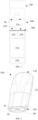
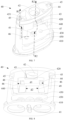
FIG. 1 is a schematic diagram of an electronic atomization apparatus according to an embodiment. -
FIG. 2 is a schematic diagram of an embodiment of an atomizer inFIG. 1 . -
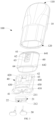
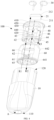
FIG. 3 is a schematic exploded view of the atomizer inFIG. 2 from a perspective. -
FIG. 4 is a schematic exploded view of the atomizer inFIG. 2 from another perspective. -
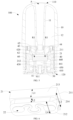
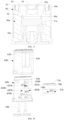
FIG. 5 is a schematic sectional view of the atomizer inFIG. 2 from a perspective. -
FIG. 6 is a schematic diagram of an atomization assembly inFIG. 5 from another perspective. -
FIG. 7 is a schematic diagram of a support inFIG. 3 from another perspective. -
FIG. 8 is a schematic diagram of a support inFIG. 7 from another perspective. -
FIG. 9 is a schematic diagram of a sealing element inFIG. 3 from another perspective. -
FIG. 10 is a schematic diagram of a sealing element inFIG. 9 from another perspective. -
FIG. 11 is a schematic sectional view of the sealing element inFIG. 9 from another perspective. -
FIG. 12 is a schematic diagram of a sealing element and a support inFIG. 3 before fitting. -
FIG. 13 is a schematic diagram of a fitted state of the sealing element and the support inFIG. 3 . -
FIG. 14 is a schematic diagram of another fitted state of the sealing element and the support inFIG. 13 . -
FIG. 15 is a schematic diagram of fitting the atomization assembly into the support. -
FIG. 16 is a schematic diagram of fitting the atomization assembly into a support according to another embodiment. -
FIG. 17 is a schematic diagram of the atomization assembly and the support inFIG. 16 after fitting. -
FIG. 18 is a schematic diagram of partial components in the atomizer according to another embodiment. -
FIG. 19 is a schematic diagram of fitting the atomization assembly into the support inFIG. 18 . -
FIG. 20 is a schematic diagram of moving the atomization assembly to a fastened position inside the support. -
FIG. 21 is a schematic diagram of partial components of the atomizer inFIG. 18 after fitting. - In the figures:
- 10. Main housing; 11. Aerosol output tube; 12. Liquid storage cavity; 100. Atomizer; 110. Proximal end; 120. Distal end;
- 21. Porous body; 21a. Porous body; 21b. Porous body; 22. Heating element; 200. Power supply mechanism; 210. Cell; 211. Surface; 212. Atomization surface; 213. Porous portion; 213b. Porous portion; 214. Porous portion; 214b. Porous portion; 220. Controller; 230. First electrical contact; 240. Charging interface; 250. Sensor; 260. Seal member; 270. Receiving cavity;
- 30. Second electrical contact; 30a. Second electrical contact;
- 40. Support; 40a. Support; 40b. Support; 41. Air inlet channel; 42. Plug-in hole; 43. Window; 44. Liquid channel; 45. Vent hole; 46. Groove; 47. Contact hole; 47a. Contact hole; 48. Opening; 48a. Opening; 48b. Opening; 49. Opening; 410. Connection end portion; 411. Tubular wall; 420. Separation wall; 420b. Separation wall; 430. Separation wall; 430b. Separation wall; 440. Cavity; 440a. Cavity; 440b. Cavity; 441. Atomization chamber; 450. Cavity; 451. Groove; 481b. Section; 482b. Section;
- 60. Sealing element; 60a. Sealing element; 60b. Sealing element; 61. Plug-in hole; 62. Sealing portion; 63. Opening; 65. Liquid guide hole; 66. Opening; 67. Columnar portion; 610. End wall; 620. Peripheral side wall; 622. Annular middle hole; 641. Sealing rib; 642. Sealing rib;
- 70b. Sealing element; 71b. Annular middle hole;
- A. Suction nozzle.
- For ease of understanding of this application, this application is described below in more detail with reference to drawings and specific implementations.
- This application provides an electronic atomization apparatus. Referring to
FIG. 1 , the electronic atomization apparatus includes: anatomizer 100, storing a liquid substrate and configured to atomize the liquid substrate to generate an aerosol; and apower supply mechanism 200, configured to supply power to theatomizer 100. - In an optional implementation, as shown in
FIG. 1 , thepower supply mechanism 200 includes: a receivingcavity 270 arranged on an end in a length direction and configured to receive and accommodate at least part of anatomizer 100; and a firstelectrical contact 230, at least partially exposed from a surface of the receivingcavity 270 and configured to form an electrical connection with theatomizer 100 to supply power to theatomizer 100 when at least part of theatomizer 100 is received and accommodated in thepower supply mechanism 200. - The
atomizer 100 is provided therein with an atomization assembly configured to atomize the liquid substrate to generate an aerosol. A secondelectrical contact 30 is arranged on an end portion of theatomizer 100 facing thepower supply mechanism 200 in the length direction, so that when at least part of theatomizer 100 is received in the receivingcavity 270, the secondelectrical contact 30 contacts and abuts against the firstelectrical contact 230 to form an electrical connection, thereby supplying power to the atomization assembly through the secondelectrical contact 30. - A
seal member 260 is arranged in thepower supply mechanism 200, and at least part of an internal space of thepower supply mechanism 200 is separated by theseal member 260 to form the receivingcavity 270. Theseal member 260 is constructed to extend in a direction perpendicular to the length direction of thepower supply mechanism 200, and is preferably made of a flexible material such as silica gel, so as to prevent the liquid substrate seeping from theatomizer 100 to the receivingcavity 270 from flowing to components such as acontroller 220 and asensor 250 inside thepower supply mechanism 200. - The
power supply mechanism 200 further includes: acell 210, facing away from the receivingcavity 270 in the length direction and configured to supply power; thecontroller 220, arranged between thecell 210 and the receivingcavity 270, where thecontroller 220 operably guides a current between thecell 210 and the firstelectrical contact 230. A charginginterface 240 is arranged on an other end of thepower supply mechanism 200 facing away from the receivingcavity 270, and is configured to charge thecell 210. - The
power supply mechanism 200 includes thesensor 250 configured to sense an inhalation airflow generated during inhalation of theatomizer 100 by a user, so that thecontroller 220 controls, based on a detection signal of thesensor 250, thecell 210 to output a current to theatomizer 100. -
FIG. 2 is a schematic structural diagram of an embodiment of theatomizer 100 inFIG. 1 . The atomizer includes:
amain housing 10. As shown inFIG. 2 andFIG. 3 , themain housing 10 is substantially in a shape of a flat cylinder or column. Themain housing 10 has aproximal end 110 and adistal end 120 opposite each other in a length direction. Based on a common use demand, theproximal end 110 is arranged as an aerosol inhalation end for a user, and a suction nozzle A is arranged on theproximal end 110 for inhalation by the user. Thedistal end 120 is an end to be integrated with thepower supply mechanism 200, and thedistal end 120 of themain housing 10 is an opening. The opening is configured for mounting necessary functional components to themain housing 10. The opening of thedistal end 120 of themain housing 10 is closed at thedistal end 120 by arigid support 40 after fitting. - Further, in a specific implementation shown in
FIG. 2 to FIG. 5 , the secondelectrical contact 30 runs through a surface of thedistal end 120 into theatomizer 100, and therefore is at least partially exposed from theatomizer 100, so that the second electrical contact can contact the firstelectrical contact 230 to form an electrical connection. In addition, anair inlet channel 41 is further provided on thesupport 40, which is configured for external air to enter theatomizer 100 during inhalation. - Further referring to
FIG. 3 to FIG. 5 , themain housing 10 is provided therein with aliquid storage cavity 12 configured to store a liquid substrate and an atomization assembly configured to absorb the liquid substrate from theliquid storage cavity 12 and heat and atomize the liquid substrate. The atomization assembly generally includes a capillary liquid guide element configured to absorb the liquid substrate and a heating element integrated on the liquid guide element. The heating element heats at least partial liquid substrate in the liquid guide element to generate an aerosol during power on. In an optional implementation, the liquid guide element includes flexible fibers such as cotton fibers, non-woven fabrics, and glass fiber ropes, or includes porous materials with a microporous structure, such as porous ceramic. The heating element may be integrated on the liquid guide element or wound on the liquid guide element through printing, deposition, sintering, physical fitting, or the like. - Further, in a preferred implementation shown in
FIG. 2 to FIG. 6 , the atomization assembly includes: aporous body 21, configured to absorb and transfer the liquid substrate; and aheating element 22, configured to heat and atomize the liquid substrate absorbed by theporous body 21. - Specifically, in the schematic structural sectional view shown in
FIG. 5 , themain housing 10 is provided therein with anaerosol output tube 11 arranged in an axial direction, in which an aerosol outlet channel is defined. In an implementation, at least part of theaerosol output tube 11 extends in theliquid storage cavity 12, and a space between an outer wall of theaerosol output tube 11 and an inner wall of themain housing 10 forms theliquid storage cavity 12. A first end of theaerosol output tube 11 facing theproximal end 110 is in communication with the suction nozzle A, and a second end thereof facing thedistal end 120 is in airflow connection with anatomization surface 212 of theporous body 21, so as to transfer the aerosol generated and released from the liquid substrate atomized by theheating element 22 to the suction nozzle A for inhalation. - An end portion of the
liquid storage cavity 12 defined between the outer wall of theaerosol output tube 11 and the inner wall of themain housing 10 close to theproximal end 110 is closed, and an end portion of theliquid storage cavity 12 facing thedistal end 120 is open, so that the liquid substrate can leave only through the open end. - Referring to a structure of the
porous body 21 shown inFIG. 3 to FIG. 6 , theporous body 21 is constructed in a structure substantially in a shape of a block in this embodiment, but the present invention is not limited thereto. In a preferred design of this embodiment, theporous body 21 is in the shape of a block, and is arranged substantially perpendicular to a longitudinal direction of theatomizer 100. Further, after fitting, theporous body 21 has asurface 211 and asurface 212 facing away from each other. During use, thesurface 211 is in fluid communication with theliquid storage cavity 12, and serves as a liquid absorbing surface configured to absorb the liquid substrate. Thesurface 212 faces away from theliquid storage cavity 12, and serves an atomization surface, for arranging theheating element 22 to atomize the liquid substrate to generate and release the aerosol. - In some specific implementations, a length dimension of the
porous body 21 is in a range of about 8 mm to 15 mm, a width dimension of theporous body 21 is in a range of about 4 mm to 8 mm, and a thickness dimension of theporous body 21 is in a range of about 3 mm to 6 mm. - Further referring to
FIG. 6 , theporous body 21 has aporous portion 213 and aporous portion 214 extending between thesurface 211 and thesurface 212. Theporous portion 213 defines thesurface 211, and theporous portion 214 defines thesurface 212. A thickness dimension L1 of theporous portion 213 is greater than a thickness dimension L2 of theporous portion 214. A width dimension L3 of theporous portion 213 is greater than a width dimension L4 of theporous portion 214. In a specific implementation, the thickness dimension L1 of theporous portion 213 is in a range of about 2 mm to 4 mm, and the thickness dimension L2 of theporous portion 214 is in a range of about 1 mm to 2 mm. The width dimension L3 of theporous portion 213 is in a range of about 4 mm to 8 mm, and the width dimension L4 of theporous portion 214 is in a range of about 3 mm to 6 mm. - After the fitting, a side wall of the
porous portion 213 in the width direction abuts against thesupport 40 for holding, and a side wall of theporous portion 214 and/or thesurface 212 in the width direction is not in contact with or is spaced apart from thesupport 40, which is advantageous to prevention of heat of thesurface 212 and/or theheating element 22 from being transferred to thesupport 40. - Certainly, the
heating element 22 is formed on thesurface 212. After the fitting, the secondelectrical contact 30 abuts against theheating element 22 to form an electrical connection, so as to supply power to theheating element 22. - Further referring to
FIG. 3 to FIG. 8 , thesupport 40 of theatomizer 100 at least partially accommodates and holds the atomization assembly. Specifically, thesupport 40 is made of a rigid material such as plastic, ceramic, or an organic polymer. Thesupport 40 is constructed to substantially extend in the longitudinal direction of theatomizer 100, and thesupport 40 has an upper end and a lower end facing away from each other in the longitudinal direction. After fitting, the upper end of thesupport 40 extends into themain housing 10, and the lower end of thesupport 40 is flush with thedistal end 120 of themain housing 10. After the fitting, at least a surface of the lower end of thesupport 40 is exposed from thedistal end 120 of themain housing 10. - The
support 40 has aconnection end portion 410 located at the lower end. Theconnection end portion 410 at least partially protrudes relative to other parts of thesupport 40, and is firmly connected to themain housing 10 by theconnection end portion 410 at thedistal end 120 of themain housing 10. Specifically, an engagement protrusion is arranged on theconnection end portion 410, and an engagement groove close to thedistal end 120 is provided on the inner wall of themain housing 10, which are mated and connected to each other after the fitting. Theconnection end portion 410 extends in a direction perpendicular to a longitudinal direction of thesupport 40. - The
support 40 further has aseparation wall 420 and aseparation wall 430 spaced apart in sequence in the longitudinal direction. Theseparation wall 420 and theseparation wall 430 both extend in the direction perpendicular to the longitudinal direction of thesupport 40. In some implementations, theseparation wall 420 and theseparation wall 430 are in a shape of a thin sheet or plate. - A
cavity 440 is defined between theseparation wall 420 and theseparation wall 430. After fitting, the atomization assembly is accommodated and held in thecavity 440. After the fitting, thesurface 212 of theporous body 21 used for atomization is adjacent to or faces theseparation wall 430, and thesurface 212 and theseparation wall 430 are spaced apart from each other. Further, after the fitting, a part of thecavity 440 located between thesurface 212 and theseparation wall 430 forms anatomization chamber 441. The aerosol atomized by thesurface 212 is released into theatomization chamber 441 and then outputted to theaerosol output tube 11. - A
contact hole 47 is provided on theseparation wall 430. After the fitting, the secondelectrical contact 30 extends through thecontact hole 47 and abuts against theheating element 22 to form an electrical connection. - The
contact hole 47 has an inner diameter in a range of about 4 mm to 6 mm, and the secondelectrical contact 30 has an outer diameter of about 3 mm. After the fitting, a gap or a spacing is maintained between the secondelectrical contact 30 and thecontact hole 47. - A
cavity 450 is defined between theseparation wall 430 and the connectingend portion 410. After the fitting, thecavity 450 is in communication with thecavity 440/theatomization chamber 441 through the gap or the spacing between the secondelectrical contact 30 and thecontact hole 47. In this way, during use, an aerosol condensate in thecavity 440/theatomization chamber 441 seeps into thecavity 450 through the gap or the spacing between the secondelectrical contact 30 and thecontact hole 47. Thecavity 450 serves as a condensate collection cavity to collect and hold the aerosol condensate generated in thecavity 440/theatomization chamber 441. - Two sides of the
cavity 450 in a thickness direction of thesupport 40 are open, and are closed after the fitting to prevent the collected condensate from seeping out. - Further referring further to
FIG. 5 to FIG. 8 , an upper end of thesupport 40 is provided with a plug-inhole 42, for a lower end of theaerosol output tube 11 to be fitted into the plug-inhole 42 during fitting. In addition, thesupport 40 has aliquid channel 44 extending from the upper end to theseparation wall 420. After the fitting, theliquid channel 44 is at least partially opposite and connected to thesurface 212 of theporous body 21 in the longitudinal direction of thesupport 40. In this way, the liquid substrate in theliquid storage cavity 12 can be transferred to thesurface 212 of theporous body 21 through theliquid channel 44, as shown by arrows R1 inFIG. 4 andFIG. 5 . - Referring to
FIG. 4 andFIG. 5 , at least one side of thesupport 40 in the thickness direction is provided with awindow 43. Thecavity 440/theatomization chamber 441 is in airflow communication with the plug-inhole 42 through thewindow 43. - The
air inlet channel 41 extends from theconnection end portion 410 to theseparation wall 430. External air enters theatomization chamber 441 through theair inlet channel 41. In addition, theair inlet channel 41 is at least partially defined by atubular wall 411 located in thecavity 450, as shown inFIG. 5 , so that theair inlet channel 41 and thecavity 450 are isolated from each other. - As shown in
FIG. 4 ,FIG. 5 , and an arrow R2 inFIG. 7 , on a complete inhalation airflow path, the external air enters theatomization chamber 441 through theair inlet channel 41, and carries the generated aerosol to span or bypass theporous body 21, and then enters theaerosol output tube 11 through thewindow 43 for output. - Further referring to
FIG. 8 , anopening 48 is formed on a side of thecavity 440 in the thickness direction of thesupport 40, and anopening 49 is formed on an other side thereof. In the implementation shown inFIG. 8 , a width dimension d1 of theopening 48 substantially matches the length of theporous body 21, a width dimension d2 of theopening 49 is less than the length of theporous body 21, and the width dimension d1 of theopening 48 is greater than the width dimension d2 of theopening 49. In this way, during fitting, the atomization assembly or theporous body 21 is allowed to be fitted into or removed from thecavity 440 in the thickness direction through theopening 48, and the atomization assembly or theporous body 21 is prevented from being fitted into or removed from thecavity 440 through theopening 49. The width dimension d1 of theopening 48 is in a range of about 8 mm to 15 mm. The width dimension d2 of theopening 49 is in a range of about 4 mm to 6 mm. - Further referring to
FIG. 3 to FIG. 5 andFIG. 9 to FIG. 11 , theatomizer 100 further includes a sealingelement 60 at least partially surrounding thesupport 40, to provide sealing in themain housing 10. The sealingelement 60 is made of a flexible material such as silicone, a thermoplastic elastomer (TPE), or another elastic polymer. The sealingelement 60 is a cylinder surrounding thesupport 40. An extension length of the sealingelement 60 is substantially the same as an extension length of thesupport 40. In this way, the sealingelement 60 can substantially completely surround thesupport 40 in length. - Referring to
FIG. 3 to FIG. 5 andFIG. 9 to FIG. 11 , the sealingelement 60 includes: - an
end wall 610, arranged perpendicular to a longitudinal direction of sealingelement 60, where after fitting, theend wall 610 abuts against the upper end of thesupport 40; - a
peripheral side wall 620, formed by extending from theend wall 610, where the peripheral side wall is substantially in an annular shape to surround thesupport 40. Theperipheral side wall 620 has a free end facing away from theend wall 610, and the free end is open. Thesupport 40 extends into theperipheral side wall 620 through the open free end. - The
end wall 610 of the sealingelement 60 is provided with: - a plug-in
hole 61, where during fitting, the plug-inhole 61 is opposite the plug-inhole 42 of thesupport 40. After the fitting, theaerosol output tube 11 successively passes through the plug-inhole 61 and the plug-inhole 42, and the sealingelement 60 at least partially provides sealing between theaerosol output tube 11 and the plug-inhole 42 of thesupport 40. - The
end wall 610 of the sealingelement 60 is further provided with:
aliquid guide hole 65, where during fitting, the liquid guide hole is opposite a port of theliquid channel 44 of thesupport 40 at an upper end, so that the liquid substrate in theliquid storage cavity 12 flows into the liquid channel through theliquid guide hole 65. - After the fitting, the
peripheral side wall 620 of the sealingelement 60 is located between themain housing 10 and thesupport 40, to provide sealing therebetween. Theperipheral side wall 620 of the sealingelement 60 is provided with: - a sealing
rib 641, close to theend wall 610 and surrounding theperipheral side wall 620, where after the fitting, the sealingrib 641 provides sealing at a position close to the open end of theliquid storage cavity 12, so that the liquid substrate in theliquid storage cavity 12 can substantially leave theliquid storage cavity 12 only through theliquid guide hole 65; and - a sealing
rib 642, close to the free end of theperipheral side wall 620 facing away from theend wall 610, and surrounding theperipheral side wall 620, where after the fitting, the sealingrib 642 is supported by the connectingend portion 410 of thesupport 40, to provide sealing near thedistal end 12 of themain housing 10. - The
peripheral side wall 620 of the sealingelement 60 is provided with: - an
opening 66, located on one side in the thickness direction, where after the fitting, theopening 66 is opposite theopening 48 of thesupport 40, a width dimension d3 of theopening 66 is substantially equal to the width dimension d1 of theopening 48 of thesupport 40, theporous body 21 or the atomization assembly can be received into thesupport 40 surrounded by theperipheral side wall 620 through theopening 66; and - an
opening 63, located on an other side in the thickness direction, where after the fitting, theopening 66 is opposite theopening 49 of thesupport 40, a width dimension d4 of thisopening 63 is less than the width dimension d3 of theopening 66, and the width dimension d4 of theopening 63 is substantially equal to the width dimension d2 of theopening 49 of thesupport 40. - In a specific implementation, an extension dimension of the
opening 63 and/or theopening 66 in the longitudinal direction of the sealingelement 60 covers thewindow 43 of thesupport 40, or theopening 63 and/or theopening 66 is at least partially opposite or at least partially coincides with thewindow 43 ofsupport 40 in the thickness direction ofsupport 40, which is advantageous to prevent impact on the output of the aerosol through thewindow 43 as a result of shielding or blocking of thewindow 43. - Further referring to
FIG. 5 ,FIG. 10 , andFIG. 11 , the sealingelement 60 is further provided with:
a sealingportion 62, where the sealingportion 62 is constructed in an annular shape, and the sealingportion 62 is in a thin shape with a smaller dimension in an axial direction. Specifically, a wall thickness dimension d5 of the sealingportion 62 between an inner surface and an outer surface is in a range of about 2 mm to 4 mm. A height dimension d6 of the sealingportion 62 in the axial direction is in a range of about 3 mm to 5 mm. - An outer contour of the sealing
portion 62 is in a rectangular shape the same as a shape of thesurface 211 of theporous body 21. Specifically, a length of the outer contour of the sealingportion 62 is substantially equal to a length of thesurface 211 of theporous body 21, and a width of the outer contour of the sealingportion 62 is substantially equal to a width of thesurface 211 of theporous body 21. - As shown in
FIG. 5 , after fitting, the sealingportion 62 is located between thesurface 211 of theporous body 21 and theseparation wall 420 to provide sealing therebetween. Specifically, the sealingportion 62 with an annularmiddle hole 622 faces the port of theporous body 21/the atomization assembly while surrounding theliquid channel 44, so that the liquid substrate flowing out through theliquid channel 44 can only flow toward thesurface 211 of theporous body 21, and
after the fitting, the sealingportion 62 is arranged substantially parallel to theseparation wall 420 and thesurface 211 of theporous body 21. - Further referring to
FIG. 10 andFIG. 11 , the sealingportion 62 is connected to an inner surface of theperipheral side wall 620 through abendable connection arm 621. The sealingportion 62 is connected to an inner surface on a side of theopening 66 close to theperipheral side wall 620 only through theconnection arm 621, and is not connected to an inner surface of theopening 63 close to theperipheral side wall 620. In this way, the sealingportion 62 may be flipped or changed around thebendable connection arm 621, and can extend from theopening 66 to outside of the sealingelement 60. -
FIG. 12 to FIG. 15 are schematic diagrams of a fitting process of the sealingelement 60, thesupport 40, and the atomization assembly according to an embodiment. Specifically, the process includes the following:
Referring toFIG. 12 , the sealingportion 62 of the sealingelement 60 is pulled or bent to extend to the outside of the sealingelement 60 through theopening 66. Then thesupport 40 is fitted into the sealingelement 60 from the free end of theperipheral side wall 620 of the sealingelement 60 along an arrow P1 inFIG. 12 , until the upper end of thesupport 40 abuts against theend wall 610 of the sealingelement 60. - The sealing
portion 62 of the sealingelement 60 is bent along an arrow P2 shown inFIG. 13 , to successively pass through theopening 66 and theopening 48 of thesupport 40, and then extend into thecavity 440 of thesupport 40, and abut against theseparation wall 420 of thesupport 40, to form a fitted state of the sealingelement 60 and thesupport 40 inFIG. 14 . - The atomization assembly/the
porous body 21 is further fitted into thecavity 440 of thesupport 40 successively through theopening 66 and theopening 48 along an arrow R3 shown inFIG. 15 , and is caused to abut against the sealingportion 62. Finally, the secondelectrical contact 30 is inserted from the lower end of thesupport 40 and is caused to abut against the atomization assembly. - In this implementation, the
connection arm 621 and the sealingportion 62 made of flexible materials may be selectively pulled out from the sealingelement 60 through theopening 66 or inserted into the sealingelement 60 from the outside of the sealing element through operations such as pulling or bending. - In the design of the
above sealing element 60, the sealingportion 62 is moved out or in, to avoid or eliminate interference on the fitting of thesupport 40 into the sealingelement 60, and facilitate placement of the sealingportion 62 between the atomization assembly and theseparation wall 420 of thesupport 40 after thesupport 40 is fitted into the sealingelement 60. - Alternatively, in some other variable implementations, the sealing
portion 62 surrounds the atomization assembly/theporous body 21 in a circumferential direction of the atomization assembly/theporous body 21. After the fitting, the sealing portion is arranged between the atomization assembly/theporous body 21 and thesupport 40 in a cross-sectional direction of thesupport 40, to provide sealing. - In an implementation, the width dimension of the
opening 63 of the sealingelement 60 is less than that of theopening 66. In this way, the atomization assembly/theporous body 21 is prevented from being received into or removed from the sealingelement 60 and/or thesupport 40 through theopening 63. - In an implementation, an extension length of the
opening 63 of the sealingelement 60 is the same as an extension length of theopening 66. - Further, in some implementations, referring to
FIG. 4 ,FIG. 5 ,FIG. 7 ,FIG. 9 , andFIG. 11 , thesupport 40 is further provided with avent hole 45 close to the upper end. A lower end of thevent hole 45 is in airflow communication with theatomization chamber 441 through agroove 46 on an outer surface of thesupport 40. An upper end of thevent hole 45 faces theliquid storage cavity 12. Correspondingly, the sealingelement 60 further has acolumnar portion 67 extending from theend wall 610. As shown in the figure, thecolumnar portion 67 is in a shape of a column. After the fitting, thecolumnar portion 67 extends from the upper end into thevent hole 45. - In an implementation, the
vent hole 45 has an extension length in a range of about 3 mm to 10 mm, and thevent hole 45 has an inner diameter in a range of 3 mm to 6 mm. Thecolumnar portion 67 has a length in a range of about 3 mm to 10 mm and a length by which a second section 820 extends in the longitudinal direction is an outer diameter in a range of about 3 mm to 6 mm. An inner surface of thevent hole 45 is provided with agroove 451 extending in an axial direction, to maintain a gap or an air gap between the column portion and the vent hole after the fitting. In this way, air in theatomization chamber 441 can successively pass through thegroove 46 and the gap or the air gap between thevent hole 45 and thecolumnar portion 67 along the arrow R3 inFIG. 4 orFIG. 7 and enter theliquid storage cavity 12, so as to supply air into theliquid storage cavity 12 to relieve negative pressure in theliquid storage cavity 12. - In an implementation, the
groove 451 has a width of about 0.5 mm and a depth of about 0.5 mm, a cross-sectional area of an air channel defined by thegroove 451 is designed to be less than 1 mm2 to prevent the liquid substrate from leaking from the air channel. - A plurality of
grooves 451 may be arranged at an interval in a circumferential direction. Alternatively, in some other variable implementations, thegroove 451 may be provided on an outer surface of thecolumnar portion 67. - Further referring to
FIG. 5 ,FIG. 9, and FIG. 10 , thevent hole 45 and thecolumnar portion 67 of the sealingelement 60 are both staggered from theliquid channel 44. Thecolumnar portion 67 extends from theend wall 610 of the sealingelement 60. Specifically, awall 671 of theliquid guide hole 65 is defined on theend wall 610 of the sealingelement 60. Thecolumnar portion 67 extends from thewall 671. The sealingelement 60 further has anavoidance hole 672 closer to an end portion in the width direction than theliquid guide hole 65, so that air entering the gap or the air gap between thevent hole 45 and thecolumnar portion 67 enters theliquid storage cavity 12 through theavoidance hole 672. In an implementation, theavoidance hole 672 is in a shape of a curved arc. In addition, theavoidance hole 672 is isolated from theliquid guide hole 65. A cross-sectional area of theavoidance hole 672 is less than an area of theliquid guide hole 65. - Further,
FIG. 16 andFIG. 17 are schematic exploded views of asupport 40a, an atomization assembly, and a secondelectrical contact 30a before fitting according to another embodiment. In an implementation, thesupport 40a has anopening 48a located on a side in a width direction. During fitting, the atomization assembly/aporous body 21a is fitted into thecavity 440a in the width direction of thesupport 40a through theopening 48a. Then the secondelectrical contact 30a is caused to run through acontact hole 47a and abut against the atomization assembly/a heating element, i.e., a fitted state shown inFIG. 17 is formed. - As shown in
FIG. 17 , theopening 48a is blocked or covered by a sealing element 60a after the fitting. - Further,
FIG. 18 to FIG. 21 are schematic diagrams of fitting of partial components of theatomizer 100 according to another variable embodiment. In this implementation, theatomizer 100 includes:
asupport 40b, including aseparation wall 420b and aseparation wall 430b; and acavity 440b, defined between theseparation wall 420b and theseparation wall 430b, where thecavity 440 includes aportion 441b close to theseparation wall 420b and aportion 442b close to theseparation wall 430b. A width and/or a volume of theportion 442b is greater than a width and/or a volume of theportion 441b. - Correspondingly, the
support 40b has anopening 48b located on a side in a thickness direction. Theopening 48b includes asection 481b opposite theportion 441b and asection 482b opposite theportion 442b. A width of thesection 482b is greater than that of thesection 481b. Specifically, the width d11 of thesection 481b is in a range of about 4 mm to 6 mm, the width d12 of thesection 482b is in a range of about 8 mm to 15 mm, and a length of aporous body 21b is in a range of about 8 mm to 15 mm. The design of the width dimensions of thesection 481b and thesection 482b of theopening 48b enables thesection 482b to allow the atomization assembly/theporous body 21b to be received in theportion 442b in a thickness direction and prevent the atomization assembly/theporous body 21b from being removed from thesection 481b. - Referring to
FIG. 19 and FIG. 20 , a fitting process includes the following steps: - causing a
sealing element 70b with an annularmiddle hole 71b to abut against a surface 221b of theporous body 21b of the atomization assembly, as shown by an arrow P10 in the figure; - fitting the sealing
element 70b and theporous body 21b into theportion 442b of thecavity 440 in the thickness direction through thesection 482b of theopening 48b along an arrow P20 in the figure; - pushing or moving the sealing
element 70b and theporous body 21b located in theportion 442b into theportion 441b of the cavity in a longitudinal direction of thesupport 40b along the arrow P30 in the figure, and causing the sealing element and the porous body to abut against theseparation wall 420b; - inserting the second
electrical contact 30b into thesupport 40b from a lower end, and causing the second electrical contact to abut against the heating element located on the surface of theporous body 21; and - sleeving a
sealing element 60b outside thesupport 40b. - In this implementation, after the fitting, the sealing
element 60b is configured to provide sealing between thesupport 40b and themain housing 10 support, and the sealingelement 70b is configured to provide sealing between thesupport 40b and the atomization assembly/theporous body 21b. - In this implementation, during the fitting, the atomization assembly/the
porous body 21b is moved to theportion 442b of thecavity 440b in the thickness direction of thesupport 40b through thesection 482b of theopening 48b, and is then moved to theportion 441b of thecavity 440b in the longitudinal direction ofsupport 40b. - After the fitting, referring to
FIG. 21 , aporous portion 214b of theporous body 21b with a smaller cross-sectional area is located in theportion 442b of thecavity 440b, and a porous portion 213b of theporous body 21b with a larger cross-sectional area is located in theportion 441b of thecavity 440b. After the fitting, the porous portion 213b substantially abuts against an inner surface of theportion 441b of thecavity 440b, and theporous portion 214b is spaced apart from and therefore does not abut against or contacts theportion 442b of thecavity 440b, which is advantageous to prevention of transfer of heat generated by the heating element to thesupport 40b. - In this implementation, during the fitting of the atomization assembly/the
porous body 21b, thesection 482b of theopening 48b is substantially staggered by a distance from theportion 441b of thecavity 440b mainly configured for accommodation and holding, which is advantageous to prevention of the atomization assembly/theporous body 21b held in theportion 441b of thecavity 440b from loosening or falling out from thesection 481b of theopening 48b. - In this implementation, an extension length of the
section 481b covers thewindow 43b of thesupport 40b, so that an aerosol in an atomization chamber enters theaerosol output tube 11 through thewindow 43b. - In this implementation, the sealing
element 70b configured to provide sealing between the atomization assembly/theporous body 21b and thesupport 40b is separated from the sealingelement 60b. Correspondingly, during the fitting, the sealingelement 70b and the atomization assembly/theporous body 21b may be fitted to thesupport 40b earlier than the sealingelement 60b. In this case,openings 63b with smaller widths are provided on two sides of the sealingelement 60b in the thickness direction. To be specific, the width of theopening 63b is less than the width d12 of thesection 482b of theopening 48b, and the width of theopening 63b is less than the length of the atomization assembly/theporous body 21b. In this way, theopening 63b can prevent the atomization assembly/theporous body 21b from being fitted into or removed from interior of the sealingelement 60b through theopenings 63b. - In addition, after the fitting, the
section 482b of theopening 48b of thesupport 40b is at least partially blocked or covered by the sealingelement 60b. Therefore, a part of the atomization assembly/theporous body 21b exposed from thesection 482b of theopening 48b is finally blocked or covered by the sealingelement 60b. - It should be noted that, the specification and the drawings of this application provide the preferred embodiments of this application, but this application is not limited to the embodiments described in this specification. Further, a person of ordinary skill in the art may make improvements or modifications according to the foregoing descriptions, and all of the improvements and modifications shall fall within the protection scope of the appended claims of this application.
Claims (28)
- An atomizer, comprising a housing, wherein the housing is provided therein with:a liquid storage cavity, configured to store a liquid substrate;an atomization assembly, configured to atomize the liquid substrate to generate an aerosol;a support, having a first cavity, wherein the atomization assembly is accommodated in the first cavity; anda flexible sealing element, comprising a peripheral side wall, wherein:the peripheral side wall is arranged to be located between the support and the housing and at least partially surround the support, to provide sealing between the support and the housing;the sealing element further comprises a sealing portion extending into the first cavity; andthe sealing portion is arranged to be at least partially located between an inner surface of the first cavity and the atomization assembly, to provide sealing between the inner surface of the first cavity and the atomization assembly.
- The atomizer according to claim 1, wherein:the support further defines a liquid channel, and the atomization assembly is in fluid communication with the liquid storage cavity through the liquid channel, to receive the liquid substrate in the liquid storage cavity; andthe liquid channel has a liquid outlet port located on the inner surface of the first cavity, and the sealing portion is arranged to surround the liquid outlet port.
- The atomizer according to claim 1 or 2, wherein the sealing portion is constructed in an annular shape.
- The atomizer according to claim 1 or 2, wherein the atomization assembly comprises:a porous body, having a first surface and a second surface, wherein the first surface is configured to be in fluid communication with the liquid storage cavity to receive the liquid substrate; anda heating element, integrated on the second surface to heat the liquid substrate to generate an aerosol,wherein the sealing portion is arranged to be located between the first surface and the inner surface of the first cavity.
- The atomizer according to claim 4, wherein the sealing portion has no portion surrounding the porous body in a circumferential direction of the porous body.
- The atomizer according to claim 4, wherein:the porous body comprises a first porous portion and a second porous portion arranged in sequence in a longitudinal direction of the support, and a cross-sectional area of the second porous portion is less than a cross-sectional area of the first porous portion; andthe first surface is formed on the first porous portion, and the second surface is formed on the second porous portion.
- The atomizer according to claim 6, wherein the first porous portion abuts against the inner surface of the first cavity, and the second porous portion is substantially not in contact with the inner surface of the first cavity.
- The atomizer according to claim 6, wherein:the first cavity comprises a first portion and a second portion arranged in sequence in the longitudinal direction of the support, and a cross-sectional area of the first portion is less than that of the second portion;the first porous portion is accommodated in the first portion; andthe second porous portion is accommodated in the second portion.
- The atomizer according to claim 1 or 2, wherein:the support has a transverse direction perpendicular to a longitudinal direction;the support is provided with a first opening located on one side of the transverse direction; andthe atomization assembly is configured to be received in the first cavity or removed from the first cavity through the first opening.
- The atomizer according to claim 9, wherein a width of the first opening is greater than a length of the atomization assembly.
- The atomizer according to claim 9, wherein:the support is provided with a second opening located on an other side of the transverse direction;the atomization assembly is partially exposed from the second opening; anda width of the second opening is less than the width of the first opening.
- The atomizer according to claim 9, wherein the sealing portion of the sealing element extends into the first cavity through the first opening.
- The atomizer according to claim 9, wherein:the sealing element further comprises at least one connection arm located between the peripheral side wall and the sealing portion;the sealing portion is connected to the peripheral side wall through the at least one connection arm; andthe at least one connection arm is bendable.
- The atomizer according to claim 13, wherein the at least one connection arm is arranged near the first opening.
- The atomizer according to claim 1 or 2, wherein:the first cavity comprises a first portion and a second portion arranged in sequence in a longitudinal direction of the support, a cross-sectional area of the first portion is less than that of the second portion, and the atomization assembly is at least partially accommodated and held in the first portion;the support has a transverse direction perpendicular to the longitudinal direction, the support is provided with a first opening located on one side of the transverse direction, the first opening comprises a first section, a width of the first section is greater than or equal to a length of the atomization assembly, and the atomization assembly is configured to be received in the first cavity in the transverse direction through the first section; andthe first section is staggered with respect to the first portion in the longitudinal direction of the support.
- The atomizer according to claim 15, wherein:the first opening further comprises a second section facing the first portion in the longitudinal direction of the support; andthe width of the second section is less than the length of the atomization assembly to prevent the atomization assembly from entering the first portion in the transverse direction through the second section.
- The atomizer according to claim 1 or 2, wherein:the first cavity comprises a first portion and a second portion arranged in sequence in a longitudinal direction of the support, and a cross-sectional area of the first portion is less than that of the second portion; andthe support has a transverse direction perpendicular to the longitudinal direction, the support has a first opening provided in the transverse direction, and the atomization assembly is configured to be received in the second portion in the transverse direction through the first opening and at least partially moved from the second portion into the first portion for stop.
- The atomizer according to claim 1 or 2, further comprising:
an air channel, configured to provide a flowing path for air to enter the liquid storage cavity from the first cavity. - The atomizer according to claim 18, wherein:the support is provided with a vent hole; andthe sealing element further comprises a columnar portion at least partially extending in the vent hole, and the air channel is defined between an outer surface of the columnar portion and an inner surface of the vent hole.
- The atomizer according to claim 19, wherein:the sealing element further comprises an end wall, a liquid guide hole is provided on the end wall, and the end wall is constructed to seal the liquid storage cavity, so that the liquid substrate substantially leaves only through the liquid guide hole; andthe columnar portion extends from the end wall into the vent hole.
- The atomizer according to claim 20, wherein an avoidance hole adjacent to the columnar portion is further provided on the end wall, so that air in the air channel enters the liquid storage cavity through the avoidance hole.
- The atomizer according to claim 21, wherein the avoidance hole is in a shape of a curved arc.
- The atomizer according to claim 21, wherein an area of the avoidance hole is less than an area of the liquid guide hole.
- The atomizer according to claim 9, wherein the peripheral side wall is provided with a third opening facing the first opening, and a width of the third opening is greater than or equal to a width of the first opening.
- The atomizer according to claim 1 or 2, wherein:the support further comprises a second cavity, farther away from the liquid storage cavity than the first cavity; andthe second cavity is in fluid communication with the first cavity to receive and hold an aerosol condensate in the first cavity.
- An electronic atomization apparatus, comprising an atomizer configured to atomize a liquid substrate to generate an aerosol and a power supply mechanism configured to supply power to the atomizer, wherein the atomizer comprises the atomizer according to any of claims 1 to 25.
- A sealing element for an electronic atomization apparatus, wherein:the sealing element is flexible, and the sealing element has a longitudinal direction and a transverse direction perpendicular to the longitudinal direction; andthe sealing element comprises:a peripheral side wall, constructed to extend in the longitudinal direction, wherein the peripheral side wall has a third opening provided in the transverse direction; andthe sealing element further comprises a sealing portion connected to the peripheral side wall, and the sealing portion is constructed to selectively extend into or be removed from a space defined by the peripheral side wall through the third opening.
- The sealing element for an electronic atomization apparatus according to claim 27, wherein the peripheral side wall is further provided with a fourth opening facing the third opening in the transverse direction, and a width of the third opening is greater than a width of the fourth opening.
Applications Claiming Priority (2)
| Application Number | Priority Date | Filing Date | Title |
|---|---|---|---|
| CN202210132264.7A CN116616499A (en) | 2022-02-14 | 2022-02-14 | Atomizer, electronic atomization device and sealing element for electronic atomization device |
| PCT/CN2023/075236 WO2023151626A1 (en) | 2022-02-14 | 2023-02-09 | Atomizer, electronic atomization apparatus, and sealing element for electronic atomization apparatus |
Publications (2)
| Publication Number | Publication Date |
|---|---|
| EP4458184A1 true EP4458184A1 (en) | 2024-11-06 |
| EP4458184A4 EP4458184A4 (en) | 2025-05-14 |
Family
ID=87563683
Family Applications (1)
| Application Number | Title | Priority Date | Filing Date |
|---|---|---|---|
| EP23752406.1A Pending EP4458184A4 (en) | 2022-02-14 | 2023-02-09 | Atomizer, electronic atomizing device and sealing element for electronic atomizing device |
Country Status (4)
| Country | Link |
|---|---|
| US (1) | US20250134174A1 (en) |
| EP (1) | EP4458184A4 (en) |
| CN (1) | CN116616499A (en) |
| WO (1) | WO2023151626A1 (en) |
Families Citing this family (1)
| Publication number | Priority date | Publication date | Assignee | Title |
|---|---|---|---|---|
| CN117338055A (en) * | 2023-09-22 | 2024-01-05 | 深圳市华诚达精密工业有限公司 | Electronic aerosol generating device and its atomizer |
Family Cites Families (24)
| Publication number | Priority date | Publication date | Assignee | Title |
|---|---|---|---|---|
| WO2015006931A1 (en) * | 2013-07-16 | 2015-01-22 | 吉瑞高新科技股份有限公司 | Electronic cigarette |
| CN106793830B (en) * | 2014-09-02 | 2019-06-28 | 惠州市吉瑞科技有限公司 | Atomizing components and electronic cigarettes |
| CN108142999B (en) * | 2016-12-02 | 2021-02-05 | 卓尔悦欧洲控股有限公司 | Liquid storage assembly and atomizer and electronic cigarette thereof |
| CN110051044B (en) * | 2019-04-17 | 2024-12-03 | 深圳市艾维普思科技有限公司 | Atomization device of electronic cigarette and electronic cigarette |
| CN211482971U (en) * | 2019-11-26 | 2020-09-15 | 深圳市合元科技有限公司 | Atomizers and Electronic Cigarettes |
| CN111557472A (en) * | 2020-01-16 | 2020-08-21 | 深圳雾芯科技有限公司 | an atomizing device |
| CN113796578B (en) * | 2020-06-16 | 2025-12-02 | 深圳市合元科技有限公司 | Electronic cigarette atomizers and electronic cigarettes |
| CN212590252U (en) * | 2020-06-16 | 2021-02-26 | 深圳市合元科技有限公司 | Electronic cigarette atomizer and electronic cigarette |
| CN212852491U (en) * | 2020-06-16 | 2021-04-02 | 深圳市合元科技有限公司 | Electronic Cigarettes and Electronic Cigarettes |
| CN113796579A (en) * | 2020-06-16 | 2021-12-17 | 深圳市合元科技有限公司 | Electronic cigarette atomizer and electronic cigarette |
| CN215347025U (en) * | 2021-03-31 | 2021-12-31 | 深圳市合元科技有限公司 | Atomizer, electronic atomization device and sealing element for atomizer |
| CN213604379U (en) * | 2020-09-15 | 2021-07-06 | 深圳市合元科技有限公司 | Electronic Cigarettes and Electronic Cigarettes |
| CN213587425U (en) * | 2020-09-15 | 2021-07-02 | 深圳市合元科技有限公司 | Electronic Cigarettes and Electronic Cigarettes |
| CN213819836U (en) * | 2020-10-21 | 2021-07-30 | 深圳市合元科技有限公司 | Atomizers and Electronic Atomizers |
| CN214431782U (en) * | 2020-11-25 | 2021-10-22 | 深圳市合元科技有限公司 | Atomizer and electronic atomization device |
| CN215347020U (en) * | 2021-03-11 | 2021-12-31 | 深圳市合元科技有限公司 | Atomizer and electronic atomization device |
| CN215684777U (en) * | 2021-03-15 | 2022-02-01 | 深圳市合元科技有限公司 | Atomizer and electronic atomization device |
| CN215347029U (en) * | 2021-03-24 | 2021-12-31 | 深圳市合元科技有限公司 | Nebulizer, electronic nebulizer and sealing element for nebulizer |
| CN215347044U (en) * | 2021-05-07 | 2021-12-31 | 深圳市合元科技有限公司 | Atomizer and electronic atomization device |
| CN215347030U (en) * | 2021-05-25 | 2021-12-31 | 深圳市合元科技有限公司 | Atomizers and Electronic Atomizers |
| CN215381468U (en) * | 2021-06-25 | 2022-01-04 | 比亚迪精密制造有限公司 | Electronic cigarette atomizing device and electronic cigarette |
| CN215684856U (en) * | 2021-07-21 | 2022-02-01 | 深圳市合元科技有限公司 | Atomizer, electronic atomization device and sealing element for atomizer |
| CN215684857U (en) * | 2021-08-03 | 2022-02-01 | 深圳市合元科技有限公司 | Atomizer and electronic atomization device |
| CN217826742U (en) * | 2022-02-14 | 2022-11-18 | 深圳市合元科技有限公司 | Atomizer, electronic atomization device and support for atomizer |
-
2022
- 2022-02-14 CN CN202210132264.7A patent/CN116616499A/en active Pending
-
2023
- 2023-02-09 WO PCT/CN2023/075236 patent/WO2023151626A1/en not_active Ceased
- 2023-02-09 EP EP23752406.1A patent/EP4458184A4/en active Pending
- 2023-02-09 US US18/837,943 patent/US20250134174A1/en active Pending
Also Published As
| Publication number | Publication date |
|---|---|
| EP4458184A4 (en) | 2025-05-14 |
| US20250134174A1 (en) | 2025-05-01 |
| WO2023151626A1 (en) | 2023-08-17 |
| CN116616499A (en) | 2023-08-22 |
Similar Documents
| Publication | Publication Date | Title |
|---|---|---|
| US20250098773A1 (en) | Vaporizer and electronic vaporization device | |
| CN218737203U (en) | Atomizer and electronic atomization device | |
| EP4458183A1 (en) | Electronic atomization device and support for electronic atomization device | |
| CN217826742U (en) | Atomizer, electronic atomization device and support for atomizer | |
| US20250134174A1 (en) | Atomizer, electronic atomization apparatus, and sealing element for electronic atomization apparatus | |
| CN115670013A (en) | An atomizer and its electronic atomization device | |
| CN114847527A (en) | Atomizer and electronic atomization device | |
| CN215684857U (en) | Atomizer and electronic atomization device | |
| CN220712894U (en) | Atomizer and electronic atomization device | |
| US20250248452A1 (en) | Electronic atomization device | |
| EP4335313A1 (en) | Atomizer and electronic atomization device | |
| EP4285747A1 (en) | Atomizer and electronic atomization device | |
| CN217429249U (en) | Atomizer and electronic atomization device | |
| CN215347034U (en) | Atomizer and electronic atomization device | |
| EP4728902A1 (en) | Atomizer and electronic atomization device | |
| EP4487703A1 (en) | Atomizer and electronic atomization device | |
| CN216701695U (en) | Atomizer and electronic atomization device | |
| CN218737218U (en) | Atomizer and electronic atomization device thereof | |
| EP4248779A1 (en) | Vaporizer and electronic vaporization device | |
| CN115474715A (en) | Atomizers and Electronic Atomization Devices | |
| CN114847520A (en) | Atomizer and electronic atomization device | |
| CN219982149U (en) | Atomizer and electronic atomization device | |
| EP4602954A1 (en) | Atomizer and electronic atomization device | |
| CN220458603U (en) | Atomizer, electronic atomization device and support for atomizer | |
| EP4646951A1 (en) | Atomizer, electronic atomization apparatus, and atomization assembly |
Legal Events
| Date | Code | Title | Description |
|---|---|---|---|
| STAA | Information on the status of an ep patent application or granted ep patent |
Free format text: STATUS: THE INTERNATIONAL PUBLICATION HAS BEEN MADE |
|
| PUAI | Public reference made under article 153(3) epc to a published international application that has entered the european phase |
Free format text: ORIGINAL CODE: 0009012 |
|
| STAA | Information on the status of an ep patent application or granted ep patent |
Free format text: STATUS: REQUEST FOR EXAMINATION WAS MADE |
|
| 17P | Request for examination filed |
Effective date: 20240802 |
|
| AK | Designated contracting states |
Kind code of ref document: A1 Designated state(s): AL AT BE BG CH CY CZ DE DK EE ES FI FR GB GR HR HU IE IS IT LI LT LU LV MC ME MK MT NL NO PL PT RO RS SE SI SK SM TR |
|
| A4 | Supplementary search report drawn up and despatched |
Effective date: 20250411 |
|
| RIC1 | Information provided on ipc code assigned before grant |
Ipc: A24F 40/485 20200101ALI20250407BHEP Ipc: A24F 40/10 20200101ALI20250407BHEP Ipc: A24F 40/40 20200101AFI20250407BHEP |
|
| DAV | Request for validation of the european patent (deleted) | ||
| DAX | Request for extension of the european patent (deleted) |