EP4458129A1 - Agricultural harvester - Google Patents
Agricultural harvester Download PDFInfo
- Publication number
- EP4458129A1 EP4458129A1 EP24165344.3A EP24165344A EP4458129A1 EP 4458129 A1 EP4458129 A1 EP 4458129A1 EP 24165344 A EP24165344 A EP 24165344A EP 4458129 A1 EP4458129 A1 EP 4458129A1
- Authority
- EP
- European Patent Office
- Prior art keywords
- crop
- sensor
- belt
- actuator
- forage harvester
- Prior art date
- Legal status (The legal status is an assumption and is not a legal conclusion. Google has not performed a legal analysis and makes no representation as to the accuracy of the status listed.)
- Pending
Links
Images


Classifications
-
- A—HUMAN NECESSITIES
- A01—AGRICULTURE; FORESTRY; ANIMAL HUSBANDRY; HUNTING; TRAPPING; FISHING
- A01D—HARVESTING; MOWING
- A01D43/00—Mowers combined with apparatus performing additional operations while mowing
- A01D43/08—Mowers combined with apparatus performing additional operations while mowing with means for cutting up the mown crop, e.g. forage harvesters
- A01D43/085—Control or measuring arrangements specially adapted therefor
-
- A—HUMAN NECESSITIES
- A01—AGRICULTURE; FORESTRY; ANIMAL HUSBANDRY; HUNTING; TRAPPING; FISHING
- A01D—HARVESTING; MOWING
- A01D43/00—Mowers combined with apparatus performing additional operations while mowing
- A01D43/08—Mowers combined with apparatus performing additional operations while mowing with means for cutting up the mown crop, e.g. forage harvesters
- A01D43/081—Mowers combined with apparatus performing additional operations while mowing with means for cutting up the mown crop, e.g. forage harvesters specially adapted for ensilage of maize
-
- A—HUMAN NECESSITIES
- A01—AGRICULTURE; FORESTRY; ANIMAL HUSBANDRY; HUNTING; TRAPPING; FISHING
- A01D—HARVESTING; MOWING
- A01D43/00—Mowers combined with apparatus performing additional operations while mowing
- A01D43/10—Mowers combined with apparatus performing additional operations while mowing with means for crushing or bruising the mown crop
- A01D43/102—Bruising control devices
-
- A—HUMAN NECESSITIES
- A01—AGRICULTURE; FORESTRY; ANIMAL HUSBANDRY; HUNTING; TRAPPING; FISHING
- A01D—HARVESTING; MOWING
- A01D43/00—Mowers combined with apparatus performing additional operations while mowing
- A01D43/10—Mowers combined with apparatus performing additional operations while mowing with means for crushing or bruising the mown crop
- A01D43/105—Driving mechanisms
Definitions
- the present invention relates to an agricultural harvester, and, in particular, to a forage harvester and improvements relating to the control of the drive system for a grain processor of a forage harvester.
- Such harvesters may comprise a header apparatus for harvesting a crop, a chopping apparatus for chopping the harvested crop and grain processor for processing of the chopped crop.
- a control device may be provided for adjusting the degree of processing of the grain processor.
- the processed crop may be used as fodder for livestock.
- the corn kernels are not digestible in an intact condition. Accordingly, the chopped crop is passed in the grain processor through two or more cracker rollers between which the kernels are opened up or crushed in order to expose the inside of the kernels.
- the degree of processing of the chopped crop which is related to the belt tension in the drive of the grain processor, determines on the one hand the proportion of broken down or crushed kernels and on the other hand also the energy requirement for operation of the grain processor.
- the aim is to find a favourable operating point for the grain processor between achieving breaking down of a sufficiently high proportion of the kernels passing through the grain processor and minimising the energy requirement for operation of the grain processor.
- a forage harvester comprises a grain processor for processing of a chopped crop, the grain processor being driven by a belt drive in which an endless belt has a belt tension, an actuator for adjusting the belt tension in the belt drive and a control device for adjusting the actuator, the control device being configured to control the actuator based on input signals supplied to the control device with regard to a property of the crop and a stored relationship between the signal and an associated setting value of the actuator in terms of adapting the belt tension in the belt drive to the property of the crop, the control device being configured to receive the input signals from either i) a sensor that interacts with the crop upstream of the grain processor and/or ii) taken location-specific from a stored map and the actuator commanded to adjust the belt tension in the belt drive based on the input signals related to the crop being processed.
- the senor is a NIR sensor.
- the senor is an optical sensor, more preferably a camera.
- the senor is a radar sensor, a lidar sensor or a laser sensor.
- the input signals are taken location-specific from a stored map
- this includes information relating to crop harvested in a previous harvesting process from the same location associated with the stored map.
- the input signals relate to one or more of the crop density, moisture, proportion of grain, mechanical properties, and colour of the harvested crop.
- the forage harvester further comprises a user interface whereby an operator can select a desired belt tension in the belt drive of the grain processor, the control device being configured to control the actuator based upon the desired belt tension.
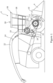
- a forage harvester 2 is shown provided with a front attachment 4 such as a header which contains cutting equipment for cutting and harvesting a crop.
- the cut crop is fed from the header via associated feed rollers 6,8 in a housing 10 to a chopper drum 12 where the crop is chopped into smaller pieces between the chopper drum 12 and an associated shear bar 14.
- the chopped crop passes through a duct 16 and is optionally directed into a cracker unit 18 where the crop is further crushed and threshed.
- the harvested crop is then blown upwards along the duct 16 by an accelerator 20 and exits through a spout 22 directing the processed crop into a trailer or other vehicle moving alongside the forage harvester 2.
- the sensor 24 is conveniently an NIR sensor.
- the sensor 24 is an optical sensor, more preferably a camara.
- the camara may be associated with image analysis software to determine a processed crop property such as a percentage of cracked maize kernels in the processed crop.
- the sensor may be a radar sensor, a lidar sensor or a laser sensor.
- the forage harvester may be further provided with an operator's cab 26.
- a user interface 28 may be located within the operator's cab 26 to communicate information to the operator regarding the operation of the forage harvester.
- the user interface 28 may be provided on an electronic device by way of application software to communicate information to the operator regarding the operation of the forage harvester 2.
- a GPS sensor 30 is provided such that information relating to crop harvested in a previous harvesting process associated with the same location may be retrieved from a stored map.
- a schematic side view illustrates a relationship of example elements for driving first and second cracker rollers 40,42 of the cracker unit 18 in the forage harvester 2.
- the drive arrangement for the cracker unit 18 comprises a drive pulley 44, a tension pulley 46, first and second roller pulleys 48,50 associated with the respective first and second cracker rollers 40,42 and a guide pulley 52.
- a drive belt 54 is located about the rollers of the drive arrangement to define a drive belt path.
- the tensioning pulley 46 is located adjacent the guide belt 54 between the drive pulley 44 and the first roller pulley 48.
- An actuator in the form of a tensioning cylinder 56, is provided to allow movement of the tensioning pulley 46 to allow tensioning of the drive belt 54, by acting on the drive belt 54 between the drive pulley 44 and the first roller pulley 48.
- the guide pulley 52 is located in the drive belt path between the second roller pulley 50 and the drive roller 54. It will be appreciated from Figure 2 that the drive pulley 54 and the guide pulley 52 are located at opposing ends of the loop of the drive belt path.
- the control system 100 comprises a controller 102 having an electronic processor 104, electronic inputs 106, 114, 116 and electronic outputs 108, 110.
- the processor 104 is operable to access a memory 112 of the controller 102 and execute instructions stored therein to perform the steps and functionality described below.
- the processor 104 is operable to receive sensor data via input 106 which, in the illustrated embodiment, takes the form of input signals 105 received from the chute sensor 24.
- the processor 104 is operable to receive data regarding a desired processed crop property via input 114 which, in the illustrated embodiment, takes the form of input signals 113 from the user terminal 26.
- the processor 104 is configured to analyse the input signals and determine therefrom an optimal belt tension to achieve a desired input signal 105 from the chute sensor 24.
- the memory 112 of the controller 102 is provided with a stored relationship between the user terminal input signal and an associated setting value of an actuator, that is the tensioning cylinder 56, in terms of adapting the belt tension in the belt drive to the desired property of the processed crop and to provide instructions to the tensioning cylinder 56.
- the data regarding a desired crop property is preset and retained within the memory 112.
- the processor 104 receives input signals relating to the location of the forage harvester 2, for example by way of a signal from a GPS sensor 30, and the processor 104 uses an input signal 115 from the GPS sensor 30 to retrieve information relating to a processed crop harvested in a previous harvesting process associated with the same location.
- the controller 102 includes an electronic output 108 configured to output control signals 109 generated by the processor 104 for controlling operation of the tensioning cylinder 56.
- processor 104 is operable to generate, and the controller 102 operable to then output via output 108, control signals 109 for controlling operation of the tensioning cylinder 56 in the manner described.
- the controller 102 may output the control signals 109 to a local processing unit of the tensioning cylinder 56 for controlling operation thereof.
- Output 110 is operably coupled to the user interface 28 of the forage harvester 2.
- the control system 100 is operable to control operation of the user interface 28, for example through output of control signals 111 in order to communicate to an operator of the forage harvester information relating to the operation of the control system 100.
- the control system 100 is operable to control the user interface 28 to display to the operator an indicator of the belt tension and/or the desired processed crop property and/or the detected processed crop property.
- the user interface 28 may additionally allow an operator to select or adjust the belt tension in the belt drive of the grain processor, the processor 104 being operable to access the memory 112 of the controller 102 and execute appropriate instructions to adjust the tensioning cylinder 56 as required.
Landscapes
- Life Sciences & Earth Sciences (AREA)
- Environmental Sciences (AREA)
- Harvester Elements (AREA)
Abstract
A forage harvester is disclosed including a grain processor for processing of a chopped crop. The grain processor is driven by a belt drive in which an endless belt has a belt tension, an actuator for adjusting the belt tension in the belt drive and a control device for adjusting the actuator. The control device is configured to control the actuator based on input signals supplied to the control device with regard to a property of the crop and a stored relationship between the signal and an associated setting value of the actuator in terms of adapting the belt tension in the belt drive to the property of the crop. The control device is configured to receive the input signals from a sensor that interacts with the crop upstream of the grain processor and/or taken location-specific from a stored map. The actuator is commanded to adjust the belt tension in the belt drive based on the input signals related to the crop being processed.
Description
- Not applicable.
- The present invention relates to an agricultural harvester, and, in particular, to a forage harvester and improvements relating to the control of the drive system for a grain processor of a forage harvester.
- It is known to provide a forage harvester for harvesting various crops including crops containing grains or corn kernels. Such harvesters may comprise a header apparatus for harvesting a crop, a chopping apparatus for chopping the harvested crop and grain processor for processing of the chopped crop. A control device may be provided for adjusting the degree of processing of the grain processor. The processed crop may be used as fodder for livestock.
- Where the harvested crop is corn or maize, the corn kernels are not digestible in an intact condition. Accordingly, the chopped crop is passed in the grain processor through two or more cracker rollers between which the kernels are opened up or crushed in order to expose the inside of the kernels.
- The degree of processing of the chopped crop, which is related to the belt tension in the drive of the grain processor, determines on the one hand the proportion of broken down or crushed kernels and on the other hand also the energy requirement for operation of the grain processor. However, since these variables present different optimal requirements, the aim is to find a favourable operating point for the grain processor between achieving breaking down of a sufficiently high proportion of the kernels passing through the grain processor and minimising the energy requirement for operation of the grain processor.
- It is an advantage of the present invention that this problem is addressed.
- According to a first aspect of the present invention, a forage harvester comprises a grain processor for processing of a chopped crop, the grain processor being driven by a belt drive in which an endless belt has a belt tension, an actuator for adjusting the belt tension in the belt drive and a control device for adjusting the actuator, the control device being configured to control the actuator based on input signals supplied to the control device with regard to a property of the crop and a stored relationship between the signal and an associated setting value of the actuator in terms of adapting the belt tension in the belt drive to the property of the crop, the control device being configured to receive the input signals from either i) a sensor that interacts with the crop upstream of the grain processor and/or ii) taken location-specific from a stored map and the actuator commanded to adjust the belt tension in the belt drive based on the input signals related to the crop being processed.
- Preferably, the sensor is a NIR sensor.
- Preferably, the sensor is an optical sensor, more preferably a camera.
- Preferably, the sensor is a radar sensor, a lidar sensor or a laser sensor.
- Preferably, where the input signals are taken location-specific from a stored map, this includes information relating to crop harvested in a previous harvesting process from the same location associated with the stored map.
- Preferably, the input signals relate to one or more of the crop density, moisture, proportion of grain, mechanical properties, and colour of the harvested crop.
- Preferably, the forage harvester further comprises a user interface whereby an operator can select a desired belt tension in the belt drive of the grain processor, the control device being configured to control the actuator based upon the desired belt tension.
- Within the scope of this application it should be understood that the various aspects, embodiments, examples and alternatives set out herein, and individual features thereof may be taken independently or in any possible and compatible combination. Where features are described with reference to a single aspect or embodiment, it should be understood that such features are applicable to all aspects and embodiments unless otherwise stated or where such features are incompatible.
- The invention will now be described, by way of example only, with reference to the accompanying drawings, in which:
-
FIG 1 shows a schematic side view of a forage harvester in accordance with the present invention; -
FIG 2 shows a schematic side view of a belt drive for use with the forage harvester ofFIG 1 ; and -
FIG 3 shows a schematic diagram illustrating an embodiment of a control system for a forage harvester in accordance with the invention. - The invention will now be described in the following detailed description with reference to the drawings, wherein preferred embodiments are described in detail to enable practice of the invention. Although the invention is described with reference to these specific preferred embodiments, it will be understood that the invention is not limited to these preferred embodiments. But to the contrary, the invention includes numerous alternatives, modifications and equivalents as will become apparent from consideration of the following detailed description.
- With reference to
Figure 1 , aforage harvester 2 is shown provided with afront attachment 4 such as a header which contains cutting equipment for cutting and harvesting a crop. The cut crop is fed from the header via associatedfeed rollers 6,8 in ahousing 10 to achopper drum 12 where the crop is chopped into smaller pieces between thechopper drum 12 and an associatedshear bar 14. The chopped crop passes through aduct 16 and is optionally directed into acracker unit 18 where the crop is further crushed and threshed. The harvested crop is then blown upwards along theduct 16 by anaccelerator 20 and exits through aspout 22 directing the processed crop into a trailer or other vehicle moving alongside theforage harvester 2. - A
sensor 24, downstream of the processing equipment, preferably located within thespout 22, detects one or more properties of the crop passing through thespout 22. Thesensor 24 is conveniently an NIR sensor. Alternatively, thesensor 24 is an optical sensor, more preferably a camara. The camara may be associated with image analysis software to determine a processed crop property such as a percentage of cracked maize kernels in the processed crop. Alternatively, the sensor may be a radar sensor, a lidar sensor or a laser sensor. - The forage harvester may be further provided with an operator's
cab 26. Auser interface 28 may be located within the operator'scab 26 to communicate information to the operator regarding the operation of the forage harvester. Alternatively, or additionally, theuser interface 28 may be provided on an electronic device by way of application software to communicate information to the operator regarding the operation of theforage harvester 2. - Alternatively, or additionally, a
GPS sensor 30 is provided such that information relating to crop harvested in a previous harvesting process associated with the same location may be retrieved from a stored map. - With reference to
Figure 2 , a schematic side view illustrates a relationship of example elements for driving first andsecond cracker rollers cracker unit 18 in theforage harvester 2. The drive arrangement for thecracker unit 18 comprises adrive pulley 44, atension pulley 46, first andsecond roller pulleys second cracker rollers guide pulley 52. Adrive belt 54 is located about the rollers of the drive arrangement to define a drive belt path. Thetensioning pulley 46 is located adjacent theguide belt 54 between thedrive pulley 44 and thefirst roller pulley 48. An actuator, in the form of a tensioningcylinder 56, is provided to allow movement of thetensioning pulley 46 to allow tensioning of thedrive belt 54, by acting on thedrive belt 54 between thedrive pulley 44 and thefirst roller pulley 48. Theguide pulley 52 is located in the drive belt path between thesecond roller pulley 50 and thedrive roller 54. It will be appreciated fromFigure 2 that thedrive pulley 54 and theguide pulley 52 are located at opposing ends of the loop of the drive belt path. - Other drive arrangements may be provided for in which a tensioning cylinder is used to position a tensioning pully to affect the tension in an endless drive belt.
- Generally, it is understood that increased torque requirements on the pulleys require higher tensioning to avoid belt slippage. Accordingly, higher humidity of the processed crop can be achieved by increasing the belt tension, and greater crop throughput can be achieved by increasing the belt tension to avoid belt slippage. The more kernels the harvested crop contains, the more tensioning must be provided to ensure that each kernel is safely cracked. Further when considering the harvested crop as a whole, different crop consistency for example due to the hardness of the kernels, the planting density of the crop to be harvested and the maturity of the harvested crop will require modifications to the belt tension to achieve the desired quality from the processed crop.
- Turning to
Fig 3 , an embodiment of acontrol system 100 for a drive arrangement of theforage harvester 2 is shown. Thecontrol system 100 comprises acontroller 102 having anelectronic processor 104,electronic inputs electronic outputs processor 104 is operable to access amemory 112 of thecontroller 102 and execute instructions stored therein to perform the steps and functionality described below. - The
processor 104 is operable to receive sensor data viainput 106 which, in the illustrated embodiment, takes the form ofinput signals 105 received from thechute sensor 24. Theprocessor 104 is operable to receive data regarding a desired processed crop property viainput 114 which, in the illustrated embodiment, takes the form ofinput signals 113 from theuser terminal 26. Utilising these input signals, theprocessor 104 is configured to analyse the input signals and determine therefrom an optimal belt tension to achieve a desiredinput signal 105 from thechute sensor 24. In particular, thememory 112 of thecontroller 102 is provided with a stored relationship between the user terminal input signal and an associated setting value of an actuator, that is thetensioning cylinder 56, in terms of adapting the belt tension in the belt drive to the desired property of the processed crop and to provide instructions to the tensioningcylinder 56. - In an alternative embodiment the data regarding a desired crop property is preset and retained within the
memory 112. For example, theprocessor 104 receives input signals relating to the location of theforage harvester 2, for example by way of a signal from aGPS sensor 30, and theprocessor 104 uses aninput signal 115 from theGPS sensor 30 to retrieve information relating to a processed crop harvested in a previous harvesting process associated with the same location. - As described above, the
controller 102 includes anelectronic output 108 configured to output control signals 109 generated by theprocessor 104 for controlling operation of thetensioning cylinder 56. Specifically,processor 104 is operable to generate, and thecontroller 102 operable to then output viaoutput 108, control signals 109 for controlling operation of thetensioning cylinder 56 in the manner described. As will be appreciated, thecontroller 102 may output the control signals 109 to a local processing unit of thetensioning cylinder 56 for controlling operation thereof. -
Output 110 is operably coupled to theuser interface 28 of theforage harvester 2. Here, thecontrol system 100 is operable to control operation of theuser interface 28, for example through output ofcontrol signals 111 in order to communicate to an operator of the forage harvester information relating to the operation of thecontrol system 100. Specifically, thecontrol system 100 is operable to control theuser interface 28 to display to the operator an indicator of the belt tension and/or the desired processed crop property and/or the detected processed crop property. - The
user interface 28 may additionally allow an operator to select or adjust the belt tension in the belt drive of the grain processor, theprocessor 104 being operable to access thememory 112 of thecontroller 102 and execute appropriate instructions to adjust thetensioning cylinder 56 as required. - All references cited herein are incorporated herein in their entireties. If there is a conflict between definitions herein and in an incorporated reference, the definition herein shall control.
- From reading the present disclosure, other modifications will be apparent to persons skilled in the art. Such modifications may involve other features which are already known in the field of forage harvesters and component parts therefore and which may be used instead of or in addition to features already described herein.
Claims (7)
- A forage harvester comprises a grain processor for processing of a chopped crop, the grain processor being driven by a belt drive in which an endless belt has a belt tension, an actuator for adjusting the belt tension in the belt drive and a control device for adjusting the actuator, the control device being configured to control the actuator based on input signals supplied to the control device with regard to a property of the crop and a stored relationship between the signal and an associated setting value of the actuator in terms of adapting the belt tension in the belt drive to the property of the crop, the control device being configured to receive the input signals from either i) a sensor that interacts with the crop upstream of the grain processor and/or ii) taken location-specific from a stored map and the actuator commanded to adjust the belt tension in the belt drive based on the input signals related to the crop being processed.
- A forage harvester according to claim 1, characterised in that the sensor is a NIR sensor.
- A forage harvester according to claim 1, characterised in that the sensor is an optical sensor, more preferably a camera.
- A forage harvester according to claim 1, characterised in that the sensor is a radar sensor, a lidar sensor or a laser sensor.
- A forage harvester according to claim 1, characterised in that where the input signals are taken location-specific from a stored map, this includes information relating to crop harvested in a previous harvesting process from the same location associated with the stored map.
- A forage harvester according to claim 1, characterised in that the input signals relate to one or more of the crop density, moisture, proportion of grain, mechanical properties, colour of the harvested crop.
- A forage harvester according to claim 1, characterised in that the forage harvester further comprises a user interface whereby an operator can select a desired belt tension in the belt drive of the grain processor, the control device being configured to control the actuator based upon the desired belt tension.
Applications Claiming Priority (1)
| Application Number | Priority Date | Filing Date | Title |
|---|---|---|---|
| GBGB2306710.1A GB202306710D0 (en) | 2023-05-05 | 2023-05-05 | Agricultural harvester |
Publications (1)
| Publication Number | Publication Date |
|---|---|
| EP4458129A1 true EP4458129A1 (en) | 2024-11-06 |
Family
ID=86763225
Family Applications (1)
| Application Number | Title | Priority Date | Filing Date |
|---|---|---|---|
| EP24165344.3A Pending EP4458129A1 (en) | 2023-05-05 | 2024-03-21 | Agricultural harvester |
Country Status (3)
| Country | Link |
|---|---|
| US (1) | US20240365707A1 (en) |
| EP (1) | EP4458129A1 (en) |
| GB (1) | GB202306710D0 (en) |
Citations (5)
| Publication number | Priority date | Publication date | Assignee | Title |
|---|---|---|---|---|
| EP1649739A1 (en) * | 2004-10-22 | 2006-04-26 | CNH Belgium N.V. | Belt tensioning mechanism. |
| EP2595468B1 (en) * | 2010-07-22 | 2016-04-06 | AGCO International GmbH | Cracker roller assembly |
| EP3542610A1 (en) * | 2018-03-23 | 2019-09-25 | CLAAS Selbstfahrende Erntemaschinen GmbH | Forage harvester |
| DE102019123947A1 (en) * | 2019-03-27 | 2020-10-01 | Claas Selbstfahrende Erntemaschinen Gmbh | Self-propelled forage harvester and methods of harvesting using a forage harvester |
| DE102021113838A1 (en) * | 2021-05-28 | 2022-12-01 | Deere & Company | Forage harvester with predictive control of the processing level of a grain processor |
-
2023
- 2023-05-05 GB GBGB2306710.1A patent/GB202306710D0/en not_active Ceased
-
2024
- 2024-03-21 EP EP24165344.3A patent/EP4458129A1/en active Pending
- 2024-04-05 US US18/627,821 patent/US20240365707A1/en active Pending
Patent Citations (5)
| Publication number | Priority date | Publication date | Assignee | Title |
|---|---|---|---|---|
| EP1649739A1 (en) * | 2004-10-22 | 2006-04-26 | CNH Belgium N.V. | Belt tensioning mechanism. |
| EP2595468B1 (en) * | 2010-07-22 | 2016-04-06 | AGCO International GmbH | Cracker roller assembly |
| EP3542610A1 (en) * | 2018-03-23 | 2019-09-25 | CLAAS Selbstfahrende Erntemaschinen GmbH | Forage harvester |
| DE102019123947A1 (en) * | 2019-03-27 | 2020-10-01 | Claas Selbstfahrende Erntemaschinen Gmbh | Self-propelled forage harvester and methods of harvesting using a forage harvester |
| DE102021113838A1 (en) * | 2021-05-28 | 2022-12-01 | Deere & Company | Forage harvester with predictive control of the processing level of a grain processor |
Also Published As
| Publication number | Publication date |
|---|---|
| GB202306710D0 (en) | 2023-06-21 |
| US20240365707A1 (en) | 2024-11-07 |
Similar Documents
| Publication | Publication Date | Title |
|---|---|---|
| US9516812B2 (en) | Combine harvester having a driver assistance system | |
| EP2781975B1 (en) | Harvester with fuzzy control system for detecting steady crop processing state | |
| US12527254B2 (en) | Control of a chopper arrangement for an agricultural harvester | |
| US7001267B2 (en) | Method of controlling a threshing mechanism of a combine harvester | |
| US6863604B2 (en) | Method and apparatus for determining optimal adjustments of work units in an agricultural harvesting machine | |
| US7630809B2 (en) | Method for controlling a harvesting machine | |
| EP1671530B1 (en) | Harvesting machine | |
| EP2232978B1 (en) | Forage harvester | |
| US6119442A (en) | Combine setting autoadjust with machine vision | |
| US11785889B2 (en) | System and method for determining an indicator of processing quality of an agricultural harvested material | |
| US20120123650A1 (en) | Agricultural harvesting machine | |
| US12052949B2 (en) | Agricultural harvesting machine, and method for operating an agricultural harvesting machine | |
| CN108135131B (en) | Mapping system, mapping device and computer program | |
| US11109535B2 (en) | Combine harvester including a feeder house with a lower deflection roller | |
| BE1029377B1 (en) | Forage harvester with predictive control of the processing level of a grain processor | |
| US11944036B2 (en) | Forage harvester | |
| US20240215484A1 (en) | Residue Chopper and Spreader Arrangement | |
| US20240365707A1 (en) | Agricultural Harvester | |
| US20250221337A1 (en) | Devices and methods for automated concave covers | |
| Hanna et al. | Grain harvesting machinery design | |
| US20260007103A1 (en) | Forage Harvester | |
| US20250127084A1 (en) | Harvesting Machine Monitoring | |
| US20250000024A1 (en) | Corn ear size detection | |
| EP4212005B1 (en) | A residue collector | |
| EP4353069B1 (en) | Stubble lean detection system for an agricultural harvester |
Legal Events
| Date | Code | Title | Description |
|---|---|---|---|
| PUAI | Public reference made under article 153(3) epc to a published international application that has entered the european phase |
Free format text: ORIGINAL CODE: 0009012 |
|
| STAA | Information on the status of an ep patent application or granted ep patent |
Free format text: STATUS: THE APPLICATION HAS BEEN PUBLISHED |
|
| AK | Designated contracting states |
Kind code of ref document: A1 Designated state(s): AL AT BE BG CH CY CZ DE DK EE ES FI FR GB GR HR HU IE IS IT LI LT LU LV MC ME MK MT NL NO PL PT RO RS SE SI SK SM TR |
|
| STAA | Information on the status of an ep patent application or granted ep patent |
Free format text: STATUS: REQUEST FOR EXAMINATION WAS MADE |
|
| 17P | Request for examination filed |
Effective date: 20250506 |