EP4456788B1 - Tragbare vorrichtung zur kontinuierlichen überwachung von gesundheitsparametern - Google Patents
Tragbare vorrichtung zur kontinuierlichen überwachung von gesundheitsparametern Download PDFInfo
- Publication number
- EP4456788B1 EP4456788B1 EP22844558.1A EP22844558A EP4456788B1 EP 4456788 B1 EP4456788 B1 EP 4456788B1 EP 22844558 A EP22844558 A EP 22844558A EP 4456788 B1 EP4456788 B1 EP 4456788B1
- Authority
- EP
- European Patent Office
- Prior art keywords
- sweat
- sensor
- lactate
- wearable device
- biomarker
- Prior art date
- Legal status (The legal status is an assumption and is not a legal conclusion. Google has not performed a legal analysis and makes no representation as to the accuracy of the status listed.)
- Active
Links
Images


Classifications
-
- A—HUMAN NECESSITIES
- A61—MEDICAL OR VETERINARY SCIENCE; HYGIENE
- A61B—DIAGNOSIS; SURGERY; IDENTIFICATION
- A61B5/00—Measuring for diagnostic purposes; Identification of persons
- A61B5/02—Detecting, measuring or recording for evaluating the cardiovascular system, e.g. pulse, heart rate, blood pressure or blood flow
- A61B5/0205—Simultaneously evaluating both cardiovascular conditions and different types of body conditions, e.g. heart and respiratory condition
-
- A—HUMAN NECESSITIES
- A61—MEDICAL OR VETERINARY SCIENCE; HYGIENE
- A61B—DIAGNOSIS; SURGERY; IDENTIFICATION
- A61B5/00—Measuring for diagnostic purposes; Identification of persons
- A61B5/0002—Remote monitoring of patients using telemetry, e.g. transmission of vital signals via a communication network
-
- A—HUMAN NECESSITIES
- A61—MEDICAL OR VETERINARY SCIENCE; HYGIENE
- A61B—DIAGNOSIS; SURGERY; IDENTIFICATION
- A61B5/00—Measuring for diagnostic purposes; Identification of persons
- A61B5/02—Detecting, measuring or recording for evaluating the cardiovascular system, e.g. pulse, heart rate, blood pressure or blood flow
- A61B5/024—Measuring pulse rate or heart rate
-
- A—HUMAN NECESSITIES
- A61—MEDICAL OR VETERINARY SCIENCE; HYGIENE
- A61B—DIAGNOSIS; SURGERY; IDENTIFICATION
- A61B5/00—Measuring for diagnostic purposes; Identification of persons
- A61B5/145—Measuring characteristics of blood in vivo, e.g. gas concentration or pH-value ; Measuring characteristics of body fluids or tissues, e.g. interstitial fluid or cerebral tissue
- A61B5/14507—Measuring characteristics of blood in vivo, e.g. gas concentration or pH-value ; Measuring characteristics of body fluids or tissues, e.g. interstitial fluid or cerebral tissue specially adapted for measuring characteristics of body fluids other than blood
- A61B5/14517—Measuring characteristics of blood in vivo, e.g. gas concentration or pH-value ; Measuring characteristics of body fluids or tissues, e.g. interstitial fluid or cerebral tissue specially adapted for measuring characteristics of body fluids other than blood for sweat
-
- A—HUMAN NECESSITIES
- A61—MEDICAL OR VETERINARY SCIENCE; HYGIENE
- A61B—DIAGNOSIS; SURGERY; IDENTIFICATION
- A61B5/00—Measuring for diagnostic purposes; Identification of persons
- A61B5/145—Measuring characteristics of blood in vivo, e.g. gas concentration or pH-value ; Measuring characteristics of body fluids or tissues, e.g. interstitial fluid or cerebral tissue
- A61B5/14532—Measuring characteristics of blood in vivo, e.g. gas concentration or pH-value ; Measuring characteristics of body fluids or tissues, e.g. interstitial fluid or cerebral tissue for measuring glucose, e.g. by tissue impedance measurement
-
- A—HUMAN NECESSITIES
- A61—MEDICAL OR VETERINARY SCIENCE; HYGIENE
- A61B—DIAGNOSIS; SURGERY; IDENTIFICATION
- A61B5/00—Measuring for diagnostic purposes; Identification of persons
- A61B5/145—Measuring characteristics of blood in vivo, e.g. gas concentration or pH-value ; Measuring characteristics of body fluids or tissues, e.g. interstitial fluid or cerebral tissue
- A61B5/14546—Measuring characteristics of blood in vivo, e.g. gas concentration or pH-value ; Measuring characteristics of body fluids or tissues, e.g. interstitial fluid or cerebral tissue for measuring analytes not otherwise provided for, e.g. ions, cytochromes
-
- A—HUMAN NECESSITIES
- A61—MEDICAL OR VETERINARY SCIENCE; HYGIENE
- A61B—DIAGNOSIS; SURGERY; IDENTIFICATION
- A61B5/00—Measuring for diagnostic purposes; Identification of persons
- A61B5/42—Detecting, measuring or recording for evaluating the gastrointestinal, the endocrine or the exocrine systems
- A61B5/4261—Evaluating exocrine secretion production
- A61B5/4266—Evaluating exocrine secretion production sweat secretion
-
- A—HUMAN NECESSITIES
- A61—MEDICAL OR VETERINARY SCIENCE; HYGIENE
- A61B—DIAGNOSIS; SURGERY; IDENTIFICATION
- A61B5/00—Measuring for diagnostic purposes; Identification of persons
- A61B5/48—Other medical applications
- A61B5/4869—Determining body composition
- A61B5/4875—Hydration status, fluid retention of the body
-
- A—HUMAN NECESSITIES
- A61—MEDICAL OR VETERINARY SCIENCE; HYGIENE
- A61B—DIAGNOSIS; SURGERY; IDENTIFICATION
- A61B5/00—Measuring for diagnostic purposes; Identification of persons
- A61B5/68—Arrangements of detecting, measuring or recording means, e.g. sensors, in relation to patient
- A61B5/6801—Arrangements of detecting, measuring or recording means, e.g. sensors, in relation to patient specially adapted to be attached to or worn on the body surface
- A61B5/683—Means for maintaining contact with the body
- A61B5/6832—Means for maintaining contact with the body using adhesives
- A61B5/6833—Adhesive patches
-
- A—HUMAN NECESSITIES
- A61—MEDICAL OR VETERINARY SCIENCE; HYGIENE
- A61B—DIAGNOSIS; SURGERY; IDENTIFICATION
- A61B2503/00—Evaluating a particular growth phase or type of persons or animals
- A61B2503/10—Athletes
-
- A—HUMAN NECESSITIES
- A61—MEDICAL OR VETERINARY SCIENCE; HYGIENE
- A61B—DIAGNOSIS; SURGERY; IDENTIFICATION
- A61B2562/00—Details of sensors; Constructional details of sensor housings or probes; Accessories for sensors
- A61B2562/02—Details of sensors specially adapted for in-vivo measurements
- A61B2562/0219—Inertial sensors, e.g. accelerometers, gyroscopes, tilt switches
-
- A—HUMAN NECESSITIES
- A61—MEDICAL OR VETERINARY SCIENCE; HYGIENE
- A61B—DIAGNOSIS; SURGERY; IDENTIFICATION
- A61B5/00—Measuring for diagnostic purposes; Identification of persons
- A61B5/02—Detecting, measuring or recording for evaluating the cardiovascular system, e.g. pulse, heart rate, blood pressure or blood flow
- A61B5/024—Measuring pulse rate or heart rate
- A61B5/02438—Measuring pulse rate or heart rate with portable devices, e.g. worn by the patient
-
- A—HUMAN NECESSITIES
- A61—MEDICAL OR VETERINARY SCIENCE; HYGIENE
- A61B—DIAGNOSIS; SURGERY; IDENTIFICATION
- A61B5/00—Measuring for diagnostic purposes; Identification of persons
- A61B5/68—Arrangements of detecting, measuring or recording means, e.g. sensors, in relation to patient
- A61B5/6801—Arrangements of detecting, measuring or recording means, e.g. sensors, in relation to patient specially adapted to be attached to or worn on the body surface
- A61B5/683—Means for maintaining contact with the body
- A61B5/6831—Straps, bands or harnesses
Definitions
- the present invention belongs to the technical filed of medical devices, in particular to the area of wearable medical devices both for clinical and sport applications.
- An object of the invention is the provision of a multi-sensor device for the continuous remote, and real-time monitoring of health condition of patients or sport persons, without blood extraction and a method thereof.
- the invention can advantageously be used in sports medicine and/or sports health sectors for remote effort and/or fatigue assessment.
- Blood tests are the reference clinical methods that show the most important physiological parameters that allow an accurate diagnosis of a patient's condition.
- the analysis of most of the metabolites of interest requires blood collection, creating an obstacle for their use in real-time monitoring in both clinical health and sports medicine.
- wearable devices that can be worn by a user to continuously monitor an individual's activities, such as walking or running without unduly interrupting or limiting those activities.
- These wearable devices include electronics, and physiological sensors configured to sense certain physiological parameters of the wearer, such as heart rate, as well as motion sensors, GPS, etc.
- WO 2010/045247 A1 discloses a sweat glucose sensor for determining the glucose concentration in a volume of sweat.
- the sweat glucose sensor may comprise two or more electrodes in contact with sweat in a container defined by two or more layers of a skin patch.
- the container may additionally contain a glucose enzyme that reacts with glucose in sweat collected by the container. The reaction of the glucose in the sweat with the glucose enzyme may affect an electrical signal passed by the two or more electrodes. The electrical signal may then be used to determine a sweat glucose concentration.
- the sweat glucose sensor may comprise two or more fill electrodes, also positioned to contact sweat collected by the container. The fill electrodes may be used, for example, to determine whether the skin patch contains a requisite volume of sweat to perform an accurate glucose measurement.
- Devices, methods, and kits for collecting sweat that has come to a skin surface are also disclosed.
- US 2020/397315 A1 discloses a system for collecting and analyzing sweat includes a sweat sensing device having at least one sensor configured to sense one of physiologic information, biologic information, biochemical information, and biometric information, from skin of a person to whom the sweat sensing device is attached.
- a wireless transmitter is mounted to the sweat sensing device and electrically connected to the at least one sensor.
- US 2018/020966 A1 discloses sweat sensing devices configured to periodically measure sweat conductivity and galvanic skin response, devices to measure volumetric sweat flow rate, and devices that combine the three functions.
- the vital-signs or signs sensors is one or more of the following sensors: a heart rate sensor, a respiratory rate sensor, a blood pressure sensor, a body temperature sensor, and an oxygen saturation sensor.
- the wearable device of the invention is a smart wearable device for lactate monitoring, that integrates a microfluidic system that ensures efficient sweat capture and continuous circulation of a fresh sweat sample.
- the invention is capable of providing real time health status of athletes and report when an athlete enters the anaerobic phase, thus, creating a new paradigm in sports training planning, as well as the health status of the athlete.
- the processing unit is integrally contained in the main housing, but in other preferred embodiments of the invention, the processing unit or part of it, is external to the device, for example, it is implemented in a smart phone, a smart watch, a tablet or similar devices.
- the main housing additionally includes a power source like a battery, for supplying power to the electronics implementing the processing unit, and electric connectors for the communication with the consumable part.
- the flexible band is fitted with at least one biosensor for measuring a vital-sign or physiological sign of the user, such as a heart rate sensor, thus, in addition to the sweat measurements, heart rate measurements are also taken in direct contact with the skin, with the same de device, and simultaneously as the sweat parameters are measured.
- a biosensor for measuring a vital-sign or physiological sign of the user such as a heart rate sensor
- the flexible band is implemented as an elastic textile tape that would have a good hold on the body and would contain a pair of electrodes to measure the heart rate.
- the electrodes are made of bioelectric silicone to capture the electrocardiogram signal and extract the heart rate. They have sufficient conductivity to obtain a quality heart rate signal and are resistant to continuous use and washing.
- the flexible band can be provided with other sensors, like a respiratory rate sensor to obtain additional parameters.
- the consumable component has a contact surface provided to be in contact with the user's skin when the main housing is attached to a user's body part, and the consumable component is coupled with the main body.
- the means for attaching the main housing to a part of a user's body comprises an adhesive material for example an adhesive surface suitable to be adhered on a user's skin.
- this adhesive surface is provided on a surface of the consumable component meant to be in contact with the user's skin.
- the consumable component incorporates: the sweat collection inlet formed in the consumable component's contact surface at least one sweat sensor, the sweat rate measuring device, and the microfluidic channel, and electric connection means for electrically connecting the consumable component with the processing unit when the consumable component is coupled with the main housing.
- the consumable component is a generally flat body embodied as a cardlike component.
- the main housing has a front surface and a back surface provided with a pair of guides opposite each other, and the consumable component has a pair of sides wings, such that the consumable component is couplable with the main housing by inserting its side wings respectively in the guides and by moving the consumable component on the back surface of the main housing.
- the main body is provided by a pair of electric connectors and each end of the flexible band is fitted with metallic connectors for mechanically and electrically connecting the flexible band and the biosensor with the main body.
- the main body includes a battery for supplying power to the processing unit, and the main body has a lid at its back surface for providing access to the battery.
- the consumable component is overlapped with the lid when the consumable component is operatively coupled with the main housing.
- the wearable device provides an advanced and integral personalized health management capability, through the combined analysis of key metabolic and physiological health indicators, like blood glucose measurement data, in addition to heart rate, oxygen saturation and temperature measurements, to achieve accurate equivalence with blood glucose measurements.
- key metabolic and physiological health indicators like blood glucose measurement data, in addition to heart rate, oxygen saturation and temperature measurements, to achieve accurate equivalence with blood glucose measurements.
- the main application is focused on sports medicine or sports health sector, for example for monitoring dehydration monitoring in athletes, but depending on the combination of sensors used, the device can be adapted to different applications as explained below.
- the wearable device is adapted to operate as a device for dehydration monitoring in athletes.
- a combination of sensors for measuring sweating, conductivity and some salt such as sodium can give real-time information on the state of dehydration of an athlete during physical exertion. Important to improve the control of dehydration in tests, and to be able to be treated in time (as an alarm system for the user) and with measurable variables in order to create an objective scale.
- the wearable device comprises a heart rate and sweat rate measurement sensors, and the device is adapted to operate as a device for monitoring user fatigue.
- the wearable device is adapted to operate as a device for nocturnal hypoglycaemia monitoring.
- the device is a non-invasive device provided with sensors for measuring: heart rate, sweating, conductivity and a glucose sensor adapted to low ranges. The user would put the device on during the night, and the device can generate alarms when an episode of this type is detected. With the addition of predictive models, the onset of an episode could be predicted in advance to prevent and limit its consequences.
- the wearable device is adapted to operate as a device for peritoneal dialysis remote monitoring.
- the device comprises a heart rate sensor, an accelerometer, a sweat rate sensor, and sensors for measuring: conductivity, ions such as sodium, and lactate.
- the present disclosure also relates to a wearable device for continuous monitoring of health parameters of a user.
- the device comprises at least one sweat sensor for measuring a sweat biomarker, a sweat collection inlet arranged in the device for collecting sweat when the device is worn by a user, a microfluidic channel for conveying collected sweat from the inlet to the sweat sensor, at least one vital-sign sensor arranged in the device for measuring a vital-sign or physiological sign of the user, a sweat volume sensor for measuring volume of the collected sweat, and a processing unit adapted for receiving and processing data provided by the sweat sensor, the vital-sign biosensor and the sweat volume sensor.
- the vital-sign sensor comprises at least a heart rate sensor; and the processing unit is further adapted to calculate, preferably by means of machine learning algorithms, the concentration of the biomarker in blood based on data provided by: the sweat biomarker sensor, the sweat volume sensor and heart rate sensor.
- the sweat biomarker sensor is selected from a list comprising: a sweat lactate sensor and a sweat glucose sensor.
- the sweat biomarker sensor is a sweat lactate sensor.
- the sweat biomarker sensor is a sweat lactate sensor
- the processing unit is adapted to calculate, preferably by means of machine learning algorithms, a blood lactate concentration based on data provided by: the sweat lactate sensor, the sweat volume sensor and heart rate sensor.
- the wearable device further comprises a sweat rate sensor
- the processing unit is further adapted for monitoring user fatigue.
- the wearable device further comprises a conductivity sensor and a ion sensor
- the processing unit is further adapted for monitoring dehydration in athletes, based on data provided by the sweat volume sensor, the conductivity sensor and the ion sensor.
- the sweat biomarker sensor is a sweat glucose sensor and further comprising: a conductivity sensor
- the processing unit is adapted to calculate, preferably by means of machine learning algorithms, a blood glucose concentration based on data provided by the heart rate sensor, the sweat volume sensor, the conductivity sensor and the sweat glucose sensor.
- the processing unit is further adapted to monitor the nocturnal hypoglycaemia, based on data provided by the heart rate sensor, the sweat volume sensor, the conductivity sensor and the sweat glucose sensor.
- the sweat glucose sensor is adapted to detect glucose sweat concentrations below 55mg/L.
- sweat biomarker sensor is a sweat lactate sensor and/or a sweat glucose sensor
- the device further comprising an accelerometer, a conductivity sensor, and an ions sensor preferably a sodium sensor
- the processing unit is further adapted to monitor the peritoneal dialysis based on data provided by the heart rate sensor, the accelerometer, the sweat rate sensor, the conductivity sensor, the ions sensor and the sweat lactate sensor and/or the sweat glucose sensor.
- a second aspect of the invention refers to a method for non-invasively determining the concentration of a biomarker in blood, the method comprising:
- the biomarker is selected from a list comprising: lactate and glucose. In another preferred embodiment, the biomarker is lactate.
- the biomarker is lactate and the method comprises determining the blood lactate concentration based on the sweat lactate, the sweat volume and the heart rate.
- the concentration of the biomarker in sweat, the volume of sweat received, and/or the heart rate of the subject are received from a wearable device according to any of the embodiments of the first aspect of the invention.
- the disclosure provides also a method for non-invasively or minimally invasively evaluating the condition of a subject, the method comprising determining the concentration of a biomarker in blood in a non-invasive or minimally invasive way, based on the concentration of such biomarker in sweat.
- the method comprises determining the concentration of the biomarker in blood based on the concentration of such biomarker in sweat, the sweat volume, and the heart rate of the subject.
- the biomarker is selected from a list comprising lactate and glucose. In another preferred embodiment, the biomarker is lactate.
- the concentration of the biomarker in sweat, the volume of sweat received, and/or the heart rate of the subject are received from a wearable device according to any of the embodiments of the first aspect of the invention.
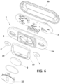
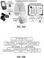
- Figure 1 shows an exemplary embodiment of a wearable device (1) comprising a main housing (2) and a flexible band or strap (3) for attaching the main housing to a part of a user's body, and a pair of electric and mechanic connectors or snap buttons (4) provided in the main housing (2) for mechanically and electrically connecting the flexible band ends with the main housing (2).
- the flexible band (3) is implemented as an elastic textile tape with female connectors at its ends to be coupled with the snap buttons (4).
- the flexible band (3) is fitted conventionally with at least one biosensor for measuring a vital-sign or physiological sign of the user, in a known manner for example a pair of electrodes to measure heart rate.
- the electrodes are made of bioelectric silicone to capture the electrocardiogram signal and extract the heart rate, and they have sufficient conductivity to obtain a quality heart rate signal and are resistant to continuous use and washing.
- the vital-signs or signs sensors are at least one of the following: a heart rate sensor, a respiratory rate sensor, blood pressure sensor, body temperature sensor, and oxygen saturation sensor.
- the device (1) includes a consumable component (5) configured to be manually coupled and uncoupled with the main housing (2), and having a contact surface (6) provided to be in contact with the user's skin when the consumable component (5) is coupled with the main housing (2), and the main housing (2) is attached to a user's body for example by means of the flexible band (3).
- the main housing (2) in particular the base (2a) has a receptacle (8) for receiving a battery (9) for supplying power to the electronic circuit (7), and a lid (10) for closing and opening the receptable (8).
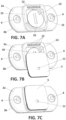
- the consumable component (5) is generally a flat body, and the main housing (2) and the consumable component (5) are configured, such that the consumable component (5) is couplable with the main housing (2) by moving the consumable component (5) on the same lane as the generally flat back surface (19) of the main housing (2) or a plane parallel to it, as illustrated in Figures 2 , 7B and 7C , such that the lid (10) can only be accessed when the consumable component (5) has been taken off from the main housing (2).
- the consumable component (5) is manufactured as a stack of layers of plastic materials where the microfluidic channels are formed by laser cutting or die cutting.
- the integrated sensors are electrochemical in nature and therefore require electrodes that are fabricated by screen printing.
- a set of electric connectors (12) are provided at the back surface (13) of the base (2a) of the main housing (2), in order to realise electric communication between the sensors located in the consumable component (5) and the processing unit (7).
- These connectors (12) are known spring-biased connectors, that stablish electric contact with corresponding electric pads (17) (provided in the consumable component (5), in a known manner when this is coupled with the main housing (2).
- the main housing (2) has a back surface (13) provided with a pair of guides (15) opposite each other, in a way that a space or pocket is formed in between the guides (15) for receiving the consumable component (5) therein.
- the consumable component (5) has a pair of sides wings (16), dimensioned and configured to fit in the space formed in between the guides (15), such that the consumable component (5) is couplable with the main housing (2) by inserting its side wings (16) respectively in the guides (15), and by moving the consumable component on the back surface (13) of the main housing (2) as represented in the sequence of Figures 7A, 7B, and 7C ..
- the sweat volume sensor (18) is represented schematically in Figure 8 , and comprises a microfluidic circuit or a microfluidic reservoir (19), fluidly communicated with the sensing chamber and arranged downstream the sensing chamber (21), such that sweat would enter the inlet (11), and flow along the microfluidic channel (22) and the sensing chamber (21) to gradually fill the reservoir (19), as more clearly represented in Figure 10 .
- the sweat volume sensor (18) comprises a pair of electrodes (20,20') and the microfluidic reservoir (19) arranged in between the two electrodes, such that a capacitance value between the two electrodes is variable depending on the amount of sweat in the reservoir.
- the electrodes (20,20') allow determination of the flow of sweat as it advances filling the reservoir (19) with limited influence of the ionic strength of the sweat sample.
- the local sweat flow for each measurement interval can be estimated (we know the time and volume of sweat advancement) and thus be able to correct the sweat lactate measurement as a dilution factor.
- the two electrodes are a pair of conductive flexible strips opposite each other.
- the consumable component (5) can be manufactured as a stack of layers of plastic materials where the microfluidic channels and sensing chamber are formed by laser cutting or die cutting.
- the integrated sensors are electrochemical in nature, and therefore require electrodes that are fabricated by screen printing.
- the sweat inlet (11), the microfluidic channel (22) and the sensing chamber (21), are placed above the microfluidic reservoir (19).
- the device (1) comprises at least one sweat sensor for measuring a sweat biomarker, a sweat collection inlet (11) arranged in the device for collecting sweat when the device is worn by a user, a microfluidic channel (22) for conveying collected sweat from the inlet to the sweat sensor, at least one vital-sign sensor arranged in the device for measuring a vital-sign or physiological sign of the user, a sweat volume sensor (18) for measuring volume of the collected sweat, and a processing unit (7) adapted for receiving and processing data provided by the sweat sensor, the vital-sign biosensor and the sweat volume sensor (18).
- the vital-sign sensor comprises at least a heart rate sensor; and the processing unit (7) is further adapted to calculate, preferably by means of machine learning algorithms, the concentration of the biomarker in blood based on data provided by: the sweat biomarker sensor, the sweat volume sensor (18) and heart rate sensor.
- the sweat biomarker sensor is selected from a list comprising: a sweat lactate sensor and a sweat glucose sensor.
- the device (1) is configured for monitoring the concentration of lactate and/or glucose in blood based on data provided by the respective sweat biomarker sensor, the sweat volume sensor and heart rate sensor.
- the sweat biomarker sensor is a sweat lactate sensor
- the processing unit is adapted to calculate, preferably by means of machine learning algorithms, a blood lactate concentration based on data provided by: the sweat lactate sensor, the sweat volume sensor and heart rate sensor.
- a second aspect of the invention refers to a method for non-invasively determining the concentration of a biomarker in blood , the method comprising:
- the method may comprise an intermediate step before determining the concentration of the biomarker in blood, comprising computing a standardised value representing the concentration of the biomarker in blood from the computed value of step b).
- the biomarker is selected from a list comprising or consisting of: lactate and glucose.
- the method is for non-invasively determining the concentration of lactate or glucose in blood, such that when the concentration of lactate or glucose in sweat, the volume of sweat received and the heart rate of the subject is received, a value representing the concentration of lactate or glucose in blood can be computed respectively , and it can be finally determined that the computed value is the concentration of lactate in blood or the concentration of glucose in blood, respectively.
- the biomarker is lactate.
- this allows for the non-invasive monitoring of blood-related conditions associated to lactate.
- the determined concentration of lactate in blood from the non-invasive measurement of lactate in sweat, the sweat volume and the heart rate of the subject has not only high correlation with the determined concentration of lactate in blood when measured directly, but the provided values are standardized values for the concentration of lactate in blood.
- the method is for non-invasively determining the concentration of lactate o in blood, such that when the concentration of lactate in sweat, the volume of sweat received and the heart rate of the subject is received, a value representing the concentration of lactate in blood can be computed, and it can be finally determined that the computed value is the concentration of lactate in blood.
- the concentration of such biomarker in sweat, the volume of sweat received and/or the heart rate of the subject is obtained from a device (1) according to any of the embodiments of the first aspect of the invention.
- the present disclosure provides also a method for evaluating the condition of a subject, the method comprising determining the concentration of a biomarker in blood in a non-invasive or minimally invasive way, based on the concentration of such biomarker in sweat.
- the method comprises determining the concentration of a biomarker in blood in a non-invasive or minimally invasive way, based on the concentration of such biomarker in blood, the sweat volume, and the heart rate of the subject. More preferably, the biomarker is lactate or glucose.
- the biomarker is selected from a list comprising or consisting of: lactate and glucose.
- the concentration of such biomarker in sweat, the volume of sweat received and/or the heart rate of the subject is obtained from a device (1) according to any of the embodiments of the first aspect of the invention.
- ELER Exhaustion and Lactate Excretion Rate
- the goal in this study was to test the capability of a multiparametric model of predicting blood lactate with enough accuracy, overcoming the challenges associated to sweat analysis and lactate monitoring, in particular.
- recent wearable technology was used to replicate tools that could be applied in a real scenario combined with the rigorousness of physiological studies.
- the sweat sensors used in this study were characterized initially at the laboratory.
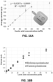
- the sweat lactate sensor was characterized using artificial sweat samples, to replicate the sample matrix and interferents in the sensor response, in the concentration range of interest.
- We could observe that the sweat sensor used could measure up to 40 mM with a good linear response ( Figure 16A ).
- our custom instrumentation provided values comparable to commercial potentiostats (Palmsens) ( Figure 16B ).
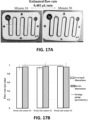
- the sweat volume sensor consisted in a microfluidic patch that collected sweat into a microfluidic channel.
- a dyed paper at the inlet provided colour to the sweat, facilitating the visual determination of the fluid front. Knowing the geometrical dimensions of the microfluidic channel and taking consecutive pictures, the volume of collected sweat for a period of time can be calculated.
- the variable used in the model, instantaneous sweat rate, was calculated from the increment in volume for a given period of time.
- Figure 17A an in vivo example of the working mechanism of the sensor can be seen.
- In vitro calibration of this sensor consisted in injecting water using a syringe pump and comparing the flow rate against the set one ( Figure 17B ). It was also validated that the fabrication method, laser cutting, was replicable enough because there was no significant difference for flow rate calculation when using the averaged dimensions of the microfluidic channel or the individual ones.
- the analysis process started by extracting data from the sensors.
- For the sweat lactate measurements the averaged current of the stable region of the chronoamperometry was used directly, as its proportionality with lactic acid concentration had been previously demonstrated ( Fig. 16 ).
- For the sweat rate measurements the procedure described for in vitro characterization was applied.
- the heart rate was extracted from the heart rate monitor source for the same test time as the rest of measurements.
- the lactate Excretion Rate (LER) is the product of the sweat lactate concentration and the sweat rate to account for volume dilution.
- the LER was divided by the heart rate (HR) to create the ELER (Exertion and Lactate Excretion Rate) parameter as a way to introduce the expected relation between independent variables.
- the purpose the ELER parameter is to provide the models with an initial logical relation between independent variables. On the contrary, if the relation is not present in the data, model performance would be reduced.
- Pre-processing for all models used consisted in centring and scaling for all continuous variable in order to have a mean of 0 and a standard deviation 1. This way, the numerical stability is improved and continuous variables of different values can be used together.
- the initial set of models used for the prediction of blood lactate are multiparametric linear models including LM (Linear Models), PLS (Partial Least Squares) or PCR (Principal Component Regression). Due to the complexity of the data, it is expected that non-linearity must be included through the use of a neural network algorithm (MLP, MultiLayer Perceptron).
- MLP MultiLayer Perceptron
- MLP The structure of MLP consists in an input layer (independent variables), a hidden layer and the output layer (dependent variable). MLP just have a single hidden layer with neurons (hidden units) which are mathematical expressions consisting of weighted inputs (obtained from supervised back-propagation training) that produce an output only above a certain threshold. This threshold is controlled by the activation function (which can be of different nature) which is the non-linearity term added to the model. MLP used is from the package caret in R, the number of neurons in the hidden layer was tuned (from 1 to 10, 5 neurons were the final optimized number) and the activation function used was the rectified linear function.
- RMSE Root Mean Square Error
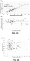
- Fig. 18A Shows a correlation plot between Lactate Plus (portable meter and test strips) and Diaglobal (optical instrument) for blood lactate.
- Fig. 18B shows a Bland-Altman plot showing the agreement between methodologies.
- the first step consisted in finding the relationship between blood lactate and sweat lactate.
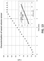
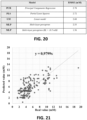
- a simple correlation plot was enough to see that direct correlation was not feasible, see Fig. 19 , and that multiparametric approaches must be used.
- the first set of models applied were multiparametric regression models: PCR, PLS and LM.
- RSME values can be seen in Fig. 20 . All these algorithms are linear, therefore allowing for simpler, less computing intensive predictions. However, the performance obtained initially was not satisfactory enough to use them as a reliable tool for the blood lactate prediction. Not only in the accuracy (reflected by the RMSE value), but the prediction robustness was not reproducible at all, depending greatly on the training data used. On the other hand, MLP showed a robust prediction with minimal variation to training data, as well as an increase in prediction accuracy.
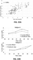
- FIG. 21 A correlation plot of multiple predictions combined using MLP algorithm is shown in Fig. 21 . It can be clearly seen how high blood lactate values are scarce in our dataset and have the least accurate predictions. Besides, the relevance in predicting values of lactate over 10 mM is limited as the athlete would be far past the anaerobic threshold. Therefore, filtering out the high blood lactate values, the prediction performance notably increased as shown in Figure 22A . Not only in absolute terms as it can be seen in the RMSE value (reduced up to 1.56 mM, much closer to the 1.3 mM reference stated previously), but in the capability to follow the temporal evolution of the blood lactate for a given user ( Figure 22B ).
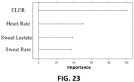
- a meaningful characteristic of the MLP model used is the relative importance of each independent variable in the prediction ( Fig. 23 ).
- the most important parameter was found to be ELER, the derived parameter from the rest of measurements, confirming that the relationship envisioned was correct.
- the next variables, in terms of importance, were the individual measurements of heart rate, sweat lactate and sweat rate.
Landscapes
- Health & Medical Sciences (AREA)
- Life Sciences & Earth Sciences (AREA)
- Physics & Mathematics (AREA)
- Engineering & Computer Science (AREA)
- Medical Informatics (AREA)
- Biomedical Technology (AREA)
- Public Health (AREA)
- General Health & Medical Sciences (AREA)
- Pathology (AREA)
- Surgery (AREA)
- Animal Behavior & Ethology (AREA)
- Molecular Biology (AREA)
- Heart & Thoracic Surgery (AREA)
- Veterinary Medicine (AREA)
- Biophysics (AREA)
- Physiology (AREA)
- Optics & Photonics (AREA)
- Cardiology (AREA)
- Endocrinology (AREA)
- Gastroenterology & Hepatology (AREA)
- Emergency Medicine (AREA)
- Computer Networks & Wireless Communication (AREA)
- Pulmonology (AREA)
- Measuring And Recording Apparatus For Diagnosis (AREA)
- Measurement Of The Respiration, Hearing Ability, Form, And Blood Characteristics Of Living Organisms (AREA)
- Data Mining & Analysis (AREA)
- Investigating Or Analysing Biological Materials (AREA)
- Theoretical Computer Science (AREA)
- Software Systems (AREA)
- Artificial Intelligence (AREA)
- Computer Vision & Pattern Recognition (AREA)
- Evolutionary Computation (AREA)
- Primary Health Care (AREA)
- Computing Systems (AREA)
- General Engineering & Computer Science (AREA)
- General Physics & Mathematics (AREA)
- Mathematical Physics (AREA)
- Epidemiology (AREA)
- Databases & Information Systems (AREA)
Claims (15)
- Tragbare Vorrichtung (1) zur kontinuierlichen Überwachung von Gesundheitsparametern eines Benutzers, wobei die Vorrichtung (1) Folgendes umfasst:mindestens einen Schweißsensor zum Messen eines Schweißbiomarkers,einen Schweißsammeleinlass (11), welcher in der Vorrichtung (1) angeordnet ist, um Schweiß zu sammeln, wenn die Vorrichtung (1) von einem Benutzer getragen wird,einen mikrofluidischen Kanal (22) zum Fördern des gesammelten Schweißes vom Einlass zum Schweißsensor,mindestens einen Vitalzeichensensor, welcher in der Vorrichtung (1) angeordnet ist, zum Messen eines Vitalzeichens oder physiologischen Zeichens des Benutzers,einen Schweißvolumensensor (18) zum Messen des Volumens des gesammelten Schweißes, undeine Verarbeitungseinheit (7), welche dazu angepasst ist, Daten, welche vom Schweißbiomarkersensor, vom Vitalzeichenbiosensor und vom Schweißvolumensensor (18) bereitgestellt werden, zu empfangen und zu verarbeiten;wobei der Vitalzeichensensor mindestens einen Herzfrequenzsensor umfasst;
undwobei der Schweißbiomarkersensor ein Schweißlaktatsensor ist und wobei die Verarbeitungseinheit (7) zusätzlich dazu angepasst ist, vorzugsweise mittels Algorithmen für maschinelles Lernen, eine Blutlaktatkonzentration zu berechnen, basierend auf Daten, welche von Folgenden bereitgestellt werden: dem Schweißlaktatsensor, dem Schweißvolumensensor (18) und dem Herzfrequenzsensor. - Tragbare Vorrichtung (1) nach Anspruch 1, zusätzlich umfassend ein Kommunikationsmodul, welches für die drahtlose Übertragung von Daten, welche von der Verarbeitungseinheit (7) verarbeitet werden, angepasst ist.
- Tragbare Vorrichtung (1) nach einem der vorhergehenden Ansprüche, zusätzlich umfassend eine Erfassungskammer (21), wobei der Schweißlaktatsensor in der Erfassungskammer (21) platziert ist, und wobei der mikrofluidische Kanal (22) den Schweißeinlass mit der Erfassungskammer (21) kommuniziert.
- Tragbare Vorrichtung (1) nach Anspruch 3, zusätzlich umfassend mindestens einen der folgenden Sensoren: einen Schweißleitfähigkeitssensor, einen Metabolitsensor, einen Ionensensor und einen Aminosäuresensor, welche in der Erfassungskammer (21) platziert sind.
- Tragbare Vorrichtung (1) nach einem der vorhergehenden Ansprüche, umfassend mindestens einen der folgenden zusätzlichen Vitalzeichen- oder Zeichensensoren: einen Atemfrequenzsensor, einen Blutdrucksensor, einen Körpertemperatursensor und einen Sauerstoffsättigungssensor.
- Tragbare Vorrichtung (1) nach einem der vorhergehenden Ansprüche, wobei der Schweißvolumensensor (18) einen mikrofluidischen Kreislauf oder einen mikrofluidischen Vorrat (19) umfasst, welche fluidisch mit der Erfassungskammer (21) kommunizieren und stromabwärts der Erfassungskammer (21) angeordnet sind.
- Tragbare Vorrichtung (1) nach Anspruch 6, wobei der Schweißvolumensensor (18) ein Paar Elektroden (20, 20') und einen mikrofluidischen Vorrat (19), welcher fluidisch mit der Erfassungskammer (21) kommuniziert, und welche relativ zueinander angeordnet sind, umfasst, sodass ein Kapazitätswert zwischen den beiden Elektroden (20, 20') in Abhängigkeit von der Schweißmenge im Vorrat variabel ist, wobei vorzugsweise die beiden Elektroden (20, 20') ein Paar gegenüberliegende Streifen sind, und der mikrofluidische Vorrat (19) zwischen den beiden Elektroden (20, 20') angeordnet ist, wobei weiter vorzugsweise die Elektroden (20, 20') als leitfähige Streifen verkörpert sind, und weiter vorzugsweise die Elektroden (20, 20') als leitfähige flexible Streifen verkörpert sind.
- Tragbare Vorrichtung (1) nach einem der vorhergehenden Ansprüche, zusätzlich umfassend:ein Hauptgehäuse (2), welches mindestens ein Teil der Verarbeitungseinheit (7) darin eingeschlossen hat,Mittel (3) zum Befestigen des Hauptgehäuses (2) an einem Teil des Körpers des Benutzers,eine Verbrauchskomponente (5), welche dazu ausgebildet ist, manuell in Bezug auf das Hauptgehäuse (2) befestigt und abgelöst zu werden, und welche eine Kontaktfläche (6) aufweist, welche dazu vorgesehen ist, mit der Haut des Benutzers in Kontakt zu sein, wenn das Hauptgehäuse (2) an einem Körperteil des Benutzers befestigt ist, und die Verbrauchskomponente mit dem Hauptgehäuse (2) gekoppelt ist,wobei die Verbrauchskomponente (5) Folgendes enthält: den Schweißsammeleinlass (11), welcher in der Kontaktfläche (6) der Verbrauchskomponente gebildet ist, mindestens einen Schweißsensor, eine Schweißratemessvorrichtung und den mikrofluidischen Kanal (22), undelektrische Anschlussmittel (12) zum elektrischen Anschließen der Verbrauchskomponente (5) mit der Verarbeitungseinheit (7), wenn die Verbrauchskomponente (5) mit dem Hauptgehäuse (2) gekoppelt ist.
- Tragbare Vorrichtung (1) nach Anspruch 8, wobei die Mittel (3) zum Befestigen des Hauptgehäuses (2) an einem Teil des Körpers eines Benutzers ein flexibles Band umfassen, welches zwei Enden aufweist, welche jeweils mit dem Hauptgehäuse (2) koppelbar sind, und wobei das flexible Band mit mindestens einem Biosensor zum Messen eines Vitalzeichens oder physiologischen Zeichens des Benutzers ausgerüstet ist.
- Tragbare Vorrichtung (1) nach Anspruch 8, wobei die Mittel (3) zum Befestigen des Hauptgehäuses (2) an einem Teil des Körpers eines Benutzers eine Haftfläche umfassen, welche dafür geeignet ist, auf der Haut eines Benutzers angehaftet zu werden, und wobei vorzugsweise die Haftfläche auf der Kontaktfläche (6) der Verbrauchskomponente bereitgestellt wird.
- Tragbare Vorrichtung (1) nach einem der vorhergehenden Ansprüche, zusätzlich umfassend einen Schweißratesensor, und wobei die Verarbeitungseinheit (7) zusätzlich dazu angepasst ist, die Erschöpfung des Benutzers zu überwachen.
- Tragbare Vorrichtung (1) nach einem der vorhergehenden Ansprüche, zusätzlich umfassend einen Leitfähigkeitssensor und einen Ionensensor, und wobei die Verarbeitungseinheit (7) zusätzlich dazu angepasst ist, die Dehydrierung in Athleten zu überwachen, basierend auf Daten, welche vom Schweißvolumensensor (18), vom Leitfähigkeitssensor und vom Ionensensor bereitgestellt werden.
- Tragbare Vorrichtung (1) nach einem der vorhergehenden Ansprüche, wobei der Schweißbiomarkersensor ein Schweißglukosesensor ist und zusätzlich Folgendes umfasst: einen Leitfähigkeitssensor, und wobei die Verarbeitungseinheit (7) dazu angepasst ist, vorzugsweise mittels Algorithmen für maschinelles Lernen, eine Blutzuckerkonzentration zu berechnen, basierend auf Daten, welche vom Herzfrequenzsensor, vom Schweißvolumensensor (18), vom Leitfähigkeitssensor und vom Schweißglukosesensor bereitgestellt werden, wobei vorzugsweise die Verarbeitungseinheit (7) zusätzlich dazu angepasst ist, die nächtliche Hypoglykämie zu überwachen, basierend auf Daten, welche vom Herzfrequenzsensor, vom Schweißvolumensensor (18), vom Leitfähigkeitssensor und vom Schweißglukosesensor bereitgestellt werden, wobei vorzugsweise der Schweißglukosesensor dazu angepasst ist, Glukosekonzentrationen im Schweiß unter 55 mg/l zu detektieren.
- Tragbare Vorrichtung (1) nach einem der vorhergehenden Ansprüche, wobei der Schweißbiomarkersensor ein Schweißlaktatsensor und/oder ein Schweißglukosesensor ist, wobei die Vorrichtung (1) zusätzlich einen Beschleunigungsmesser, einen Leitfähigkeitssensor und einen lonensensor, vorzugsweise einen Natriumsensor, umfasst, und wobei die Verarbeitungseinheit (7) zusätzlich dazu angepasst ist, die Peritonealdialyse zu überwachen, basierend auf Daten, welche vom Herzfrequenzsensor, vom Beschleunigungsmesser, vom Schweißratesensor, vom Leitfähigkeitssensor, vom Ionensensor und vom Schweißlaktatsensor und/oder vom Schweißglukosesensor bereitgestellt werden.
- Computerimplementiertes Verfahren zur nicht-invasiven Bestimmung der Konzentration eines Biomarkers im Blut in einer tragbaren Vorrichtung (1) nach einem der Ansprüche 1 bis 14, wobei das Verfahren Folgendes umfasst:a) das Empfangen der Konzentration solch eines Biomarkers im Schweiß, des gesammelten Schweißvolumens und der Herzfrequenz des Individuums,b) das Berechnen über ein multiparametrisches Regressionsmodell eines Wertes, welcher die Konzentration des Biomarkers im Blut darstellt, undc) das Bestimmen, dass der berechnete Wert die Konzentration des Biomarkers im Blut ist,wobei der Biomarker Laktat ist und das Verfahren das Bestimmen der Blutlaktatkonzentration basierend auf dem Schweißlaktat, dem Schweißvolumen und der Herzfrequenz umfasst.
Priority Applications (1)
| Application Number | Priority Date | Filing Date | Title |
|---|---|---|---|
| EP25188119.9A EP4603016A3 (de) | 2021-12-30 | 2022-12-30 | Tragbare vorrichtung zur kontinuierlichen überwachung von gesundheitsparametern |
Applications Claiming Priority (3)
| Application Number | Priority Date | Filing Date | Title |
|---|---|---|---|
| EP21383241.3A EP4205647A1 (de) | 2021-12-30 | 2021-12-30 | Tragbare vorrichtung zur kontinuierlichen überwachung von gesundheitsparametern |
| EP21383240.5A EP4205644A1 (de) | 2021-12-30 | 2021-12-30 | Tragbare vorrichtung zur kontinuierlichen überwachung von gesundheitsparametern |
| PCT/EP2022/088085 WO2023126525A1 (en) | 2021-12-30 | 2022-12-30 | A wearable device for continuous monitoring of health parameters |
Related Child Applications (1)
| Application Number | Title | Priority Date | Filing Date |
|---|---|---|---|
| EP25188119.9A Division EP4603016A3 (de) | 2021-12-30 | 2022-12-30 | Tragbare vorrichtung zur kontinuierlichen überwachung von gesundheitsparametern |
Publications (3)
| Publication Number | Publication Date |
|---|---|
| EP4456788A1 EP4456788A1 (de) | 2024-11-06 |
| EP4456788C0 EP4456788C0 (de) | 2025-07-09 |
| EP4456788B1 true EP4456788B1 (de) | 2025-07-09 |
Family
ID=84982066
Family Applications (2)
| Application Number | Title | Priority Date | Filing Date |
|---|---|---|---|
| EP25188119.9A Pending EP4603016A3 (de) | 2021-12-30 | 2022-12-30 | Tragbare vorrichtung zur kontinuierlichen überwachung von gesundheitsparametern |
| EP22844558.1A Active EP4456788B1 (de) | 2021-12-30 | 2022-12-30 | Tragbare vorrichtung zur kontinuierlichen überwachung von gesundheitsparametern |
Family Applications Before (1)
| Application Number | Title | Priority Date | Filing Date |
|---|---|---|---|
| EP25188119.9A Pending EP4603016A3 (de) | 2021-12-30 | 2022-12-30 | Tragbare vorrichtung zur kontinuierlichen überwachung von gesundheitsparametern |
Country Status (11)
| Country | Link |
|---|---|
| US (1) | US20250064325A1 (de) |
| EP (2) | EP4603016A3 (de) |
| JP (1) | JP2025501330A (de) |
| KR (1) | KR20240125051A (de) |
| AU (1) | AU2022425589A1 (de) |
| CA (1) | CA3245073A1 (de) |
| ES (1) | ES3041691T3 (de) |
| HU (1) | HUE072511T2 (de) |
| MX (1) | MX2024008258A (de) |
| PL (1) | PL4456788T3 (de) |
| WO (1) | WO2023126525A1 (de) |
Families Citing this family (1)
| Publication number | Priority date | Publication date | Assignee | Title |
|---|---|---|---|---|
| KR20250127430A (ko) * | 2024-02-19 | 2025-08-26 | 동우 화인켐 주식회사 | 비침습적 젖산 농도 예측 시스템 및 젖산 농도 예측 방법 |
Citations (1)
| Publication number | Priority date | Publication date | Assignee | Title |
|---|---|---|---|---|
| EP1262559A1 (de) * | 2001-06-01 | 2002-12-04 | SIRS-Lab GmbH | Hautpflaster zum Nachweis von Laktat |
Family Cites Families (4)
| Publication number | Priority date | Publication date | Assignee | Title |
|---|---|---|---|---|
| WO2010045247A1 (en) * | 2008-10-14 | 2010-04-22 | Vivomedical, Inc. | Sweat glucose sensors and collection devices for glucose measurement |
| EP3487390A4 (de) * | 2016-07-19 | 2020-03-11 | Eccrine Systems, Inc. | Vorrichtungen sowie anwendungen für schweissleitfähigkeit, volumetrische schweissrate und galvanische hautreaktion |
| WO2019204565A1 (en) * | 2018-04-19 | 2019-10-24 | The Regents Of The University Of California | Low cost, transferrable and thermally stable sensor array patterned on conductive substrate for biofluid analysis |
| US20200397315A1 (en) * | 2019-06-19 | 2020-12-24 | Epicore Biosystems, Inc. | Wearable fluidic device and system with integrated electronics |
-
2022
- 2022-12-30 KR KR1020247025666A patent/KR20240125051A/ko active Pending
- 2022-12-30 JP JP2024540550A patent/JP2025501330A/ja active Pending
- 2022-12-30 AU AU2022425589A patent/AU2022425589A1/en active Pending
- 2022-12-30 EP EP25188119.9A patent/EP4603016A3/de active Pending
- 2022-12-30 MX MX2024008258A patent/MX2024008258A/es unknown
- 2022-12-30 EP EP22844558.1A patent/EP4456788B1/de active Active
- 2022-12-30 WO PCT/EP2022/088085 patent/WO2023126525A1/en not_active Ceased
- 2022-12-30 PL PL22844558.1T patent/PL4456788T3/pl unknown
- 2022-12-30 US US18/725,537 patent/US20250064325A1/en active Pending
- 2022-12-30 ES ES22844558T patent/ES3041691T3/es active Active
- 2022-12-30 CA CA3245073A patent/CA3245073A1/en active Pending
- 2022-12-30 HU HUE22844558A patent/HUE072511T2/hu unknown
Patent Citations (1)
| Publication number | Priority date | Publication date | Assignee | Title |
|---|---|---|---|---|
| EP1262559A1 (de) * | 2001-06-01 | 2002-12-04 | SIRS-Lab GmbH | Hautpflaster zum Nachweis von Laktat |
Also Published As
| Publication number | Publication date |
|---|---|
| KR20240125051A (ko) | 2024-08-19 |
| MX2024008258A (es) | 2024-09-10 |
| PL4456788T3 (pl) | 2025-10-06 |
| EP4456788C0 (de) | 2025-07-09 |
| HUE072511T2 (hu) | 2025-11-28 |
| ES3041691T3 (en) | 2025-11-13 |
| US20250064325A1 (en) | 2025-02-27 |
| WO2023126525A1 (en) | 2023-07-06 |
| JP2025501330A (ja) | 2025-01-17 |
| AU2022425589A1 (en) | 2024-07-25 |
| EP4603016A3 (de) | 2025-09-17 |
| EP4456788A1 (de) | 2024-11-06 |
| EP4603016A2 (de) | 2025-08-20 |
| CA3245073A1 (en) | 2023-07-06 |
Similar Documents
| Publication | Publication Date | Title |
|---|---|---|
| US10258262B2 (en) | Sweat sensing device communication security and compliance | |
| EP3094246B1 (de) | Implantierbarer sensor | |
| JP7661252B2 (ja) | 生体液分析およびパーソナライズされた水分補給評価システム | |
| CA2936487C (en) | Health monitoring system | |
| US20230172541A1 (en) | Wearable systems, devices, and methods for measurement and analysis of body fluids | |
| EP4456788B1 (de) | Tragbare vorrichtung zur kontinuierlichen überwachung von gesundheitsparametern | |
| CN118785847A (zh) | 用于持续监测健康参数的可穿戴设备 | |
| CN117388334A (zh) | 电子皮肤、汗液检测方法和汗液检测系统 | |
| EP4205644A1 (de) | Tragbare vorrichtung zur kontinuierlichen überwachung von gesundheitsparametern | |
| WO2025036946A1 (en) | Method and system for estimating whole-body cutaneous ionic loss | |
| Wang et al. | Towards Real-time Predictive Health Monitoring from Sweat Wearables | |
| CN121129253A (zh) | 基于非侵入式的血糖含量等差分割监测方法及系统 |
Legal Events
| Date | Code | Title | Description |
|---|---|---|---|
| STAA | Information on the status of an ep patent application or granted ep patent |
Free format text: STATUS: UNKNOWN |
|
| STAA | Information on the status of an ep patent application or granted ep patent |
Free format text: STATUS: THE INTERNATIONAL PUBLICATION HAS BEEN MADE |
|
| PUAI | Public reference made under article 153(3) epc to a published international application that has entered the european phase |
Free format text: ORIGINAL CODE: 0009012 |
|
| STAA | Information on the status of an ep patent application or granted ep patent |
Free format text: STATUS: REQUEST FOR EXAMINATION WAS MADE |
|
| 17P | Request for examination filed |
Effective date: 20240716 |
|
| AK | Designated contracting states |
Kind code of ref document: A1 Designated state(s): AL AT BE BG CH CY CZ DE DK EE ES FI FR GB GR HR HU IE IS IT LI LT LU LV MC ME MK MT NL NO PL PT RO RS SE SI SK SM TR |
|
| DAV | Request for validation of the european patent (deleted) | ||
| DAX | Request for extension of the european patent (deleted) | ||
| GRAP | Despatch of communication of intention to grant a patent |
Free format text: ORIGINAL CODE: EPIDOSNIGR1 |
|
| STAA | Information on the status of an ep patent application or granted ep patent |
Free format text: STATUS: GRANT OF PATENT IS INTENDED |
|
| INTG | Intention to grant announced |
Effective date: 20250423 |
|
| REG | Reference to a national code |
Ref country code: HK Ref legal event code: DE Ref document number: 40117814 Country of ref document: HK |
|
| GRAS | Grant fee paid |
Free format text: ORIGINAL CODE: EPIDOSNIGR3 |
|
| GRAA | (expected) grant |
Free format text: ORIGINAL CODE: 0009210 |
|
| STAA | Information on the status of an ep patent application or granted ep patent |
Free format text: STATUS: THE PATENT HAS BEEN GRANTED |
|
| AK | Designated contracting states |
Kind code of ref document: B1 Designated state(s): AL AT BE BG CH CY CZ DE DK EE ES FI FR GB GR HR HU IE IS IT LI LT LU LV MC ME MK MT NL NO PL PT RO RS SE SI SK SM TR |
|
| REG | Reference to a national code |
Ref country code: GB Ref legal event code: FG4D |
|
| REG | Reference to a national code |
Ref country code: CH Ref legal event code: EP |
|
| REG | Reference to a national code |
Ref country code: IE Ref legal event code: FG4D |
|
| REG | Reference to a national code |
Ref country code: DE Ref legal event code: R096 Ref document number: 602022017467 Country of ref document: DE |
|
| U01 | Request for unitary effect filed |
Effective date: 20250806 |
|
| U07 | Unitary effect registered |
Designated state(s): AT BE BG DE DK EE FI FR IT LT LU LV MT NL PT RO SE SI Effective date: 20250814 |
|
| REG | Reference to a national code |
Ref country code: ES Ref legal event code: FG2A Ref document number: 3041691 Country of ref document: ES Kind code of ref document: T3 Effective date: 20251113 |
|
| REG | Reference to a national code |
Ref country code: HU Ref legal event code: AG4A Ref document number: E072511 Country of ref document: HU |
|
| REG | Reference to a national code |
Ref country code: CH Ref legal event code: U11 Free format text: ST27 STATUS EVENT CODE: U-0-0-U10-U11 (AS PROVIDED BY THE NATIONAL OFFICE) Effective date: 20260101 |
|
| PG25 | Lapsed in a contracting state [announced via postgrant information from national office to epo] |
Ref country code: IS Free format text: LAPSE BECAUSE OF FAILURE TO SUBMIT A TRANSLATION OF THE DESCRIPTION OR TO PAY THE FEE WITHIN THE PRESCRIBED TIME-LIMIT Effective date: 20251109 |
|
| PG25 | Lapsed in a contracting state [announced via postgrant information from national office to epo] |
Ref country code: HR Free format text: LAPSE BECAUSE OF FAILURE TO SUBMIT A TRANSLATION OF THE DESCRIPTION OR TO PAY THE FEE WITHIN THE PRESCRIBED TIME-LIMIT Effective date: 20250709 |
|
| PGFP | Annual fee paid to national office [announced via postgrant information from national office to epo] |
Ref country code: HU Payment date: 20251218 Year of fee payment: 4 |
|
| PG25 | Lapsed in a contracting state [announced via postgrant information from national office to epo] |
Ref country code: GR Free format text: LAPSE BECAUSE OF FAILURE TO SUBMIT A TRANSLATION OF THE DESCRIPTION OR TO PAY THE FEE WITHIN THE PRESCRIBED TIME-LIMIT Effective date: 20251010 |
|
| PGFP | Annual fee paid to national office [announced via postgrant information from national office to epo] |
Ref country code: TR Payment date: 20251212 Year of fee payment: 4 |
|
| PGFP | Annual fee paid to national office [announced via postgrant information from national office to epo] |
Ref country code: IE Payment date: 20251212 Year of fee payment: 4 |
|
| PGFP | Annual fee paid to national office [announced via postgrant information from national office to epo] |
Ref country code: PL Payment date: 20251212 Year of fee payment: 4 |
|
| PG25 | Lapsed in a contracting state [announced via postgrant information from national office to epo] |
Ref country code: RS Free format text: LAPSE BECAUSE OF FAILURE TO SUBMIT A TRANSLATION OF THE DESCRIPTION OR TO PAY THE FEE WITHIN THE PRESCRIBED TIME-LIMIT Effective date: 20251009 |
|
| U20 | Renewal fee for the european patent with unitary effect paid |
Year of fee payment: 4 Effective date: 20251229 |