EP4456593A1 - Netzwerkknoten - Google Patents
Netzwerkknoten Download PDFInfo
- Publication number
- EP4456593A1 EP4456593A1 EP21968823.1A EP21968823A EP4456593A1 EP 4456593 A1 EP4456593 A1 EP 4456593A1 EP 21968823 A EP21968823 A EP 21968823A EP 4456593 A1 EP4456593 A1 EP 4456593A1
- Authority
- EP
- European Patent Office
- Prior art keywords
- network node
- terminal
- resource
- instance
- network
- Prior art date
- Legal status (The legal status is an assumption and is not a legal conclusion. Google has not performed a legal analysis and makes no representation as to the accuracy of the status listed.)
- Pending
Links
Images


Classifications
-
- H—ELECTRICITY
- H04—ELECTRIC COMMUNICATION TECHNIQUE
- H04W—WIRELESS COMMUNICATION NETWORKS
- H04W24/00—Supervisory, monitoring or testing arrangements
- H04W24/02—Arrangements for optimising operational condition
-
- H—ELECTRICITY
- H04—ELECTRIC COMMUNICATION TECHNIQUE
- H04L—TRANSMISSION OF DIGITAL INFORMATION, e.g. TELEGRAPHIC COMMUNICATION
- H04L41/00—Arrangements for maintenance, administration or management of data switching networks, e.g. of packet switching networks
- H04L41/08—Configuration management of networks or network elements
- H04L41/0894—Policy-based network configuration management
-
- H—ELECTRICITY
- H04—ELECTRIC COMMUNICATION TECHNIQUE
- H04L—TRANSMISSION OF DIGITAL INFORMATION, e.g. TELEGRAPHIC COMMUNICATION
- H04L41/00—Arrangements for maintenance, administration or management of data switching networks, e.g. of packet switching networks
- H04L41/08—Configuration management of networks or network elements
- H04L41/0896—Bandwidth or capacity management, i.e. automatically increasing or decreasing capacities
-
- H—ELECTRICITY
- H04—ELECTRIC COMMUNICATION TECHNIQUE
- H04W—WIRELESS COMMUNICATION NETWORKS
- H04W28/00—Network traffic management; Network resource management
- H04W28/02—Traffic management, e.g. flow control or congestion control
-
- H—ELECTRICITY
- H04—ELECTRIC COMMUNICATION TECHNIQUE
- H04L—TRANSMISSION OF DIGITAL INFORMATION, e.g. TELEGRAPHIC COMMUNICATION
- H04L41/00—Arrangements for maintenance, administration or management of data switching networks, e.g. of packet switching networks
- H04L41/08—Configuration management of networks or network elements
- H04L41/0895—Configuration of virtualised networks or elements, e.g. virtualised network function or OpenFlow elements
-
- H—ELECTRICITY
- H04—ELECTRIC COMMUNICATION TECHNIQUE
- H04L—TRANSMISSION OF DIGITAL INFORMATION, e.g. TELEGRAPHIC COMMUNICATION
- H04L41/00—Arrangements for maintenance, administration or management of data switching networks, e.g. of packet switching networks
- H04L41/40—Arrangements for maintenance, administration or management of data switching networks, e.g. of packet switching networks using virtualisation of network functions or resources, e.g. SDN or NFV entities
Definitions
- the present invention relates to a network node in a communication system.
- 5G New Radio
- 5G various wireless technologies have been discussed in order to meet requirements including latency equal to or less than 1 ms in a wireless section while realizing a throughput equal to or greater than 10 Gbps.
- 5GC 5G Core Network
- EPC Evolved Packet Core
- LTE Long Term Evolution
- NG-RAN Next Generation - Radio Access Network
- E-UTRAN Evolved Universal Terrestrial Radio Access Network
- RAN Radio Access Network
- a subscriber uses a resource in the network.
- the resource is, for example, a QoS (Quality of Service) flow, a computing resource, or the like.
- a PCF Policy Control Function
- a function of providing LCM (Life Cycle Management) services, an interface, and the like are defined in the OAM (Operations, Administration and Maintenance) domain.
- LCM Life Cycle Management
- the present invention has been made in view of the above points, and it is an object of the present invention to guarantee the resource on the network used by a subscriber.
- a network node includes: a reception unit configured to receive, from a first network node, information indicating a terminal or a terminal group that is a target of guaranteeing of resource allocation, requirements of the resource allocation, and a handling policy; and a control unit configured to identify an NF (Network Function) instance that accommodates the terminal or the terminal group.
- the control unit performs enhancement of a resource of the NF instance based on the handling policy in a case where a state is recognized in which there is a risk that the resource allocation cannot be guaranteed.
- the resource on the network used by a subscriber can be guaranteed.
- LTE Long Term Evolution
- NR Universal Terrestrial Radio Access
- radio parameters are "configured” may mean that a predetermined value is pre-configured, or may mean that a radio parameter indicated by a network node 30 or a terminal 20 is configured.
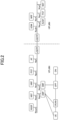
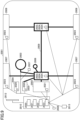
- Fig. 1 is a drawing illustrating an example of a communication system.
- the communication system includes a UE that is a terminal 20, and a plurality of network nodes 30.
- one network node 30 corresponds to each function, but multiple functions may be implemented by one network node 30 or one function may be implemented by multiple network nodes 30.
- the "connections" described below may be either a logical connection or a physical connection.
- RAN Radio Access Network
- AMF Access and Mobility Management Function
- UPF User plane function
- the AMF is a network node 30 having functions of, for example, terminating the RAN interface, terminating the NAS (Non-Access Stratum), managing registration, managing connection, managing reachability, and managing mobility.
- the UPF is a network node 30 interconnected with DN (Data Network), and has functions such as a PDU (Protocol Data Unit) session point to an external unit, routing and forwarding packets, and QoS (Quality of Service) handling of the user plane.
- DN Data Network
- PDU Protocol Data Unit
- QoS Quality of Service
- AMF is connected to UE, RAN, SMF (Session Management Function), NSSF (Network Slice Selection Function), NEF (Network Exposure Function), NRF (Network Repository Function), UDM (Unified Data Management), AUSF (Authentication Server Function), PCF (Policy Control Function), and AF (Application Function).
- AMF, SMF, NSSF, NEF, NRF, UDM, AUSF, PCF, and AF are network nodes 30 connected to each other via interfaces Namf, Nsmf, Nnssf, Nnef, Nnrf, Nudm, Nausf, Npcf, Naf based on the respective services.
- the SMF is a network node 30 having functions such as session management, Internet Protocol (IP) address assignment and management of UE, DHCP (Dynamic Host Configuration Protocol) function, ARP (Address Resolution Protocol) proxy, and roaming function.
- the NEF is a network node 30 having a function of indicating capabilities and events to other NFs (Network Functions).
- the NSSF is a network node 30 having functions of, for example, selecting the network slice to which the UE is to be connected, determining the allowed NSSAI (Network Slice Selection Assistance Information), determining the configured NSSAI, and determining the AMF set to which the UE is to be connected.
- PCF is a network node 30 having a function of performing policy control of the network.
- AF is a network node 30 having a function of controlling an application server.
- NRF is a network node 30 having a function of discovering NF instances which provide services.
- UDM is a network node 30 that manages subscriber data and authentication data. UDM is connected to UDR (User Data Repository) that stores the above-described data;
- Fig. 2 is a drawing illustrating an example of a communication system under a roaming environment.
- the network includes a UE that is a terminal 20, and a plurality of network nodes 30.
- one network node 30 corresponds to each function, but multiple functions may be implemented by one network node 30 or one function may be implemented by multiple network nodes 30.
- the "connections" described below may be either a logical connection or a physical connection.
- RAN is a network node 30 having a wireless access function, and is connected to UE, AMF and UPF.
- AMF is a network node 30 having functions of, for example, terminating the RAN interface, terminating NAS, managing registration, managing connection, managing reachability, and managing mobility.
- UPF is a network node 30 having functions of, for example, PDU session point to an external unit mutually connected to DN, routing and forwarding of packets, and QoS handling of the user plane.
- UPF and DN are included in a network slice. In a wireless communication network in an embodiment of the present invention, multiple network slices are included.
- AMF is connected to UE, RAN, SMF, NSSF, NEF, NRF, UDM, AUSF, PCF, AF, and SEPP (Security Edge Protection Proxy).
- AMF, SMF, NSSF, NEF, NRF, UDM, AUSF, PCF, and AF are network nodes 30 connected to each other via interfaces Namf, Nsmf, Nnssf, Nnef, Nnrf, Nudm, Nausf, Npcf, Naf based on the respective services.
- SMF is a network node 30 having functions such as session management, IP address assignment and management of UE, a DHCP function, an ARP proxy, and a roaming function.
- NEF is a network node 30 having a function of indicating capabilities and events to other NFs.
- NSSF is a network node 30 having functions of, for example, selecting the network slice to which the UE is to be connected, determining NSSAI to be allowed, determining NSSAI to be configured, and determining AMF set to which the UE is to be connected.
- PCF is a network node 30 having a function of performing policy control of the network.
- AF is a network node 30 having a function of controlling an application server.
- NRF is a network node 30 having a function of discovering NF instances which provide services.
- SEPP is a non-transparent proxy and filters control plane messages between PLMNs (Public Land Mobile Networks).
- vSEPP shown in Fig. 2 is a SEPP in a visited network, and hSEPP is a SEPP in a home network.
- the UE is in a roaming environment connected to RAN and AMF in VPLMN (Visited PLMN).
- VPLMN and HPLMN are connected via vSEPP and hSEPP.
- the UE can communicate with the UDM of HPLMN via, for example, the AMF of VPLMN.
- a subscriber uses a resource in the network.
- the resource is, for example, a QoS (Quality of Service) flow, a computing resource, or the like.
- QoS Quality of Service
- the PCF performs policy determination. For example, in the GBR (Guaranteed Bit Rate) - QoS flow, even if the NG-RAN or NWDAF (Network data analytics function) indicates, to the PCF, that the QoS is jeopardized, the PCF is only capable of lowering the QoS level by using the alternative QoS mechanism, and thus, is incapable of guaranteeing the QoS. In addition, with respect to the computing resource, the PCF is expected to be incapable of guaranteeing the container capability capacity in the same manner as in a case of the QoS flow.
- the allocated resource is jeopardized in accordance with the resource movement accompanied by the terminal movement, for example.
- something is jeopardized may mean that a target is jeopardized due to an occurrence of an event or a situation change.
- a resource is jeopardized may mean a state in which there is a risk that the resource cannot be guaranteed, maintained, or ensured, and may mean a state in which there is a risk that the QoS cannot be guaranteed, for example.
- the PCF performs policy determination.
- the PCF performs smoothing of the resource use among the subscribers.
- the PCF cannot cope with a case in which the entire resource of the subscriber group is exhausted.
- a function of providing LCM (Life Cycle Management) services, an interface, and the like are defined in the OAM (Operations, Administration and Maintenance) domain.
- Os-Ma-nfvo and Ve-Vnfm-em are defined as interfaces (refer to non-patent document 3)
- NFVO Network Functions Virtualization Orchestration
- VNFM Virtual Network Function Manager
- these interfaces and functions are not capable of performing a resource control with a granularity that can sufficiently support the resource allocation to a subscriber or a subscriber group.
- a new MsNF Management service Network Function or Management service NF
- MsNF Management service Network Function
- cloud technologies for example, CPU, I/O band, or the like
- the new MsNF provides LCM services with a resource granularity to be applied to a subscriber or a subscriber group (for example, QoS flow granularity, QoS flow group granularity, container capability capacity granularity, or the like).
- a resource granularity for example, QoS flow granularity, QoS flow group granularity, container capability capacity granularity, or the like.
- the name of MsNF is just an example, and may be a different name.
- the MsNF may be located in the OAM domain.
- the PCF performs guaranteeing of the resource allocation (for example, guaranteeing of QoS, guaranteeing of flock QoS, guaranteeing of container capability capacity, or the like) by cooperating with the MsNF.
- the MsNF can enhance the cooperation between the network C-plane and OAM by using cloud technologies.
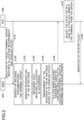
- Fig. 3 is a sequence diagram for describing an example (1) of guaranteeing of the resource allocation in an embodiment of the present invention.
- the PCF 30B indicates a target terminal or target terminal group, resource allocation requirements, and a handling policy to the MsNF 30A.
- the MsNF 30A identifies an NF instance that accommodates the terminal or the terminal group.
- the MsNF 30A monitors the resource use by the NF instance.
- the MsNF 30A recognizes that the resource allocation is jeopardized.
- the MsNF 30A enhances the resource of the NF instance based on the indicated handling policy. It is to be noted that, in step S105, the MsNF 30A may allocate a resource allocated to a terminal to another terminal depending on the handling policy.
- the MsNF 30A indicates, to the PCF 30B, information indicating that the resource of the NF instance cannot be enhanced and the reason thereof.
- the PCF 30B may adjust the handling policy or may remove the target terminal from the group in a case of flock QoS.
- the PCF 30B indicates the updated handling policy to the MsNF 30A.
- Fig. 4 is a sequence diagram for describing an example (2) of guaranteeing of the resource allocation in an embodiment of the present invention.
- the PCF 30B indicates a target terminal or target terminal group, resource allocation requirements, and a handling policy to the MsNF 30A.
- the MsNF 30A identifies an NF instance that accommodates the terminal or the terminal group.
- the MsNF 30A indicates, to the MDA 30C, that the MsNF 30A subscribes to the MDA (Management Data Analytics) analysis related to the resource use by the NF instance (refer to non-patent document 5).
- the MsNF 30A receives an indication indicating that the resource allocation is jeopardized from the MDA 30C.
- the MsNF 30A enhances the resource of the NF instance based on the handling policy. It is to be noted that, in step S205, the MsNF 30A may allocate a resource allocated to a terminal to another terminal depending on the handling policy.
- the MsNF 30A indicates, to the PCF 30B, information indicating that the resource of the NF instance cannot be enhanced and the reason thereof.
- the PCF 30B may adjust the handling policy or may remove the target terminal from the group in a case of flock QoS.
- the PCF 30B indicates the updated handling policy to the MsNF 30A.
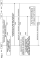
- Fig. 5 is a sequence diagram for describing an example (3) of guaranteeing of the resource allocation in an embodiment of the present invention.
- the PCF 30B transmits an indication related to the resource use by a terminal or a terminal group to at least one of the NG-RAN 30C, UCRF 30D, or NWDAF 30E.
- the UCRF User Computing Resource Function
- the PCF 30B may indicate, to the NWDAF 30E, that the PCF 30B subscribes to the analysis related to the resource use by a terminal or a terminal group.
- step S302 the PCF 30B receives an indication indicating that the resource allocation is jeopardized from at least one of the NG-RAN 30C, UCRF 30D, or NWDAF 30E.
- the PCF 30B determines that the resource allocation is jeopardized.
- the PCF 30B identifies an NF instance that accommodates the affected terminal or terminal group.
- the PCF 30B indicates the affected terminal or terminal group, the NF instance, and the resource allocation requirements.
- the MsNF 30A enhances the resource of the NF instance based on the indicated resource allocation requirements.
- the MsNF 30A transmits a response to the PCF 30B.
- the detection of the resources allocated to a terminal or a terminal group being jeopardized can be performed, the enhancement of the resources of the NF instance that accommodates the terminal or terminal group can be performed, and the guaranteeing of the resources allocated to the terminal or the terminal group can be performed.
- the resources on the network used by a subscriber can be guaranteed.
- the base station 10, the network node 30 and the terminal 20 include functions for implementing the embodiments described above. It should be noted, however, that each of the base station 10, the network node 30 and the terminal 20 may include only some of the functions in the embodiments.
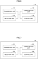
- Fig. 6 is a diagram illustrating an example of a functional configuration of the base station 10.
- the base station 10 includes a transmission unit 110, a reception unit 120, a configuration unit 130, and a control unit 140.
- the functional configuration illustrated in Fig. 6 is merely an example. Functional divisions and names of functional units may be anything as long as operations according to an embodiment of the present invention can be performed.
- the network node 30 may have the same functional configuration as the base station 10.
- the network nodes 30 having multiple different functions in the system architecture may be composed of multiple network nodes 30 separated for each function.
- the transmission unit 110 includes a function for generating a signal to be transmitted to the terminal 20 or to another network node 30 and transmitting the signal in a wired manner or wireless manner.
- the reception unit 120 includes a function for receiving various signals transmitted from the terminal 20 or another network node 30, and for acquiring, for example, information of an upper layer from the received signals.
- the configuration unit 130 stores preset configuration information and various configuration information items to be transmitted to the terminal 20 in a storage apparatus and reads the preset configuration information from the storage apparatus as necessary.
- Contents of the configuration information are, for example, configurations related to the resource allocation.
- the control unit 140 performs a process related to a network slice in the network as described in the embodiments. Further, the control unit 140 performs a process related to communications with the terminal 20.
- the functional units related to signal transmission in the control unit 140 may be included in the transmission unit 110, and the functional units related to signal reception in the control unit 140 may be included in the reception unit 120.
- Fig. 7 is a diagram illustrating an example of a functional configuration of the terminal 20.
- the terminal 20 includes a transmission unit 210, a reception unit 220, a configuration unit 230, and a control unit 240.
- the functional configuration illustrated in Fig. 7 is merely an example. Functional divisions and names of functional units may be anything as long as operations according to an embodiment of the present invention can be performed.
- the transmission unit 210 generates a transmission signal from transmission data and transmits the transmission signal wirelessly.
- the reception unit 220 receives various signals wirelessly and obtains upper layer signals from the received physical layer signals. Further, the reception unit 220 has a function of receiving NR-PSS, NR-SSS, NR-PBCH, DL/UL control signals, or reference signals transmitted from the network node 30.
- the configuration unit 230 stores various types of configuration information received from the network node 30 by the reception unit 220 in the storage device and reads the configuration information from the storage device as necessary. In addition, the configuration unit 230 also stores pre-configured configuration information. Contents of the configuration information are, for example, configurations related to the resource allocation.
- the control unit 240 performs a process related to the connection control to the network and the network slice as described in the embodiments.
- the functional units related to signal transmission in the control unit 240 may be included in the transmission unit 210, and the functional units related to signal reception in the control unit 240 may be included in the reception unit 220.
- each functional block is realized by a freely-selected combination of hardware and/or software. Further, realizing means of each functional block is not limited in particular. In other words, each functional block may be realized by a single apparatus in which multiple elements are coupled physically and/or logically, or may be realized by two or more apparatuses that are physically and/or logically separated and are physically and/or logically connected (e.g., wired and/or wireless).
- the functional blocks may be realized by combining the above-described one or more apparatuses with software.
- Functions include, but are not limited to, judging, determining, calculating, processing, deriving, investigating, searching, checking, receiving, transmitting, outputting, accessing, resolving, selecting, establishing, comparing, assuming, expecting, and deeming; broadcasting, notifying, communicating, forwarding, configuring, reconfiguring, allocating, mapping, and assigning, etc.
- a functional block (component) that functions to transmit is called a transmitting unit or a transmitter. In either case, as described above, the implementation method is not particularly limited.
- the network node 30, terminal 20, etc. may function as a computer for processing the radio communication method of the present disclosure.
- Fig. 8 is a drawing illustrating an example of hardware structures of the base station 10 and the terminal 20 according to an embodiment of the present invention.
- the network node 30 may have the same hardware configuration as the base station 10.
- Each of the above-described base station 10 and the terminal 20 may be physically a computer device including a processor 1001, a storage device 1002, an auxiliary storage device 1003, a communication device 1004, an input device 1005, an output device 1006, a bus 1007, etc.
- the term “device” can be read as a circuit, a device, a unit, etc.
- the hardware structures of the base station 10 and the terminal 20 may include one or more of each of the devices illustrated in the figure, or may be configured without including some of the devices.
- Each function in the base station 10 and the terminal 20 is realized by having the processor 1001 perform an operation by reading predetermined software (programs) onto hardware such as the processor 1001 and the storage device 1002, and by controlling communication by the communication device 1004 and controlling at least one of reading or writing of data in the storage device 1002 and the auxiliary storage device 1003.
- the processor 1001 controls the entire computer by, for example, controlling the operating system.
- the processor 1001 may include a central processing unit (CPU) including an interface with a peripheral apparatus, a control apparatus, a calculation apparatus, a register, etc.
- CPU central processing unit
- control unit 140, control unit 240, and the like may be implemented by the processor 1001.
- the processor 1001 reads out onto the storage device 1002 a program (program code), a software module, or data from the auxiliary storage device 1003 and/or the communication device 1004, and performs various processes according to the program, the software module, or the data.
- a program is used that causes the computer to perform at least a part of operations according to an embodiment of the present invention described above.
- the control unit 140 of the base station 10 illustrated in Fig. 6 may be realized by control programs that are stored in the storage device 1002 and are executed by the processor 1001.
- the control unit 240 of the terminal 20 illustrated in Fig. 7 may be realized by control programs that are stored in the storage device 1002 and are executed by the processor 1001.
- the various processes have been described to be performed by a single processor 1001. However, the processes may be performed by two or more processors 1001 simultaneously or sequentially.
- the processor 1001 may be implemented by one or more chips. It should be noted that the program may be transmitted from a network via a telecommunication line.
- the storage device 1002 is a computer-readable recording medium, and may include at least one of a ROM (Read Only Memory), an EPROM (Erasable Programmable ROM), an EEPROM (Electrically Erasable Programmable ROM), a RAM (Random Access Memory), etc.
- the storage device 1002 may be referred to as a register, a cache, a main memory, etc.
- the storage device 1002 is capable of storing programs (program codes), software modules, or the like, that are executable for performing communication processes according to an embodiment of the present invention.
- the auxiliary storage device 1003 is a computer-readable recording medium, and may include at least one of, for example, an optical disk such as a CD-ROM (Compact Disc ROM), a hard disk drive, a flexible disk, a magneto optical disk (e.g., compact disc, digital versatile disc, Blu-ray (registered trademark) disk), a smart card, a flash memory (e.g., card, stick, key drive), a floppy (registered trademark) disk, a magnetic strip, etc.
- the above recording medium may be a database including the storage device 1002 and/or the auxiliary storage device 1003, a server, or any other appropriate medium.
- the communication device 1004 is hardware (transmission or reception device) for communicating with computers via at least one of a wired network or a wireless network, and may be referred to as a network device, a network controller, a network card, a communication module, etc.
- the communication device 1004 may comprise a high frequency switch, duplexer, filter, frequency synthesizer, or the like, for example, to implement at least one of a frequency division duplex (FDD) or a time division duplex (TDD).
- FDD frequency division duplex
- TDD time division duplex
- the transmitting/receiving antenna, the amplifier unit, the transmitting/receiving unit, the transmission line interface, and the like may be implemented by the communication device 1004.
- the transmitting/receiving unit may be physically or logically divided into a transmitting unit and a receiving unit.
- the input device 1005 is an input device that receives an external input (e.g., keyboard, mouse, microphone, switch, button, sensor).
- the output device 1006 is an output device that outputs something to the outside (e.g., display, speaker, LED lamp). It should be noted that the input device 1005 and the output device 1006 may be integrated into a single device (e.g., touch panel).
- the apparatuses including the processor 1001, the storage device 1002, etc. are connected to each other via the bus 1007 used for communicating information.
- the bus 1007 may include a single bus, or may include different buses between the apparatuses.
- each of the base station 10 and terminal 20 may include hardware such as a microprocessor, a digital signal processor (DSP), an ASIC (Application Specific Integrated Circuit), a PLD (Programmable Logic Device), a FPGA (Field Programmable Gate Array), etc., and a part or all of each functional block may be realized by the hardware.
- the processor 1001 may be implemented by at least one of the above hardware elements.
- Fig. 9 shows an example of a configuration of a vehicle 2001.
- the vehicle 2001 includes a drive unit 2002, a steering unit 2003, an accelerator pedal 2004, a brake pedal 2005, a shift lever 2006, a front wheel 2007, a rear wheel 2008, an axle 2009, an electronic control unit 2010, various sensors 2021-2029, an information service unit 2012, and a communication module 2013.
- the aspects/embodiments described in the present disclosure may be applied to a communication device mounted in the vehicle 2001, and may be applied to, for example, the communication module 2013.
- the drive unit 2002 may include, for example, an engine, a motor, and a hybrid of an engine and a motor.
- the steering unit 2003 includes at least a steering wheel and is configured to steer at least one of the front wheel or the rear wheel, based on the operation of the steering wheel operated by the user.
- the electronic control unit 2010 includes a microprocessor 2031, a memory (ROM, RAM) 2032, and a communication port (IO port) 2033.
- the electronic control unit 2010 receives signals from the various sensors 2021-2029 provided in the vehicle 2001.
- the electronic control unit 2010 may be referred to as an ECU (Electronic control unit).
- the signals from the various sensors 2021 to 2029 include a current signal from a current sensor 2021 which senses the current of the motor, a front or rear wheel rotation signal acquired by a revolution sensor 2022, a front or rear wheel pneumatic signal acquired by a pneumatic sensor 2023, a vehicle speed signal acquired by a vehicle speed sensor 2024, an acceleration signal acquired by an acceleration sensor 2025, a stepped-on accelerator pedal signal acquired by an accelerator pedal sensor 2029, a stepped-on brake pedal signal acquired by a brake pedal sensor 2026, an operation signal of a shift lever acquired by a shift lever sensor 2027, and a detection signal, acquired by an object detection sensor 2028, for detecting an obstacle, a vehicle, a pedestrian, and the like.
- the information service unit 2012 includes various devices for providing various kinds of information such as driving information, traffic information, and entertainment information, including a car navigation system, an audio system, a speaker, a television, and a radio, and one or more ECUs controlling these devices.
- the information service unit 2012 provides various types of multimedia information and multimedia services to the occupants of the vehicle 2001 by using information obtained from the external device through the communication module 2013 or the like.
- a driving support system unit 2030 includes: various devices for providing functions of preventing accidents and reducing driver's operating loads such as a millimeter wave radar, a LiDAR (Light Detection and Ranging), a camera, a positioning locator (e.g., GNSS, etc.), map information (e.g., high definition (HD) map, autonomous vehicle (AV) map, etc.), a gyro system (e.g., IMU (Inertial Measurement Unit), INS (Inertial Navigation System), etc.), an AI (Artificial Intelligence) chip, an AI processor; and one or more ECUs controlling these devices.
- the driving support system unit 2030 transmits and receives various types of information via the communication module 2013 to realize a driving support function or an autonomous driving function.
- the communication module 2013 may communicate with the microprocessor 2031 and components of the vehicle 2001 via a communication port.
- the communication module 2013 transmits and receives data via a communication port 2033, to and from the drive unit 2002, the steering unit 2003, the accelerator pedal 2004, the brake pedal 2005, the shift lever 2006, the front wheel 2007, the rear wheel 2008, the axle 2009, the microprocessor 2031 and the memory (ROM, RAM) 2032 in the electronic control unit 2010, and sensors 2021 to 2029 provided in the vehicle 2001.
- the communication module 2013 is a communication device that can be controlled by the microprocessor 2031 of the electronic control unit 2010 and that is capable of communicating with external devices. For example, various kinds of information are transmitted to and received from external devices through radio communication.
- the communication module 2013 may be internal to or external to the electronic control unit 2010.
- the external devices may include, for example, a base station, a mobile station, or the like.
- the communication module 2013 transmits a current signal, which is input to the electronic control unit 2010 from the current sensor, to the external devices through radio communication.
- the communication module 2013 also transmits, to the external devices through radio communication, the front or rear wheel rotation signal acquired by the revolution sensor 2022, the front or rear wheel pneumatic signal acquired by the pneumatic sensor 2023, the vehicle speed signal acquired by the vehicle speed sensor 2024, the acceleration signal acquired by the acceleration sensor 2025, the stepped-on accelerator pedal signal acquired by the accelerator pedal sensor 2029, the stepped-on brake pedal signal acquired by the brake pedal sensor 2026, the operation signal of the shift lever acquired by the shift lever sensor 2027, and the detection signal, acquired by the object detection sensor 2028, for detecting an obstacle, a vehicle, a pedestrian, and the like, that are input to the electronic control unit 2010.
- the communication module 2013 receives various types of information (traffic information, signal information, inter-vehicle information, etc.) transmitted from the external devices and displays the received information on the information service unit 2012 provided in the vehicle 2001.
- the communication module 2013 stores the various types of information received from the external devices in the memory 2032 available to the microprocessor 2031.
- the microprocessor 2031 may control the drive unit 2002, the steering unit 2003, the accelerator pedal 2004, the brake pedal 2005, the shift lever 2006, the front wheel 2007, the rear wheel 2008, the axle 2009, the sensors 2021-2029, etc., mounted in the vehicle 2001.
- a network node includes: a reception unit configured to receive, from a first network node, information indicating a terminal or a terminal group that is a target of guaranteeing of resource allocation, requirements of the resource allocation, and a handling policy; and a control unit configured to identify an NF (Network Function) instance that accommodates the terminal or the terminal group.
- the control unit performs enhancement of a resource of the NF instance based on the handling policy in a case where a state is recognized in which there is a risk that the resource allocation cannot be guaranteed.
- the detection of the resources allocated to a terminal or a terminal group being jeopardized can be performed, the enhancement of the resources of the NF instance that accommodates the terminal or terminal group can be performed, and the guaranteeing of the resources allocated to the terminal or the terminal group can be performed.
- the resources on the network used by a subscriber can be guaranteed.
- the control unit may monitor a resource use by the NF instance and may recognize a state in which there is a risk that the resource allocation cannot be guaranteed. According to the above-described configuration, the detection of the resources allocated to a terminal or a terminal group being jeopardized can be performed, the enhancement of the resources of the NF instance that accommodates the terminal or terminal group can be performed, and the guaranteeing of the resources allocated to the terminal or the terminal group can be performed.
- the reception unit may receive an analysis related to the resource use by the NF instance from a second network node, and the control unit may recognize a state in which there is a risk that the resource allocation cannot be guaranteed. According to the above-described configuration, the detection of the resources allocated to a terminal or a terminal group being jeopardized can be performed, the enhancement of the resources of the NF instance that accommodates the terminal or terminal group can be performed, and the guaranteeing of the resources allocated to the terminal or the terminal group can be performed.
- the network node may further include a transmission unit configured to transmit information indicating that the enhancement of the resource of the NF instance cannot be performed and a reason why the enhancement of the resource of the NF instance cannot be performed to the first network node in a case where the enhancement of the resource of the NF instance cannot be performed by the control unit.
- a transmission unit configured to transmit information indicating that the enhancement of the resource of the NF instance cannot be performed and a reason why the enhancement of the resource of the NF instance cannot be performed to the first network node in a case where the enhancement of the resource of the NF instance cannot be performed by the control unit.
- the reception unit may receive an updated handling policy from the first network node after the information indicating that the enhancement of the resource of the NF instance cannot be performed and the reason why the enhancement of the resource of the NF instance cannot be performed are transmitted by the transmission unit to the first network node.
- a network node includes: a transmission unit configured to transmit an indication related to resource allocation of a terminal or a terminal group to a first network node; a reception unit configured to receive information indicating a state in which there is a risk that the resource allocation cannot be guaranteed from the first network node; and a control unit configured to identify an NF (Network Function) instance that accommodates the terminal or the terminal group.
- the transmission unit transmits information indicating the terminal or the terminal group, the NF instance, and requirements of the resource allocation to a second network node.
- the detection of the resources allocated to a terminal or a terminal group being jeopardized can be performed, the enhancement of the resources of the NF instance that accommodates the terminal or terminal group can be performed, and the guaranteeing of the resources allocated to the terminal or the terminal group can be performed.
- the resources on the network used by a subscriber can be guaranteed.
- the software executed by a processor included in the network node 30 according to an embodiment of the present invention and the software executed by a processor included in the terminal 20 according to an embodiment of the present invention may be stored in a random access memory (RAM), a flash memory, a read only memory (ROM), an EPROM, an EEPROM, a register, a hard disk (HDD), a removable disk, a CD-ROM, a database, a server, or any other appropriate recording medium.
- RAM random access memory
- ROM read only memory
- EPROM an EPROM
- EEPROM electrically erasable programmable read-only memory
- register a register
- HDD hard disk
- CD-ROM compact disc-read only memory
- database a database
- server or any other appropriate recording medium.
- information indication may be performed not only by methods described in an aspect/embodiment of the present specification but also a method other than those described in an aspect/embodiment of the present specification.
- the information transmission may be performed by physical layer signaling (e.g., DCI (Downlink Control Information), UCI (Uplink Control Information)), upper layer signaling (e.g., RRC (Radio Resource Control) signaling, MAC (Medium Access Control) signaling, broadcast information (MIB (Master Information Block), SIB (System Information Block))), other signals, or combinations thereof.
- RRC signaling may be referred to as an RRC message.
- the RRC signaling may be, for example, an RRC connection setup message, an RRC connection reconfiguration message, or the like.
- Each aspect/embodiment described in the present disclosure may be applied to at least one of a system using LTE (Long Term Evolution), LTE-A (LTE-Advanced), SUPER 3G, IMT-Advanced, 4G (4th generation mobile communication system), 5G (5th generation mobile communication system), FRA (Future Radio Access), NR (new Radio), W-CDMA (registered trademark), GSM (registered trademark), CDMA2000, UMB (Ultra Mobile Broadband), IEEE 802.11 (Wi-Fi (registered trademark)), IEEE 802.16 (WiMAX (registered trademark)), IEEE 802.20, UWB (Ultra-WideBand), Bluetooth (registered trademark), and other appropriate systems, and a next generation system enhanced therefrom. Further, multiple systems may also be applied in combination (e.g., at least one of LTE or LTE-A combined with 5G, etc.).
- Each aspect/embodiment described in the present disclosure may be applied to at least one of a system using LTE (Long Term Evolution), LTE-A (LTE-Advanced), SUPER 3G, IMT-Advanced, 4G (4th generation mobile communication system), 5G (5th generation mobile communication system), 6th generation mobile communication system (6G), xth generation mobile communication system (xG) (xG (x is, for example, an integer or a decimal)), FRA (Future Radio Access), NR (new Radio), New radio access (NX), Future generation radio access (FX), W-CDMA (registered trademark), GSM (registered trademark), CDMA2000, UMB (Ultra Mobile Broadband), IEEE 802.11 (Wi-Fi (registered trademark)), IEEE 802.16 (WiMAX (registered trademark)), IEEE 802.20, UWB (Ultra-WideBand), Bluetooth (registered trademark), and other appropriate systems, and a next generation system enhanced, modified, developed, or defined therefrom
- the particular operations, that are supposed to be performed by the network node 30 in the present specification, may be performed by an upper node in some cases.
- various operations performed for communicating with the terminal 20 may be performed by at least one of the network node 30 and another network node other than the network node 30 (for example, but not limited to, MME or S-GW).
- MME Mobility Management Entity
- S-GW Serving GPRS Support Node
- the information or signals described in this disclosure may be output from a higher layer (or lower layer) to a lower layer (or higher layer).
- the information or signals may be input or output through multiple network nodes.
- the input or output information may be stored in a specific location (e.g., memory) or managed using management tables.
- the input or output information may be overwritten, updated, or added.
- the information that has been output may be deleted.
- the information that has been input may be transmitted to another apparatus.
- a decision or a determination in an embodiment of the present invention may be realized by a value (0 or 1) represented by one bit, by a boolean value (true or false), or by comparison of numerical values (e.g., comparison with a predetermined value).
- Software should be broadly interpreted to mean, whether referred to as software, firmware, middle-ware, microcode, hardware description language, or any other name, instructions, instruction sets, codes, code segments, program codes, programs, subprograms, software modules, applications, software applications, software packages, routines, subroutines, objects, executable files, executable threads, procedures, functions, and the like.
- software, instructions, information, and the like may be transmitted and received via a transmission medium.
- a transmission medium for example, in the case where software is transmitted from a website, server, or other remote source using at least one of wired line technologies (such as coaxial cable, fiber optic cable, twisted pair, digital subscriber line (DSL), etc.) or wireless technologies (infrared, microwave, etc.), at least one of these wired line technologies or wireless technologies is included within the definition of the transmission medium.
- wired line technologies such as coaxial cable, fiber optic cable, twisted pair, digital subscriber line (DSL), etc.
- wireless technologies infrared, microwave, etc.
- Information, a signal, or the like, described in the present specification may be represented by using any one of various different technologies.
- data, an instruction, a command, information, a signal, a bit, a symbol, a chip, or the like, described throughout the present application may be represented by a voltage, an electric current, electromagnetic waves, magnetic fields, a magnetic particle, optical fields, a photon, or a combination thereof.
- a channel and/or a symbol may be a signal (signaling).
- a signal may be a message.
- the component carrier CC may be referred to as a carrier frequency, cell, frequency carrier, or the like.
- system and “network” are used interchangeably.
- a radio resource may be what is indicated by an index.
- BS Base Station
- Radio Base Station Base Station
- Base Station Apparatus Fixed Station
- NodeB NodeB
- eNodeB eNodeB
- gNodeB gNB
- Access Point "Transmission Point”
- Reception Point Transmission/Reception Point
- Cell Cell
- Sector Cell Group
- Carrier Carrier
- Component Carrier and the like
- the base station may be referred to as a macro-cell, a small cell, a femtocell, a picocell and the like.
- the base station may accommodate (provide) one or more (e.g., three) cells.
- the entire coverage area of the base station may be divided into a plurality of smaller areas, and each smaller area may provide communication services by means of a base station subsystem (e.g., an indoor small base station or a remote Radio Head (RRH)).
- a base station subsystem e.g., an indoor small base station or a remote Radio Head (RRH)
- RRH remote Radio Head
- the term "cell” or “sector” refers to a part or all of the coverage area of at least one of the base station and base station subsystem that provides communication services at the coverage.
- MS mobile station
- UE user equipment
- terminal terminal
- the mobile station may be referred to, by a person skilled in the art, as a subscriber station, a mobile unit, a subscriber unit, a wireless unit, a remote unit, a mobile device, a wireless device, a wireless communication device, a remote device, a mobile subscriber station, an access terminal, a mobile terminal, a wireless terminal, a remote terminal, a handset, a user agent, a mobile client, a client, or some other appropriate terms.
- At least one of the base station or the mobile station may be referred to as a transmission apparatus, reception apparatus, communication apparatus, or the like.
- the at least one of the base station or the mobile station may be a device mounted on the mobile station, the mobile station itself, or the like.
- the mobile station may be a vehicle (e.g., a car, an airplane, etc.), an unmanned mobile body (e.g., a drone, an automated vehicle, etc.), or a robot (manned or unmanned).
- At least one of the base station or the mobile station may include an apparatus that does not necessarily move during communication operations.
- at least one of the base station and the mobile station may be an IoT (Internet of Things) device such as a sensor.
- IoT Internet of Things
- the base station in the present disclosure may be read as the user terminal.
- each aspect/embodiment of the present disclosure may be applied to a configuration in which communications between the base station and the user terminal are replaced by communications between multiple terminals 20 (e.g., may be referred to as D2D (Device-to-Device), V2X (Vehicle-to-Everything), etc.).
- a function of the network node 30 described above may be provided by the terminal 20.
- the phrases "up” and “down” may also be replaced by the phrases corresponding to terminal-to-terminal communication (e.g., "side").
- an uplink channel, a downlink channel, or the like may be read as a sidelink channel.
- the user terminal in the present disclosure may be read as the base station.
- the function of the user terminal described above may be provided by the base station.
- the term "determining” used in the present specification may include various actions or operations.
- the terms “determination” and “decision” may include “determination” and “decision” made with judging, calculating, computing, processing, deriving, investigating, searching (looking up, search, inquiry) (e.g., search in a table, a database, or another data structure), or ascertaining.
- the "determining” may include “determining” made with receiving (e.g., receiving information), transmitting (e.g., transmitting information), inputting, outputting, or accessing (e.g., accessing data in a memory).
- the "determining” may include a case in which “resolving”, “selecting”, “choosing”, “establishing”, “comparing”, or the like is deemed as “determining”.
- the “determining” may include a case in which a certain action or operation is deemed as “determining”.
- “decision” may be read as “assuming", “expecting”, or “considering”, etc.
- connection means any direct or indirect connection or connection between two or more elements and may include the presence of one or more intermediate elements between the two elements “connected” or “coupled” with each other.
- the coupling or connection between the elements may be physical, logical, or a combination thereof.
- connection may be read as "access”.
- the two elements may be thought of as being “connected” or “coupled” to each other using at least one of the one or more wires, cables, or printed electrical connections and, as a number of non-limiting and non-inclusive examples, electromagnetic energy having wavelengths in the radio frequency region, the microwave region, and the light (both visible and invisible) region.
- the reference signal may be abbreviated as RS or may be referred to as a pilot, depending on the applied standards.
- references to an element using terms such as "first” or “second” as used in the present disclosure does not generally limit the amount or the order of those elements. These terms may be used in the present disclosure as a convenient way to distinguish between two or more elements. Therefore, references to the first and second elements do not imply that only two elements may be employed or that the first element must in some way precede the second element.
- the term "A and B are different” may mean “A and B are different from each other.” It should be noted that the term “A and B are different” may mean “A and B are different from C.” Terms such as “separated” or “combined” may be interpreted in the same way as the above-described "different”.
- notification (transmission/reporting) of predetermined information is not limited to an explicit notification (transmission/reporting), and may be performed by an implicit notification (transmission/reporting) (e.g., by not performing notification (transmission/reporting) of the predetermined information).
Landscapes
- Engineering & Computer Science (AREA)
- Computer Networks & Wireless Communication (AREA)
- Signal Processing (AREA)
- Mobile Radio Communication Systems (AREA)
Applications Claiming Priority (1)
| Application Number | Priority Date | Filing Date | Title |
|---|---|---|---|
| PCT/JP2021/047149 WO2023119386A1 (ja) | 2021-12-20 | 2021-12-20 | ネットワークノード |
Publications (2)
| Publication Number | Publication Date |
|---|---|
| EP4456593A1 true EP4456593A1 (de) | 2024-10-30 |
| EP4456593A4 EP4456593A4 (de) | 2025-10-22 |
Family
ID=86901546
Family Applications (1)
| Application Number | Title | Priority Date | Filing Date |
|---|---|---|---|
| EP21968823.1A Pending EP4456593A4 (de) | 2021-12-20 | 2021-12-20 | Netzwerkknoten |
Country Status (2)
| Country | Link |
|---|---|
| EP (1) | EP4456593A4 (de) |
| WO (1) | WO2023119386A1 (de) |
Cited By (1)
| Publication number | Priority date | Publication date | Assignee | Title |
|---|---|---|---|---|
| EP4503541A4 (de) * | 2022-03-25 | 2026-01-07 | Ntt Docomo Inc | Netzwerkknoten und kommunikationsverfahren |
Family Cites Families (1)
| Publication number | Priority date | Publication date | Assignee | Title |
|---|---|---|---|---|
| JP7287470B2 (ja) * | 2019-01-09 | 2023-06-06 | 日本電気株式会社 | アクセスネットワークノード |
-
2021
- 2021-12-20 WO PCT/JP2021/047149 patent/WO2023119386A1/ja not_active Ceased
- 2021-12-20 EP EP21968823.1A patent/EP4456593A4/de active Pending
Cited By (1)
| Publication number | Priority date | Publication date | Assignee | Title |
|---|---|---|---|---|
| EP4503541A4 (de) * | 2022-03-25 | 2026-01-07 | Ntt Docomo Inc | Netzwerkknoten und kommunikationsverfahren |
Also Published As
| Publication number | Publication date |
|---|---|
| WO2023119386A1 (ja) | 2023-06-29 |
| EP4456593A4 (de) | 2025-10-22 |
Similar Documents
| Publication | Publication Date | Title |
|---|---|---|
| EP4456593A1 (de) | Netzwerkknoten | |
| EP4422346A1 (de) | Netzwerkknoten und kommunikationsverfahren | |
| EP4694540A1 (de) | Netzwerkknoten, endgerät und steuerungsverfahren | |
| EP4507447A1 (de) | Netzwerkknoten und kommunikationsverfahren | |
| EP4642078A1 (de) | Netzwerkknoten und kommunikationsverfahren | |
| EP4668716A1 (de) | Netzwerkknoten und endgerät | |
| EP4668953A1 (de) | Netzwerkknoten und kommunikationsverfahren | |
| EP4668717A1 (de) | Netzwerkknoten und kommunikationsverfahren | |
| EP4472285A1 (de) | Netzwerkknoten und kommunikationsverfahren | |
| EP4550925A1 (de) | Netzwerkknoten, basisstation und kommunikationsverfahren | |
| EP4615075A1 (de) | Netzwerkknoten und kommunikationsverfahren | |
| EP4525547A1 (de) | Netzwerkknoten und kommunikationsverfahren | |
| WO2025163839A1 (ja) | 基地局及びネットワークノード | |
| WO2025163824A1 (ja) | ネットワークノード及び通信方法 | |
| EP4444036A1 (de) | Netzwerkknoten und kommunikationsverfahren | |
| WO2025115199A1 (ja) | ネットワークノード及び制御方法 | |
| WO2025163835A1 (ja) | 基地局、端末、ネットワークノード及び通信方法 | |
| WO2025177369A1 (ja) | 端末及び通信方法 | |
| WO2026004117A1 (ja) | ネットワークノード、サーバ装置、及び通信方法 | |
| WO2026004118A1 (ja) | 端末、サーバ装置、及び通信方法 | |
| WO2025052593A1 (ja) | ネットワークノード、端末、及び通信方法 | |
| WO2026004120A1 (ja) | 基地局、ネットワークノード、及び通信方法 | |
| WO2025134358A1 (ja) | ネットワークノード及び制御方法 | |
| WO2025163834A1 (ja) | 基地局、端末及びネットワークノード | |
| WO2026047937A1 (ja) | ネットワークノード |
Legal Events
| Date | Code | Title | Description |
|---|---|---|---|
| STAA | Information on the status of an ep patent application or granted ep patent |
Free format text: STATUS: THE INTERNATIONAL PUBLICATION HAS BEEN MADE |
|
| PUAI | Public reference made under article 153(3) epc to a published international application that has entered the european phase |
Free format text: ORIGINAL CODE: 0009012 |
|
| STAA | Information on the status of an ep patent application or granted ep patent |
Free format text: STATUS: REQUEST FOR EXAMINATION WAS MADE |
|
| 17P | Request for examination filed |
Effective date: 20240710 |
|
| AK | Designated contracting states |
Kind code of ref document: A1 Designated state(s): AL AT BE BG CH CY CZ DE DK EE ES FI FR GB GR HR HU IE IS IT LI LT LU LV MC MK MT NL NO PL PT RO RS SE SI SK SM TR |
|
| DAV | Request for validation of the european patent (deleted) | ||
| DAX | Request for extension of the european patent (deleted) | ||
| A4 | Supplementary search report drawn up and despatched |
Effective date: 20250922 |
|
| RIC1 | Information provided on ipc code assigned before grant |
Ipc: H04W 24/02 20090101AFI20250916BHEP Ipc: H04W 28/18 20090101ALI20250916BHEP Ipc: H04L 41/0896 20220101ALI20250916BHEP Ipc: H04L 41/0894 20220101ALI20250916BHEP Ipc: H04W 28/02 20090101ALI20250916BHEP |