EP4456504A1 - Verfahren und vorrichtung zur mehrfachverbindungskommunikation - Google Patents
Verfahren und vorrichtung zur mehrfachverbindungskommunikation Download PDFInfo
- Publication number
- EP4456504A1 EP4456504A1 EP23742729.9A EP23742729A EP4456504A1 EP 4456504 A1 EP4456504 A1 EP 4456504A1 EP 23742729 A EP23742729 A EP 23742729A EP 4456504 A1 EP4456504 A1 EP 4456504A1
- Authority
- EP
- European Patent Office
- Prior art keywords
- mpdu
- sta
- winstart
- scoreboard
- receiver
- Prior art date
- Legal status (The legal status is an assumption and is not a legal conclusion. Google has not performed a legal analysis and makes no representation as to the accuracy of the status listed.)
- Pending
Links
Images







Classifications
-
- H—ELECTRICITY
- H04—ELECTRIC COMMUNICATION TECHNIQUE
- H04L—TRANSMISSION OF DIGITAL INFORMATION, e.g. TELEGRAPHIC COMMUNICATION
- H04L1/00—Arrangements for detecting or preventing errors in the information received
- H04L1/12—Arrangements for detecting or preventing errors in the information received by using return channel
- H04L1/16—Arrangements for detecting or preventing errors in the information received by using return channel in which the return channel carries supervisory signals, e.g. repetition request signals
- H04L1/1607—Details of the supervisory signal
- H04L1/1642—Formats specially adapted for sequence numbers
-
- H—ELECTRICITY
- H04—ELECTRIC COMMUNICATION TECHNIQUE
- H04W—WIRELESS COMMUNICATION NETWORKS
- H04W76/00—Connection management
- H04W76/20—Manipulation of established connections
-
- H—ELECTRICITY
- H04—ELECTRIC COMMUNICATION TECHNIQUE
- H04L—TRANSMISSION OF DIGITAL INFORMATION, e.g. TELEGRAPHIC COMMUNICATION
- H04L1/00—Arrangements for detecting or preventing errors in the information received
- H04L1/12—Arrangements for detecting or preventing errors in the information received by using return channel
- H04L1/16—Arrangements for detecting or preventing errors in the information received by using return channel in which the return channel carries supervisory signals, e.g. repetition request signals
- H04L1/1607—Details of the supervisory signal
- H04L1/1614—Details of the supervisory signal using bitmaps
-
- H—ELECTRICITY
- H04—ELECTRIC COMMUNICATION TECHNIQUE
- H04L—TRANSMISSION OF DIGITAL INFORMATION, e.g. TELEGRAPHIC COMMUNICATION
- H04L1/00—Arrangements for detecting or preventing errors in the information received
- H04L1/12—Arrangements for detecting or preventing errors in the information received by using return channel
- H04L1/16—Arrangements for detecting or preventing errors in the information received by using return channel in which the return channel carries supervisory signals, e.g. repetition request signals
- H04L1/1607—Details of the supervisory signal
- H04L1/1635—Cumulative acknowledgement, i.e. the acknowledgement message applying to all previous messages
-
- H—ELECTRICITY
- H04—ELECTRIC COMMUNICATION TECHNIQUE
- H04L—TRANSMISSION OF DIGITAL INFORMATION, e.g. TELEGRAPHIC COMMUNICATION
- H04L1/00—Arrangements for detecting or preventing errors in the information received
- H04L1/12—Arrangements for detecting or preventing errors in the information received by using return channel
- H04L1/16—Arrangements for detecting or preventing errors in the information received by using return channel in which the return channel carries supervisory signals, e.g. repetition request signals
- H04L1/18—Automatic repetition systems, e.g. Van Duuren systems
- H04L1/1829—Arrangements specially adapted for the receiver end
- H04L1/1832—Details of sliding window management
-
- H—ELECTRICITY
- H04—ELECTRIC COMMUNICATION TECHNIQUE
- H04L—TRANSMISSION OF DIGITAL INFORMATION, e.g. TELEGRAPHIC COMMUNICATION
- H04L1/00—Arrangements for detecting or preventing errors in the information received
- H04L1/12—Arrangements for detecting or preventing errors in the information received by using return channel
- H04L1/16—Arrangements for detecting or preventing errors in the information received by using return channel in which the return channel carries supervisory signals, e.g. repetition request signals
- H04L1/18—Automatic repetition systems, e.g. Van Duuren systems
- H04L1/1829—Arrangements specially adapted for the receiver end
- H04L1/1835—Buffer management
-
- H—ELECTRICITY
- H04—ELECTRIC COMMUNICATION TECHNIQUE
- H04L—TRANSMISSION OF DIGITAL INFORMATION, e.g. TELEGRAPHIC COMMUNICATION
- H04L45/00—Routing or path finding of packets in data switching networks
- H04L45/24—Multipath
-
- H—ELECTRICITY
- H04—ELECTRIC COMMUNICATION TECHNIQUE
- H04L—TRANSMISSION OF DIGITAL INFORMATION, e.g. TELEGRAPHIC COMMUNICATION
- H04L47/00—Traffic control in data switching networks
- H04L47/10—Flow control; Congestion control
- H04L47/34—Flow control; Congestion control ensuring sequence integrity, e.g. using sequence numbers
-
- H—ELECTRICITY
- H04—ELECTRIC COMMUNICATION TECHNIQUE
- H04L—TRANSMISSION OF DIGITAL INFORMATION, e.g. TELEGRAPHIC COMMUNICATION
- H04L49/00—Packet switching elements
- H04L49/90—Buffering arrangements
- H04L49/9057—Arrangements for supporting packet reassembly or resequencing
-
- H—ELECTRICITY
- H04—ELECTRIC COMMUNICATION TECHNIQUE
- H04L—TRANSMISSION OF DIGITAL INFORMATION, e.g. TELEGRAPHIC COMMUNICATION
- H04L69/00—Network arrangements, protocols or services independent of the application payload and not provided for in the other groups of this subclass
- H04L69/14—Multichannel or multilink protocols
-
- H—ELECTRICITY
- H04—ELECTRIC COMMUNICATION TECHNIQUE
- H04W—WIRELESS COMMUNICATION NETWORKS
- H04W84/00—Network topologies
- H04W84/02—Hierarchically pre-organised networks, e.g. paging networks, cellular networks, WLAN [Wireless Local Area Network] or WLL [Wireless Local Loop]
- H04W84/10—Small scale networks; Flat hierarchical networks
- H04W84/12—WLAN [Wireless Local Area Networks]
Definitions
- This application relates to the field of communication technologies, and in particular, to a multi-link communication method and apparatus.
- WLAN wireless local area network
- IEEE 802.11 institute of electrical and electronics engineers
- a key technology in which an extremely high throughput (extremely high throughput, EHT) is used as a target may include multi-link (multi-link, ML) communication.
- a multi-link device may perform communication on 2.4 GHz, 5 GHz, and 6 GHz frequency bands, to select an optimal frequency band to ensure communication quality of the multi-link device.
- an access point multi-link device may send data packets corresponding to a same traffic identifier to a station multi-link device through a plurality of links.
- stations on different links may fail to correctly feed back, in an existing block acknowledgment mechanism, receiving statuses of all MPDUs in received aggregate media access control protocol data units (aggregate media access control protocol data unit, A-MPDU).
- aggregate media access control protocol data units aggregate media access control protocol data unit, A-MPDU
- This application provides a multi-link communication method and apparatus, to effectively ensure that a receiver correctly feeds back receiving statuses of all MPDUs in an A-MPDU received by the receiver.
- an embodiment of this application provides a multi-link communication method.
- the method includes: A receiver receives a first aggregate media access control protocol data unit A-MPDU.
- the receiver obtains a locally recorded scoreboard context, and when the first A-MPDU meets any one or more of the following conditions, refreshes the scoreboard context based on a sequence number SN of the first A-MPDU.
- a first condition includes: a STA affiliated with the receiver receives an MPDU with an SN that WinStart R ⁇ SN ⁇ WinStart R +2 11 ; a second condition includes: none of MPDUs with SNs that satisfy WinStart B -WinSize R ⁇ SN ⁇ WinStart B is received by the STA, or all MPDUs with SNs that satisfy WinStart B -WinSize R ⁇ SN ⁇ WinStart B are received by another STA affiliated with the receiver; and a third condition includes: no any frame in another A-MPDU received before the first A-MPDU is not responded by a BA, any MPDU in any A-MPDU received before the first A-MPDU responds by a BA, or all MPDUs carried in any A-MPDU received before the first A-MPDU respond by a BA.
- the first A-MPDU further meets a following fourth condition.
- the fourth condition includes: no other MPDU with an SN in the first A-MPDU already meets the first condition, the second condition, and the third condition, an MPDU with an SN received by a STA affiliated with the receiver is a 1 st MPDU that is in the first A-MPDU and that meets the first condition, the second condition, and the condition, or a scoreboard context of a STA affiliated with the receiver has not been refreshed based on an MPDU in the first A-MPDU.
- the receiver has separate scoreboard context control in each link, and the link is a link between the receiver and a transmitter.
- the STA affiliated with the receiver is capable of using reordering buffer information to update the scoreboard context.
- SNs in the first A-MPDU belong to a same traffic identifier TID.
- the receiver can properly and effectively refresh the local scoreboard (local scoreboard) context.
- an embodiment of this application provides a multi-link communication method.
- the method includes: A transmitter sends a second A-MPDU.
- the A-MPDU includes indication information, and the indication information indicates a receiver whether to refresh a scoreboard context of the receiver.
- the indication information indicates whether a STA corresponding to a link used to transmit the second A-MPDU refreshes a scoreboard context of the STA.
- the indication information is carried in an MPDU delimiter or a high throughput control field.
- an embodiment of this application provides a communication apparatus, configured to perform the method according to any one of the first aspect or the possible implementations of the first aspect.
- the communication apparatus includes a unit that performs the method according to any one of the first aspect or the possible implementations of the first aspect.
- the communication apparatus may be a transmitter, a chip in a transmitter, or the like.
- an embodiment of this application provides a communication apparatus, configured to perform the method according to any one of the second aspect or the possible implementations of the second aspect.
- the communication apparatus includes a unit that performs the method according to any one of the second aspect or the possible implementations of the second aspect.
- the communication apparatus may be a receiver, a chip in a receiver, or the like.
- the communication apparatus may include a transceiver unit and a processing unit.
- a transceiver unit and a processing unit For specific descriptions of the transceiver unit and the processing unit, refer to apparatus embodiments shown below.
- an embodiment of this application provides a communication apparatus.
- the communication apparatus includes a processor, configured to perform the method shown in any one of the first aspect or the possible implementations of the first aspect.
- the processor is configured to execute a program stored in a memory. When the program is executed, the method shown in any one of the first aspect or the possible implementations of the first aspect is performed.
- the memory is located outside the communication apparatus.
- the memory is located inside the communication apparatus.
- the processor and the memory may be further integrated into one component, in other words, the processor and the memory may be further integrated together.
- the communication apparatus further includes a transceiver, and the transceiver is configured to receive a signal or send a signal.
- the transceiver may be further configured to receive an A-MPDU or the like.
- the communication apparatus may be a transmitter, a chip in a transmitter, or the like.
- an embodiment of this application provides a communication apparatus.
- the communication apparatus includes a processor, configured to perform the method shown in any one of the second aspect or the possible implementations of the second aspect.
- the processor is configured to execute a program stored in a memory. When the program is executed, the method shown in any one of the second aspect or the possible implementations of the second aspect is performed.
- the memory is located outside the communication apparatus.
- the memory is located inside the communication apparatus.
- the processor and the memory may be further integrated into one component, in other words, the processor and the memory may be further integrated together.
- the communication apparatus further includes a transceiver, and the transceiver is configured to receive a signal or send a signal.
- the transceiver may be configured to send an A-MPDU.
- the communication apparatus may be a receiver, a chip in a receiver, or the like.
- an embodiment of this application provides a communication apparatus.
- the communication apparatus includes a logic circuit and an interface, and the logic circuit is coupled to the interface.
- the interface is configured to input a first A-MPDU, and the logic circuit is configured to refresh a local scoreboard context based on the first A-MPDU.
- the interface is further configured to output a BA frame.
- the communication apparatus further includes a memory.
- the memory is configured to store any one or more of a third scoreboard context control operation to a tenth scoreboard context control operation.
- an embodiment of this application provides a communication apparatus.
- the communication apparatus includes a logic circuit and an interface, and the logic circuit is coupled to the interface.
- the logic circuit is configured to generate a first A-MPDU, and the interface is configured to output the first A-MPDU.
- the interface is configured to output a second A-MPDU, and the second A-MPDU includes indication information.
- an embodiment of this application provides a computer-readable storage medium.
- the computer-readable storage medium is configured to store a computer program.
- the computer program runs on a computer, the method shown in any one of the first aspect or the possible implementations of the first aspect is enabled to be performed.
- an embodiment of this application provides a computer-readable storage medium.
- the computer-readable storage medium is configured to store a computer program.
- the method shown in any one of the second aspect or the possible implementations of the second aspect is enabled to be performed.
- an embodiment of this application provides a computer program product.
- the computer program product includes a computer program or computer code.
- the method shown in any one of the first aspect or the possible implementations of the first aspect is enabled to be performed.
- an embodiment of this application provides a computer program product.
- the computer program product includes a computer program or computer code.
- the method shown in any one of the second aspect or the possible implementations of the second aspect is enabled to be performed.
- an embodiment of this application provides a computer program.
- the computer program runs on a computer, the method shown in any one of the first aspect or the possible implementations of the first aspect is performed.
- an embodiment of this application provides a computer program.
- the computer program runs on a computer, the method shown in any one of the second aspect or the possible implementations of the second aspect is performed.
- an embodiment of this application provides a wireless communication system.
- the wireless communication system includes a transmitter and a receiver.
- the transmitter is configured to perform the method shown in any one of the first aspect or the possible implementations of the first aspect.
- the receiver is configured to perform the method shown in any one of the second aspect or the possible implementations of the second aspect.
- WinSize R in this application may alternatively be 64, 128, 256, or 512. Therefore, WinStart R ⁇ SN ⁇ WinStart R +2 11 in the first aspect to the fifteenth aspect may alternatively be understood as WinStart R ⁇ SN ⁇ WinStart R +2*WinSize R . This is not listed one by one herein.
- Embodiment mentioned in this specification means that a particular characteristic, structure, or feature described with reference to embodiments may be included in at least one embodiment of this application.
- the term appear at various locations in this specification may neither necessarily mean a same embodiment, nor mean an independent or optional embodiment exclusive from another embodiment.
- a person skilled in the art may understand, in explicit and implicit manners, that an embodiment described in this application may be combined with another embodiment.
- At least one (item) means one or more
- a plurality of means two or more
- at least two (items) means two or more than three (including three).
- the term “and/or” is used to describe an association relationship for describing associated objects and represents that three relationships may exist.
- a and/or B may represent the following three cases: Only A exists, only B exists, and both A and B exist, where A and B may be singular or plural.
- the character “/” generally indicates an "or” relationship between the associated objects.
- At least one of the following items (pieces)” or a similar expression thereof refers to any combination of these items.
- at least one (piece) of a, b, or c may represent: a, b, c, "a and b", “a and c", "b and c", or "a, b, and c”.
- a multi-link communication method provided in this application may be applied to a wireless communication system.
- the wireless communication system may include a WLAN, a cellular network, or the like.
- the method may be implemented by a communication device in the wireless communication system, a logic circuit or a processor in a communication device, or the like.
- the communication device may be a wireless communication device, for example, referred to as a multi-link device (multi-link device, MLD) or a multi-band device (multi-band device), that supports parallel transmission on a plurality of links.
- MLD multi-link device
- multi-band device multi-band device
- the communication device supports communication by using the IEEE 802.11 series protocols.
- the IEEE 802.11 series protocols include 802.11be, next-generation 802.11be, 802.11ax, 802.11a/b/g/n/ac, or the like. This is not listed one by one herein.
- a core idea of multi-link communication is that a WLAN device, for example, an EHT device, that supports the IEEE 802.11 standard is capable of performing sending and/or receiving on a plurality of frequency bands, so that a larger bandwidth can be used for transmission, thereby improving a throughput.
- the plurality of frequency bands mainly include but are not limited to a 2.4 GHz Wi-Fi frequency band, a 5 GHz Wi-Fi frequency band, or a 6 GHz Wi-Fi frequency band.
- access and/or transmission on each frequency band is referred to as one link, and therefore access and/or transmission on a plurality of frequency bands is referred to as a plurality of links.
- FIG. 1a is a schematic diagram of a multi-link communication scenario according to an embodiment of this application.
- a multi-link device multi-link device
- AP multi-link device AP multi-link device
- non-AP multi-link device non-AP multi-link device
- the multi-link device includes one or more affiliated stations.
- the affiliated station is a logical station and may operate on a link, a frequency band, a channel, or the like.
- the affiliated station may be an access point (access point, AP) or a non-access point station (non-access point station, non-AP STA).
- a multi-link device whose affiliated station is the AP may be referred to as an AP multi-link, an AP multi-link device, or an AP MLD.
- a multi-link device whose affiliated station is the non-AP STA may be referred to as a multi-link STA, a multi-link STA device, or a STA multi-link device (STA multi-link device).
- a multi-link device whose affiliated station is the non-AP STA is referred to as a multi-link non-AP, a multi-link non-AP device, a non-AP MLD, or the like.
- the multi-link device whose affiliated station is the AP is referred to as the AP MLD
- the multi-link device whose affiliated station is the non-AP STA is referred to as the non-AP MLD.
- the multi-link device may implement wireless communication in compliance with the 802.11 series protocols.
- a multi-link device in compliance with an extremely high throughput (extremely high throughput, EHT) or a multi-link device in compliance with 802.11be or compatible with 802. 11be implements communication with another device.
- EHT extremely high throughput
- the multi-link device (which may be the non-AP MLD or the AP MLD) is a communication apparatus with a wireless communication function.
- the communication apparatus may be a device, or may be a chip, a processing system, or the like installed on the device.
- the device on which the chip or the processing system is installed may implement methods and functions in embodiments of this application under control of the chip or the processing system.
- the multi-link device in embodiments of this application has a wireless transceiver function, may support the 802.11 series protocols, and may communicate with the AP multi-link device or the non-AP multi-link device.
- the non-AP multi-link device is any user communication device that allows a user to communicate with an AP and thus with a WLAN.
- the non-AP multi-link device may be user equipment that can access a network, for example, a tablet computer, a desktop computer, a laptop computer, a notebook computer, an ultra-mobile personal computer (ultra-mobile personal computer, UMPC), a handheld computer, a netbook, a personal digital assistant (personal digital assistant, PDA), or a mobile phone; or may be an Internet of things node in the Internet of things, an in-vehicle communication apparatus in the Internet of vehicles, or the like.
- the non-AP multi-link device may be a chip and a processing system in the foregoing terminals.
- the AP multi-link device may be an apparatus providing a service for the non-AP multi-link device, and may support the 802.11 series protocols.
- the AP multi-link device may be a communication entity such as a communication server, a router, a switch, or a network bridge.
- the AP multi-link device may include various forms of macro base stations, micro base stations, relay stations, or the like.
- the AP multi-link device may further be a chip and a processing system in the various forms of devices.
- the 802.11 protocol may be a protocol that supports 802.11be or is compatible with 802.11be.
- the multi-link device (which may be the non-AP MLD or the AP MLD) may support high-rate and low-latency transmission.
- the multi-link device may be further applied to more scenarios, for example, serving as a sensor node (for example, a smart water meter, a smart electricity meter, or a smart air detection node) in a smart city, a smart device (for example, a smart camera, a projector, a display screen, a television, a stereo, a refrigerator, or a washing machine) in a smart home, a node in Internet of things, an entertainment terminal (for example, AR, VR, or another wearable device), a smart device (for example, a printer or a projector) in smart office, an Internet of vehicles device in Internet of vehicles, or infrastructure (for example, a vending machine, a self-service navigation console, a self-checkout device, or a self-service food machine) in daily life scenarios.
- a specific form for example, a sensor node (for example
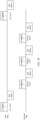
- FIG. 1b is a schematic diagram of a multi-link communication scenario according to an embodiment of this application.
- the AP MLD includes an AP 1, an AP 2, ..., and an AP n
- the non-AP MLD includes a STA 1, a STA 2, ..., and a STA n.
- n is a positive integer.
- the AP MLD and the non-AP MLD may communicate in parallel through a link 1, a link 2, ..., and a link n.
- the STA 1 in the non-AP MLD establishes an association relationship with the AP 1 in the AP MLD
- the STA 2 in the non-AP MLD establishes an association relationship with the AP 2 in the AP MLD
- the STAn in the non-AP MLD establishes an association relationship with the AP n in the AP MLD, and the like. Therefore, after the association relationship is established between one or more STAs in the non-AP MLD and one or more APs in the AP MLD, communication may be performed.
- FIG. 1c is a schematic diagram of a multi-link communication scenario according to an embodiment of this application. As shown in FIG. 1c , at least one AP and at least one STA are included. FIG. 1c shows two STAs, for example, a STA 1 and a STA2, and one non-AP MLD. For example, the non-AP MLD may communicate with the AP through two links, and the non-AP MLD includes two affiliated STAs, which are not shown in FIG. 1c . For another example, a STA 2 or a STA 3 may communicate with the AP through one link. To be specific, a system shown in FIG. 1c includes both multi-link communication and single-link communication.
- the method provided in this application may be applicable to, but is not limited to, single-user uplink/downlink transmission, multi-user uplink/downlink transmission, vehicle-to-everything (vehicle-to-everything, V2X, where X can represent anything), and device-to-device (device-to-device, D2D).
- vehicle-to-everything vehicle-to-everything, V2X, where X can represent anything
- device-to-device device-to-device
- the V2X may include: vehicle-to-vehicle (vehicle-to-vehicle, V2V), vehicle-to-infrastructure (vehicle-to-infrastructure, V2I), vehicle-to-pedestrian (vehicle-to-pedestrian, V2P), vehicle-to-network (vehicle-to-network, V2N), or the like.
- vehicle-to-vehicle vehicle-to-vehicle, V2V
- vehicle-to-infrastructure vehicle-to-infrastructure, V2I
- vehicle-to-pedestrian vehicle-to-pedestrian
- V2P vehicle-to-network
- V2N vehicle-to-network
- a transmitter shown below in this application may be understood as an MLD for sending data by using a block acknowledgment (block acknowledgment, BA) mechanism.
- the transmitter may also be referred to as an originator MLD (originator MLD), and a party that receives the data is referred to as a receiver.
- the receiver may also be referred to as a recipient MLD (recipient MLD).
- the transmitter may be a non-AP MLD, and the receiver may be an AP MLD.
- the transmitter may be an AP MLD, and the receiver may be a non-AP MLD.
- There may be a plurality of links between the transmitter and the receiver. Each link is used for communication between a STA affiliated with the originator MLD (a STA affiliated with the originator MLD) and a STA affiliated with the recipient MLD (a STA affiliated with the recipient MLD).
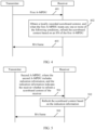
- FIG. 2 is a schematic flowchart of a multi-link communication method according to an embodiment of this application.
- the multi-link communication method is implemented based on a block acknowledgment (block acknowledgment, BA) mechanism.
- the BA mechanism may aggregate a plurality of "acknowledgments (acknowledgments)" into one frame, thereby improving channel efficiency.
- the method includes the following steps.
- a transmitter sends an add block acknowledgment (add BA, ADDBA) request (request) frame to a receiver.
- the receiver receives the ADDBA request frame.
- the receiver sends an ADDBA response (response) frame to the transmitter.
- the transmitter receives the ADDBA response frame.
- step 201 and step 202 it may be referred to as successful establishment of a BA protocol, successful establishment of the BA mechanism, or successful establishment of a BA session between the transmitter and the receiver.
- the transmitter sends an aggregate media access control protocol data unit (aggregate MPDU, A-MPDU) to the receiver.
- the receiver receives the A-MPDU.
- the transmitter may convert the plurality of MPDUs into one A-MPDU through aggregation.
- the receiver after receiving the A-MPDU, the receiver performs deaggregation control (deaggregation control) on the A-MPDU to obtain the plurality of MPDUs.
- deaggregation control deaggregation control
- each MPDU in the A-MPDU has a sequence number (sequence number, SN), and the SN indicates a sequence of each MPDU in the A-MPDU.
- a maximum quantity of MPDUs included in one A-MPDU may be 1024.
- a window size of a scoreboard may be changed, and may be determined through negotiation in interaction between the ADDBA request frame and the ADDBA response frame.
- the window size of the scoreboard may be 64, 128, 256, 512, 1024, or the like. Data aggregated by one A-MPDU does not exceed the window size of the scoreboard, but may be smaller than the window size of the scoreboard.
- the transmitter sends a BA request (BA request, BAR) frame to the receiver.
- the receiver receives the BAR frame.
- step 204 is shown by using an example in which the transmitter sends the BA request frame.
- the transmitter may further set an acknowledgment policy (ACK policy) in the sent A-MPDU to an implicit BAR (implicit BAR). Therefore, the transmitter may not need to separately send the BAR frame.
- ACK policy acknowledgment policy
- the receiver sends a BA frame to the transmitter based on the BAR frame, where the BA frame is used to acknowledge a receiving status of the MPDU in the A-MPDU.
- the transmitter receives the BA frame.
- the receiver needs to maintain a block acknowledgment record (BA record).
- the BA record includes a bitmap indexed based on sequence numbers, a start sequence number (which may be represented by WinStart R ) that is of a 12-bit unsigned integer and that may indicate a lowest sequence number location in the bitmap, a highest sequence number (which may be represented by WinEnd R ) in a current transmission window, and a maximum window size (for example, may be represented by WinSize R ).
- WinStart R represents a start sequence number of the scoreboard
- WinSize R represents a window size of the scoreboard (for example, may be 1024)
- WinEnd R represents an end sequence number of the scoreboard (a current end sequence number of the scoreboard).
- the receiver After obtaining the plurality of MPDUs based on the A-MPDU, the receiver performs a scoreboard context control (scoreboard context control) operation on each MPDU. After a score is recorded, the received MPDUs are delivered to a receive reordering buffer (receive reordering buffer), the MPDUs are sorted based on a sequence of SNs, and the correctly received MPDUs are delivered to an upper layer. If an MPDU that is not successfully received appears in the reordering process, an SN corresponding to the MPDU is marked as WinStart B , and all MPDUs that are successfully received in sequence and that are before the MPDU corresponding to the SN are delivered to the upper layer. For MPDUs after the SN, the receiver can deliver the correctly received MPDUs after the SN and the MPDU to the upper layer only after receiving the MPDU corresponding to the SN.
- a scoreboard context control scoreboard context control
- FIG. 3f is a schematic diagram of a scoreboard context control operation according to an embodiment of this application.
- a receiver after deaggregating one A-MPDU, a receiver obtains four MPDUs with SNs: 102, 103, 105, and 100.
- the receiver may record, in a scoreboard context, 1 at a bit location corresponding to the SN, where "1" indicates that the MPDU corresponding to the SN is correctly received, a bitmap (bitmap) is formed based on the scoring result, and the bitmap is placed in a BA frame as a corresponding acknowledgment of the A-MPDU.
- WinStart R 98
- WinSize R 12
- WinEnd R 109.
- Sequence number space of a BA record may include 4096 SNs, and a window of a scoreboard may be moved in the sequence number space.
- the scoreboard may be initialized. For example, WinStart R may be set to a start sequence number (start sequence number, SSN) provided by an ADDBA request frame.
- start sequence number start sequence number, SSN
- the receiver uses the SN to index the scoreboard and records correct reception of the MPDU.
- the receiver moves the window of the scoreboard to the right (which may be understood as: the receiver updates WinEnd R to make WinEnd R equal to the SN) until the rightmost edge of the window of the scoreboard includes the new SN.
- the window of the scoreboard is moved to the right, so that WinStart R is equal to an SSN provided by the BAR frame, and a BA frame with recorded content of the scoreboard is returned.
- the receiver checks whether the MPDU has a corresponding scoreboard record of the BA session.
- the BA session is identified by a transmitter address (transmitter address, TA) and a TID. If there is no scoreboard record, the receiver creates a scoreboard for the BA session, and may reuse memory of another session.
- each link between a transmitter and the receiver maintains respective scoreboard context control, and there is an MLD common scoreboard.
- Devices on each link (for example, each STAin an MLD, or each AP in the MLD) use respective scoreboard context control to feed back receiving statuses of MPDUs on the link.
- the common scoreboard may be used to record parameter information of a scoreboard on another link, for example, a start sequence number and/or an end sequence number of a scoreboard on each link, or record information (for example, WinStart B ) that integrates scoreboards of all links.
- an SN ranges from 0 to 4095.
- the SN is 4095, if the SN is increased by 1, the value of 4096 becomes 0. Therefore, numerical values of SNs in examples shown below in this application are obtained by performing a modulo operation on 4096.
- the receiver may perform an operation on the SN by using the modulo 4096, and each piece of SN space may be represented by a modulo 4096 counter.
- a transmitter may communicate with a receiver through two links, for example, a first link and a second link.
- a STA that is affiliated with the receiver and that is on the first link is referred to as a first STA
- a STA that is affiliated with the receiver and that is on the second link is referred to as a second STA.
- the first STA and the second STA are affiliated with a same MLD.
- FIG. 3a is a schematic diagram of a scoreboard context control operation according to an embodiment of this application.
- a same TID corresponds to four A-MPDUs
- an aggregation length of each A-MPDU is 1024, in other words, each A-MPDU includes 1024 MPDUs
- an acknowledgment policy of each A-MPDU is an immediate block acknowledgment.
- a first STA receives a 1 st A-MPDU (for example, an A-MPDU 1 shown in FIG. 3a ) with SNs from 0 to 1023.
- a second STA receives a 2 nd A-MPDU (for example, an A-MPDU 2 shown in FIG.
- the first STA receives a 4 th A-MPDU (for example, an A-MPDU 4 shown in FIG. 3a ) with SNs from 3072 to 4095. It may be understood that for description of relationships between A-MPDUs and SNs shown in FIG. 3b , refer to FIG. 3a . Details are not described one by one in the following.
- WinStart B 3072.
- embodiments of this application further provide a second type of scoreboard context control operation: if the following conditions are true:
- the recipient MLD shown above has separate scoreboard context control in each link, which may also be understood as: each STA affiliated with the recipient MLD maintains respective scoreboard context control.
- a STA refreshes a scoreboard context of the STA means that the STA initializes the scoreboard context of the STA, zeros out the scoreboard context of the STA, clears content already recorded in the scoreboard context, clears a cache of the scoreboard context, or the like. Updating the scoreboard context of the STA means that the STA may perform update based on the existing content in the scoreboard context.
- FIG. 3b is used as an example.
- the SNs of the 5 th A-MPDU received by the first STA meet 0 ⁇ SN ⁇ 1023.
- embodiments of this application provide a third type of scoreboard context control operation: if the following conditions are true:
- the STA affiliated with the recipient MLD may refresh the scoreboard context every time an MPDU is obtained. This manner has a problem of improperly flushing a local scoreboard.
- the STA receives an A-MPDU.
- the A-MPDU includes a first MPDU and a second MPDU, and a local scoreboard context may be flushed for one time based on an SN of the first MPDU.
- a scoreboard context, of a BA frame that is not fed back, related to the SN of the first MPDU is flushed. Because after the STA flushes the local scoreboard context based on the SN 1 of the first MPDU, the STA does not feed back the BA frame. In this case, if the local scoreboard context is flushed for another time based on the second MPDU, the STA cannot correctly feed back the BA frame.
- embodiments of this application provide a fourth type of scoreboard context control operation: if the following conditions are true:
- the STA may refresh a scoreboard context of the STA based on a 1 st MPDU that is in the A-MPDU and that meets all the conditions other than the last condition. It may also be said that the STA cannot refresh the scoreboard context of the STA based on an SN of a non-1 st MPDU that is in the A-MPDU and that meets all the conditions other than the last condition.
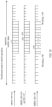
- FIG. 3d A schematic diagram shown in FIG. 3d is used as an example. After a first STAreceives two A-MPDUs with SNs from 500 to 1023 and with SNs from 0 to 499, because both the two A-MPDUs meet the foregoing second type of scoreboard context control operation, the first STA performs flushing separately for two times. For example, when the local scoreboard context is flushed after the A-MPDU with SNs from 0 to 499 is received, a BA record, of a BA frame that is not replied, and with SNs from 500 to 1023 is also flushed.
- ACK policy indicates that the first STA does not need to feed back the BA frame temporarily
- a 2 nd acknowledgment policy (which may also be referred to as an implicit BAR) shown in FIG. 3d indicates that the first STA needs to feed back the BA frame.
- embodiments of this application further provide a fifth type of scoreboard context control operation: if the following conditions are true:
- the STA when a STA successively receives two A-MPDUs, and when an SN of an MPDU in a 1 st A-MPDU satisfies WinStart R ⁇ SN ⁇ WinEnd R , the STA may refresh a scoreboard context of the STA.
- the STA does not feed back a BA frame of the 1 st A-MPDU, even if an SN of an MPDU in a 2 nd A-MPDU satisfies the foregoing conditions, the STA does not refresh the scoreboard context of the STA, but may update the scoreboard context of the STA.
- FIG. 3e A schematic diagram shown in FIG. 3e is used as an example. After a first STAreceives an A-MPDU with SNs from 200 to 299, the A-MPDU meets the foregoing second type of scoreboard context control operation, and a scoreboard context in the first STA is refreshed. However, in the scenario shown in FIG. 3e , according to an SN relationship between a 1 st A-MPDU, a 3 rd A-MPDU, and a 4 th A-MPDU, the first STA does not need to perform flushing.
- embodiments of this application provide a sixth type of scoreboard context control operation: if the following conditions are true:
- the STA may refresh the scoreboard context of the STA.
- FIG. 3e is used as an example.
- WinEnd R 199
- WinStart B 200.
- the scoreboard context of the first STA is not updated. It is similar for a 4 th A-MPDU. This is not listed one by one.
- third type of scoreboard context control operation to the sixth type of scoreboard context control operation described above may be implemented separately, or may be combined with each other.
- third type of scoreboard context control operation and the fourth type of scoreboard context control operation may be combined to obtain, for example, a seventh type of scoreboard context control operation: if the following conditions are true:
- the seventh type of scoreboard context control operation can resolve both the problem shown in FIG. 3c above, and the problem of refreshing the scoreboard context for each MPDU shown above.
- the third type of scoreboard context control operation and the fifth type of scoreboard context control operation may be combined to obtain, for example, an eighth type of scoreboard context control operation: if the following conditions are true:
- the third type of scoreboard context control operation, the fourth type of scoreboard context control operation, and the fifth type of scoreboard context control operation may be combined to obtain, for example, a ninth type of scoreboard context control operation: if the following conditions are true:
- the third type of scoreboard context control operation, the fourth type of scoreboard context control operation, the fifth type of scoreboard context control operation, and the sixth type of scoreboard context control operation may be combined to obtain, for example, a tenth type of scoreboard context control operation: if the following conditions are true:
- the tenth type of scoreboard context control operation described above may be further understood as: if the following conditions are true:
- FIG. 3a to FIG. 3e are all shown by using an example in which one A-MPDU includes a plurality of MPDUs, and each SN may correspond to one MPDU. It may be understood that, in this application, the SNs of the A-MPDUs shown above are all shown by using an example in which the SNs belong to a same TID.
- an embodiment of this application provides a multi-link communication method.
- the multi-link communication method includes the following steps.
- the transmitter sends a first A-MPDU to the receiver, and the receiver receives the first A-MPDU.
- the first A-MPDU may include one MPDU.
- the first A-MPDU may include at least two MPDUs.
- the A-MPDU is carried in a PPDU.
- one PPDU carries only one A-MPDU. Therefore, the A-MPDU in this embodiment of this application may be further understood as the PPDU. This is not limited in this embodiment of this application.
- the receiver obtains a locally recorded scoreboard context, and when the first A-MPDU meets any one or more of the following conditions, refreshes the scoreboard context based on an SN of the first A-MPDU.
- the locally recorded scoreboard context in this embodiment of this application may be an initialized scoreboard context, a scoreboard context updated by the receiver based on an A-MPDU that has been received by the receiver before the first A-MPDU is received, a scoreboard context refreshed by the receiver based on an A-MPDU that has been received by the receiver before the first A-MPDU is received, or the like. This is not listed one by one herein.
- Conditions that the first A-MPDU meets include:
- a sequence of performing the first condition to the third condition by the STA is not limited in this embodiment of this application.
- the first A-MPDU meets any one of the first condition to the fourth condition described above, for another condition met by the first A-MPDU, refer to related descriptions of the third type of scoreboard context control operation to the sixth type of scoreboard context control operation described above.
- the first A-MPDU meets any two of the first condition to the fourth condition described above, for another condition met by the first A-MPDU, refer to related descriptions of the sixth type of scoreboard context control operation to the ninth type of context control operation described above.
- the first A-MPDU meets the first condition to the fourth condition described above, for another condition met by the first A-MPDU, refer to related descriptions of the tenth type of scoreboard context control operation described above.
- the receiver sends a BA frame to the transmitter, where the BA frame is used to acknowledge a receiving status of the MPDU in the first A-MPDU.
- the receiver can properly and effectively refresh a local scoreboard (local scoreboard) context.
- the receiver may refresh or update the local scoreboard context based on the third type of scoreboard context control operation to the tenth type of scoreboard context control operation.
- An embodiment of this application further provides a multi-link communication method.
- a transmitter may indicate, by using indication information, whether a receiver refreshes a local scoreboard context, thereby effectively reducing complexity of the receiver.
- FIG. 5 is a schematic flowchart of another multi-link communication method according to an embodiment of this application.
- the multi-link communication method includes the following steps.
- the transmitter sends a second A-MPDU to the receiver, where the second A-MPDU includes indication information, and the indication information indicates the receiver whether to refresh a scoreboard context of the receiver.
- the receiver receives the second A-MPDU.
- a STA at the receiver is capable of using reordering buffer information to update the scoreboard context.
- a STA at the receiver may be capable of updating the scoreboard context by using the reordering buffer information, or may not be capable of updating the scoreboard context by using the reordering buffer information.
- the indication information when the indication information is set to 0, it may indicate that the receiver does not need to refresh the local scoreboard context. For another example, when the indication information is set to 1, it indicates that the receiver needs to refresh the local scoreboard context, or may implicitly indicate that the receiver is capable of refreshing the local scoreboard context.
- the second A-MPDU is transmitted through a link, and a STA receiving the A-MPDU on the link is unique. Therefore, the STA corresponding to the link used to transmit the second A-MPDU may determine, based on the indication information, whether to refresh the local scoreboard context.
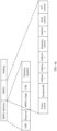
- FIG. 6a is a schematic diagram of a structure of an MPDU subframe according to an embodiment of this application.
- indication information may be carried in a reserved (reserved) field in an MPDU delimiter (delimiter), or carried in a high throughput (high throughput, HT) control (HT control) field.
- delimiter MPDU delimiter
- HT control high throughput control
- the HT control field may be carried in an MPDU (for example, quality of service (quality of service, QoS) data (data) frame, a quality of service null (QoS null) frame, and a management frame) to carry some control information.
- a length of the HT control field is 4 bytes.
- a corresponding HT control field is an HT control field of a high efficiency (high efficiency, HE) type.
- Table 1 Variant B0 B1 B2 to B29 B30 B31 HT 0 Middle part of the HT control field AC constraint RDG/More PPDU VHT 1 0 Middle part of the VHT control field AC constraint RDG/More PPDU HE 1 1 Aggregation control field A-Control
- FIG. 6b is a schematic diagram of a format of an aggregation control field according to an embodiment of this application.
- the aggregation control field includes a control list (control list) and a padding (padding) part.
- a bit length of the control list is variable, and the control list may include one or more control subfields (control subfields).
- the padding part includes 0 or more bits.
- FIG. 6c is a schematic diagram of a format of a control subfield in an aggregation control field according to an embodiment of this application.
- One control subfield includes a 4-bit control identifier (control ID) and control information (control information).
- the control identifier is used to identify the control information.
- the control identifier and a length of the corresponding control information are shown in Table 2.
- Table 2 Control identifier value Meaning Length (bit) of the control information Content of the control information 0
- Triggered response scheduling (Triggered response scheduling, TRS) 26 Refer to 9.2.4.6a.1 (TRS control) 1
- Operating mode (operating mode, OM) 12 Refer to 9.2.4.6a.2 (OM control) 2
- High efficiency link adaptation (HE link adaptation, HLA) 26 Refer to 9.2.4.6a.3 (HLA control) 3
- Buffer status report (buffer status report, BSR) 26 Refer to 9.2.4.6a.4 (BSR control) 4
- Uplink power headroom (UL power headroom, UPH) 8 Refer to 9.2.4.6a.5 (UPH control) 5
- Bandwidth query report (Bandwidth query report, BQR) 10 Refer to 9.2.4.6a.6 (BQR control) 6
- an end of frame end of frame
- EOF end of frame
- reversed reversed
- MPDU length length
- CRC cyclic redundancy check
- delimiter signature delimiter signature
- frame control frame control
- duration/identifier duration/identifier
- address 1 address 1
- address 4 address 4
- sequence control sequence control
- QoS control QoS control
- HT control HT control
- padding padding
- this embodiment of this application provides two HE types of HT control fields that can carry the indication information.
- a first method is implementing the indication information by using a reserved (reversed) bit in CAS type control information.
- a frame structure of the CAS type control information is shown in FIG. 6d .
- the CAS type control information may include an access category (access category, AC) constraint (AC constraint) field, a reverse direct grant (reverse direct grant, RDG) field, a parameterized spatial reuse transmission (parameterized spatial reuse transmission, PSRT) PPDU field, and a reserved (reserved) field.
- AC access category
- RDG reverse direct grant
- PSRT parameterized spatial reuse transmission
- PSRT reserved (reserved) field.
- a second method is establishing a new control type (as shown in FIG. 6c ) by using a currently reserved control identifier (control ID), and indicate the new control type by using control information of the new control type.
- control ID a currently reserved control identifier
- a bit length of the indication information may be 1 bit.
- the receiver refreshes the scoreboard context based on the indication information.
- the receiver may alternatively not refresh the scoreboard context based on the indication information. For example, the receiver may update the scoreboard context.
- the receiver sends a BA frame to the transmitter, and the transmitter receives the BA frame.
- the transmitter adds the indication information to the A-MPDU to indicate the receiver to refresh the scoreboard context. This can effectively reduce complexity of the receiver and improve efficiency of refreshing the scoreboard context by the receiver.
- An embodiment of this application further provides a multi-link communication method.
- a STA at a receiver may be capable of updating a scoreboard context by using reordering buffer information, or may not be capable of updating the scoreboard context by using the reordering buffer information.
- a transmitter includes a first field in a transmitted data frame (that is, an A-MPDU), and the first field indicates a round of transmission of a current SN.
- the first field may be referred to as a round of SN subfield (Round of SN subfield), and an initial value of the field is set to 0.
- a round of SN subfield Redund of SN subfield
- an initial value of the field is set to 0.
- the value of the round of SN subfield is increased by 1.
- a value of the round of SN subfield may be from 0 to 31. For example, if the value of the round of SN subfield is set to 31, the value is returned to 0 if the value is increased by 1.
- the receiver may refresh a local scoreboard context before updating the local scoreboard context if the following conditions are met:
- the round of SN subfield may be included in the newly created HT control type of the HE type shown in FIG. 5 (a new control type is newly created by using the unused IDs in the first column shown in Table 2, as shown in FIG. 6c ).
- a bit length of the round of SN subfield is not limited in this embodiment of this application, for example, may be five bits.
- the round of SN subfield may be carried by using a newly created A-control type, or carried in a reserved bit of a CAS control type. For example, refer to a bearer location of the indication information shown in FIG. 5 .
- the receiver may not be able to determine whether the value of the round of SN subfield changes. However, provided that the length of the round of SN subfield is long enough, a probability of occurrence of this situation is very low, which may be ignored as a low probability event.
- An embodiment of this application further provides a type of scoreboard context control operation, as described in the following:
- a STA affiliated with a recipient MLD is not capable of using reordering buffer information to update a scoreboard context of the STA and the recipient MLD has separate scoreboard context control in each link, the STA needs to implement a partial-state operation (which means a partial state operation of a BA mechanism), and discard temporary records in the following defined time periods:
- the third type of scoreboard context control operation is used as an example.
- a scoreboard of the frame needs to be flushed.
- Q is equal to 2, or Q may be equal to 3.
- WinStart R ⁇ SN ⁇ WinStart R +2 11 may also be understood as WinStart R ⁇ SN ⁇ WinStart R +2 11 -1.
- the following WinStart R ⁇ SN ⁇ WinStart R +2*WinSize R may also be understood as WinStart R ⁇ SN ⁇ WinStart R +2*WinSize R -1 or WinStart R ⁇ SN ⁇ WinEnd R +WinSize R .
- a range that an SN meets in this application may be adjusted based on a specific range (for example, a range from -2 to +2). This is not listed one by one herein.
- WinStart R ⁇ SN ⁇ WinStart R +2*WinSize R -1 as an example for description.
- the first STA does not receive a 6 th A-MPDU (for example, an A-MPDU 6 shown in FIG. 10a )
- the receiver receives the 6 th A-MPDU, because SNs are from 256 to 400, the SNs of the 6 th A-MPDU neither belong to the foregoing first type of scoreboard context control operation, nor belong to the foregoing second type of scoreboard context control operation. Therefore, the first STA cannot learn how to update the scoreboard context of the first STA.
- the receiver when receiving the 6 th A-MPDU, the receiver directly moves WinEnd R of the scoreboard of the first STA to a location of 767, and WinStart R is at 512.
- the BA frame is fed back, status information of any frame within a range of 0 to 255 in the previous round is not incorrectly fed back. Therefore, the scoreboard does not need to be flushed for the 6 th A-MPDU.
- ellipses omit other A-MPDUs that are not shown.
- this application further provides an eleventh type of scoreboard context control operation. if the following conditions are true:
- the communication apparatus may be divided into functional modules based on the foregoing method embodiments.
- functional modules may be obtained through division based on corresponding functions, or two or more functions may be integrated into one processing module.
- the integrated module may be implemented in a form of hardware, or may be implemented in a form of a software functional module.
- the module division is used as an example, and is merely a logical function division. In actual implementation, another division manner may be used. The following describes in detail communication apparatuses in embodiments of this application with reference to FIG. 7 to FIG. 9 .
- FIG. 7 is a schematic diagram of a structure of a communication apparatus according to an embodiment of this application.
- the communication apparatus includes a processing unit 701 and a transceiver unit 702.
- the communication apparatus may be the transmitter shown above.
- the communication apparatus shown in FIG. 7 may be configured to perform steps, functions, and the like performed by the transmitter in the foregoing method embodiments.
- the transceiver unit 702 is configured to: send an ADDBA request frame, and receive an ADDBA response frame.
- the transceiver unit 702 is further configured to send a first A-MPDU.
- the transceiver unit 702 is further configured to: send a BAR frame, and receive a BA frame.
- the transceiver unit 702 is further configured to send a second A-MPDU.
- transceiver unit and the processing unit in this embodiment of this application are merely examples.
- functions or steps performed by the transceiver unit and the processing unit refer to the foregoing method embodiments (for example, FIG. 4 and FIG. 5 are included). Details are not described herein again.
- FIG. 7 is reused.
- the communication apparatus may be the receiver shown above.
- the communication apparatus shown in FIG. 7 may be configured to perform steps, functions, and the like performed by the receiver in the foregoing method embodiments.
- the transceiver unit 702 is configured to: receive an ADDBA request frame, and send an ADDBA response frame.
- the transceiver unit 702 is further configured to receive a first A-MPDU.
- the processing unit 701 is configured to: obtain a locally recorded scoreboard context, and when the first A-MPDU meets at least one of the third type of scoreboard context control operation to the tenth type of scoreboard context control operation shown in embodiments of this application, refresh the scoreboard context based on an SN of the first A-MPDU.
- the transceiver unit 702 is further configured to: receive a BAR frame, and send a BA frame.
- the transceiver unit 702 is further configured to receive a second A-MPDU.
- the processing unit 701 is further configured to refresh the scoreboard context based on indication information in the second A-MPDU.
- transceiver unit and the processing unit in this embodiment of this application are merely examples.
- functions or steps performed by the transceiver unit and the processing unit refer to the foregoing method embodiments (for example, FIG. 4 and FIG. 5 are included). Details are not described herein again.
- the processing unit 701 may be one or more processors.
- the transceiver unit 702 may be a transceiver, or the transceiver unit 702 may be a sending unit and a receiving unit.
- the sending unit may be a transmitter, and the receiving unit may be a receiver.
- the sending unit and the receiving unit are integrated in one component, for example, a transceiver.
- the processor and the transceiver may be coupled, and a connection manner between the processor and the transceiver is not limited in this embodiment of this application.
- a communication apparatus 80 includes one or more processors 820 and a transceiver 810.
- the transceiver 810 when the communication apparatus is configured to perform the steps, methods, or functions performed by the transmitter, for example, the transceiver 810 is configured to: send an ADDBA request frame, and receive an ADDBA response frame. For another example, the transceiver 810 is further configured to send a first A-MPDU. For another example, the transceiver 810 is further configured to: send a BAR frame, and receive a BA frame. For another example, the transceiver 810 is further configured to send a second A-MPDU.
- the transceiver 810 when the communication apparatus is configured to perform the steps, methods, or functions performed by the receiver, for example, the transceiver 810 is configured to: receive an ADDBA request frame, and send an ADDBA response frame. For another example, the transceiver 810 is further configured to receive a first A-MPDU. For another example, the processor 820 is configured to: obtain a locally recorded scoreboard context, and when the first A-MPDU meets at least one of the third type of scoreboard context control operation to the tenth type of scoreboard context control operation shown in embodiments of this application, refresh the scoreboard context based on an SN of the first A-MPDU. For another example, the transceiver 810 is further configured to: receive a BAR frame, and send a BA frame. For another example, the transceiver 810 is further configured to receive a second A-MPDU. The processor 820 is further configured to refresh the scoreboard context based on indication information in the second A-MPDU.
- processor and the transceiver refer to descriptions of the processing unit and the transceiver unit shown in FIG. 7 . Details are not described herein again.
- the transceiver may include a receiver and a transmitter.
- the receiver is configured to perform a function (or operation) of receiving
- the transmitter is configured to perform a function (or operation) of transmitting.
- the transceiver is configured to communicate with another device/apparatus by using a transmission medium.
- the communication apparatus 80 may further include one or more memories 830, configured to store program instructions and/or data.
- the memory 830 is coupled to the processor 820.
- the coupling in embodiments of this application may be an indirect coupling or a communication connection between apparatuses, units, or modules in an electrical form, a mechanical form, or another form, and is used for information exchange between the apparatuses, the units, or the modules.
- the processor 820 may cooperate with the memory 830.
- the processor 820 may execute the program instructions stored in the memory 830.
- at least one of the one or more memories may be included in the processor.
- a specific connection medium between the transceiver 810, the processor 820, and the memory 830 is not limited in this embodiment of this application.
- the memory 830, the processor 820, and the transceiver 810 are connected to each other through a bus 840 in FIG. 8 .
- the bus is represented by using a thick line in FIG. 8 .
- a connection manner between other components is merely an example for description, and is not limited thereto.
- the bus may be classified into an address bus, a data bus, a control bus, and the like. For ease of representation, only one bold line is used for representation in FIG. 8 , but this does not mean that there is only one bus or only one type of bus.
- the processor may be a general-purpose processor, a digital signal processor, an application-specific integrated circuit, a field programmable gate array or another programmable logic device, a discrete gate or transistor logic device, or a discrete hardware component, and may implement or execute the methods, steps, and logical block diagrams disclosed in embodiments of this application.
- the general-purpose processor may be a microprocessor or any conventional processor or the like. The steps of the method disclosed in embodiments of this application may be directly performed by a hardware processor, or may be performed by using a combination of hardware and software modules in the processor.
- the memory may include but is not limited to a non-volatile memory, for example, a hard disk drive (hard disk drive, HDD) or a solid-state drive (solid-state drive, SSD), a random access memory (random access memory, RAM), an erasable programmable read-only memory (erasable programmable ROM, EPROM), a read-only memory (read-only memory, ROM), or a compact disc read-only memory (compact disc read-only memory, CD-ROM).
- the memory is any other medium that can carry or store program code in a form of instructions or a data structure and that can be read and/or written by a computer (for example, the communication apparatus shown in this application), but is not limited thereto.
- the memory in this embodiment of this application may alternatively be a circuit or any other apparatus that can implement a storage function, and is configured to store the program instructions and/or the data.
- the processor 820 is mainly configured to: process a communication protocol and communication data, control the entire communication apparatus, execute a software program, and process data of the software program.
- the memory 830 is mainly configured to store the software program and the data.
- the transceiver 810 may include a control circuit and an antenna.
- the control circuit is mainly configured to: perform conversion between a baseband signal and a radio frequency signal, and process the radio frequency signal.
- the antenna is mainly configured to send and receive a radio frequency signal in a form of an electromagnetic wave.
- An input/output apparatus for example, a touchscreen, a display, a keyboard, or the like is mainly configured to: receive data input by a user, and output data to the user.
- the processor 820 may read the software program in the memory 830, interpret and execute instructions of the software program, and process the data of the software program.
- the processor 820 outputs a baseband signal to a radio frequency circuit.
- the radio frequency circuit After performing radio frequency processing on the baseband signal, the radio frequency circuit sends a radio frequency signal in the form of the electromagnetic wave through the antenna.
- the radio frequency circuit receives a radio frequency signal through the antenna, converts the radio frequency signal into a baseband signal, and outputs the baseband signal to the processor 820.
- the processor 820 converts the baseband signal into data, and processes the data.
- the radio frequency circuit and the antenna may be disposed independently of a processor that performs baseband processing.
- the radio frequency circuit and the antenna may be remotely disposed independent of the communication apparatus.
- the communication apparatus shown in this embodiment of this application may further have more components and the like than those in FIG. 8 . This is not limited in this embodiment of this application.
- the foregoing methods performed by the processor and the transceiver are merely examples. For specific steps performed by the processor and the transceiver, refer to the methods described above.
- the processing unit 701 may be one or more logic circuits, and the transceiver unit 702 may be an input/output interface, or referred to as a communication interface, an interface circuit, an interface, or the like.
- the transceiver unit 702 may be a sending unit and a receiving unit.
- the sending unit may be an output interface
- the receiving unit may be an input interface.
- the sending unit and the receiving unit are integrated into one unit, for example, an input/output interface.
- the communication apparatus shown in FIG. 9 includes a logic circuit 901 and an interface 902.
- the processing unit 701 may be implemented by using the logic circuit 901, and the transceiver unit 702 may be implemented by using the interface 902.
- the logic circuit 901 may be a chip, a processing circuit, an integrated circuit, a system on chip (system on chip, SoC) chip, or the like.
- the interface 902 may be a communication interface, an input/output interface, a pin, or the like.
- FIG. 9 is an example in which the foregoing communication apparatus is used as a chip.
- the chip includes the logic circuit 901 and the interface 902.
- the logic circuit and the interface may be further coupled to each other.
- a specific connection manner of the logical circuit and the interface is not limited in this embodiment of this application.
- the interface 902 when the communication apparatus is configured to perform the methods, functions, or steps performed by the transmitter, for example, the interface 902 is configured to: send an ADDBA request frame, and receive an ADDBA response frame. For another example, the interface 902 is further configured to send a first A-MPDU. For another example, the interface 902 is further configured to: send a BAR frame, and receive a BA frame. For another example, the interface 902 is further configured to send a second A-MPDU.
- the interface 902 when the communication apparatus is configured to perform the methods, functions, or steps performed by the receiver, for example, the interface 902 is configured to: receive an ADDBA request frame, and send an ADDBA response frame. For another example, the interface 902 is further configured to receive a first A-MPDU. For another example, the logic circuit 901 is configured to: obtain a locally recorded scoreboard context, and when the first A-MPDU meets at least one of the third type of scoreboard context control operation to the tenth type of scoreboard context control operation shown in embodiments of this application, refresh the scoreboard context based on an SN of the first A-MPDU. For another example, the interface 902 is further configured to: receive a BAR frame, and send a BA frame. For another example, the interface 902 is further configured to receive a second A-MPDU. The logic circuit 901 is further configured to refresh the scoreboard context based on indication information in the second A-MPDU.
- the communication apparatus shown in embodiments of this application may implement the methods provided in embodiments of this application in a form of hardware, or may implement the methods provided in embodiments of this application in a form of software. This is not limited in embodiments of this application.
- An embodiment of this application further provides a wireless communication system.
- the wireless communication system includes a transmitter and a receiver.
- the transmitter and the receiver may be configured to perform the method in any one of the foregoing embodiments (as shown in FIG. 4, FIG. 5 , and the like).
- this application further provides a computer program.
- the computer program is used to implement an operation and/or processing performed by the transmitter in the method provided in this application.
- This application further provides a computer program.
- the computer program is used to implement an operation and/or processing performed by the receiver in the method provided in this application.
- This application further provides a computer-readable storage medium.
- the computer-readable storage medium stores computer code.
- the computer code When the computer code is run on a computer, the computer is enabled to perform an operation and/or processing performed by the transmitter in the method provided in this application.
- This application further provides a computer-readable storage medium.
- the computer-readable storage medium stores computer code.
- the computer code When the computer code is run on a computer, the computer is enabled to perform an operation and/or processing performed by the receiver in the method provided in this application.
- the computer program product includes computer code or a computer program.
- the computer code or the computer program runs on a computer, an operation and/or processing performed by the transmitter in the method provided in this application is enabled to be performed.
- the computer program product includes computer code or a computer program.
- the computer code or the computer program runs on a computer, an operation and/or processing performed by the receiver in the method provided in this application is enabled to be performed.
- the disclosed systems, apparatuses, and methods may be implemented in other manners.
- the described apparatus embodiments are merely examples.
- division into the units is merely logical function division and may be other division in actual implementation.
- a plurality of units or components may be combined or integrated into another system, or some features may be ignored or not performed.
- the displayed or discussed mutual couplings or direct couplings or communication connections may be implemented through some interfaces.
- the indirect couplings or communication connections between the apparatuses or units may be implemented in electrical, mechanical, or other forms.
- the units described as separate parts may or may not be physically separate, and parts displayed as units may or may not be physical units, may be located in one position, or may be distributed on a plurality of network units. Some or all of the units may be selected based on an actual requirement to implement technical effects of the solutions provided in embodiments of this application.
- functional units in embodiments of this application may be integrated into one processing unit, or each of the units may exist alone physically, or two or more units may be integrated into one unit.
- the integrated unit may be implemented in a form of hardware, or may be implemented in a form of a software function unit.
- the integrated unit When the integrated unit is implemented in the form of the software functional unit and is sold or used as an independent product, the integrated unit may be stored in a computer-readable storage medium. Based on such an understanding, the technical solutions of embodiments of this application essentially, or the part contributing to the conventional technology, all or some of the technical solutions may be implemented in a form of a software product.
- the computer software product is stored in a readable-storage medium, and includes several instructions for instructing a computer device (which may be a personal computer, a server, or a network device) to perform all or some of the steps of the methods described in embodiments of this application.
- the foregoing readable-storage medium includes any medium that can store program code, such as a USB flash drive, a removable hard disk, a read-only memory (read-only memory, ROM), a random access memory (random access memory, RAM), a magnetic disk, or an optical disc.
- program code such as a USB flash drive, a removable hard disk, a read-only memory (read-only memory, ROM), a random access memory (random access memory, RAM), a magnetic disk, or an optical disc.
Landscapes
- Engineering & Computer Science (AREA)
- Computer Networks & Wireless Communication (AREA)
- Signal Processing (AREA)
- Computer Security & Cryptography (AREA)
- Mobile Radio Communication Systems (AREA)
Applications Claiming Priority (3)
| Application Number | Priority Date | Filing Date | Title |
|---|---|---|---|
| CN202210076088 | 2022-01-23 | ||
| CN202210109328.1A CN116545918A (zh) | 2022-01-23 | 2022-01-28 | 多链路通信方法及装置 |
| PCT/CN2023/071022 WO2023138414A1 (zh) | 2022-01-23 | 2023-01-06 | 多链路通信方法及装置 |
Publications (2)
| Publication Number | Publication Date |
|---|---|
| EP4456504A1 true EP4456504A1 (de) | 2024-10-30 |
| EP4456504A4 EP4456504A4 (de) | 2025-04-16 |
Family
ID=87347789
Family Applications (1)
| Application Number | Title | Priority Date | Filing Date |
|---|---|---|---|
| EP23742729.9A Pending EP4456504A4 (de) | 2022-01-23 | 2023-01-06 | Verfahren und vorrichtung zur mehrfachverbindungskommunikation |
Country Status (8)
| Country | Link |
|---|---|
| US (1) | US20240381476A1 (de) |
| EP (1) | EP4456504A4 (de) |
| JP (1) | JP7741333B2 (de) |
| KR (1) | KR20240134984A (de) |
| AU (1) | AU2023209486B2 (de) |
| CA (1) | CA3249380A1 (de) |
| MX (1) | MX2024009061A (de) |
| WO (1) | WO2023138414A1 (de) |
Family Cites Families (5)
| Publication number | Priority date | Publication date | Assignee | Title |
|---|---|---|---|---|
| US11451337B2 (en) * | 2018-07-30 | 2022-09-20 | Nxp Usa, Inc. | Media access control for punctured/aggregated communication channels in WLAN |
| CN110601988B (zh) * | 2019-09-11 | 2022-09-27 | 紫光展讯通信(惠州)有限公司 | 基于802.11协议的数据接收方法及装置、存储介质、终端 |
| SG10201912856TA (en) * | 2019-12-20 | 2021-07-29 | Panasonic Ip Corp America | Communication device and communication method for multi-link block acknowledgement |
| US20210111836A1 (en) * | 2020-02-14 | 2021-04-15 | Po-Kai Huang | Block acknowledgement reception window size for eht networks |
| US11743709B2 (en) * | 2020-04-08 | 2023-08-29 | Qualcomm Incorporated | Context updates for multi-link devices |
-
2023
- 2023-01-06 EP EP23742729.9A patent/EP4456504A4/de active Pending
- 2023-01-06 WO PCT/CN2023/071022 patent/WO2023138414A1/zh not_active Ceased
- 2023-01-06 JP JP2024543338A patent/JP7741333B2/ja active Active
- 2023-01-06 AU AU2023209486A patent/AU2023209486B2/en active Active
- 2023-01-06 KR KR1020247027393A patent/KR20240134984A/ko active Pending
- 2023-01-06 CA CA3249380A patent/CA3249380A1/en active Pending
- 2023-01-06 MX MX2024009061A patent/MX2024009061A/es unknown
-
2024
- 2024-07-19 US US18/777,876 patent/US20240381476A1/en active Pending
Also Published As
| Publication number | Publication date |
|---|---|
| AU2023209486A1 (en) | 2024-08-01 |
| JP7741333B2 (ja) | 2025-09-17 |
| US20240381476A1 (en) | 2024-11-14 |
| KR20240134984A (ko) | 2024-09-10 |
| MX2024009061A (es) | 2024-07-29 |
| WO2023138414A1 (zh) | 2023-07-27 |
| AU2023209486B2 (en) | 2026-02-19 |
| EP4456504A4 (de) | 2025-04-16 |
| CA3249380A1 (en) | 2025-02-28 |
| JP2025504493A (ja) | 2025-02-12 |
Similar Documents
| Publication | Publication Date | Title |
|---|---|---|
| US12375210B2 (en) | Method for determining receiving status of data frame and communication apparatus | |
| US10122499B2 (en) | Method and apparatus for ACK transmission in a WLAN | |
| US20210227529A1 (en) | Method and apparatus for communications | |
| US12355569B2 (en) | Communication method and apparatus | |
| US20210111836A1 (en) | Block acknowledgement reception window size for eht networks | |
| US20060136614A1 (en) | System and method for variable length aggregate acknowledgements in a shared resource network | |
| US20070058566A1 (en) | Fast Control Messaging Mechanism For Use In Wireless Network Communications | |
| CN110024435B (zh) | 无线通信装置及无线通信方法 | |
| AU2021238794A1 (en) | Data transmission method and apparatus | |
| CN115769524B (zh) | 多连接下的通信方法和通信装置 | |
| EP4340246A1 (de) | Uplink-datensendeverfahren, uplink-datenempfangsverfahren und kommunikationsvorrichtung | |
| CN113014366A (zh) | 控制信息指示方法及网元 | |
| WO2017067253A1 (zh) | 基于业务类型指示的确认方法及装置 | |
| EP3790213B1 (de) | Mac-basierte hybride automatische wiederholungsanforderung (harq) | |
| CN102752086B (zh) | 数据通信装置和数据通信方法 | |
| AU2023209486B2 (en) | Multi-link communication method and apparatus | |
| CN116545918A (zh) | 多链路通信方法及装置 | |
| EP3968554A1 (de) | Verfahren und vorrichtung zur erneuten übertragung | |
| CN116634507B (zh) | 多链路通信方法及装置 | |
| EP4340270B1 (de) | Verfahren zur durchführung einer adaptiven mehrfachverbindungsaggregationsabfertigungssteuerung in einer mehrfachverbindungsbetriebsarchitektur und zugehörige vorrichtung | |
| CN120881768A (zh) | 一种通信方法及装置 |
Legal Events
| Date | Code | Title | Description |
|---|---|---|---|
| STAA | Information on the status of an ep patent application or granted ep patent |
Free format text: STATUS: THE INTERNATIONAL PUBLICATION HAS BEEN MADE |
|
| PUAI | Public reference made under article 153(3) epc to a published international application that has entered the european phase |
Free format text: ORIGINAL CODE: 0009012 |
|
| STAA | Information on the status of an ep patent application or granted ep patent |
Free format text: STATUS: REQUEST FOR EXAMINATION WAS MADE |
|
| 17P | Request for examination filed |
Effective date: 20240722 |
|
| AK | Designated contracting states |
Kind code of ref document: A1 Designated state(s): AL AT BE BG CH CY CZ DE DK EE ES FI FR GB GR HR HU IE IS IT LI LT LU LV MC ME MK MT NL NO PL PT RO RS SE SI SK SM TR |
|
| REG | Reference to a national code |
Ref country code: DE Ref legal event code: R079 Free format text: PREVIOUS MAIN CLASS: H04L0045240000 Ipc: H04L0001182900 |
|
| A4 | Supplementary search report drawn up and despatched |
Effective date: 20250314 |
|
| RIC1 | Information provided on ipc code assigned before grant |
Ipc: H04L 45/24 20220101ALI20250310BHEP Ipc: H04L 1/1607 20230101ALI20250310BHEP Ipc: H04L 1/1829 20230101AFI20250310BHEP |
|
| DAV | Request for validation of the european patent (deleted) | ||
| DAX | Request for extension of the european patent (deleted) |