EP4456441A1 - Verfahren und vorrichtung zum senden und empfangen eines drahtlosen signals in einem drahtloskommunikationssystem - Google Patents
Verfahren und vorrichtung zum senden und empfangen eines drahtlosen signals in einem drahtloskommunikationssystem Download PDFInfo
- Publication number
- EP4456441A1 EP4456441A1 EP22911850.0A EP22911850A EP4456441A1 EP 4456441 A1 EP4456441 A1 EP 4456441A1 EP 22911850 A EP22911850 A EP 22911850A EP 4456441 A1 EP4456441 A1 EP 4456441A1
- Authority
- EP
- European Patent Office
- Prior art keywords
- tci
- dci
- coreset
- transmission
- list
- Prior art date
- Legal status (The legal status is an assumption and is not a legal conclusion. Google has not performed a legal analysis and makes no representation as to the accuracy of the status listed.)
- Pending
Links
Images


Classifications
-
- H—ELECTRICITY
- H04—ELECTRIC COMMUNICATION TECHNIQUE
- H04W—WIRELESS COMMUNICATION NETWORKS
- H04W72/00—Local resource management
- H04W72/20—Control channels or signalling for resource management
- H04W72/23—Control channels or signalling for resource management in the downlink direction of a wireless link, i.e. towards a terminal
- H04W72/231—Control channels or signalling for resource management in the downlink direction of a wireless link, i.e. towards a terminal the control data signalling from the layers above the physical layer, e.g. RRC or MAC-CE signalling
-
- H—ELECTRICITY
- H04—ELECTRIC COMMUNICATION TECHNIQUE
- H04B—TRANSMISSION
- H04B7/00—Radio transmission systems, i.e. using radiation field
- H04B7/02—Diversity systems; Multi-antenna system, i.e. transmission or reception using multiple antennas
- H04B7/04—Diversity systems; Multi-antenna system, i.e. transmission or reception using multiple antennas using two or more spaced independent antennas
- H04B7/06—Diversity systems; Multi-antenna system, i.e. transmission or reception using multiple antennas using two or more spaced independent antennas at the transmitting station
- H04B7/0686—Hybrid systems, i.e. switching and simultaneous transmission
- H04B7/0695—Hybrid systems, i.e. switching and simultaneous transmission using beam selection
- H04B7/06952—Selecting one or more beams from a plurality of beams, e.g. beam training, management or sweeping
- H04B7/06968—Selecting one or more beams from a plurality of beams, e.g. beam training, management or sweeping using quasi-colocation [QCL] between signals
-
- H—ELECTRICITY
- H04—ELECTRIC COMMUNICATION TECHNIQUE
- H04W—WIRELESS COMMUNICATION NETWORKS
- H04W72/00—Local resource management
- H04W72/20—Control channels or signalling for resource management
- H04W72/23—Control channels or signalling for resource management in the downlink direction of a wireless link, i.e. towards a terminal
- H04W72/232—Control channels or signalling for resource management in the downlink direction of a wireless link, i.e. towards a terminal the control data signalling from the physical layer, e.g. DCI signalling
-
- H—ELECTRICITY
- H04—ELECTRIC COMMUNICATION TECHNIQUE
- H04B—TRANSMISSION
- H04B7/00—Radio transmission systems, i.e. using radiation field
- H04B7/02—Diversity systems; Multi-antenna system, i.e. transmission or reception using multiple antennas
- H04B7/04—Diversity systems; Multi-antenna system, i.e. transmission or reception using multiple antennas using two or more spaced independent antennas
- H04B7/06—Diversity systems; Multi-antenna system, i.e. transmission or reception using multiple antennas using two or more spaced independent antennas at the transmitting station
- H04B7/0613—Diversity systems; Multi-antenna system, i.e. transmission or reception using multiple antennas using two or more spaced independent antennas at the transmitting station using simultaneous transmission
- H04B7/0615—Diversity systems; Multi-antenna system, i.e. transmission or reception using multiple antennas using two or more spaced independent antennas at the transmitting station using simultaneous transmission of weighted versions of same signal
- H04B7/0619—Diversity systems; Multi-antenna system, i.e. transmission or reception using multiple antennas using two or more spaced independent antennas at the transmitting station using simultaneous transmission of weighted versions of same signal using feedback from receiving side
- H04B7/0621—Feedback content
- H04B7/0626—Channel coefficients, e.g. channel state information [CSI]
-
- H—ELECTRICITY
- H04—ELECTRIC COMMUNICATION TECHNIQUE
- H04L—TRANSMISSION OF DIGITAL INFORMATION, e.g. TELEGRAPHIC COMMUNICATION
- H04L5/00—Arrangements affording multiple use of the transmission path
- H04L5/0001—Arrangements for dividing the transmission path
- H04L5/0014—Three-dimensional division
- H04L5/0023—Time-frequency-space
-
- H—ELECTRICITY
- H04—ELECTRIC COMMUNICATION TECHNIQUE
- H04L—TRANSMISSION OF DIGITAL INFORMATION, e.g. TELEGRAPHIC COMMUNICATION
- H04L5/00—Arrangements affording multiple use of the transmission path
- H04L5/003—Arrangements for allocating sub-channels of the transmission path
- H04L5/0048—Allocation of pilot signals, i.e. of signals known to the receiver
- H04L5/0051—Allocation of pilot signals, i.e. of signals known to the receiver of dedicated pilots, i.e. pilots destined for a single user or terminal
-
- H—ELECTRICITY
- H04—ELECTRIC COMMUNICATION TECHNIQUE
- H04L—TRANSMISSION OF DIGITAL INFORMATION, e.g. TELEGRAPHIC COMMUNICATION
- H04L5/00—Arrangements affording multiple use of the transmission path
- H04L5/003—Arrangements for allocating sub-channels of the transmission path
- H04L5/0053—Allocation of signalling, i.e. of overhead other than pilot signals
-
- H—ELECTRICITY
- H04—ELECTRIC COMMUNICATION TECHNIQUE
- H04L—TRANSMISSION OF DIGITAL INFORMATION, e.g. TELEGRAPHIC COMMUNICATION
- H04L5/00—Arrangements affording multiple use of the transmission path
- H04L5/0091—Signalling for the administration of the divided path, e.g. signalling of configuration information
- H04L5/0094—Indication of how sub-channels of the path are allocated
-
- H—ELECTRICITY
- H04—ELECTRIC COMMUNICATION TECHNIQUE
- H04L—TRANSMISSION OF DIGITAL INFORMATION, e.g. TELEGRAPHIC COMMUNICATION
- H04L5/00—Arrangements affording multiple use of the transmission path
- H04L5/0091—Signalling for the administration of the divided path, e.g. signalling of configuration information
- H04L5/0096—Indication of changes in allocation
-
- H—ELECTRICITY
- H04—ELECTRIC COMMUNICATION TECHNIQUE
- H04W—WIRELESS COMMUNICATION NETWORKS
- H04W24/00—Supervisory, monitoring or testing arrangements
- H04W24/10—Scheduling measurement reports ; Arrangements for measurement reports
-
- H—ELECTRICITY
- H04—ELECTRIC COMMUNICATION TECHNIQUE
- H04W—WIRELESS COMMUNICATION NETWORKS
- H04W72/00—Local resource management
- H04W72/20—Control channels or signalling for resource management
- H04W72/21—Control channels or signalling for resource management in the uplink direction of a wireless link, i.e. towards the network
Definitions
- the present disclosure relates to a wireless communication system, and in more detail, relates to a method and an apparatus of transmitting and receiving a wireless uplink or downlink channel/signal in a wireless communication system.
- a mobile communication system has been developed to provide a voice service while guaranteeing mobility of users.
- a mobile communication system has extended even to a data service as well as a voice service, and currently, an explosive traffic increase has caused shortage of resources and users have demanded a faster service, so a more advanced mobile communication system has been required.
- a technical object of the present disclosure is to provide a method and an apparatus for transmitting and receiving an uplink or downlink channel/signal.
- an additional technical object of the present disclosure is to provide a method and an apparatus for indicating/updating a common or individual beam (i.e., reference signal for QCL relationship for downlink transmission, reference for determination of uplink transmission spatial filter for uplink transmission) for downlink/uplink transmission in a wireless communication system supporting multiple transmission/reception points (TRPs).
- TRPs transmission/reception points
- a method of performed by a terminal in a wireless communication system may include: receiving, from a base station, first configuration information including a list of transmission configuration indication (TCI) states, wherein the list of TCI states provides a reference for determining a reference signal for quasi co-location (QCL) for a downlink channel and/or an uplink transmission spatial filter for an uplink channel; receiving, from the base station, second configuration information related to a control resource set (CORESET), wherein a plurality of CORESETs having different CORESET pool indexes are configured by the second configuration information; and receiving, from the base station, downlink control information (DCI). Based on one TCI state in the list of TCI states being indicated by the DCI, the indicated one TCI state may be applied to uplink transmission and downlink transmission related to a CORESET pool index of a CORESET in which the DCI is transmitted.
- TCI transmission configuration indication
- CORESET control resource set
- a method performed by a base station in a wireless communication system may include: transmitting, to a terminal, first configuration information including a list of transmission configuration indication (TCI) states, wherein the list of TCI states provides a reference for determining a reference signal for quasi co-location (QCL) for a downlink channel and/or an uplink transmission spatial filter for an uplink channel; transmitting, to the terminal, second configuration information related to a control resource set (CORESET), wherein a plurality of CORESETs having different CORESET pool indexes are configured by the second configuration information; and transmitting, to the terminal, downlink control information (DCI). Based on one TCI state in the list of TCI states being indicated by the DCI, the indicated one TCI state may be applied to uplink transmission and downlink transmission related to a CORESET pool index of a CORESET in which the DCI is transmitted.
- TCI transmission configuration indication
- CORESET control resource set
- ambiguity regarding an indication/update of a common or individual beam i.e., reference signal for QCL relationship for downlink transmission, reference for determination of uplink transmission spatial filter for uplink transmission
- TRPs transmission/reception points
- known structures and devices may be omitted or may be shown in a form of a block diagram based on a core function of each structure and device in order to prevent a concept of the present disclosure from being ambiguous.
- an element when referred to as being “connected”, “combined” or “linked” to another element, it may include an indirect connection relation that yet another element presents therebetween as well as a direct connection relation.
- a term, “include” or “have”, specifies the presence of a mentioned feature, step, operation, component and/or element, but it does not exclude the presence or addition of one or more other features, stages, operations, components, elements and/or their groups.
- a term such as “first”, “second”, etc. is used only to distinguish one element from other element and is not used to limit elements, and unless otherwise specified, it does not limit an order or importance, etc. between elements. Accordingly, within a scope of the present disclosure, a first element in an embodiment may be referred to as a second element in another embodiment and likewise, a second element in an embodiment may be referred to as a first element in another embodiment.
- a term used in the present disclosure is to describe a specific embodiment, and is not to limit a claim. As used in a described and attached claim of an embodiment, a singular form is intended to include a plural form, unless the context clearly indicates otherwise.
- a term used in the present disclosure, "and/or”, may refer to one of related enumerated items or it means that it refers to and includes any and all possible combinations of two or more of them.
- "/" between words in the present disclosure has the same meaning as “and/or”, unless otherwise described.
- the present disclosure describes a wireless communication network or a wireless communication system, and an operation performed in a wireless communication network may be performed in a process in which a device (e.g., a base station) controlling a corresponding wireless communication network controls a network and transmits or receives a signal, or may be performed in a process in which a terminal associated to a corresponding wireless network transmits or receives a signal with a network or between terminals.
- a device e.g., a base station
- transmitting or receiving a channel includes a meaning of transmitting or receiving information or a signal through a corresponding channel.
- transmitting a control channel means that control information or a control signal is transmitted through a control channel.
- transmitting a data channel means that data information or a data signal is transmitted through a data channel.
- a downlink means a communication from a base station to a terminal
- an uplink means a communication from a terminal to a base station.
- a transmitter may be part of a base station and a receiver may be part of a terminal.
- a transmitter may be part of a terminal and a receiver may be part of a base station.
- a base station may be expressed as a first communication device and a terminal may be expressed as a second communication device.
- a base station may be substituted with a term such as a fixed station, a Node B, an eNB(evolved-NodeB), a gNB(Next Generation NodeB), a BTS(base transceiver system), an Access Point(AP), a Network(5G network), an AI (Artificial Intelligence) system/module, an RSU(road side unit), a robot, a drone(UAV: Unmanned Aerial Vehicle), an AR(Augmented Reality) device, a VR(Virtual Reality) device, etc.
- a term such as a fixed station, a Node B, an eNB(evolved-NodeB), a gNB(Next Generation NodeB), a BTS(base transceiver system), an Access Point(AP), a Network(5G network), an AI (Artificial Intelligence) system/module, an RSU(road side unit), a robot, a drone(UAV: Unmanned Aerial Vehicle), an AR
- a terminal may be fixed or mobile, and may be substituted with a term such as a UE(User Equipment), an MS(Mobile Station), a UT(user terminal), an MSS(Mobile Subscriber Station), an SS(Subscriber Station), an AMS(Advanced Mobile Station), a WT(Wireless terminal), an MTC(Machine-Type Communication) device, an M2M(Machine-to-Machine) device, a D2D(Device-to-Device) device, a vehicle, an RSU(road side unit), a robot, an AI(Artificial Intelligence) module, a drone(UAV: Unmanned Aerial Vehicle), an AR(Augmented Reality) device, a VR(Virtual Reality) device, etc.
- a term such as a UE(User Equipment), an MS(Mobile Station), a UT(user terminal), an MSS(Mobile Subscriber Station), an SS(Subscriber Station), an AMS(Advanced Mobile Station
- CDMA may be implemented by a wireless technology such as UTRA(Universal Terrestrial Radio Access) or CDMA2000.
- TDMA may be implemented by a radio technology such as GSM(Global System for Mobile communications)/GPRS(General Packet Radio Service)/EDGE(Enhanced Data Rates for GSM Evolution).
- OFDMA may be implemented by a radio technology such as IEEE 802.11(Wi-Fi), IEEE 802.16(WiMAX), IEEE 802-20, E-UTRA(Evolved UTRA), etc.
- UTRA is a part of a UMTS(Universal Mobile Telecommunications System).
- 3GPP(3rd Generation Partnership Project) LTE(Long Term Evolution) is a part of an E-UMTS (Evolved UMTS) using E-UTRA and LTE-A(Advanced)/LTE-A pro is an advanced version of 3GPP LTE.
- 3GPP NR(New Radio or New Radio Access Technology) is an advanced version of 3GPP LTE/LTE-A/LTE-A pro.
- LTE means a technology after 3GPP TS(Technical Specification) 36.xxx Release 8.
- LTE-A an LTE technology in or after 3GPP TS 36.
- xxx Release 10 is referred to as LTE-A
- xxx Release 13 is referred to as LTE-A pro.
- 3GPP NR means a technology in or after TS 38.xxx Release 15.
- LTE/NR may be referred to as a 3GPP system, "xxx" means a detailed number for a standard document.
- LTE/NR may be commonly referred to as a 3GPP system.
- a term, an abbreviation, etc. used to describe the present disclosure matters described in a standard document disclosed before the present disclosure may be referred to.
- the following document may be referred to.
- TS 36.211 physical channels and modulation
- TS 36.212 multiplexing and channel coding
- TS 36.213 physical layer procedures
- TS 36.300 overall description
- TS 36.331 radio resource control
- TS 38.211 physical channels and modulation
- TS 38.212 multiplexing and channel coding
- TS 38.213 physical layer procedures for control
- TS 38.214 physical layer procedures for data
- TS 38.300 NR and NG-RAN(New Generation-Radio Access Network) overall description
- TS 38.331 radio resource control protocol specification
- NR is an expression which represents an example of a 5G RAT.
- a new RAT system including NR uses an OFDM transmission method or a transmission method similar to it.
- a new RAT system may follow OFDM parameters different from OFDM parameters of LTE.
- a new RAT system follows a numerology of the existing LTE/LTE-A as it is, but may support a wider system bandwidth (e.g., 100MHz).
- one cell may support a plurality of numerologies. In other words, terminals which operate in accordance with different numerologies may coexist in one cell.
- a numerology corresponds to one subcarrier spacing in a frequency domain.
- a reference subcarrier spacing is scaled by an integer N, a different numerology may be defined.
- FIG. 1 illustrates a structure of a wireless communication system to which the present disclosure may be applied.
- NG-RAN is configured with gNBs which provide a control plane (RRC) protocol end for a NG-RA(NG-Radio Access) user plane (i.e., a new AS(access stratum) sublayer/PDCP(Packet Data Convergence Protocol)/RLC(Radio Link Control)/MAC/PHY) and UE.
- RRC control plane
- the gNBs are interconnected through a Xn interface.
- the gNB in addition, is connected to an NGC(New Generation Core) through an NG interface.
- the gNB is connected to an AMF(Access and Mobility Management Function) through an N2 interface, and is connected to a UPF(User Plane Function) through an N3 interface.
- FIG. 2 illustrates a frame structure in a wireless communication system to which the present disclosure may be applied.
- a NR system may support a plurality of numerologies.
- a numerology may be defined by a subcarrier spacing and a cyclic prefix (CP) overhead.
- CP cyclic prefix
- a plurality of subcarrier spacings may be derived by scaling a basic (reference) subcarrier spacing by an integer N (or, ⁇ ).
- N or, ⁇
- a used numerology may be selected independently from a frequency band.
- a variety of frame structures according to a plurality of numerologies may be supported in a NR system.
- a plurality of OFDM numerologies supported in a NR system may be defined as in the following Table 1.
- CP 0 15 Normal 1 30 Normal 2 60 Normal, Extended 3 120 Normal 4 240 Normal
- NR supports a plurality of numerologies (or subcarrier spacings (SCS)) for supporting a variety of 5G services. For example, when a SCS is 15kHz, a wide area in traditional cellular bands is supported, and when a SCS is 30kHz/60kHz, dense-urban, lower latency and a wider carrier bandwidth are supported, and when a SCS is 60kHz or higher, a bandwidth wider than 24.25GHz is supported to overcome a phase noise.
- numerologies or subcarrier spacings (SCS)
- NR frequency band is defined as a frequency range in two types (FR1, FR2).
- FR1, FR2 may be configured as in the following Table 2.
- FR2 may mean a millimeter wave (mmW) .
- mmW millimeter wave
- ⁇ f max is 480 ⁇ 103 Hz and N f is 4096.
- One slot is configured with N symb slot consecutive OFDM symbols and N symb slot is determined according to CP.
- a start of a slot n s ⁇ in a subframe is temporally arranged with a start of an OFDM symbol n s ⁇ N symb slot in the same subframe. All terminals may not perform transmission and reception at the same time, which means that all OFDM symbols of a downlink slot or an uplink slot may not be used.
- Table 3 represents the number of OFDM symbols per slot (N symb slot ), the number of slots per radio frame (N slot frame, ⁇ ) and the number of slots per subframe (N slot subframe, ⁇ ) in a normal CP and Table 4 represents the number of OFDM symbols per slot, the number of slots per radio frame and the number of slots per subframe in an extended CP.
- Table 4 ⁇ N symb slot N slot frame, ⁇ N slot subframe, ⁇ 2 12 40 4
- a mini-slot may include 2, 4 or 7 symbols or more or less symbols.
- an antenna port a resource grid, a resource element, a resource block, a carrier part, etc. may be considered.
- the physical resources which may be considered in an NR system will be described in detail.
- an antenna port in relation to an antenna port, is defined so that a channel where a symbol in an antenna port is carried can be inferred from a channel where other symbol in the same antenna port is carried.
- a large-scale property of a channel where a symbol in one antenna port is carried may be inferred from a channel where a symbol in other antenna port is carried, it may be said that 2 antenna ports are in a QC/QCL (quasi co-located or quasi co-location) relationship.
- the large-scale property includes at least one of delay spread, doppler spread, frequency shift, average received power, received timing.
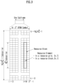
- FIG. 3 illustrates a resource grid in a wireless communication system to which the present disclosure may be applied.
- a resource grid is configured with N RB ⁇ N sc RB subcarriers in a frequency domain and one subframe is configured with 14 ⁇ 2 ⁇ OFDM symbols, but it is not limited thereto.
- a transmitted signal is described by OFDM symbols of 2 ⁇ N symb ( ⁇ ) and one or more resource grids configured with N RB ⁇ N sc RB subcarriers.
- N RB ⁇ ⁇ N RB max, ⁇ The N RB max, ⁇ represents a maximum transmission bandwidth, which may be different between an uplink and a downlink as well as between numerologies.
- one resource grid may be configured per ⁇ and antenna port p.
- Each element of a resource grid for ⁇ and an antenna port p is referred to as a resource element and is uniquely identified by an index pair (k,l').
- an index pair (k,l) is used.
- l 0,..., N symb ⁇ -1.
- a resource element (k,l') for ⁇ and an antenna port p corresponds to a complex value, a k,l' (p, ⁇ ) .
- indexes p and ⁇ may be dropped, whereupon a complex value may be a k,l' (p) or a k,l' .
- Point A plays a role as a common reference point of a resource block grid and is obtained as follows.
- Common resource blocks are numbered from 0 to the top in a frequency domain for a subcarrier spacing configuration ⁇ .
- the center of subcarrier 0 of common resource block 0 for a subcarrier spacing configuration ⁇ is identical to 'point A'.
- a relationship between a common resource block number n CRB ⁇ and a resource element (k,l) for a subcarrier spacing configuration ⁇ in a frequency domain is given as in the following Equation 1.
- n CRB ⁇ ⁇ k N sc RB ⁇
- Physical resource blocks are numbered from 0 to N BWP,i size, ⁇ -1 in a bandwidth part (BWP) and i is a number of a BWP.
- a relationship between a physical resource block n PRB and a common resource block n CRB in BWP i is given by the following Equation 2.
- N BWP,i start, ⁇ is a common resource block that a BWP starts relatively to common resource block 0.
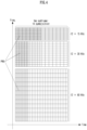
- FIG. 4 illustrates a physical resource block in a wireless communication system to which the present disclosure may be applied.
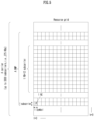
- FIG. 5 illustrates a slot structure in a wireless communication system to which the present disclosure may be applied.
- a slot includes a plurality of symbols in a time domain. For example, for a normal CP, one slot includes 7 symbols, but for an extended CP, one slot includes 6 symbols.
- a carrier includes a plurality of subcarriers in a frequency domain.
- An RB Resource Block
- a BWP(Bandwidth Part) is defined as a plurality of consecutive (physical) resource blocks in a frequency domain and may correspond to one numerology (e.g., an SCS, a CP length, etc.).
- a carrier may include a maximum N (e.g., 5) BWPs.
- a data communication may be performed through an activated BWP and only one BWP may be activated for one terminal.
- each element is referred to as a resource element (RE) and one complex symbol may be mapped.
- RE resource element
- a terminal operating in such a wideband CC may always operate turning on a radio frequency (FR) chip for the whole CC, terminal battery consumption may increase.
- FR radio frequency
- a different numerology e.g., a subcarrier spacing, etc.
- each terminal may have a different capability for the maximum bandwidth.
- a base station may indicate a terminal to operate only in a partial bandwidth, not in a full bandwidth of a wideband CC, and a corresponding partial bandwidth is defined as a bandwidth part (BWP) for convenience.
- a BWP may be configured with consecutive RBs on a frequency axis and may correspond to one numerology (e.g., a subcarrier spacing, a CP length, a slot/a mini-slot duration).
- a base station may configure a plurality of BWPs even in one CC configured to a terminal. For example, a BWP occupying a relatively small frequency domain may be configured in a PDCCH monitoring slot, and a PDSCH indicated by a PDCCH may be scheduled in a greater BWP.
- some terminals may be configured with other BWP for load balancing.
- some middle spectrums of a full bandwidth may be excluded and BWPs on both edges may be configured in the same slot.
- a base station may configure at least one DL/UL BWP to a terminal associated with a wideband CC.
- a base station may activate at least one DL/UL BWP of configured DL/UL BWP(s) at a specific time (by L1 signaling or MAC CE(Control Element) or RRC signaling, etc.).
- a base station may indicate switching to other configured DL/UL BWP (by L1 signaling or MAC CE or RRC signaling, etc.).
- a timer when a timer value is expired, it may be switched to a determined DL/UL BWP.
- an activated DL/UL BWP is defined as an active DL/UL BWP.
- a configuration on a DL/UL BWP may not be received when a terminal performs an initial access procedure or before a RRC connection is set up, so a DL/UL BWP which is assumed by a terminal under these situations is defined as an initial active DL/UL BWP.
- FIG. 6 illustrates physical channels used in a wireless communication system to which the present disclosure may be applied and a general signal transmission and reception method using them.
- a terminal receives information through a downlink from a base station and transmits information through an uplink to a base station.
- Information transmitted and received by a base station and a terminal includes data and a variety of control information and a variety of physical channels exist according to a type/a usage of information transmitted and received by them.
- a terminal When a terminal is turned on or newly enters a cell, it performs an initial cell search including synchronization with a base station or the like (S601).
- a terminal may synchronize with a base station by receiving a primary synchronization signal (PSS) and a secondary synchronization signal (SSS) from a base station and obtain information such as a cell identifier (ID), etc.
- PSS primary synchronization signal
- SSS secondary synchronization signal
- ID cell identifier
- a terminal may obtain broadcasting information in a cell by receiving a physical broadcast channel (PBCH) from a base station.
- PBCH physical broadcast channel
- a terminal may check out a downlink channel state by receiving a downlink reference signal (DL RS) at an initial cell search stage.
- DL RS downlink reference signal
- a terminal which completed an initial cell search may obtain more detailed system information by receiving a physical downlink control channel (PDCCH) and a physical downlink shared channel (PDSCH) according to information carried in the PDCCH (S602).
- PDCCH physical downlink control channel
- PDSCH physical downlink shared channel
- a terminal when a terminal accesses to a base station for the first time or does not have a radio resource for signal transmission, it may perform a random access (RACH) procedure to a base station (S603 to S606).
- RACH random access
- a terminal may transmit a specific sequence as a preamble through a physical random access channel (PRACH) (S603 and S605) and may receive a response message for a preamble through a PDCCH and a corresponding PDSCH (S604 and S606) .
- PRACH physical random access channel
- a contention based RACH may additionally perform a contention resolution procedure.
- a terminal which performed the above-described procedure subsequently may perform PDCCH/PDSCH reception (S607) and PUSCH(Physical Uplink Shared Channel)/PUCCH(physical uplink control channel) transmission (S608) as a general uplink/downlink signal transmission procedure.
- a terminal receives downlink control information (DCI) through a PDCCH.
- DCI includes control information such as resource allocation information for a terminal and a format varies depending on its purpose of use.
- control information which is transmitted by a terminal to a base station through an uplink or is received by a terminal from a base station includes a downlink/uplink ACK/NACK(Acknowledgement/Non-Acknowledgement) signal, a CQI(Channel Quality Indicator), a PMI(Precoding Matrix Indicator), a RI(Rank Indicator), etc.
- a terminal may transmit control information of the above-described CQI/PMI/RI, etc. through a PUSCH and/or a PUCCH.
- Table 5 represents an example of a DCI format in an NR system.
- DCI Format Use 0_0 Scheduling of a PUSCH in one cell 0_1 Scheduling of one or multiple PUSCHs in one cell, or indication of cell group downlink feedback information to a UE 0_2 Scheduling of a PUSCH in one cell 1_0 Scheduling of a PDSCH in one DL cell 1_1 Scheduling of a PDSCH in one cell 1_2 Scheduling of a PDSCH in one cell
- DCI formats 0_0, 0_1 and 0_2 may include resource information (e.g., UL/SUL(Supplementary UL), frequency resource allocation, time resource allocation, frequency hopping, etc.), information related to a transport block(TB) (e.g., MCS(Modulation Coding and Scheme), a NDI(New Data Indicator), a RV(Redundancy Version), etc.), information related to a HARQ(Hybrid - Automatic Repeat and request) (e.g., a process number, a DAI(Downlink Assignment Index), PDSCH-HARQ feedback timing, etc.), information related to multiple antennas
- resource information e.g., UL/SUL(Supplementary UL), frequency resource allocation, time resource allocation, frequency hopping, etc.
- a transport block(TB) e.g., MCS(Modulation Coding and Scheme), a NDI(New Data Indicator), a RV(Redundancy Version), etc.
- power control information e.g., PUSCH power control, etc.
- scheduling of a PUSCH and control information included in each DCI format may be pre-defined.
- DCI format 0_0 is used for scheduling of a PUSCH in one cell.
- Information included in DCI format 0_0 is CRC (cyclic redundancy check) scrambled by a C-RNTI(Cell Radio Network Temporary Identifier) or a CS-RNTI(Configured Scheduling RNTI) or a MCS-C-RNTI(Modulation Coding Scheme Cell RNTI) and transmitted.
- CRC cyclic redundancy check
- DCI format 0_1 is used to indicate scheduling of one or more PUSCHs or configure grant (CG) downlink feedback information to a terminal in one cell.
- Information included in DCI format 0_1 is CRC scrambled by a C-RNTI or a CS-RNTI or a SP-CSI-RNTI(Semi-Persistent CSI RNTI) or a MCS-C-RNTI and transmitted.
- DCI format 0_2 is used for scheduling of a PUSCH in one cell.
- Information included in DCI format 0_2 is CRC scrambled by a C-RNTI or a CS-RNTI or a SP-CSI-RNTI or a MCS-C-RNTI and transmitted.
- DCI formats 1_0, 1_1 and 1_2 may include resource information (e.g., frequency resource allocation, time resource allocation, VRB(virtual resource block)-PRB(physical resource block) mapping, etc.), information related to a transport block(TB)(e.g., MCS, NDI, RV, etc.), information related to a HARQ (e.g., a process number, DAI, PDSCH-HARQ feedback timing, etc.), information related to multiple antennas (e.g., an antenna port, a TCI(transmission configuration indicator), a SRS(sounding reference signal) request, etc.), information related to a PUCCH (e.g., PUCCH power control, a PUCCH resource indicator, etc.) related to scheduling of a PDSCH and control information included in each DCI format may be pre-defined.
- resource information e.g., frequency resource allocation, time resource allocation, VRB(virtual resource block)-PRB(physical resource block) mapping, etc.
- DCI format 1_0 is used for scheduling of a PDSCH in one DL cell.
- Information included in DCI format 1_0 is CRC scrambled by a C-RNTI or a CS-RNTI or a MCS-C-RNTI and transmitted.
- DCI format 1_1 is used for scheduling of a PDSCH in one cell.
- Information included in DCI format 1_1 is CRC scrambled by a C-RNTI or a CS-RNTI or a MCS-C-RNTI and transmitted.
- DCI format 1_2 is used for scheduling of a PDSCH in one cell.
- Information included in DCI format 1_2 is CRC scrambled by a C-RNTI or a CS-RNTI or a MCS-C-RNTI and transmitted.
- An antenna port is defined so that a channel where a symbol in an antenna port is transmitted can be inferred from a channel where other symbol in the same antenna port is transmitted.
- a property of a channel where a symbol in one antenna port is carried may be inferred from a channel where a symbol in other antenna port is carried, it may be said that 2 antenna ports are in a QC/QCL(quasi co-located or quasi co-location) relationship.
- the channel property includes at least one of delay spread, doppler spread, frequency/doppler shift, average received power, received timing/average delay, or a spatial RX parameter.
- a spatial Rx parameter means a spatial (Rx) channel property parameter such as an angle of arrival.
- a terminal may be configured at list of up to M TCI-State configurations in a higher layer parameter PDSCH-Config to decode a PDSCH according to a detected PDCCH having intended DCI for a corresponding terminal and a given serving cell.
- the M depends on UE capability.
- Each TCI-State includes a parameter for configuring a quasi co-location relationship between ports of one or two DL reference signals and a DM-RS of a PDSCH.
- a quasi co-location relationship is configured by a higher layer parameter qcl-Type1 for a first DL RS and qcl-Type2 for a second DL RS (if configured).
- a QCL type is not the same regardless of whether a reference is a same DL RS or a different DL RS.
- a quasi co-location type corresponding to each DL RS is given by a higher layer parameter qcl-Type of QCL-Info and may take one of the following values.
- a target antenna port is a specific NZP CSI-RS
- a terminal received such indication/configuration may receive a corresponding NZP CSI-RS by using a doppler, delay value measured in a QCL-TypeA TRS and apply a Rx beam used for receiving QCL-TypeD SSB to reception of a corresponding NZP CSI-RS.
- UE may receive an activation command by MAC CE signaling used to map up to 8 TCI states to a codepoint of a DCI field 'Transmission Configuration Indication'.
- a coordinated multi point (CoMP) scheme refers to a scheme in which a plurality of base stations effectively control interference by exchanging (e.g., using an X2 interface) or utilizing channel information (e.g., RI/CQI/PMI/LI(layer indicator), etc.) fed back by a terminal and cooperatively transmitting to a terminal.
- a CoMP may be classified into joint transmission(JT), coordinated Scheduling(CS), coordinated Beamforming(CB), dynamic Point Selection(DPS), dynamic Point Blocking(DPB), etc.
- M-TRP transmission schemes that M TRPs transmit data to one terminal may be largely classified into i) eMBB M-TRP transmission, a scheme for improving a transfer rate, and ii) URLLC M-TRP transmission, a scheme for increasing a reception success rate and reducing latency.
- M-TRP transmission schemes may be classified into i) M-TRP transmission based on M-DCI(multiple DCI) that each TRP transmits different DCIs and ii) M-TRP transmission based on S-DCI(single DCI) that one TRP transmits DCI.
- M-DCI based M-TRP transmission all scheduling information on data transmitted by M TRPs should be delivered to a terminal through one DCI, it may be used in an environment of an ideal BackHaul (ideal BH) where dynamic cooperation between two TRPs is possible.
- scheme 3/4 is under discussion for standardization.
- scheme 4 means a scheme in which one TRP transmits a transport block(TB) in one slot and it has an effect to improve a probability of data reception through the same TB received from multiple TRPs in multiple slots.
- scheme 3 means a scheme in which one TRP transmits a TB through consecutive number of OFDM symbols (i.e., a symbol group) and TRPs may be configured to transmit the same TB through a different symbol group in one slot.
- UE may recognize PUSCH (or PUCCH) scheduled by DCI received in different control resource sets(CORESETs)(or CORESETs belonging to different CORESET groups) as PUSCH (or PUCCH) transmitted to different TRPs or may recognize PDSCH (or PDCCH) from different TRPs.
- the below-described method for UL transmission e.g., PUSCH/PUCCH
- PUSCH/PUCCH PUSCH/PUCCH
- an MTRP-URLLC may mean that the same TB (Transport Block) is transmitted using different layers/time/frequencies of M-TRPs.
- a UE configured with an MTRP-URLLC transmission method may be indicated with multiple TCI state(s) by DCI, and it may be assumed that data received using a QCL RS of each TCI state is the same TB.
- an MTRP-eMBB may mean that different TBs are transmitted using different layers/time/frequencies by M-TRPs.
- a UE configured with an MTRP-eMBB transmission method is indicated by several TCI state(s) by DCI, and it may be assumed that data received using a QCL RS of each TCI state are different TBs.
- a UE separates and uses an RNTI configured for an MTRP-URLLC purpose and an RNTI configured for an MTRP-eMBB purpose
- a CORESET group ID described/mentioned in the present disclosure may mean an index/identification information (e.g., an ID, etc.) for distinguishing a CORESET for each TRP/panel.
- a CORESET group may be a group/union of CORESET distinguished by an index/identification information (e.g., an ID)/the CORESET group ID, etc. for distinguishing a CORESET for each TRP/panel.
- a CORESET group ID may be specific index information defined in a CORESET configuration.
- a CORESET group may be configured/indicated/defined by an index defined in a CORESET configuration for each CORESET.
- a CORESET group ID may mean an index/identification information/an indicator, etc. for distinguishment/identification between CORESETs configured/associated with each TRP/panel.
- a CORESET group ID described/mentioned in the present disclosure may be expressed by being substituted with a specific index/specific identification information/a specific indicator for distinguishment/identification between CORESETs configured/associated with each TRP/panel.
- the CORESET group ID i.e., a specific index/specific identification information/a specific indicator for distinguishment/identification between CORESETs configured/associated with each TRP/panel may be configured/indicated to a terminal through higher layer signaling (e.g., RRC signaling)/L2 signaling (e.g., MAC-CE)/L1 signaling (e.g., DCI), etc.
- RRC signaling e.g., RRC signaling
- L2 signaling e.g., MAC-CE
- L1 signaling e.g., DCI
- uplink control information e.g., CSI, HARQ-A/N(ACK/NACK), SR(scheduling request)
- uplink physical channel resources e.g., PUCCH/PRACH/SRS resources
- HARQ A/N(process/retransmission) for PDSCH/PUSCH, etc. scheduled per each TRP/panel may be managed per corresponding CORESET group (i.e., per TRP/panel belonging to the same CORESET group).
- a higher layer parameter ControlResourceSet information element is used to configure a time/frequency control resource set (CORESET).
- the control resource set may be related to detection and reception of downlink control information.
- the ControlResourceSet IE may include a CORESET-related ID (e.g., controlResourceSetID) / an index of a CORESET pool for a CORESET (e.g., CORESETPoolIndex) / a time/frequency resource configuration of a CORESET / TCI information related to a CORESET, etc.
- an index of a CORESET pool (e.g., CORESETPoolIndex) may be set to 0 or 1.
- a CORESET group may correspond to a CORESET pool
- a CORESET group ID may correspond to a CORESET pool index (e.g., CORESETPoolIndex) .
- NCJT Non-coherent joint transmission
- TP transmission points
- DMRS Demodulation Multiplexing Reference Signal
- a TP delivers data scheduling information through DCI to a terminal receiving NCJT.
- a scheme in which each TP participating in NCJT delivers scheduling information on data transmitted by itself through DCI is referred to as 'multi DCI based NCJT'.
- UE receives N DCI and N PDSCHs from N TPs.
- a scheme in which one representative TP delivers scheduling information on data transmitted by itself and data transmitted by a different TP (i.e., a TP participating in NCJT) through one DCI is referred to as 'single DCI based NCJT'.
- N TPs transmit one PDSCH, but each TP transmits only some layers of multiple layers included in one PDSCH. For example, when 4-layer data is transmitted, TP 1 may transmit 2 layers and TP 2 may transmit 2 remaining layers to UE.
- NCJT partially overlapped NCJT
- NCJT may be classified into fully overlapped NCJT that time frequency resources transmitted by each TP are fully overlapped and partially overlapped NCJT that only some time frequency resources are overlapped.
- data of both of TP 1 and TP 2 are transmitted in some time frequency resources and data of only one TP of TP 1 or TP 2 is transmitted in remaining time frequency resources.
- FIG. 7 illustrates a method of multiple TRPs transmission in a wireless communication system to which the present disclosure may be applied.
- a layer group may mean a predetermined layer set including one or more layers.
- the amount of transmitted resources increases due to the number of a plurality of layers and thereby a robust channel coding with a low coding rate may be used for a TB, and additionally, because a plurality of TRPs have different channels, it may be expected to improve reliability of a received signal based on a diversity gain.
- FIG. 7(b) an example that different CWs are transmitted through layer groups corresponding to different TRPs is shown.
- a TB corresponding to CW #1 and CW #2 in the drawing is identical to each other.
- CW #1 and CW #2 mean that the same TB is respectively transformed through channel coding, etc. into different CWs by different TRPs. Accordingly, it may be considered as an example that the same TB is repetitively transmitted.
- FIG. 7(b) it may have a disadvantage that a code rate corresponding to a TB is higher compared to FIG. 7 (a) .
- it has an advantage that it may adjust a code rate by indicating a different RV (redundancy version) value or may adjust a modulation order of each CW for encoded bits generated from the same TB according to a channel environment.
- RV redundancy version
- probability of data reception of a terminal may be improved as the same TB is repetitively transmitted through a different layer group and each layer group is transmitted by a different TRP/panel. It is referred to as a SDM (Spatial Division Multiplexing) based M-TRP URLLC transmission method. Layers belonging to different layer groups are respectively transmitted through DMRS ports belonging to different DMRS CDM groups.
- the above-described contents related to multiple TRPs are described based on an SDM (spatial division multiplexing) method using different layers, but it may be naturally extended and applied to a FDM (frequency division multiplexing) method based on a different frequency domain resource (e.g., RB/PRB (set), etc.) and/or a TDM (time division multiplexing) method based on a different time domain resource (e.g., a slot, a symbol, a sub-symbol, etc.).
- FDM frequency division multiplexing
- a different frequency domain resource e.g., RB/PRB (set), etc.
- TDM time division multiplexing
- a TCI state is used by a base station to configure/indicate a reception beam (i.e. spatial Rx parameter) to be used when a terminal receives a PDCCH and a PDSCH (i.e. when receiving a DMRS of a PDCCH and a PDSCH) by utilizing the QCL (Quasi Co-Located) concept introduced in Rel-15 NR.
- a reception beam i.e. spatial Rx parameter
- a DL reference signal (e.g., SS/PBCH block resource indicator (SSB-RI), CRI (periodic (P) / semi-persistent (SP) / aperiodic (AP))) can be configured/updated as a reference RS or a source RS of a QCL Type-D component through a corresponding TCI state.
- SSB-RI SS/PBCH block resource indicator
- CRI periodic (P) / semi-persistent (SP) / aperiodic (AP)
- SSB-RI SS/PBCH block resource indicator
- CRI periodic (P) / semi-persistent (SP) / aperiodic (AP)
- P periodic
- SP semi-persistent
- AP aperiodic
- spatial relationship information can be used by a base station to configure/indicate a transmission beam to be used when a terminal transmits a UL channel (e.g., PUSCH or PUCCH or SRS).
- a base station may configure/update a DL reference signal (i.e., SSB-RI, CRI(P/SP/AP)) or an SRS (i.e., SRS resource) as a reference RS for a target UL channel and/or a target RS through RRC configuration and/or MAC control element (CE) activation.
- a DL reference signal i.e., SSB-RI, CRI(P/SP/AP)
- SRS i.e., SRS resource
- a UL transmission beam (i.e., spatial Tx parameter) used when a terminal transmits a PUCCH and an SRS can be configured/indicated.
- a transmission beam configured/updated/indicated by a base station and used for SRS transmission is indicated as a transmission beam for a PUSCH through an SRS resource indicator (SRI) field of UL grant DCI and can be used as a PUSCH transmission beam of the terminal accordingly.
- a TCI state configuration is used to configure/indicate a reception beam for a target DL RS/channel.
- a target DL RS/channel is a CSI-RS
- a terminal reception beam can be configured by setting a QCL type-D RS at an RRC/MAC CE level (signaling) (via configuring a TCI state ID (identifier) within a TCI state pool).
- a target DL RS/channel is a PDCCH
- a terminal reception beam can be configuring by setting up to 64 TCI state IDs in a specific CORESET and then indicating a specific TCI state ID through a MAC CE.
- a reception beam of a corresponding CORESET can be updated through the same MAC CE message.
- a PDSCH reception beam by connecting/associating up to 8 TCI state IDs (within a pool of a maximum of 128 TCI states) to a TCI state field of DL DCI through a MAC CE, a PDSCH reception beam can be indicated through a TCI indication during DL scheduling, a PDSCH reception beam can be updated by updating a TCI state ID connected/associated to the TCI state field through the same MAC CE message.
- an operation between a base station and a terminal has been improved to enable simultaneous/single TCI state ID activation on multiple component carriers (CCs) (or BWP) for a PDCCH and a PDSCH through a MAC CE message.
- CCs component carriers
- BWP component carriers
- a transmission beam can be configured by connecting/associating PUCCH-SpatialRelationInfoId through a MAC CE message for each PUCCH resource to configure/indicate a transmission beam of a PUCCH. Additionally, a MAC level update for PUCCH-SpatialRelationInfo is possible through the same MAC CE message.
- the SRS-SpatialRelationInfo of SRS resources in the semi-persistent SRS resource set can be updated through a MAC CE message that activates transmission of an SRS.
- an operation between a base station and a terminal has been improved to enable updating of SRS-SpatialRelationInfo for SRS resources in a corresponding aperiodic SRS resource set through a MAC CE message.
- an operation between a base station and a terminal has been improved to enable simultaneous updating of a spatial relation reference RS (RS) in multiple CC (BWP) for an SP-SRS and an AP-SRS through a MAC CE message.
- RS spatial relation reference RS
- BWP multiple CC
- an operation between a base station and a terminal has been improved to enable simultaneous spatial relationship updating for PUSCH resources in a corresponding PUCCH resource group.
- higher layer signaling such as an RRC and a MAC CE is mainly used for a beam indication/update operation for reception/transmission between a base station and a terminal, and a DCI-based beam indication operation was supported for some channels/RS (e.g., PDSCH, PUSCH), etc.
- a dynamic beam update operation using a joint DL/UL TCI state and a separate DL/UL TCI state will be introduced.
- Standardization was carried out for a terminal common beam update operation in which a base station uses DCI to perform an indication/update with one common beam for a plurality of specific channel/RS combinations of a terminal.
- a target channel/RS of common beam update in the case of DL, a UE-dedicated CORESET and UE-dedicated reception on a PDSCH can be configured.
- a dedicated PUCCH can be configured as a target channel/RS of common beam update.
- an AP CSI-RS and an SRS for tracking/beam management (BM) can be configured as a target channel/RS.
- the ACK/NAK of the PDSCH scheduled by the DCI carrying the beam indication can be used as an ACK also for the DCI.
- UE does not expect UL TCI to provide a reference for determining common UL TX spatial filter(s), if UL TCI is supported for FR1.
- a NACK can be reported.
- a location for the ACK information in the HARQ-ACK codebook is determined based on a virtual PDSCH indicated by the TDRA (time domain resource allocation) field in the beam indication DCI, based on the time domain allocation list configured for PDSCH.
- TDRA time domain resource allocation
- a location for the ACK information in the HARQ-ACK codebook is determined according to the same rule for SPS release.
- the ACK is reported in a PUCCH k slots after the end of the PDCCH reception where k is indicated by the PDSCH-to-HARQ_feedback timing indicator field in the DCI format, or provided dl-DataToUL-ACK or dl-DataToUL-ACK-ForDCI-Format1-2-r16 if the PDSCH-to-HARQ_feedback timing indicator field is not present in the DCI.
- Identifier for DCI formats Carrier indicator, Bandwidth part indicator, TDRA, Downlink assignment index (if configured), TPC (transit power control) command for scheduled PUCCH, PUCCH resource indicator, PDSCH-to-HARQ_feedback timing indicator (if present)
- configuration of joint TCI or separate DL/UL TCI is based on RRC signaling.
- Rel-17 MAC-CE-based and/or DCI-based beam indication (at least using DCI formats 1_1/1_2 with and without DL assignment including the associated MAC-CE-based TCI state activation)
- the following DL RSs can share the same indicated Rel-17 TCI state as UE-dedicated reception on PDSCH and for UE-dedicated reception on all or subset of CORESETs in a CC.
- the following DL RSs can share the same indicated Rel-17 TCI state as UE-dedicated reception on PDSCH and for UE-dedicated reception on all or subset of CORESETs in a CC:
- Rel.17 unified TCI framework for any DL RS that does not share the same indicated Rel-17 TCI state (s) as UE-dedicated reception on PDSCH and for UE-dedicated reception on all or subset of CORESETs in a CC, but can be configured as a target DL RS of a Rel-17 DL TCI (hence the Rel-17 DL TCI state pool), Rel-17 mechanism(s) which reuse the Rel-15/16 TCI state update signaling/configuration design(s) are used to update/configure such DL RS(s) with Rel-17 TCI state(s).
- the source RS in the Rel-17 TCI state that provides QCL-TypeA or QCL-TypeB shall be in the same CC/BWP as the target channel or RS.
- Rel-17 unified TCI for Rel-17 unified TCI, for DL or UL channels/signals that can share the same indicated Rel-17 TCI state as UE-dedicated reception on PDSCH/PDCCH or dynamic-grant/configured-grant based PUSCH, all of dedicated PUCCH resources (via Rel-17 MAC-CE/DCI TCI state update):
- any SRS resource or resource set that is a valid target signal of a Rel-15/16 spatial relation based on the Rel-15/16 spatial relation rules (on source-target relations) can be configured as a target signal of a Rel-17 UL or, if applicable, joint TCI (hence the Rel-17 UL or, if applicable, joint TCI state pool).
- the UE is not expected to be configured with Rel-15/Rel-16 TCI/SpatialRelationInfo if the UE is configured with Rel-17 TCI in any CC in a band.
- a UE-dedicated CORESET and UE-dedicated reception on a PDSCH can be configured.
- a UE may be provided with two CORESET pool index (e.g., coresetPoolIndex) values 0 and 1 for a first CORESET and a second CORESET, respectively.
- a UE may not be provided with a CORESET pool index (e.g., coresetPoolIndex) value for a first CORESET(s) and may be provided with 1 as a CORESET pool index value for a second CORESET (s).
- a UE can receive DCI from a specific TRP in CORESET(s) belonging to each pool.
- ⁇ /' may be interpreted as 'and', 'or', or 'and/or' depending on the context.
- a transmission panel/beam to be used when transmitting a PUCCH/PUSCH can be interpreted/applied as a transmission beam to be used when transmitting a DMRS of a PUCCH/PUSCH.
- applying a transmission beam when transmitting a PUCCH/PUSCH/PRACH/SRS, etc. means applying a spatial transmission parameter/spatial domain transmission filter/spatial transmission filter (spatial Tx parameter / spatial domain Tx filter / spatial Tx filter) for transmission of a corresponding PUCCH/PUSCH/PRACH/SRS.
- applying a reception beam when receiving a CORESET/PDCCH/PDSCH/CSI-RS, etc. means applying a spatial reception parameter (spatial Rx parameter) for reception of a CORESET/PDCCH/PDSCH/CSI-RS.
- Embodiment 1 In a BWP in which a UE's CORESET pool index (e.g., CORESETPoolIndex) is configured (i.e., a BWP in which a plurality of CORESET pools are configure), a method in which a UE updates a CORESET beam when performing a common beam update using a joint DL/UL TCI state and/or a separate DL/UL TCI state (e.g., DL only TCI state or UL only TCI state) of a base station.
- CORESETPoolIndex i.e., a BWP in which a plurality of CORESET pools are configure
- Embodiment 1-1 When a common beam update (or indication) is performed in the corresponding (active) BWP (i.e., a BWP in which multiple CORESET pools are configured), a UE (UE-dedicated) does not perform updates of all CORESET beams in a corresponding BWP even though a CORESET is a target channel/RS of common beam update. That is, a UE can override a base station's DCI-based common beam update indication for all CORESETs in a corresponding BWP (i.e., excluding a common beam target channel/RS). Through this operation, a UE can maintain two CORESET pool configuration within a corresponding BWP. Therefore, a UE can smoothly receive DCI from each TRP by referring to a QCL-type D RS (of TCI state) configured/activated/corresponding to each CORESET in each CORESET pool.
- a QCL-type D RS of TCI state
- the above operation may mean that when a UE receives a common beam update (or indication) for a corresponding BWP, a beam update is not performed only for a CORESET. Therefore, a UE can perform a beam update operation according to a common beam update (or indication) for target channels/RSs other than a CORESET.
- Embodiment 1-1 can also be used for "common TCI state ID update and activation for CA case" operations (e.g., among the above agreements, i) one source RS across CCs with operation determined from a common TCI state ID indicated to provide a QCL Type-D indication and determine a UL TX spatial filter for a set of configured CCs (i.e., operation of common TCI state pool for CCs), and ii) one source RS per CC can be determined from a common TCI state ID indicated to provide a QCL Type-D indication and determine a UL TX spatial filter for a set of configured CCs, a CC-specific source RS is additionally associated with the same QCL-TypeD RS (i.e., operation of TCI state pool per CC)).
- common TCI state ID update and activation for CA case operations (e.g., among the above agreements, i) one source RS across CCs with operation determined from a common TCI state ID indicated to provide a
- a UE may not perform common TCI state ID update and activation operations for the CA case for all CORESETs in a corresponding CC/BWP. And/or, in the set of the configured CCs, the corresponding CC/BWP may be excluded from a TCI state indication of the common TCI state ID update and activation operations.
- Embodiment 1-2 When a common beam update is performed in the corresponding (active) BWP (i.e., a BWP in which multiple CORESET pools are configured), a UE may perform a common beam update only for (first) CORESET(s) for which a CORESET pool index (e.g. CORESETPoolIndex) is set to 0 or for which no CORESET pool index (e.g. CORESETPoolIndex) is provided, and may not perform a beam update for the remaining (second) CORESET(s). Or, conversely, a UE may perform a common beam update on (second) CORESET(s) without performing a beam update on (first) CORESET(s). Alternatively, configuration/switching may be performed by a base station for the above two operations.
- a CORESET pool index e.g. CORESETPoolIndex
- no CORESET pool index e.g. CORESETPoolIndex
- a UE when receiving DCI from a primary TRP in the first (or second) CORESET(s) within a corresponding BWP of a UE, a UE can perform one beam operation by performing a common beam update operation only on the CORESET(s) corresponding to the primary TRP.
- Embodiment 1-2 can also be utilized in the "update and activate common TCI state ID for CA case" operation.
- a UE may perform a common beam update only for CORESET(s) within a CC that is predetermined (e.g. CC with lowest/highest cell ID) or configured by a base station among multiple CCs for which a CA is configured.
- Embodiment 2 When M, the number of DL TCIs and/or N, the number of UL TCIs for a common beam operation of a UE, is greater than 1, M and/or N may correspond to the number of TRPs for a base station and/or the number of Rx/Tx beams/panels of the UE. Specifically, M, the number of DL TCIs, may correspond to M TRPs (for DL transmission) for a base station or M Rx beams/panels of a terminal. Additionally, N, the number of UL TCIs, may correspond to M TRPs (for UL reception) for a base station or M Tx beams/panels of a terminal. That is, when there are multiple M/Ns, multiple different TRPs for a base station and M/N common beam references for a terminal to receive/transmit through multiple different beams/panels can be configured/indicated.
- each of M source reference signals (or 2M, if qcl_Type2 is configured in addition to qcl_Type1) in M DL TCIs may provide QCL information for at least one of M beam pair links for UE-dedicated reception in a PDSCH and/or on a subset of CORESETs in a CC.
- each of N source reference signals of N UL TCIs can provide a reference for determining a UL TX spatial filter for at least one of N beam pair links associated with a dynamic-grant/configured-grant based PUSCH and/or subset of dedicated PUCCH resources within a CC.
- a joint DL/UL TCI may refer to at least a common source reference RS used to determine both DL QCL information and UL TX spatial filter. Additionally, when M>1 and N>1, M DL TCI and N UL TCI can be configured separately.
- Embodiment 2-1 A base station can configure/update a target channel/RS for applying M/N (DL/UL) TCIs of a UE (in common beam operation) through higher layer signaling (e.g. RRC/MAC CE signaling).
- M/N DL/UL
- MAC CE Radio Resource Control
- a target channel/RS may include at least one (i.e., all or part) of an (M-TRP repeat) PDCCH, a subset of CORESETs (e.g. CORESET(s) with a specific CORESET pool index (CORESETPoolIndex)), an (M-TRP repeat) PDSCH, an AP CSI-RS for BM or CSI, an (M-TRP repeat) PUCCH, a subset of dedicated PUCCH resources (e.g., all or some PUCCH groups), an (M-TRP repeat) PUSCH, or SRS.
- an (M-TRP repeat) PDCCH a subset of CORESETs (e.g. CORESET(s) with a specific CORESET pool index (CORESETPoolIndex)), an (M-TRP repeat) PDSCH, an AP CSI-RS for BM or CSI, an (M-TRP repeat) PUCCH, a subset of dedicated PUCCH
- a first TCI may correspond to a first transmission occasion (TO) group of a PDCCH/PDSCH/CSI-RS/PUCCH/PUSCH/SRS, a first CORESET(s) with a CORESET pool index (e.g. CORESETPoolIndex) value of 0 and/or a first PUCCH group.
- a second TCI may correspond to a second TO group of a PDCCH/PDSCH/CSI-RS/PUCCH/PUSCH/SRS, a second CORESET(s) with a CORESET pool index (e.g., CORESETPoolIndex) value of 1, and/or a second PUCCH group.
- a base station can clearly configure/indicate a terminal to which M/N TCIs are, respectively, applied to some target channels/RSs of each specific channels/RSs.
- Embodiment 2-3 M/N TCI states for configuring/indicating (with plural) M/N common reference RS (related to joint TCI) and/or separate reference RS (related to separate TCI) can be associated/mapped/connected to each codepoint in a TCI state field of DL/UL grant DCI. Additionally, a base station can indicate a UE to apply a common beam for M/N reception/transmission by indicating the corresponding codepoint to the UE through the DCI. Through this operation, unlike Rel-17, a base station can dynamically indicate multiple M/N TCIs and operate multiple (M/N) common beam references for multi-TRP/panel.
- codepoints with one DL/UL TCI i.e., associated/mapped/connected
- codepoints with multiple DL/UL TCIs i.e., associated/mapped/connected
- a codepoint with one DL/UL TCI i.e., associated/mapped/connected
- a base station a UE understands/considers that a common beam operation of Rel-17 is being performed and can perform a beam update operation.
- a UE understands/considers that multiple TCIs (i.e., M/N TCIs) are applied to a (preconfigured) target channel/RS and can perform a beam update operation.
- one TCI update and multiple TCI updates can be dynamically switched through a corresponding field.
- one TCI update is indicated, at least one method among several methods related to Embodiment 1 can be used for two CORESET pools.
- a UE may update (with the same TCI) all CORESET(s) related to/same as a CORESET pool index (e.g., CORESETPoolIndex) of a CORESET in which DCI for a TCI update is transmitted, and may not perform updates on CORESET(s) for which a different CORESET pool index (e.g., CORESETPoolIndex) has been configured.
- CORESETPoolIndex e.g., CORESETPoolIndex
- the update can be performed only on a PUCCH resource group (i.e. all PUCCH resources within that PUCCH resource group) associated with DCI for a corresponding TCI update (with the same TCI).
- a PUCCH resource group associated with DCI for a corresponding TCI update may be, for example, a PUCCH resource group to which a PUCCH resource corresponding to a PUCCH resource indicator (PRI) designated/indicated by corresponding DCI belongs.
- PRI PUCCH resource indicator
- a PUCCH resource group associated with DCI for a corresponding TCI update may be a PUCCH resource group to which a PUCCH resource to which a (aperiodic/semi-persistent) CSI report that is triggered/activated/deactivated by corresponding DCI is transmitted belongs. For example, it may be determined for which PUCCH resource group a TCI state will be updated depending on a CORESET pool index (e.g., CORESETPoolIndex) on which DCI scheduling an active MAC-CE (i.e., via PDSCH) for semi persistent (SP)-CSI reporting on a PUCCH is transmitted.
- CORESET pool index e.g., CORESETPoolIndex
- a PUCCH resource group with the lowest index is determined, and in the case of the highest CORESET pool index, a mapping relationship in ascending order in which a PUCCH resource group with the highest index is determined can be considered.
- Embodiment 1 Embodiment 1-1/1-2
- Embodiment 2 Embodiment 2-1/2-2/2-3
- only one may be performed between a base station and a terminal, or a plurality of operations may be performed in combination.
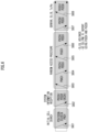
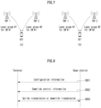
- FIG. 8 illustrates a signaling procedure between a network and a terminal for a wireless signal transmission and reception method according to an embodiment of the present disclosure.
- FIG. 8 illustrates signaling between a network (e.g., TRP 1, TRP 2) and a UE in a situation of multi-TRPs (multiple TRPs) (i.e., M-TRPs, or multiple cells, hereinafter, all TRPs may be replaced with a cell) that methods proposed in the present disclosure (e.g., any one or a combination of one or more in Embodiment 1, Embodiment 2, and the detailed examples for Embodiments 1 and 2) may be applied.
- a UE/a network is just an example, and may be applied by being substituted with a variety of devices.
- FIG. 8 is just for convenience of a description, and does not limit a scope of the present disclosure.
- some step(s) illustrated in FIG. 8 may be omitted depending on circumstances and/or configurations.
- a network may be one base station including a plurality of TRPs or may be one cell including a plurality of TRPs.
- an ideal/a non-ideal backhaul may be configured between TRP 1 and TRP 2 configuring a network.
- the following description is described based on a plurality of TRPs, but it may be equally extended and applied to transmission through a plurality of panels.
- an operation that a terminal receives a signal from TRP1/TRP2 may be interpreted/described (or may be an operation) as an operation that a terminal receives a signal from a network (through/with TRP1/2) and an operation that a terminal transmits a signal to TRP1/TRP2 may be interpreted/described (or may be an operation) as an operation that a terminal transmits a signal to a network (through/with TRP1/TRP2) or may be conversely interpreted/described.
- a UE receives configuration/DCI from a representative TRP (e.g., TRP 1) in an M-TRP situation (or cell, hereinafter all TRPs can be replaced by a cell/panel, or M-TRP can be assumed even when a plurality of CORESETs are configured from one TRP).
- TRP 1 a representative TRP
- M-TRP can be assumed even when a plurality of CORESETs are configured from one TRP.
- the representative TRP may be a TRP for transmitting/transporting a system information block (SIB) / paging / random access (RA) related signal to a UE.
- SIB system information block
- RA random access
- a UE may receive configuration information through/using TRP 1 (and/or TRP 2) from a network (S801).
- the configuration information may include information related to network configuration (e.g., TRP configuration) / information related to M-TRP-based transmission/reception (e.g., resource allocation, etc.).
- the configuration information may be transmitted through higher layer signaling (e.g., RRC signaling, MAC-CE, etc.).
- the configuration information may include configuration information related to the beam indication/update procedure described in the above-mentioned proposed methods (e.g., any one or a combination of one or more in Embodiment 1, Embodiment 2, and the detailed examples for Embodiments 1 and 2) .
- the configuration information may include information for configuring a joint TCI and/or a separate DL/UL TCI.
- the configuration information may include a list of TCI states that provides a reference signal for QCL for a DMRS/downlink signal (e.g., CSI-RS) of a downlink channel (e.g., PDSCH, PDCCH), and/or provides a reference for determining an uplink transmission spatial filter of a DMRS/uplink signal (e.g., SRS) of an uplink channel (e.g., PUSCH, PUCCH).
- a downlink channel may be a concept that includes all downlink channels/signals
- an uplink channel may be a concept that includes all uplink channels/signals.
- the configuration information may include a CORESET configuration.
- a configuration for each CORESET may include a CORESET pool index for a CORESET pool to which the CORESET belongs.
- a UE may receive downlink control information (DCI) from a network through/using TRP 1 (and/or TRP 2) (S802).
- DCI downlink control information
- DCI may be transmitted through a downlink control channel (e.g., PDCCH), and a UE may monitor/receive a downlink control channel (e.g., PDCCH) in one or more CORESETs configured in its BWP and detect/decode DCI.
- a downlink control channel e.g., PDCCH
- PDCCH downlink control channel
- DCI may schedule transmission of a downlink channel (e.g., PDSCH) or an uplink channel (e.g., PUSCH) and may trigger transmission of an uplink signal (e.g., SRS).
- DCI may not include uplink assignment or downlink assignment.
- DCI may include a transmission configuration indication (TCI) field, and a TCI state for a downlink/uplink channel/signal may be indicated by a codepoint in the TCI field.
- TCI transmission configuration indication
- a TCI codepoint may be mapped/corresponding to one TCI state, and/or may be mapped/corresponding to multiple TCI states.
- a UE may perform uplink transmission (i.e., uplink channel (e.g., PUCCH, PUSCH) and/or signal (e.g., SRS)) to a network or receive downlink transmission (i.e., downlink channel (e.g., PDSCH, PDCCH) and/or signal (e.g., CSI-RS)) from a network (S803).
- uplink channel e.g., PUCCH, PUSCH
- signal e.g., SRS
- a UE can perform uplink transmission or receive downlink transmission based on the above-described proposed methods (e.g., any one or a combination of one or more in Embodiment 1, Embodiment 2, and the detailed examples for Embodiments 1 and 2).
- the indicated single TCI state can be applied to both uplink transmission and downlink transmission associated with a CORESET pool index of a CORESET in which the DCI is transmitted. That is, when a UE performs uplink transmission, based on a TCI state indicated by DCI, an RS in the corresponding TCI state can be used as a reference to determine an uplink transmission spatial filter for uplink transmission. In addition, when a UE receives downlink transmission, based on a TCI state indicated by DCI, downlink transmission can be received by assuming a QCL relationship between an RS and downlink transmission in the corresponding TCI state.
- the indicated TCI state may be applied to all PUCCH resources in a PUCCH resource group associated with a CORESET pool index of a CORESET in which the DCI was transmitted.
- the associated PUCCH resource group may mean a PUCCH resource group to which a PUCCH resource indicated by a PUCCH resource indicator (PRI) field in the DCI belongs.
- the associated PUCCH resource group may mean a PUCCH resource group to which a PUCCH resource to which a CSI report triggered by the DCI is transmitted belongs.
- uplink or downlink transmission to which the two TCI states apply may be configured by the network (e.g., through higher layer signaling).
- a first TCI state may be applied to one or more CORESETs having a first CORESET pool index
- a second TCI state may be applied to one or more CORESETs having a second CORESET pool index.
- applying to a CORESET may mean applying to a PDCCH (i.e., DMRS of PDCCH) monitored/received in a corresponding CORESET.
- a first TCI state is applied to a first TO (or first TO group) of uplink or downlink transmission
- a second TCI state may be applied to a second TO (or second TO group) of the uplink or downlink transmission. That is, a TCI state can be applied according to a predetermined rule (e.g., as an index of a TO (or TO group) increases, it is mapped in ascending/descending order of a TCI state index) for each TO (or TO group) or according to configuration by the network.
- a predetermined rule e.g., as an index of a TO (or TO group) increases, it is mapped in ascending/descending order of a TCI state index
- a UE may receive first DCI from a first TRP and second DCI from a second TRP.
- first DCI and second DCI may each include a TCI field, and each TCI field indicates one TCI state, so a total of two TCI states may be indicated to a UE.
- FIG. 9 is a diagram illustrating an operation of a terminal for a method of transmitting and receiving a wireless signal according to an embodiment of the present disclosure.
- FIG. 9 an operation of a UE based on the previously proposed methods (e.g., any one or a combination of one or more in Embodiment 1, Embodiment 2, and the detailed examples for Embodiments 1 and 2) is exemplified.
- the example of FIG. 9 is for convenience of description, and does not limit the scope of the present disclosure. Some step(s) illustrated in FIG. 9 may be omitted depending on circumstances and/or configurations.
- a UE in FIG. 9 is only one example, and may be implemented as the device illustrated in FIG. 11 below.
- the processor 102/202 of FIG. 11 may control to transmit/receive a channel/signal/data/information, etc. using the transceiver 106/206, and may control to store a transmitted or received channel/signal/data/information, etc. may be controlled in the memory 104/204.
- FIG. 9 may be processed by one or more processors 102, 202 of FIG. 11 , and the operations of FIG. 9 may be stored in a memory (e.g., one or more memories 104, 204 of FIG. 11 ) in the form of instructions/programs (e.g., instruction, executable code) for driving at least one processor (e.g., 102 and 202) of FIG. 11 .
- a memory e.g., one or more memories 104, 204 of FIG. 11
- instructions/programs e.g., instruction, executable code
- a UE receives first configuration information including a list of TCI states from a base station (S901).
- a list of TCI states may correspond to a list of TCI states for a joint (or unified) TCI configuration commonly applicable to uplink/downlink transmission, or correspond to a list of TCI states for separate TCI configurations that are individually applicable to uplink or downlink transmission.
- the first configuration information may include a list of TCI states that provides a reference signal for QCL for a DMRS/downlink signal (e.g., CSI-RS) of a downlink channel (e.g., PDSCH, PDCCH), and/or provides a reference for determining an uplink transmission spatial filter of a DMRS/uplink signal (e.g., SRS) of an uplink channel (e.g., PUSCH, PUCCH).
- CSI-RS CSI-RS
- uplink transmission spatial filter of a DMRS/uplink signal e.g., SRS
- the first configuration information may be transmitted by being included in configuration information for a PDSCH (e.g., PDSCH-Config) or may be transmitted by being included in configuration information for a BWP (e.g., BWP).
- a PDSCH e.g., PDSCH-Config
- BWP e.g., BWP
- a UE may receive second configuration information related to a CORESET from a base station (S902).
- the second configuration information related to a CORESET may be transmitted as individual configuration information for each CORESET, and configuration information for each CORESET may include a CORESET pool index for a CORESET pool to which the corresponding CORESET belongs.
- the second configuration information may be transmitted by being included in configuration information for a PDCCH (e.g., PDCCH-Config) or may be transmitted by being included in configuration information for a BWP (e.g., BWP).
- a PDCCH e.g., PDCCH-Config
- BWP e.g., BWP
- a UE receives downlink control information (DCI) from a base station (S903).
- DCI downlink control information
- DCI may be transmitted through a downlink control channel (e.g., PDCCH), and a UE may monitor/receive a downlink control channel (e.g., PDCCH) in one or more CORESETs configured in its BWP and detect/decode DCI.
- a downlink control channel e.g., PDCCH
- PDCCH downlink control channel
- DCI may schedule transmission of a downlink channel (e.g., PDSCH) or an uplink channel (e.g., PUSCH) and may trigger transmission of an uplink signal (e.g., SRS).
- DCI may not include uplink assignment or downlink assignment.
- DCI may include a transmission configuration indication (TCI) field, and a TCI state for a downlink/uplink channel/signal may be indicated by a codepoint in the TCI field.
- TCI transmission configuration indication
- a TCI codepoint may be mapped/corresponding to one TCI state, and/or may be mapped/corresponding to multiple TCI states.
- a UE may perform uplink transmission (i.e., uplink channel (e.g., PUCCH, PUSCH) and/or signal (e.g., SRS)) to a base station or receive downlink transmission (i.e., downlink channel (e.g., PDSCH, PDCCH) and/or signal (e.g., CSI-RS)) from a base station (S904).
- uplink channel e.g., PUCCH, PUSCH
- signal e.g., SRS
- a UE can perform uplink transmission or receive downlink transmission based on the above-described proposed methods (e.g., any one or a combination of one or more in Embodiment 1, Embodiment 2, and the detailed examples for Embodiments 1 and 2).
- the indicated single TCI state can be applied to both uplink transmission and downlink transmission associated with a CORESET pool index of a CORESET in which the DCI is transmitted. That is, when a UE performs uplink transmission, based on a TCI state indicated by DCI, an RS in the corresponding TCI state can be used as a reference to determine an uplink transmission spatial filter for uplink transmission. In addition, when a UE receives downlink transmission, based on a TCI state indicated by DCI, downlink transmission can be received by assuming a QCL relationship between an RS and downlink transmission in the corresponding TCI state.
- the indicated TCI state may be applied to all PUCCH resources in a PUCCH resource group associated with a CORESET pool index of a CORESET in which the DCI was transmitted.
- the associated PUCCH resource group may mean a PUCCH resource group to which a PUCCH resource indicated by a PUCCH resource indicator (PRI) field in the DCI belongs.
- the associated PUCCH resource group may mean a PUCCH resource group to which a PUCCH resource to which a CSI report triggered by the DCI is transmitted belongs.
- uplink or downlink transmission to which the two TCI states apply may be configured by the network (e.g., through higher layer signaling).
- a first TCI state may be applied to one or more CORESETs having a first CORESET pool index
- a second TCI state may be applied to one or more CORESETs having a second CORESET pool index.
- applying to a CORESET may mean applying to a PDCCH (i.e., DMRS of PDCCH) monitored/received in a corresponding CORESET.
- a first TCI state is applied to a first TO (or first TO group) of uplink or downlink transmission
- a second TCI state may be applied to a second TO (or second TO group) of the uplink or downlink transmission. That is, a TCI state can be applied according to a predetermined rule (e.g., as an index of a TO (or TO group) increases, it is mapped in ascending/descending order of a TCI state index) for each TO (or TO group) or according to configuration by the network.
- a predetermined rule e.g., as an index of a TO (or TO group) increases, it is mapped in ascending/descending order of a TCI state index
- a UE may receive first DCI from a first TRP and second DCI from a second TRP.
- first DCI and second DCI may each include a TCI field, and each TCI field indicates one TCI state, so a total of two TCI states may be indicated to a UE.
- FIG. 10 is a diagram illustrating an operation of a base station for a method of transmitting and receiving a wireless signal according to an embodiment of the present disclosure.
- FIG. 10 an operation of a base station based on the previously proposed methods (e.g., any one or a combination of one or more in Embodiment 1, Embodiment 2, and the detailed examples for Embodiments 1 and 2) is exemplified.
- the example of FIG. 10 is for convenience of description, and does not limit the scope of the present disclosure. Some step(s) illustrated in FIG. 10 may be omitted depending on circumstances and/or configurations.
- a base station in FIG. 10 is only one example, and may be implemented as the device illustrated in FIG. 11 below.
- the processor 102/202 of FIG. 11 may control to transmit/receive a channel/signal/data/information, etc. using the transceiver 106/206, and may control to store a transmitted or received channel/signal/data/information, etc. may be controlled in the memory 104/204.
- FIG. 10 may be processed by one or more processors 102, 202 of FIG. 11 , and the operations of FIG. 10 may be stored in a memory (e.g., one or more memories 104, 204 of FIG. 11 ) in the form of instructions/programs (e.g., instruction, executable code) for driving at least one processor (e.g., 102 and 202) of FIG. 11 .
- a memory e.g., one or more memories 104, 204 of FIG. 11
- instructions/programs e.g., instruction, executable code
- a base station transmits first configuration information including a list of TCI states to a UE (S1001).
- a list of TCI states may correspond to a list of TCI states for a joint (or unified) TCI configuration commonly applicable to uplink/downlink transmission, or correspond to a list of TCI states for separate TCI configurations that are individually applicable to uplink or downlink transmission.
- the first configuration information may include a list of TCI states that provides a reference signal for QCL for a DMRS/downlink signal (e.g., CSI-RS) of a downlink channel (e.g., PDSCH, PDCCH), and/or provides a reference for determining an uplink transmission spatial filter of a DMRS/uplink signal (e.g., SRS) of an uplink channel (e.g., PUSCH, PUCCH).
- CSI-RS CSI-RS
- uplink transmission spatial filter of a DMRS/uplink signal e.g., SRS
- the first configuration information may be transmitted by being included in configuration information for a PDSCH (e.g., PDSCH-Config) or may be transmitted by being included in configuration information for a BWP (e.g., BWP).
- a PDSCH e.g., PDSCH-Config
- BWP e.g., BWP
- a base station may transmit second configuration information related to a CORESET to a UE (S1002).
- the second configuration information related to a CORESET may be transmitted as individual configuration information for each CORESET, and configuration information for each CORESET may include a CORESET pool index for a CORESET pool to which the corresponding CORESET belongs.
- the second configuration information may be transmitted by being included in configuration information for a PDCCH (e.g., PDCCH-Config) or may be transmitted by being included in configuration information for a BWP (e.g., BWP).
- a PDCCH e.g., PDCCH-Config
- BWP e.g., BWP
- a base station transmits downlink control information (DCI) to a UE (S1003).
- DCI downlink control information
- DCI may be transmitted through a downlink control channel (e.g., PDCCH), and a UE may monitor/receive a downlink control channel (e.g., PDCCH) in one or more CORESETs configured in its BWP and detect/decode DCI.
- a downlink control channel e.g., PDCCH
- PDCCH downlink control channel
- DCI may schedule transmission of a downlink channel (e.g., PDSCH) or an uplink channel (e.g., PUSCH) and may trigger transmission of an uplink signal (e.g., SRS).
- DCI may not include uplink assignment or downlink assignment.
- DCI may include a transmission configuration indication (TCI) field, and a TCI state for a downlink/uplink channel/signal may be indicated by a codepoint in the TCI field.
- TCI transmission configuration indication
- a TCI codepoint may be mapped/corresponding to one TCI state, and/or may be mapped/corresponding to multiple TCI states.
- a base station may receive uplink transmission (i.e., uplink channel (e.g., PUCCH, PUSCH) and/or signal (e.g., SRS)) from a UE or transmit downlink transmission (i.e., downlink channel (e.g., PDSCH, PDCCH) and/or signal (e.g., CSI-RS)) to a UE (S1004) .
- uplink channel e.g., PUCCH, PUSCH
- signal e.g., SRS
- a base station can receive uplink transmission or perform downlink transmission based on the above-described proposed methods (e.g., any one or a combination of one or more in Embodiment 1, Embodiment 2, and the detailed examples for Embodiments 1 and 2).
- the indicated single TCI state can be applied to both uplink transmission and downlink transmission associated with a CORESET pool index of a CORESET in which the DCI is transmitted. That is, when receiving uplink transmission from a UE, based on a TCI state indicated by DCI, an RS in the corresponding TCI state can be used as a reference to determine an uplink transmission spatial filter for uplink transmission. In addition, when performing downlink transmission to a UE, based on a TCI state indicated by DCI, downlink transmission can be received by assuming a QCL relationship between an RS and downlink transmission in the corresponding TCI state.
- the indicated TCI state may be applied to all PUCCH resources in a PUCCH resource group associated with a CORESET pool index of a CORESET in which the DCI was transmitted.
- the associated PUCCH resource group may mean a PUCCH resource group to which a PUCCH resource indicated by a PUCCH resource indicator (PRI) field in the DCI belongs.
- the associated PUCCH resource group may mean a PUCCH resource group to which a PUCCH resource to which a CSI report triggered by the DCI is transmitted belongs.
- uplink or downlink transmission to which the two TCI states apply may be configured by the network (e.g., through higher layer signaling).
- a first TCI state may be applied to one or more CORESETs having a first CORESET pool index
- a second TCI state may be applied to one or more CORESETs having a second CORESET pool index.
- applying to a CORESET may mean applying to a PDCCH (i.e., DMRS of PDCCH) monitored/received in a corresponding CORESET.
- a first TCI state is applied to a first TO (or first TO group) of uplink or downlink transmission
- a second TCI state may be applied to a second TO (or second TO group) of the uplink or downlink transmission. That is, a TCI state can be applied according to a predetermined rule (e.g., as an index of a TO (or TO group) increases, it is mapped in ascending/descending order of a TCI state index) for each TO (or TO group) or according to configuration by the network.
- a predetermined rule e.g., as an index of a TO (or TO group) increases, it is mapped in ascending/descending order of a TCI state index
- first DCI may be transmitted to a UE from a first TRP
- second DCI may be transmitted from a second TRP.
- first DCI and second DCI may each include a TCI field, and each TCI field indicates one TCI state, so a total of two TCI states may be indicated to a UE.
- FIG. 11 is a diagram which illustrates a block diagram of a wireless communication device according to an embodiment of the present disclosure.
- a first wireless device 100 and a second wireless device 200 may transmit and receive a wireless signal through a variety of radio access technologies (e.g., LTE, NR).
- radio access technologies e.g., LTE, NR.
- a first wireless device 100 may include one or more processors 102 and one or more memories 104 and may additionally include one or more transceivers 106 and/or one or more antennas 108.
- a processor 102 may control a memory 104 and/or a transceiver 106 and may be configured to implement description, functions, procedures, proposals, methods and/or operation flow charts disclosed in the present disclosure.
- a processor 102 may transmit a wireless signal including first information/signal through a transceiver 106 after generating first information/signal by processing information in a memory 104.
- a processor 102 may receive a wireless signal including second information/signal through a transceiver 106 and then store information obtained by signal processing of second information/signal in a memory 104.
- a memory 104 may be connected to a processor 102 and may store a variety of information related to an operation of a processor 102.
- a memory 104 may store a software code including commands for performing all or part of processes controlled by a processor 102 or for performing description, functions, procedures, proposals, methods and/or operation flow charts disclosed in the present disclosure.
- a processor 102 and a memory 104 may be part of a communication modem/circuit/chip designed to implement a wireless communication technology (e.g., LTE, NR).
- a transceiver 106 may be connected to a processor 102 and may transmit and/or receive a wireless signal through one or more antennas 108.
- a transceiver 106 may include a transmitter and/or a receiver.
- a transceiver 106 may be used together with a RF (Radio Frequency) unit.
- a wireless device may mean a communication modem/circuit/chip.
- a second wireless device 200 may include one or more processors 202 and one or more memories 204 and may additionally include one or more transceivers 206 and/or one or more antennas 208.
- a processor 202 may control a memory 204 and/or a transceiver 206 and may be configured to implement description, functions, procedures, proposals, methods and/or operation flows charts disclosed in the present disclosure.
- a processor 202 may generate third information/signal by processing information in a memory 204, and then transmit a wireless signal including third information/signal through a transceiver 206.
- a processor 202 may receive a wireless signal including fourth information/signal through a transceiver 206, and then store information obtained by signal processing of fourth information/signal in a memory 204.
- a memory 204 may be connected to a processor 202 and may store a variety of information related to an operation of a processor 202.
- a memory 204 may store a software code including commands for performing all or part of processes controlled by a processor 202 or for performing description, functions, procedures, proposals, methods and/or operation flow charts disclosed in the present disclosure.
- a processor 202 and a memory 204 may be part of a communication modem/circuit/chip designed to implement a wireless communication technology (e.g., LTE, NR).
- a transceiver 206 may be connected to a processor 202 and may transmit and/or receive a wireless signal through one or more antennas 208.
- a transceiver 206 may include a transmitter and/or a receiver.
- a transceiver 206 may be used together with a RF unit.
- a wireless device may mean a communication modem/circuit/chip.
- one or more protocol layers may be implemented by one or more processors 102, 202.
- one or more processors 102, 202 may implement one or more layers (e.g., a functional layer such as PHY, MAC, RLC, PDCP, RRC, SDAP).
- One or more processors 102, 202 may generate one or more PDUs (Protocol Data Unit) and/or one or more SDUs (Service Data Unit) according to description, functions, procedures, proposals, methods and/or operation flow charts included in the present disclosure.
- PDUs Protocol Data Unit
- SDUs Service Data Unit
- One or more processors 102, 202 may generate a message, control information, data or information according to description, functions, procedures, proposals, methods and/or operation flow charts disclosed in the present disclosure.
- One or more processors 102, 202 may generate a signal (e.g., a baseband signal) including a PDU, a SDU, a message, control information, data or information according to functions, procedures, proposals and/or methods disclosed in the present disclosure to provide it to one or more transceivers 106, 206.
- a signal e.g., a baseband signal
- One or more processors 102, 202 may receive a signal (e.g., a baseband signal) from one or more transceivers 106, 206 and obtain a PDU, a SDU, a message, control information, data or information according to description, functions, procedures, proposals, methods and/or operation flow charts disclosed in the present disclosure.
- a signal e.g., a baseband signal
- One or more processors 102, 202 may be referred to as a controller, a micro controller, a micro processor or a micro computer.
- One or more processors 102, 202 may be implemented by a hardware, a firmware, a software, or their combination.
- one or more ASICs Application Specific Integrated Circuit
- one or more DSPs Digital Signal Processor
- one or more DSPDs Digital Signal Processing Device
- one or more PLDs PROgrammable Logic Device
- FPGAs Field Programmable Gate Arrays
- Description, functions, procedures, proposals, methods and/or operation flow charts disclosed in the present disclosure may be implemented by using a firmware or a software and a firmware or a software may be implemented to include a module, a procedure, a function, etc.
- a firmware or a software configured to perform description, functions, procedures, proposals, methods and/or operation flow charts disclosed in the present disclosure may be included in one or more processors 102, 202 or may be stored in one or more memories 104, 204 and driven by one or more processors 102, 202.
- Description, functions, procedures, proposals, methods and/or operation flow charts disclosed in the present disclosure may be implemented by using a firmware or a software in a form of a code, a command and/or a set of commands.
- One or more memories 104, 204 may be connected to one or more processors 102, 202 and may store data, a signal, a message, information, a program, a code, an instruction and/or a command in various forms.
- One or more memories 104, 204 may be configured with ROM, RAM, EPROM, a flash memory, a hard drive, a register, a cash memory, a computer readable storage medium and/or their combination.
- One or more memories 104, 204 may be positioned inside and/or outside one or more processors 102, 202.
- one or more memories 104, 204 may be connected to one or more processors 102, 202 through a variety of technologies such as a wire or wireless connection.
- One or more transceivers 106, 206 may transmit user data, control information, a wireless signal/channel, etc. mentioned in methods and/or operation flow charts, etc. of the present disclosure to one or more other devices.
- One or more transceivers 106, 206 may receiver user data, control information, a wireless signal/channel, etc. mentioned in description, functions, procedures, proposals, methods and/or operation flow charts, etc. disclosed in the present disclosure from one or more other devices.
- one or more transceivers 106, 206 may be connected to one or more processors 102, 202 and may transmit and receive a wireless signal.
- one or more processors 102, 202 may control one or more transceivers 106, 206 to transmit user data, control information or a wireless signal to one or more other devices.
- one or more processors 102, 202 may control one or more transceivers 106, 206 to receive user data, control information or a wireless signal from one or more other devices.
- one or more transceivers 106, 206 may be connected to one or more antennas 108, 208 and one or more transceivers 106, 206 may be configured to transmit and receive user data, control information, a wireless signal/channel, etc. mentioned in description, functions, procedures, proposals, methods and/or operation flow charts, etc.
- one or more antennas may be a plurality of physical antennas or a plurality of logical antennas (e.g., an antenna port).
- One or more transceivers 106, 206 may convert a received wireless signal/channel, etc. into a baseband signal from a RF band signal to process received user data, control information, wireless signal/channel, etc. by using one or more processors 102, 202.
- One or more transceivers 106, 206 may convert user data, control information, a wireless signal/channel, etc. which are processed by using one or more processors 102, 202 from a baseband signal to a RF band signal.
- one or more transceivers 106, 206 may include an (analogue) oscillator and/or a filter.
- Embodiments described above are that elements and features of the present disclosure are combined in a predetermined form. Each element or feature should be considered to be optional unless otherwise explicitly mentioned. Each element or feature may be implemented in a form that it is not combined with other element or feature.
- an embodiment of the present disclosure may include combining a part of elements and/or features. An order of operations described in embodiments of the present disclosure may be changed. Some elements or features of one embodiment may be included in other embodiment or may be substituted with a corresponding element or a feature of other embodiment. It is clear that an embodiment may include combining claims without an explicit dependency relationship in claims or may be included as a new claim by amendment after application.
- a scope of the present disclosure includes software or machine-executable commands (e.g., an operating system, an application, a firmware, a program, etc.) which execute an operation according to a method of various embodiments in a device or a computer and a non-transitory computer-readable medium that such a software or a command, etc. are stored and are executable in a device or a computer.
- a command which may be used to program a processing system performing a feature described in the present disclosure may be stored in a storage medium or a computer-readable storage medium and a feature described in the present disclosure may be implemented by using a computer program product including such a storage medium.
- a storage medium may include a high-speed random-access memory such as DRAM, SRAM, DDR RAM or other random-access solid state memory device, but it is not limited thereto, and it may include a nonvolatile memory such as one or more magnetic disk storage devices, optical disk storage devices, flash memory devices or other nonvolatile solid state storage devices.
- a memory optionally includes one or more storage devices positioned remotely from processor(s).
- a memory or alternatively, nonvolatile memory device(s) in a memory include a non-transitory computer-readable storage medium.
- a feature described in the present disclosure may be stored in any one of machine-readable mediums to control a hardware of a processing system and may be integrated into a software and/or a firmware which allows a processing system to interact with other mechanism utilizing a result from an embodiment of the present disclosure.
- a software or a firmware may include an application code, a device driver, an operating system and an execution environment/container, but it is not limited thereto.
- a wireless communication technology implemented in a wireless device 100, 200 of the present disclosure may include Narrowband Internet of Things for a low-power communication as well as LTE, NR and 6G.
- an NB-IoT technology may be an example of a LPWAN(Low Power Wide Area Network) technology, may be implemented in a standard of LTE Cat NB1 and/or LTE Cat NB2, etc. and is not limited to the above-described name.
- a wireless communication technology implemented in a wireless device 100, 200 of the present disclosure may perform a communication based on a LTE-M technology.
- a LTE-M technology may be an example of a LPWAN technology and may be referred to a variety of names such as an eMTC (enhanced Machine Type Communication), etc.
- an LTE-M technology may be implemented in at least any one of various standards including 1) LTE CAT 0, 2) LTE Cat M1, 3) LTE Cat M2, 4) LTE non-BL(non-Bandwidth Limited), 5) LTE-MTC, 6) LTE Machine Type Communication, and/or 7) LTE M and so on and it is not limited to the above-described name.
- a wireless communication technology implemented in a wireless device 100, 200 of the present disclosure may include at least any one of a ZigBee, a Bluetooth and a low power wide area network (LPWAN) considering a low-power communication and it is not limited to the above-described name.
- a ZigBee technology may generate PAN(personal area networks) related to a small/low-power digital communication based on a variety of standards such as IEEE 802.15.4, etc. and may be referred to as a variety of names.
- a method proposed by the present disclosure is mainly described based on an example applied to 3GPP LTE/LTE-A, 5G system, but may be applied to various wireless communication systems other than the 3GPP LTE/LTE-A, 5G system.
Landscapes
- Engineering & Computer Science (AREA)
- Signal Processing (AREA)
- Computer Networks & Wireless Communication (AREA)
- Mobile Radio Communication Systems (AREA)
Applications Claiming Priority (2)
| Application Number | Priority Date | Filing Date | Title |
|---|---|---|---|
| KR20210185757 | 2021-12-23 | ||
| PCT/KR2022/020828 WO2023121217A1 (ko) | 2021-12-23 | 2022-12-20 | 무선 통신 시스템에서 무선 신호 송수신 방법 및 장치 |
Publications (2)
| Publication Number | Publication Date |
|---|---|
| EP4456441A1 true EP4456441A1 (de) | 2024-10-30 |
| EP4456441A4 EP4456441A4 (de) | 2025-12-31 |
Family
ID=86903411
Family Applications (1)
| Application Number | Title | Priority Date | Filing Date |
|---|---|---|---|
| EP22911850.0A Pending EP4456441A4 (de) | 2021-12-23 | 2022-12-20 | Verfahren und vorrichtung zum senden und empfangen eines drahtlosen signals in einem drahtloskommunikationssystem |
Country Status (6)
| Country | Link |
|---|---|
| US (1) | US20250351153A1 (de) |
| EP (1) | EP4456441A4 (de) |
| JP (1) | JP2025501600A (de) |
| KR (1) | KR20240123321A (de) |
| CN (1) | CN118369866A (de) |
| WO (1) | WO2023121217A1 (de) |
Families Citing this family (5)
| Publication number | Priority date | Publication date | Assignee | Title |
|---|---|---|---|---|
| US20240276389A1 (en) * | 2021-08-06 | 2024-08-15 | Qualcomm Incorporated | Power control parameters for wireless communication |
| US20240259843A1 (en) * | 2023-01-20 | 2024-08-01 | Samsung Electronics Co., Ltd. | Beam failure declaration, new beam identification, and recovery in multi-trp operation |
| WO2025034226A1 (en) * | 2023-08-08 | 2025-02-13 | Rakuten Mobile, Inc. | Timing advance management during layer (l1/l2) triggered mobility (ltm) |
| US20250203490A1 (en) * | 2023-12-19 | 2025-06-19 | Qualcomm Incorporated | Synchronization signal block (ssb) modification |
| CN120825818A (zh) * | 2024-04-03 | 2025-10-21 | 北京紫光展锐通信技术有限公司 | 一种通信方法及装置 |
Family Cites Families (6)
| Publication number | Priority date | Publication date | Assignee | Title |
|---|---|---|---|---|
| US10701679B2 (en) * | 2018-07-05 | 2020-06-30 | Huawei Technologies Co., Ltd. | Method and system for enhancing data channel reliability using multiple transmit receive points |
| US11665722B2 (en) * | 2020-02-13 | 2023-05-30 | Qualcomm Incorporated | QCL assumption for A-CSI-RS configured with multi-TRP |
| IL297141A (en) * | 2020-04-09 | 2022-12-01 | Ericsson Telefon Ab L M | Systems and methods for activating tci mode and mapping a code point to tci mode |
| US20230208598A1 (en) * | 2020-04-24 | 2023-06-29 | Qualcomm Incorporated | Qcl assumptions for combined single-dci and multi-dci multi-trp |
| CN115606142B (zh) * | 2020-05-14 | 2025-09-12 | 欧芬诺有限责任公司 | 上行链路重复中的波束选择 |
| CN116349157A (zh) * | 2020-10-22 | 2023-06-27 | 华为技术有限公司 | 用于多波束操作的方法和装置 |
-
2022
- 2022-12-20 JP JP2024538155A patent/JP2025501600A/ja active Pending
- 2022-12-20 EP EP22911850.0A patent/EP4456441A4/de active Pending
- 2022-12-20 CN CN202280084502.XA patent/CN118369866A/zh active Pending
- 2022-12-20 WO PCT/KR2022/020828 patent/WO2023121217A1/ko not_active Ceased
- 2022-12-20 KR KR1020247018617A patent/KR20240123321A/ko active Pending
- 2022-12-20 US US18/723,565 patent/US20250351153A1/en active Pending
Also Published As
| Publication number | Publication date |
|---|---|
| US20250351153A1 (en) | 2025-11-13 |
| EP4456441A4 (de) | 2025-12-31 |
| WO2023121217A1 (ko) | 2023-06-29 |
| CN118369866A (zh) | 2024-07-19 |
| KR20240123321A (ko) | 2024-08-13 |
| JP2025501600A (ja) | 2025-01-22 |
Similar Documents
| Publication | Publication Date | Title |
|---|---|---|
| US12471103B2 (en) | Method and device for uplink or downlink transmission/reception supporting multi-cell scheduling in wireless communication system | |
| EP4106249A1 (de) | Verfahren und vorrichtung zum senden/empfangen von downlink-kanälen von mehreren sende-/empfängungspunkten in einem drahtlosen kommunikationssystem | |
| EP4456441A1 (de) | Verfahren und vorrichtung zum senden und empfangen eines drahtlosen signals in einem drahtloskommunikationssystem | |
| US20230284045A1 (en) | Method and apparatus for transmitting and receiving signal in wireless communication system | |
| EP4415452A1 (de) | Verfahren und vorrichtung zur durchführung von uplink-übertragung/-empfang in einem drahtloskommunikationssystem | |
| EP4429362A1 (de) | Verfahren und vorrichtung für mehrfrequenzeinheitsbasiertes gleichzeitiges senden oder empfangen in einem drahtloskommunikationssystem | |
| EP4513800A1 (de) | Verfahren und vorrichtung zum senden und empfangen von uplink-steuerinformationen in einem drahtloskommunikationssystem | |
| EP4311335A1 (de) | Verfahren und vorrichtung zum senden und empfangen von uplink in einem drahtloskommunikationssystem | |
| EP4465566A1 (de) | Verfahren und vorrichtung zum senden und empfangen von signalen und kanälen in einem drahtloskommunikationssystem | |
| EP4270807A1 (de) | Verfahren und vorrichtung zur durchführung von übertragung und empfang auf basis räumlicher parameter in einem drahtloskommunikationssystem | |
| EP4131796A1 (de) | Verfahren und vorrichtung zur uplink-übertragung oder zum empfang basierend auf räumlichen parametern in einem drahtlosen kommunikationssystem | |
| EP4412122A1 (de) | Verfahren und vorrichtung zum senden/empfangen von steuerinformationen in einem drahtloskommunikationssystem | |
| EP4376316A1 (de) | Verfahren und vorrichtung für uplink- oder downlink-übertragung/-empfang in einem drahtloskommunikationssystem | |
| EP4518524A1 (de) | Verfahren und vorrichtung zum senden oder empfangen eines uplink-demodulationsreferenzsignals in einem drahtloskommunikationssystem | |
| EP4514032A1 (de) | Verfahren und vorrichtung zum senden oder empfangen von uplink-steuerinformationen in einem drahtloskommunikationssystem | |
| EP4478644A1 (de) | Verfahren und vorrichtung zum senden und empfangen eines gemeinsamen gruppensignals und eines gemeinsamen gruppenkanals in einem drahtloskommunikationssystem | |
| EP4221039A1 (de) | Verfahren und vorrichtung für downlink-übertragung und -empfang in einem drahtloskommunikationssystem | |
| EP4465567A1 (de) | Verfahren und vorrichtung zum senden/empfangen von harq-ack-informationen in einem drahtloskommunikationssystem | |
| EP4429156A1 (de) | Verfahren und vorrichtung zum senden und empfangen von gruppengemeinsamen informationen in einem drahtloskommunikationssystem | |
| EP4415453A1 (de) | Verfahren und vorrichtung zur durchführung von uplink-übertragung und -empfang in einem drahtloskommunikationssystem | |
| EP4383615A1 (de) | Verfahren und vorrichtung zum senden oder empfangen von steuerinformationen in einem drahtloskommunikationssystem | |
| EP4304278B1 (de) | Verfahren und vorrichtung zur durchführung von kommunikation in einem drahtloskommunikationssystem | |
| EP4478820A1 (de) | Verfahren und vorrichtung zum senden und empfangen eines gemeinsamen gruppensignals und eines gemeinsamen gruppenkanals in einem drahtloskommunikationssystem | |
| EP4383612A1 (de) | Verfahren und vorrichtung zum senden und empfangen von steuerinformationen in einem drahtloskommunikationssystem | |
| EP4270809A1 (de) | Verfahren und vorrichtung zur wiederherstellung eines strahlausfalls in einem drahtloskommunikationssystem |
Legal Events
| Date | Code | Title | Description |
|---|---|---|---|
| STAA | Information on the status of an ep patent application or granted ep patent |
Free format text: STATUS: THE INTERNATIONAL PUBLICATION HAS BEEN MADE |
|
| PUAI | Public reference made under article 153(3) epc to a published international application that has entered the european phase |
Free format text: ORIGINAL CODE: 0009012 |
|
| STAA | Information on the status of an ep patent application or granted ep patent |
Free format text: STATUS: REQUEST FOR EXAMINATION WAS MADE |
|
| 17P | Request for examination filed |
Effective date: 20240612 |
|
| AK | Designated contracting states |
Kind code of ref document: A1 Designated state(s): AL AT BE BG CH CY CZ DE DK EE ES FI FR GB GR HR HU IE IS IT LI LT LU LV MC ME MK MT NL NO PL PT RO RS SE SI SK SM TR |
|
| DAV | Request for validation of the european patent (deleted) | ||
| DAX | Request for extension of the european patent (deleted) | ||
| A4 | Supplementary search report drawn up and despatched |
Effective date: 20251201 |
|
| RIC1 | Information provided on ipc code assigned before grant |
Ipc: H04B 7/06 20060101AFI20251125BHEP Ipc: H04W 72/232 20230101ALI20251125BHEP Ipc: H04L 5/00 20060101ALI20251125BHEP |