EP4456399A1 - On-board charger, dcdc converter and control method - Google Patents
On-board charger, dcdc converter and control method Download PDFInfo
- Publication number
- EP4456399A1 EP4456399A1 EP22909106.1A EP22909106A EP4456399A1 EP 4456399 A1 EP4456399 A1 EP 4456399A1 EP 22909106 A EP22909106 A EP 22909106A EP 4456399 A1 EP4456399 A1 EP 4456399A1
- Authority
- EP
- European Patent Office
- Prior art keywords
- current
- voltage
- loop
- low
- voltage direct
- Prior art date
- Legal status (The legal status is an assumption and is not a legal conclusion. Google has not performed a legal analysis and makes no representation as to the accuracy of the status listed.)
- Pending
Links
Images

Classifications
-
- H—ELECTRICITY
- H02—GENERATION; CONVERSION OR DISTRIBUTION OF ELECTRIC POWER
- H02M—APPARATUS FOR CONVERSION BETWEEN AC AND AC, BETWEEN AC AND DC, OR BETWEEN DC AND DC, AND FOR USE WITH MAINS OR SIMILAR POWER SUPPLY SYSTEMS; CONVERSION OF DC OR AC INPUT POWER INTO SURGE OUTPUT POWER; CONTROL OR REGULATION THEREOF
- H02M1/00—Details of apparatus for conversion
- H02M1/36—Means for starting or stopping converters
-
- H—ELECTRICITY
- H02—GENERATION; CONVERSION OR DISTRIBUTION OF ELECTRIC POWER
- H02J—ELECTRIC POWER NETWORKS; CIRCUIT ARRANGEMENTS OR SYSTEMS FOR SUPPLYING OR DISTRIBUTING ELECTRIC POWER; SYSTEMS FOR STORING ELECTRIC ENERGY
- H02J7/00—Circuit arrangements for charging or discharging batteries or for supplying loads from batteries
- H02J7/02—Circuit arrangements for charging or discharging batteries or for supplying loads from batteries for charging batteries from AC mains by converters
-
- B—PERFORMING OPERATIONS; TRANSPORTING
- B60—VEHICLES IN GENERAL
- B60L—PROPULSION OF ELECTRICALLY-PROPELLED VEHICLES; SUPPLYING ELECTRIC POWER FOR AUXILIARY EQUIPMENT OF ELECTRICALLY-PROPELLED VEHICLES; ELECTRODYNAMIC BRAKE SYSTEMS FOR VEHICLES IN GENERAL; MAGNETIC SUSPENSION OR LEVITATION FOR VEHICLES; MONITORING OPERATING VARIABLES OF ELECTRICALLY-PROPELLED VEHICLES; ELECTRIC SAFETY DEVICES FOR ELECTRICALLY-PROPELLED VEHICLES
- B60L53/00—Methods of charging batteries, specially adapted for electric vehicles; Charging stations or on-board charging equipment therefor; Exchange of energy storage elements in electric vehicles
- B60L53/20—Methods of charging batteries, specially adapted for electric vehicles; Charging stations or on-board charging equipment therefor; Exchange of energy storage elements in electric vehicles characterised by converters located in the vehicle
- B60L53/24—Using the vehicle's propulsion converter for charging
-
- H—ELECTRICITY
- H02—GENERATION; CONVERSION OR DISTRIBUTION OF ELECTRIC POWER
- H02J—ELECTRIC POWER NETWORKS; CIRCUIT ARRANGEMENTS OR SYSTEMS FOR SUPPLYING OR DISTRIBUTING ELECTRIC POWER; SYSTEMS FOR STORING ELECTRIC ENERGY
- H02J7/00—Circuit arrangements for charging or discharging batteries or for supplying loads from batteries
- H02J7/02—Circuit arrangements for charging or discharging batteries or for supplying loads from batteries for charging batteries from AC mains by converters
- H02J7/04—Regulation of charging current or voltage
- H02J7/06—Regulation of charging current or voltage using discharge tubes or semiconductor devices
-
- H—ELECTRICITY
- H02—GENERATION; CONVERSION OR DISTRIBUTION OF ELECTRIC POWER
- H02M—APPARATUS FOR CONVERSION BETWEEN AC AND AC, BETWEEN AC AND DC, OR BETWEEN DC AND DC, AND FOR USE WITH MAINS OR SIMILAR POWER SUPPLY SYSTEMS; CONVERSION OF DC OR AC INPUT POWER INTO SURGE OUTPUT POWER; CONTROL OR REGULATION THEREOF
- H02M1/00—Details of apparatus for conversion
- H02M1/0048—Circuits or arrangements for reducing losses
- H02M1/0054—Transistor switching losses
- H02M1/0058—Transistor switching losses by employing soft switching techniques, i.e. commutation of transistors when applied voltage is zero or when current flow is zero
-
- H—ELECTRICITY
- H02—GENERATION; CONVERSION OR DISTRIBUTION OF ELECTRIC POWER
- H02M—APPARATUS FOR CONVERSION BETWEEN AC AND AC, BETWEEN AC AND DC, OR BETWEEN DC AND DC, AND FOR USE WITH MAINS OR SIMILAR POWER SUPPLY SYSTEMS; CONVERSION OF DC OR AC INPUT POWER INTO SURGE OUTPUT POWER; CONTROL OR REGULATION THEREOF
- H02M1/00—Details of apparatus for conversion
- H02M1/0067—Converter structures employing plural converter units, other than for parallel operation of the units on a single load
- H02M1/007—Plural converter units in cascade
-
- H—ELECTRICITY
- H02—GENERATION; CONVERSION OR DISTRIBUTION OF ELECTRIC POWER
- H02M—APPARATUS FOR CONVERSION BETWEEN AC AND AC, BETWEEN AC AND DC, OR BETWEEN DC AND DC, AND FOR USE WITH MAINS OR SIMILAR POWER SUPPLY SYSTEMS; CONVERSION OF DC OR AC INPUT POWER INTO SURGE OUTPUT POWER; CONTROL OR REGULATION THEREOF
- H02M1/00—Details of apparatus for conversion
- H02M1/32—Means for protecting converters other than automatic disconnection
-
- H—ELECTRICITY
- H02—GENERATION; CONVERSION OR DISTRIBUTION OF ELECTRIC POWER
- H02M—APPARATUS FOR CONVERSION BETWEEN AC AND AC, BETWEEN AC AND DC, OR BETWEEN DC AND DC, AND FOR USE WITH MAINS OR SIMILAR POWER SUPPLY SYSTEMS; CONVERSION OF DC OR AC INPUT POWER INTO SURGE OUTPUT POWER; CONTROL OR REGULATION THEREOF
- H02M1/00—Details of apparatus for conversion
- H02M1/42—Circuits or arrangements for compensating for or adjusting power factor in converters or inverters
- H02M1/4208—Arrangements for improving power factor of AC input
-
- H—ELECTRICITY
- H02—GENERATION; CONVERSION OR DISTRIBUTION OF ELECTRIC POWER
- H02M—APPARATUS FOR CONVERSION BETWEEN AC AND AC, BETWEEN AC AND DC, OR BETWEEN DC AND DC, AND FOR USE WITH MAINS OR SIMILAR POWER SUPPLY SYSTEMS; CONVERSION OF DC OR AC INPUT POWER INTO SURGE OUTPUT POWER; CONTROL OR REGULATION THEREOF
- H02M3/00—Conversion of DC power input into DC power output
- H02M3/02—Conversion of DC power input into DC power output without intermediate conversion into AC
- H02M3/04—Conversion of DC power input into DC power output without intermediate conversion into AC by static converters
- H02M3/10—Conversion of DC power input into DC power output without intermediate conversion into AC by static converters using discharge tubes with control electrode or semiconductor devices with control electrode
- H02M3/145—Conversion of DC power input into DC power output without intermediate conversion into AC by static converters using discharge tubes with control electrode or semiconductor devices with control electrode using devices of a triode or transistor type requiring continuous application of a control signal
- H02M3/155—Conversion of DC power input into DC power output without intermediate conversion into AC by static converters using discharge tubes with control electrode or semiconductor devices with control electrode using devices of a triode or transistor type requiring continuous application of a control signal using semiconductor devices only
- H02M3/156—Conversion of DC power input into DC power output without intermediate conversion into AC by static converters using discharge tubes with control electrode or semiconductor devices with control electrode using devices of a triode or transistor type requiring continuous application of a control signal using semiconductor devices only with automatic control of output voltage or current, e.g. switching regulators
- H02M3/158—Conversion of DC power input into DC power output without intermediate conversion into AC by static converters using discharge tubes with control electrode or semiconductor devices with control electrode using devices of a triode or transistor type requiring continuous application of a control signal using semiconductor devices only with automatic control of output voltage or current, e.g. switching regulators including plural semiconductor devices as final control devices for a single load
-
- H—ELECTRICITY
- H02—GENERATION; CONVERSION OR DISTRIBUTION OF ELECTRIC POWER
- H02J—ELECTRIC POWER NETWORKS; CIRCUIT ARRANGEMENTS OR SYSTEMS FOR SUPPLYING OR DISTRIBUTING ELECTRIC POWER; SYSTEMS FOR STORING ELECTRIC ENERGY
- H02J2207/00—Details of circuit arrangements for charging or discharging batteries or supplying loads from batteries
- H02J2207/20—Charging or discharging characterised by the power electronics converter
-
- H—ELECTRICITY
- H02—GENERATION; CONVERSION OR DISTRIBUTION OF ELECTRIC POWER
- H02M—APPARATUS FOR CONVERSION BETWEEN AC AND AC, BETWEEN AC AND DC, OR BETWEEN DC AND DC, AND FOR USE WITH MAINS OR SIMILAR POWER SUPPLY SYSTEMS; CONVERSION OF DC OR AC INPUT POWER INTO SURGE OUTPUT POWER; CONTROL OR REGULATION THEREOF
- H02M1/00—Details of apparatus for conversion
- H02M1/42—Circuits or arrangements for compensating for or adjusting power factor in converters or inverters
-
- Y—GENERAL TAGGING OF NEW TECHNOLOGICAL DEVELOPMENTS; GENERAL TAGGING OF CROSS-SECTIONAL TECHNOLOGIES SPANNING OVER SEVERAL SECTIONS OF THE IPC; TECHNICAL SUBJECTS COVERED BY FORMER USPC CROSS-REFERENCE ART COLLECTIONS [XRACs] AND DIGESTS
- Y02—TECHNOLOGIES OR APPLICATIONS FOR MITIGATION OR ADAPTATION AGAINST CLIMATE CHANGE
- Y02B—CLIMATE CHANGE MITIGATION TECHNOLOGIES RELATED TO BUILDINGS, e.g. HOUSING, HOUSE APPLIANCES OR RELATED END-USER APPLICATIONS
- Y02B70/00—Technologies for an efficient end-user side electric power management and consumption
- Y02B70/10—Technologies improving the efficiency by using switched-mode power supplies [SMPS], i.e. efficient power electronics conversion e.g. power factor correction or reduction of losses in power supplies or efficient standby modes
Definitions
- the present disclosure relates to the technical field of power electronics, and in particular to an on-board charger, a DCDC converter and a control method.
- an OBC includes a power factor corrector (PFC), a high-voltage direct-current converter (HVDC), and a low-voltage direct-current converter (LVDC).
- PFC power factor corrector
- HVDC high-voltage direct-current converter
- LVDC low-voltage direct-current converter
- the PFC is connected to an alternating-current power supply
- the HVDC is connected to a high-voltage battery
- the LVDC is connected to a low-voltage battery.
- the LVDC may obtain power from a direct-current bus and supply the power to the low-voltage battery and a low-voltage electrical appliance such as an air conditioner, a water pump, and a headlight.
- the LVDC usually operates in a low-voltage and high-current condition.
- a freewheeling diode in the Buck circuit is usually replaced with a MOS transistor, so that a current flows through the MOS transistor during freewheeling, reducing a conduction on loss and a reverse recovery loss of the freewheeling diode.
- driving signals of a main power transistor and the MOS transistor in the Buck circuit may be complementary.
- the main power transistor bears a relatively large impulse current, seriously endangering the safety of the main power transistor.
- an on-board charger, a DCDC converter and a control method are provided according to the present disclosure, to reduce the impulse current flowing through the main power transistor in starting up the LVDC, thereby ensuring the safety of the main power transistor.
- the on-board charger includes a power factor corrector, a high-voltage direct-current converter, a low-voltage direct-current converter, and a controller.
- An input terminal of the high-voltage direct-current converter is connected to an output terminal of the power factor corrector.
- An input terminal of the low-voltage direct-current converter is connected to an output terminal of the high-voltage direct-current converter or the output terminal of the power factor corrector.
- An output terminal of the low-voltage direct-current converter is connected to a low-voltage battery and a low-voltage load.
- the low-voltage direct-current converter includes a main power transistor and a controllable switching transistor.
- the controller is configured to: when the low-voltage direct-current converter is performing a startup process, generate a driving signal for the main power transistor by soft starting a current loop to control a current flowing through an inductor connected in series with the main power transistor to be gradually increased, where a predetermined current of the current loop is determined based on a reference current outputted by a voltage loop and an output result of a soft start function; and after the low-voltage direct-current converter completes the startup process, generate a driving signal for the main power transistor by cascading the voltage loop and the current loop, where the voltage loop is configured to output the reference current to an input terminal of the current loop.
- an input of the current loop includes an output current of the low-voltage direct-current converter and an output result of a minimization unit.
- the current loop is configured to compare the output current of the low-voltage direct-current converter with the output result of the minimization unit, and then generate the driving signal for the main power transistor based on a comparison result.
- the minimization unit is configured to determine a smaller value between an output result of the voltage loop and the output result of the soft start function. After a difference between the output current of the low-voltage direct-current converter and the output result of the minimization unit is controlled within a predetermined range, the low-voltage direct-current converter completes the startup process.
- an input of the voltage loop includes a predetermined reference voltage and an output voltage of the low-voltage direct-current converter.
- the voltage loop is configured to generate the reference current based on the predetermined reference voltage and the output voltage of the low-voltage direct-current converter and output the reference current to the input terminal of the current loop.
- the soft start function is a soft start ramp function
- an output result of the soft start ramp function is a current that gradually increases over time to a predetermined current value.
- the controller is further configured to: when the low-voltage direct-current converter is performing the startup process, control the controllable switching transistor to be turned off; and after the low-voltage direct-current converter completes the startup process, control the main power transistor and the controllable switching transistor to be turned on or turned off in a complementary manner.
- the controller is further configured to: when the low-voltage direct-current converter is performing the startup process, control the controllable switching transistor to be turned on when the main power transistor is turned off, and control a duty ratio of the controllable switching transistor to be less than a duty ratio of the main power transistor; and after the low-voltage direct-current converter completes the startup process, control the main power transistor and the controllable switching transistor to be turned on or turned off in a complementary manner.
- a buck DCDC converter is provided according to the present disclosure.
- the buck DCDC converter includes a controller, a main power transistor, a controllable switching transistor, and an inductor.
- the inductor is connected in series with the main power transistor.
- An output terminal of the buck DCDC converter is connected to a battery.
- the controller is configured to: when the buck DCDC converter is performing a startup process, generate a driving signal for the main power transistor by soft starting a current loop to control a current flowing through the inductor to be gradually increased, where a predetermined current of the current loop is determined based on a reference current outputted by a voltage loop and an output result of a soft start function; and after the buck DCDC converter completes the startup process, generate a driving signal for the main power transistor by cascading the voltage loop and the current loop, where the voltage loop is configured to output the reference current to an input terminal of the current loop.
- an input of the current loop includes an output current of the low-voltage direct-current converter and an output result of a minimization unit.
- the current loop is configured to compare the output current of the low-voltage direct-current converter with the output result of the minimization unit, and then generate the driving signal for the main power transistor based on a comparison result.
- the minimization unit is configured to determine a smaller value between an output result of the voltage loop and the output result of the soft start function.
- an input of the voltage loop includes a predetermined reference voltage and an output voltage of the low-voltage direct-current converter.
- the voltage loop is configured to generate the reference current based on the predetermined reference voltage and the output voltage of the low-voltage direct-current converter and output the reference current to the input terminal of the current loop.
- the soft start function is a soft start ramp function
- an output result of the soft start ramp function is a current that gradually increases over time to a predetermined current value.
- the controller is further configured to: when the low-voltage direct-current converter is performing the startup process, control the controllable switching transistor to be turned on when the main power transistor is turned off, and control a duty ratio of the controllable switching transistor to be less than a duty ratio of the main power transistor; and after the low-voltage direct-current converter completes the startup process, control the main power transistor and the controllable switching transistor to be turned on or turned off in a complementary manner.
- the on-board charger includes a power factor corrector, a high-voltage direct-current converter, a low-voltage direct-current converter and a controller.
- An input terminal of the high-voltage direct-current converter is connected to an output terminal of the power factor corrector.
- An input terminal of the low-voltage direct-current converter is connected to an output terminal of the high-voltage direct-current converter.
- An output terminal of the low-voltage direct-current converter is connected to a low-voltage battery.
- the low-voltage direct-current converter includes a main power transistor and a controllable switching transistor.
- the method includes: generating, when the low-voltage direct-current converter is performing a startup process, a driving signal for the main power transistor by soft starting a current loop to control a current flowing through an inductor connected in series with the main power transistor to be gradually increased, where a predetermined current of the current loop is determined based on a reference current outputted by a voltage loop and an output result of a soft start function; and generating, after the low-voltage direct-current converter completes the startup process, a driving signal for the main power transistor by cascading the voltage loop and the current loop, where the voltage loop is configured to output the reference current to an input terminal of the current loop.
- the generating, when the low-voltage direct-current converter is performing a startup process, a driving signal for the main power transistor by soft starting a current loop includes: inputting an output current of the low-voltage direct-current converter and an output result of a minimization unit to the current loop; comparing, by the current loop, the output current of the low-voltage direct-current converter with the output result of the minimization unit, and generating, by the current loop, the driving signal for the main power transistor based on a comparison result; and determining, by the minimization unit, a smaller value between an output result of the voltage loop and the output result of the soft start function.
- the generating a driving signal for the main power transistor by cascading the voltage loop and the current loop includes: inputting a predetermined reference voltage and an output voltage of the low-voltage direct-current converter to the voltage loop; and generating, by the voltage loop, the reference current based on the predetermined reference voltage and the output voltage of the low-voltage direct-current converter, and outputting, by the voltage loop, the reference current to the input terminal of the current loop.
- the method further includes: controlling, when the low-voltage direct-current converter is performing the startup process, the controllable switching transistor to be turned on when the main power transistor is turned off, and controlling a duty ratio of the controllable switching transistor to be less than a duty ratio of the main power transistor; and controlling, after the low-voltage direct-current converter completes the startup process, the main power transistor and the controllable switching transistor to be turned on or turned off in a complementary manner.
- the soft start function is a soft start ramp function
- an output result of the soft start ramp function is a current that gradually increases over time to a predetermined current value.
- the current loop functions and the voltage loop does not function. Since the voltage loop does not function, a current soft start control manner, rather than a voltage soft start control manner, is adopted.
- the output voltage and the predetermined reference voltage are inputted to the voltage loop, and the output voltage is relatively small in starting up the low-voltage direct-current converter, so that the output of the voltage loop is invalid. That is, the voltage loop does not function, and only the current loop functions in the control loop.
- the current soft start manner is adopted in starting up the low-voltage direct-current converter, controlling the current flowing through the main power transistor to gradually increase, thereby minimizing the impact on the forward current of the main power transistor.
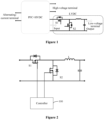
- Figure 1 is a schematic diagram of an on-board charger according to an embodiment of the present disclosure.
- An OBC includes three terminals, that is, an alternating-current terminal, a high-voltage terminal and a low-voltage terminal as shown in Figure 1 .
- the OBC includes a PFC, a HVDC and an LVDC.
- An input terminal of the PFC is connected to an alternating-current power supply.
- An input terminal of the HVDC is connected to an output terminal of the PFC.
- An output terminal of the HVDC is connected to a high-voltage battery.
- An input terminal of the LVDC is connected to the output terminal of the HVDC.
- An output terminal of the LVDC is connected to a low-voltage battery.
- the Buck circuit includes a main power transistor S1, an inductor and a controllable switching transistor S2.
- a first terminal of S1 is connected to a positive input terminal of the LVDC, and a second terminal of S1 is connected to a positive output terminal of the LVDC via the inductor.
- a first terminal of S2 is connected to the second terminal of S1, a second terminal of S2 is connected to a negative input terminal of the LVDC, and the second terminal of S2 is connected to a negative output terminal of the LVDC.
- the output terminal of the LVDC is connected in parallel with a capacitor.
- the controllable switching transistor S2 may be a freewheeling diode.
- the controllable switching transistor is used instead of the diode.
- the controllable switching transistor may be an MOS transistor. The conduction loss and the switching loss of the MOS transistor are less than the conduction loss and the switching loss of the diode respectively.
- the LVDC in order to reduce the impact on the forward current of S1 in starting up the LVDC, the LVDC is started up in a current soft start manner. Specifically, a driving signal for S1 is generated by cascading a voltage loop and a current loop in the present disclosure. Although a reference current is generated based on an output of the voltage loop, the soft start at an input terminal of the current loop, rather than the voltage loop, functions in starting up the LVDC, thereby controlling the driving signal of S1 based on the soft start of the current loop. In this way, the current flowing through S1 is gradually increased, thereby reducing the impulse current of S 1.
- Figure 2 is a schematic diagram of an LVDC in an on-board charger according to an embodiment of the present disclosure.
- the output terminal of the LVDC of the on-board charger according to the present disclosure may not be connected to a controllable switch, and an inductor L may be directly connected to the positive output terminal of the LVDC.
- the output terminal of the LVDC of the on-board charger may be connected to a controllable switch.
- a controllable switch is added to the output terminal. In a non-fault condition, the controllable switch may remain closed all the time without performing any operation in coordination with the voltage loop and the current loop.
- the on-board charger includes a power factor corrector (PFC), a high-voltage direct-current converter (HVDC), a low-voltage direct-current converter (LVDC), and a controller 100.
- An input terminal of the high-voltage direct-current converter (HVDC) is connected to an output terminal of the power factor corrector (PFC).
- An input terminal of the low-voltage direct-current converter (LVDC) is connected to an output terminal of the high-voltage direct-current converter (HVDC).
- An output terminal of the low-voltage direct-current converter (LVDC) is connected to a low-voltage battery.
- the low-voltage direct-current converter (LVDC) includes a main power transistor and a controllable switching transistor.
- the controller 100 is configured to: when the low-voltage direct-current converter is performing a startup process (that is, when the LVDC is powered on), generate a driving signal for the main power transistor S1 by soft starting a current loop to control a current flowing through the inductor L connected in series with the main power transistor S1 to be gradually increased, where a predetermined current of the current loop is determined based on a reference current outputted by a voltage loop and an output result of a soft start function; and after the low-voltage direct-current converter completes the startup process, generate a driving signal for the main power transistor by cascading the voltage loop and the current loop, where the voltage loop is configured to output the reference current to an input terminal of the current loop.
- the low-voltage direct-current converter completes the startup process.
- the difference between he output current of the low-voltage direct-current converter and the output result of the minimization unit may be positive or negative.
- the predetermined range is set to avoid repeated hiccups of the circuit.
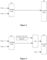
- Figure 3 is a schematic diagram of a dual-loop control manner in which a voltage loop and a current loop are cascaded according to an embodiment of the present disclosure.
- the current loop LI functions and the voltage loop LV does not function. Since the voltage loop LV does not function, a current soft start control manner, rather than a voltage soft start control manner, is adopted.
- the output voltage Vout and the predetermined reference voltage Vref are inputted to the voltage loop LV, and the Vout is relatively small in starting up the LVDC, so that the output of the voltage loop LV is invalid. That is, the voltage loop LV does not function, and only the current loop LI functions in the control loop. Since the current loop LI may be controlled in a current soft start manner, the current soft start manner is adopted in starting up the LVDC, controlling the current flowing through the S1 to gradually increase, thereby minimizing the impact on the forward current of the S 1.
- Figure 4 is a schematic diagram of a dual-loop control manner according to an embodiment of the present disclosure.
- An input of the current loop includes an output current Iout of the low-voltage direct-current converter and the output result of the minimization unit min.
- the current loop LI is configured to compare the output current Iout of the low-voltage direct-current converter with the output result of the minimization unit min, and generate a driving signal for the main power transistor based on a comparison result.
- the minimization unit min is configured to determine a smaller value between an output result of the voltage loop LV and an output result of a current soft start function. Vout is small in starting up the LVDC. Therefore, after the voltage loop LV compares Vref with Vout, a result with a large value is outputted. The minimization unit min determines a smaller value between parameters inputted to the minimization unit min. Thus, the LV performs no function on min, and min outputs the output result of the current soft start function. Therefore, in starting up the LVDC, only the current loop LI functions in the dual-loop control loop.
- the implementation form of the soft start function is not limited, as long as the current flowing through S1 can be gradually increased.
- the soft start function is a soft start ramp function.
- An output result of the soft start ramp function is a current that gradually increases over time to a predetermined current value. Due to that the startup process is not performed indefinitely, a time length of the startup process may be determined based on a time instant when the LVDC is started up and a slope of the soft start ramp function, and the predetermined current value may be determined based on the slope and the time length of the startup process. When the current reaches the predetermined current value, the soft start function exits, and thus the current soft start is completed.
- the soft start function may be reflected as a predetermined graph or table, and control is performed based on data of the graph or the table.
- the soft start function may be a variable mathematical function and may be adjusted based on Vout.
- the input of the voltage loop LV includes the predetermined reference voltage Vref and the output voltage Vout of the low-voltage direct-current converter.
- the voltage loop LV is configured to generate the reference current based on the predetermined reference voltage Vref and the output voltage Vout of the low-voltage direct-current converter, and output the reference current to the input terminal of the current loop LI.
- the current loop LI compares the reference current outputted by the voltage loop LV with Iout, and generates the driving signal for S1 based on a comparison result.
- the parameters of the current loop are variable.
- the parameters of the current loop before the LVDC is started up may be different from the parameters of the current loop after the LVDC is started up. For different processes, some feature parameters may be changed to improve a response speed.
- the reference voltage Vref of the voltage loop is set to a desired output voltage of the LVDC without performing voltage soft start processing.
- the reference current of the current loop is determined based on the output of the current soft start ramp function and the output of the voltage loop. min compares the output of the current soft start ramp function and the output of the voltage loop, and determines a smaller value between the output of the current soft start ramp function and the output of the voltage loop as the reference current of the current loop.
- the output terminal of the LVDC in a case that the output terminal of the LVDC is connected to a battery as a load, the forward current flowing through the inductor increases slowly, the output voltage increases slowly from an open-circuit voltage of the battery, and when a predetermined current value or a desired output voltage value is reached, the circuit enters into a steady state and the startup process is completed; in a case that the output terminal of the LVDC is connected to a resistor as a load, the forward current of the inductor increases slowly, the output voltage of the LVDC increases slowly from zero, and when the predetermined current value or the desired output voltage value is reached, the LVDC enters into the steady state; and in a case that the output terminal of the LVDC is connected to a mixed load formed by a battery and a resistor connected in parallel, the output voltage of the LVDC increases slowly from the open-circuit voltage of the battery, and when the predetermined current value or the desired output voltage value is reached, the LVDC enters into the steady state, and
- a duty ratio of the driving signal, generated through the current soft start, of S1 is very small and the forward current flowing through the inductor is very small.
- the driving signal of S2 is controlled to be complementary to the driving signal of S1
- the duty ratio of the driving signal of S1 is large.
- a large duty ratio of the driving signal of S2 may result in the following adverse consequences. Since the output terminal of the LVDC is connected to the battery, a large reverse current is to be generated due to the prolonged conduction of S2 in the startup process. That is, the current flowing through the inductor flows from the battery to the input terminal of the LVDC.
- the driving signal of S 1 is complementary to the driving signal of S2, or the switching state of S 1 is complementary to the switching state of S2. That is, one of two switches is switched on while the other of the two switches is switched off, and the two switches are not switched on at the same time.
- a dead time interval is configured for S 1 and S2.
- the output terminal of the LVDC is connected to a battery. Therefore, a large reverse current may flow through the inductor due to that S2 is turned off for a long time period in starting up the LVDC.
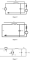
- Figure 5 shows an equivalent circuit in which S 1 is switched on and S2 is switched off.
- Figure 6 shows an equivalent circuit in which S1 is switched off and S2 is switched on.
- an input power supply Vin is connected in the circuit when S1 is switched on and S2 is switched off.
- the input voltage Vin is not connected in the circuit when S1 is switched off and S2 is switched on.
- a third switch S3 is connected between the inductor and the output terminal, as shown in Figure 7 .
- Figure 7 is a schematic diagram of a low-voltage direct-current converter.
- a third switch S3 is connected to the output terminal of the low-voltage direct-current converter, and a voltage soft start manner is adopted to avoid the reverse current flowing through the inductor. Specifically, the third switch S3 is switched on after a voltage across an output capacitor Vc reaches a voltage Vbat of the battery, so as to reduce a current impact caused by a difference between the voltage across the output capacitor Vc and the voltage of the battery.
- the hardware costs may be increased, and the charging efficiency of the entire charging pile may be reduced.
- the controller is further configured to: when the low-voltage direct-current converter is performing the startup process, control the controllable switching transistor S2 to be turned off; and after the low-voltage direct-current converter completes the startup process, control the main power transistor and the controllable switching transistor S2 to be turned on or turned off in a complementary manner.
- S2 may be controlled to remain in a disconnected state in the startup process, and after the startup process is completed, S2 is controlled to be turned on or turned off normally.
- the controller is further configured to: when the low-voltage direct-current converter is performing the startup process, control the controllable switching transistor to be turned on when the main power transistor is turned off, and control a duty ratio of the controllable switching transistor to be less than a duty ratio of the main power transistor; and after the low-voltage direct-current converter completes the startup process, control the main power transistor and the controllable switching transistor to be turned on or turned off in a complementary manner.
- the controllable switching transistor in order to avoid generating a large reverse impulse current, is controlled to operate with a small duty ratio. That is, S2 is controlled to have a short conduction time period. In addition, S2 is turned on when S1 is turned off.
- the duty ratio of S2 in starting up the low-voltage direct-current converter is limited, so as to limit the reverse current flowing through the inductor.
- the driving signal for S1 is generated in the dual-loop control manner described in the above embodiments.
- the duty ratio of the driving signal of S2 is controlled to gradually increase while ensuring that S2 and S 1 are not switched on simultaneously.
- the duty ratio of the driving signal of S2 is no longer controlled, and S2 and S1 may be controlled to operate in a complementary manner.
- S1 and S2 are not turned on or turned off in the complementary manner.
- S2 is controlled to be turned on when S1 is turned off, the driving signal of S2 is controlled not to be complementary to the driving signal of S1, and the duty ratio of S2 is reduced to shorten the conduction time period of S2, thereby avoiding a large reverse current flowing through the inductor.
- the implementation of S2 in starting up the LVDC is not limited.
- S2 is controlled to be turned off when it is detected that the LVDC outputs a reverse current.
- the duty ratio of S2 is limited, such as controlling the duty ratio of S2 to increase slowly. It is ensured that in starting up the LVDC, there is no situation in which a large reverse current flowing through the inductor due to continuous large duty ratios of S2.
- the on-board charger including the low-voltage direct-current converter is described in the above embodiments. It should be understood that the low-voltage direct-current converter is a buck DCDC converter.
- the technical solutions according to the embodiments of the present disclosure are applicable to an on-board charger, and applicable to a buck DCDC converter with an output terminal connected to a battery. Therefore, a DCDC converter according to the present disclosure is described below based on the on-board charger according to the above embodiments.
- the buck DCDC converter includes a controller, a main power transistor, a controllable switching transistor, and an inductor.
- the inductor is connected in series with the main power transistor.
- An output terminal of the buck DCDC converter is connected to a battery.
- the controller is configured to: when the buck DCDC converter is performing a startup process, generate a driving signal for the main power transistor by soft starting a current loop to control a current flowing through the inductor to be gradually increased, where a predetermined current of the current loop is determined based on a reference current outputted by a voltage loop and an output result of a soft start function; and after the buck DCDC converter completes the startup process, generate a driving signal for the main power transistor by cascading the voltage loop and the current loop, where the voltage loop is configured to output the reference current to an input terminal of the current loop.
- the current loop may be soft started by using a soft start function.
- the soft start function is a soft start ramp function
- an output result of the soft start ramp function is a current that gradually increases over time to a predetermined current value.
- An input of the current loop includes an output current of the low-voltage direct-current converter and an output result of a minimization unit.
- the current loop is configured to compare the output current of the low-voltage direct-current converter with the output result of the minimization unit, and then generate a driving signal for the main power transistor based on a comparison result.
- the minimization unit is configured to determine a smaller value between an output result of the voltage loop and an output result of the soft start function.
- the input of the voltage loop includes the predetermined reference voltage and the output voltage of the low-voltage direct-current converter.
- the voltage loop is configured to generate a reference current based on the predetermined reference voltage and the output voltage of the low-voltage direct-current converter, and output the reference current to the input terminal of the current loop.
- the controller is further configured to: when the low-voltage direct-current converter is performing the startup process, control the controllable switching transistor to be turned on when the main power transistor is turned off, and control a duty ratio of the controllable switching transistor to be less than a duty ratio of the main power transistor; and after the low-voltage direct-current converter completes the startup process, control the main power transistor and the controllable switching transistor to be turned on or turned off in a complementary manner.
- the on-board charger includes a power factor corrector, a high-voltage direct-current converter, a low-voltage direct-current converter, and a controller.
- An input terminal of the high-voltage direct-current converter is connected to an output terminal of the power factor corrector.
- An input terminal of the low-voltage direct-current converter is connected to an output terminal of the high-voltage direct-current converter.
- An output terminal of the low-voltage direct-current converter is configured to be connected to a low-voltage battery.
- the low-voltage direct-current converter includes a main power transistor and a controllable switching transistor.
- Figure 8 is a flowchart of a method for controlling an on-board charger according to the present disclosure.
- the method includes the following steps S801 and S802.
- step S801 a driving signal for the main power transistor, when the low-voltage direct-current converter is performing a startup process, is generated by soft starting a current loop to control a current flowing through an inductor connected in series with the main power transistor to be gradually increased.
- the predetermined current of the current loop is determined based on a reference current outputted by a voltage loop and an output result of a soft start function.
- the current loop may be soft started by using a soft start function.
- the soft start function is a soft start ramp function
- an output result of the soft start ramp function is a current that gradually increases over time to a predetermined current value.
- step S802 a driving signal for the main power transistor, after the low-voltage direct-current converter completes the startup process, is generated by cascading the voltage loop and the current loop.
- the voltage loop is configured to output the reference current to an input terminal of the current loop.
- the current loop functions and the voltage loop does not function. Since the voltage loop does not function, a current soft start control manner, rather than a voltage soft start control manner, is adopted.
- the output voltage and the predetermined reference voltage are inputted to the voltage loop, and the output voltage is relatively small when the low-voltage direct-current converter is started, so that the output of the voltage loop is invalid. That is, the voltage loop does not function, and only the current loop functions in the control loop.
- the current soft start manner is adopted in starting up the low-voltage direct-current converter, controlling the current flowing through the main power transistor to gradually increase, thereby minimizing the impact on the forward current of the main power transistor.
- the driving signal for the main power transistor when the low-voltage direct-current converter is performing the startup process, is generated by soft starting the current loop by: inputting an output current of the low-voltage direct-current converter and an output result of a minimization unit to the current loop; comparing, by the current loop, the output current of the low-voltage direct-current converter with the output result of the minimization unit, and generating, by the current loop, the driving signal for the main power transistor based on a comparison result; and determining, by the minimization unit, a smaller value between an output result of the voltage loop and the output result of the soft start function.
- the driving signal for the main power transistor is generated by cascading the voltage loop and the current loop by: inputting a predetermined reference voltage and an output voltage of the low-voltage direct-current converter to the voltage loop; and generating, by the voltage loop, the reference current based on the predetermined reference voltage and the output voltage of the low-voltage direct-current converter, and outputting, by the voltage loop, the reference current to the input terminal of the current loop.
- the method for controlling an on-board charger further includes: controlling, when the low-voltage direct-current converter is performing the startup process, the controllable switching transistor to be turned on when the main power transistor is turned off, and controlling a duty ratio of the controllable switching transistor to be less than a duty ratio of the main power transistor; and controlling, after the low-voltage direct-current converter completes the startup process, the main power transistor and the controllable switching transistor to be turned on or turned off in a complementary manner.
- the duty ratio of the controllable switching transistor in starting up the low-voltage direct-current converter is limited, so as to limit the reverse current flowing through the inductor.
- the driving signal for the main power transistor is generated in the dual-loop control manner described in the above embodiments.
- the duty ratio of the driving signal of the controllable switching transistor is controlled to gradually increase while ensuring that the controllable switching transistor and the main power transistor are not switched on simultaneously.
- the duty ratio of the driving signal of the controllable switching transistor is no longer controlled, and the controllable switching transistor and the main power transistor may be controlled to operate in a complementary manner.
- the computer software product may be stored in a storage medium, such as an ROM/RAM, a magnetic disk and an optical disk, which includes several instructions to cause a computer device (may be a personal computer, a server, a network communication device such as a media gateway, or the like) to execute the method according to the embodiments or some parts of the embodiments of the present disclosure.
Landscapes
- Engineering & Computer Science (AREA)
- Power Engineering (AREA)
- Transportation (AREA)
- Mechanical Engineering (AREA)
- Dc-Dc Converters (AREA)
- Charge And Discharge Circuits For Batteries Or The Like (AREA)
- Electric Propulsion And Braking For Vehicles (AREA)
Abstract
Description
- The present application claims priority to
Chinese Patent Application No. 202111575228.X, titled "ON-BOARD CHARGER, DCDC CONVERTER AND CONTROL METHOD", filed on December 21, 2021 - The present disclosure relates to the technical field of power electronics, and in particular to an on-board charger, a DCDC converter and a control method.
- Due to the increasing shortage of global energy, new energy vehicles are becoming increasingly popular. Generally, it is required to charge power battery packs of the new energy vehicles. Many new energy vehicles include on-board chargers (OBCs). Generally, an OBC includes a power factor corrector (PFC), a high-voltage direct-current converter (HVDC), and a low-voltage direct-current converter (LVDC). The PFC is connected to an alternating-current power supply, the HVDC is connected to a high-voltage battery, and the LVDC is connected to a low-voltage battery. The LVDC may obtain power from a direct-current bus and supply the power to the low-voltage battery and a low-voltage electrical appliance such as an air conditioner, a water pump, and a headlight.
- The LVDC usually operates in a low-voltage and high-current condition. For example, in a case that the LVDC is implemented as a Buck circuit, a freewheeling diode in the Buck circuit is usually replaced with a MOS transistor, so that a current flows through the MOS transistor during freewheeling, reducing a conduction on loss and a reverse recovery loss of the freewheeling diode. Generally, driving signals of a main power transistor and the MOS transistor in the Buck circuit may be complementary.
- However, in starting up the LVDC, the main power transistor bears a relatively large impulse current, seriously endangering the safety of the main power transistor.
- In order to solve the above technical problems, an on-board charger, a DCDC converter and a control method are provided according to the present disclosure, to reduce the impulse current flowing through the main power transistor in starting up the LVDC, thereby ensuring the safety of the main power transistor.
- In order to achieve the above objectives, the following technical solutions are provided according to the embodiments of the present disclosure.
- An on-board charger is provided according to an embodiment of the present disclosure. The on-board charger includes a power factor corrector, a high-voltage direct-current converter, a low-voltage direct-current converter, and a controller. An input terminal of the high-voltage direct-current converter is connected to an output terminal of the power factor corrector. An input terminal of the low-voltage direct-current converter is connected to an output terminal of the high-voltage direct-current converter or the output terminal of the power factor corrector. An output terminal of the low-voltage direct-current converter is connected to a low-voltage battery and a low-voltage load. The low-voltage direct-current converter includes a main power transistor and a controllable switching transistor. The controller is configured to: when the low-voltage direct-current converter is performing a startup process, generate a driving signal for the main power transistor by soft starting a current loop to control a current flowing through an inductor connected in series with the main power transistor to be gradually increased, where a predetermined current of the current loop is determined based on a reference current outputted by a voltage loop and an output result of a soft start function; and after the low-voltage direct-current converter completes the startup process, generate a driving signal for the main power transistor by cascading the voltage loop and the current loop, where the voltage loop is configured to output the reference current to an input terminal of the current loop.
- Preferably, an input of the current loop includes an output current of the low-voltage direct-current converter and an output result of a minimization unit. The current loop is configured to compare the output current of the low-voltage direct-current converter with the output result of the minimization unit, and then generate the driving signal for the main power transistor based on a comparison result. The minimization unit is configured to determine a smaller value between an output result of the voltage loop and the output result of the soft start function. After a difference between the output current of the low-voltage direct-current converter and the output result of the minimization unit is controlled within a predetermined range, the low-voltage direct-current converter completes the startup process.
- Preferably, an input of the voltage loop includes a predetermined reference voltage and an output voltage of the low-voltage direct-current converter. The voltage loop is configured to generate the reference current based on the predetermined reference voltage and the output voltage of the low-voltage direct-current converter and output the reference current to the input terminal of the current loop.
- Preferably, the soft start function is a soft start ramp function, and an output result of the soft start ramp function is a current that gradually increases over time to a predetermined current value.
- Preferably, the controller is further configured to: when the low-voltage direct-current converter is performing the startup process, control the controllable switching transistor to be turned off; and after the low-voltage direct-current converter completes the startup process, control the main power transistor and the controllable switching transistor to be turned on or turned off in a complementary manner.
- Preferably, the controller is further configured to: when the low-voltage direct-current converter is performing the startup process, control the controllable switching transistor to be turned on when the main power transistor is turned off, and control a duty ratio of the controllable switching transistor to be less than a duty ratio of the main power transistor; and after the low-voltage direct-current converter completes the startup process, control the main power transistor and the controllable switching transistor to be turned on or turned off in a complementary manner.
- A buck DCDC converter is provided according to the present disclosure. The buck DCDC converter includes a controller, a main power transistor, a controllable switching transistor, and an inductor. The inductor is connected in series with the main power transistor. An output terminal of the buck DCDC converter is connected to a battery. The controller is configured to: when the buck DCDC converter is performing a startup process, generate a driving signal for the main power transistor by soft starting a current loop to control a current flowing through the inductor to be gradually increased, where a predetermined current of the current loop is determined based on a reference current outputted by a voltage loop and an output result of a soft start function; and after the buck DCDC converter completes the startup process, generate a driving signal for the main power transistor by cascading the voltage loop and the current loop, where the voltage loop is configured to output the reference current to an input terminal of the current loop.
- Preferably, an input of the current loop includes an output current of the low-voltage direct-current converter and an output result of a minimization unit. The current loop is configured to compare the output current of the low-voltage direct-current converter with the output result of the minimization unit, and then generate the driving signal for the main power transistor based on a comparison result. The minimization unit is configured to determine a smaller value between an output result of the voltage loop and the output result of the soft start function.
- Preferably, an input of the voltage loop includes a predetermined reference voltage and an output voltage of the low-voltage direct-current converter. The voltage loop is configured to generate the reference current based on the predetermined reference voltage and the output voltage of the low-voltage direct-current converter and output the reference current to the input terminal of the current loop.
- Preferably, the soft start function is a soft start ramp function, and an output result of the soft start ramp function is a current that gradually increases over time to a predetermined current value.
- Preferably, the controller is further configured to: when the low-voltage direct-current converter is performing the startup process, control the controllable switching transistor to be turned on when the main power transistor is turned off, and control a duty ratio of the controllable switching transistor to be less than a duty ratio of the main power transistor; and after the low-voltage direct-current converter completes the startup process, control the main power transistor and the controllable switching transistor to be turned on or turned off in a complementary manner.
- A method for controlling an on-board charger is provided according to the present disclosure. The on-board charger includes a power factor corrector, a high-voltage direct-current converter, a low-voltage direct-current converter and a controller. An input terminal of the high-voltage direct-current converter is connected to an output terminal of the power factor corrector. An input terminal of the low-voltage direct-current converter is connected to an output terminal of the high-voltage direct-current converter. An output terminal of the low-voltage direct-current converter is connected to a low-voltage battery. The low-voltage direct-current converter includes a main power transistor and a controllable switching transistor. The method includes: generating, when the low-voltage direct-current converter is performing a startup process, a driving signal for the main power transistor by soft starting a current loop to control a current flowing through an inductor connected in series with the main power transistor to be gradually increased, where a predetermined current of the current loop is determined based on a reference current outputted by a voltage loop and an output result of a soft start function; and generating, after the low-voltage direct-current converter completes the startup process, a driving signal for the main power transistor by cascading the voltage loop and the current loop, where the voltage loop is configured to output the reference current to an input terminal of the current loop.
- Preferably, the generating, when the low-voltage direct-current converter is performing a startup process, a driving signal for the main power transistor by soft starting a current loop includes: inputting an output current of the low-voltage direct-current converter and an output result of a minimization unit to the current loop; comparing, by the current loop, the output current of the low-voltage direct-current converter with the output result of the minimization unit, and generating, by the current loop, the driving signal for the main power transistor based on a comparison result; and determining, by the minimization unit, a smaller value between an output result of the voltage loop and the output result of the soft start function.
- Preferably, the generating a driving signal for the main power transistor by cascading the voltage loop and the current loop includes: inputting a predetermined reference voltage and an output voltage of the low-voltage direct-current converter to the voltage loop; and generating, by the voltage loop, the reference current based on the predetermined reference voltage and the output voltage of the low-voltage direct-current converter, and outputting, by the voltage loop, the reference current to the input terminal of the current loop.
- Preferably, the method further includes: controlling, when the low-voltage direct-current converter is performing the startup process, the controllable switching transistor to be turned on when the main power transistor is turned off, and controlling a duty ratio of the controllable switching transistor to be less than a duty ratio of the main power transistor; and controlling, after the low-voltage direct-current converter completes the startup process, the main power transistor and the controllable switching transistor to be turned on or turned off in a complementary manner.
- Preferably, the soft start function is a soft start ramp function, and an output result of the soft start ramp function is a current that gradually increases over time to a predetermined current value.
- It can be seen from the above technical solutions that the present disclosure has the following beneficial effects.
- In the technical solutions according to the present disclosure, in order to reduce the impulse current flowing through the main power transistor in starting up the low-voltage direct-current converter, the current loop functions and the voltage loop does not function. Since the voltage loop does not function, a current soft start control manner, rather than a voltage soft start control manner, is adopted. The output voltage and the predetermined reference voltage are inputted to the voltage loop, and the output voltage is relatively small in starting up the low-voltage direct-current converter, so that the output of the voltage loop is invalid. That is, the voltage loop does not function, and only the current loop functions in the control loop. Since the current loop may be controlled in a current soft start manner, the current soft start manner is adopted in starting up the low-voltage direct-current converter, controlling the current flowing through the main power transistor to gradually increase, thereby minimizing the impact on the forward current of the main power transistor.
- In order to more clearly describe the technical solutions in the embodiments of the present disclosure or the technical solutions in the conventional technology, drawings to be used in the description of the embodiments or the conventional technology are briefly described hereinafter. It is apparent that the drawings described below are merely used for describing the embodiments of the present disclosure, and those skilled in the art can obtain other drawings according to the provided drawings without any creative effort.
-
Figure 1 is a schematic diagram of an on-board charger according to an embodiment of the present disclosure; -
Figure 2 is a schematic diagram of an LVDC in an on-board charger according to an embodiment of the present disclosure; -
Figure 3 is a schematic diagram of a dual-loop control manner in which a voltage loop and a current loop are cascaded according to an embodiment of the present disclosure; -
Figure 4 a schematic diagram shows a current soft start manner according to an embodiment of the present disclosure; -
Figure 5 shows an equivalent circuit in which S1 is turned on and S2 is turned off according to an embodiment of the present disclosure; -
Figure 6 shows an equivalent circuit in which S1 is turned off and S2 is turned on according to an embodiment of the present disclosure; -
Figure 7 is a schematic diagram of a low-voltage direct-current converter according to the conventional technology; and -
Figure 8 is a flowchart of a method for controlling an on-board charger according to an embodiment of the present disclosure. - In order to facilitate understanding the solutions according to the embodiments of the present disclosure, an application scenario for the solutions according to the embodiments of the present disclosure is described before describing the method according to the embodiments of the present disclosure.
- Referring to
Figure 1, Figure 1 is a schematic diagram of an on-board charger according to an embodiment of the present disclosure. - An OBC according to an embodiment of the present disclosure includes three terminals, that is, an alternating-current terminal, a high-voltage terminal and a low-voltage terminal as shown in
Figure 1 . The OBC includes a PFC, a HVDC and an LVDC. An input terminal of the PFC is connected to an alternating-current power supply. An input terminal of the HVDC is connected to an output terminal of the PFC. An output terminal of the HVDC is connected to a high-voltage battery. An input terminal of the LVDC is connected to the output terminal of the HVDC. An output terminal of the LVDC is connected to a low-voltage battery. - In the embodiment, descriptions are provided by taking the LVDC as a bulk converter, such as a Buck circuit, as an example. The Buck circuit includes a main power transistor S1, an inductor and a controllable switching transistor S2. A first terminal of S1 is connected to a positive input terminal of the LVDC, and a second terminal of S1 is connected to a positive output terminal of the LVDC via the inductor. A first terminal of S2 is connected to the second terminal of S1, a second terminal of S2 is connected to a negative input terminal of the LVDC, and the second terminal of S2 is connected to a negative output terminal of the LVDC. The output terminal of the LVDC is connected in parallel with a capacitor. In the conventional Buck circuit, the controllable switching transistor S2 may be a freewheeling diode. In order to reduce power consumption caused by the diode, the controllable switching transistor is used instead of the diode. For example, the controllable switching transistor may be an MOS transistor. The conduction loss and the switching loss of the MOS transistor are less than the conduction loss and the switching loss of the diode respectively.
- In the conventional technology, in order to solve the problem of an excessive impulse current in starting up the LVDC, a controllable switch is usually connected in series at the output terminal of the LVDC and a voltage soft start control manner is adopted. However, the solution of connecting the controllable switch in series at the output terminal of the LVDC increases the hardware costs.
- In the present disclosure, in order to reduce the impact on the forward current of S1 in starting up the LVDC, the LVDC is started up in a current soft start manner. Specifically, a driving signal for S1 is generated by cascading a voltage loop and a current loop in the present disclosure. Although a reference current is generated based on an output of the voltage loop, the soft start at an input terminal of the current loop, rather than the voltage loop, functions in starting up the LVDC, thereby controlling the driving signal of S1 based on the soft start of the current loop. In this way, the current flowing through S1 is gradually increased, thereby reducing the impulse current of
S 1. - In order to make the above objectives, features and advantages of the present disclosure obvious and understandable, the embodiments of the present disclosure are described in detail below in conjunction with the drawings and the embodiments.
- Referring to
Figure 2, Figure 2 is a schematic diagram of an LVDC in an on-board charger according to an embodiment of the present disclosure. - It should be understood that as the architecture of the on-board charger according to the present disclosure shown in
Figure 1 , the output terminal of the LVDC of the on-board charger according to the present disclosure may not be connected to a controllable switch, and an inductor L may be directly connected to the positive output terminal of the LVDC. The output terminal of the LVDC of the on-board charger may be connected to a controllable switch. For example, for safety, a controllable switch is added to the output terminal. In a non-fault condition, the controllable switch may remain closed all the time without performing any operation in coordination with the voltage loop and the current loop. - The technical solutions according to the present disclosure are described in detail below in conjunction with
Figure 1 and Figure 2 . - In the embodiment, the on-board charger includes a power factor corrector (PFC), a high-voltage direct-current converter (HVDC), a low-voltage direct-current converter (LVDC), and a
controller 100. An input terminal of the high-voltage direct-current converter (HVDC) is connected to an output terminal of the power factor corrector (PFC). An input terminal of the low-voltage direct-current converter (LVDC) is connected to an output terminal of the high-voltage direct-current converter (HVDC). An output terminal of the low-voltage direct-current converter (LVDC) is connected to a low-voltage battery. The low-voltage direct-current converter (LVDC) includes a main power transistor and a controllable switching transistor. - The
controller 100 is configured to: when the low-voltage direct-current converter is performing a startup process (that is, when the LVDC is powered on), generate a driving signal for the main power transistor S1 by soft starting a current loop to control a current flowing through the inductor L connected in series with the main power transistor S1 to be gradually increased, where a predetermined current of the current loop is determined based on a reference current outputted by a voltage loop and an output result of a soft start function; and after the low-voltage direct-current converter completes the startup process, generate a driving signal for the main power transistor by cascading the voltage loop and the current loop, where the voltage loop is configured to output the reference current to an input terminal of the current loop. - When a difference between an output current of the low-voltage direct-current converter and an output result of a minimization unit is controlled within a predetermined range, such as within negative 15% to positive 15%, the low-voltage direct-current converter completes the startup process. The difference between he output current of the low-voltage direct-current converter and the output result of the minimization unit may be positive or negative. The predetermined range is set to avoid repeated hiccups of the circuit.
- Referring to
Figure 3, Figure 3 is a schematic diagram of a dual-loop control manner in which a voltage loop and a current loop are cascaded according to an embodiment of the present disclosure. - In the technical solutions according to the embodiments of the present disclosure, in order to reduce the impact on the forward current of S1 in starting up the LVDC, the current loop LI functions and the voltage loop LV does not function. Since the voltage loop LV does not function, a current soft start control manner, rather than a voltage soft start control manner, is adopted. The output voltage Vout and the predetermined reference voltage Vref are inputted to the voltage loop LV, and the Vout is relatively small in starting up the LVDC, so that the output of the voltage loop LV is invalid. That is, the voltage loop LV does not function, and only the current loop LI functions in the control loop. Since the current loop LI may be controlled in a current soft start manner, the current soft start manner is adopted in starting up the LVDC, controlling the current flowing through the S1 to gradually increase, thereby minimizing the impact on the forward current of the
S 1. - The technical solution of current soft start according to the embodiments of the present disclosure is described in detail below in conjunction with
Figure 4 . - Referring to
Figure 4, Figure 4 is a schematic diagram of a dual-loop control manner according to an embodiment of the present disclosure. - An input of the current loop includes an output current Iout of the low-voltage direct-current converter and the output result of the minimization unit min. The current loop LI is configured to compare the output current Iout of the low-voltage direct-current converter with the output result of the minimization unit min, and generate a driving signal for the main power transistor based on a comparison result. The minimization unit min is configured to determine a smaller value between an output result of the voltage loop LV and an output result of a current soft start function. Vout is small in starting up the LVDC. Therefore, after the voltage loop LV compares Vref with Vout, a result with a large value is outputted. The minimization unit min determines a smaller value between parameters inputted to the minimization unit min. Thus, the LV performs no function on min, and min outputs the output result of the current soft start function. Therefore, in starting up the LVDC, only the current loop LI functions in the dual-loop control loop.
- In the embodiments of the present disclosure, the implementation form of the soft start function is not limited, as long as the current flowing through S1 can be gradually increased. For example, in an implementation, the soft start function is a soft start ramp function. An output result of the soft start ramp function is a current that gradually increases over time to a predetermined current value. Due to that the startup process is not performed indefinitely, a time length of the startup process may be determined based on a time instant when the LVDC is started up and a slope of the soft start ramp function, and the predetermined current value may be determined based on the slope and the time length of the startup process. When the current reaches the predetermined current value, the soft start function exits, and thus the current soft start is completed. In starting up the LVDC, only the current loop functions and the current loop has the function of current soft start, so that it can be ensured that the forward current flowing through S1 is gradually increased, avoiding an excessive impact on S1, thereby ensuring the safety of
S 1. In addition, the soft start function may be reflected as a predetermined graph or table, and control is performed based on data of the graph or the table. For example, the soft start function may be a variable mathematical function and may be adjusted based on Vout. - The input of the voltage loop LV includes the predetermined reference voltage Vref and the output voltage Vout of the low-voltage direct-current converter. The voltage loop LV is configured to generate the reference current based on the predetermined reference voltage Vref and the output voltage Vout of the low-voltage direct-current converter, and output the reference current to the input terminal of the current loop LI.
- After the LVDC completes the startup process, Vout gradually increases, and the output of the voltage loop LV is valid and affects the output result of min. The output result of min is the reference current value affected by the voltage loop LV. The current loop LI compares the reference current outputted by the voltage loop LV with Iout, and generates the driving signal for S1 based on a comparison result.
- In addition, the parameters of the current loop are variable. The parameters of the current loop before the LVDC is started up may be different from the parameters of the current loop after the LVDC is started up. For different processes, some feature parameters may be changed to improve a response speed. In the charging pile according to the present disclosure, the reference voltage Vref of the voltage loop is set to a desired output voltage of the LVDC without performing voltage soft start processing. The reference current of the current loop is determined based on the output of the current soft start ramp function and the output of the voltage loop. min compares the output of the current soft start ramp function and the output of the voltage loop, and determines a smaller value between the output of the current soft start ramp function and the output of the voltage loop as the reference current of the current loop.
- With the above solutions, in a case that the output terminal of the LVDC is connected to a battery as a load, the forward current flowing through the inductor increases slowly, the output voltage increases slowly from an open-circuit voltage of the battery, and when a predetermined current value or a desired output voltage value is reached, the circuit enters into a steady state and the startup process is completed; in a case that the output terminal of the LVDC is connected to a resistor as a load, the forward current of the inductor increases slowly, the output voltage of the LVDC increases slowly from zero, and when the predetermined current value or the desired output voltage value is reached, the LVDC enters into the steady state; and in a case that the output terminal of the LVDC is connected to a mixed load formed by a battery and a resistor connected in parallel, the output voltage of the LVDC increases slowly from the open-circuit voltage of the battery, and when the predetermined current value or the desired output voltage value is reached, the LVDC enters into the steady state, and the output current is automatically distributed based on a proportional relationship between an equivalent internal resistance of the battery and an equivalent internal resistance of the resistor.
- After LVDC is just started up, a duty ratio of the driving signal, generated through the current soft start, of S1 is very small and the forward current flowing through the inductor is very small. Thus, in a case that the driving signal of S2 is controlled to be complementary to the driving signal of S1, the duty ratio of the driving signal of S1 is large. A large duty ratio of the driving signal of S2 may result in the following adverse consequences. Since the output terminal of the LVDC is connected to the battery, a large reverse current is to be generated due to the prolonged conduction of S2 in the startup process. That is, the current flowing through the inductor flows from the battery to the input terminal of the LVDC.
- It should be understood that the driving signal of
S 1 is complementary to the driving signal of S2, or the switching state ofS 1 is complementary to the switching state of S2. That is, one of two switches is switched on while the other of the two switches is switched off, and the two switches are not switched on at the same time. In addition, for safety, a dead time interval is configured forS 1 and S2. - In order to enable those skilled in the art to more fully understand the technical solutions according to the present disclosure, the disadvantages caused by the large duty ratio of S2 in starting up the LVDC are described below in conjunction with the drawings.
- In the application scenario of the on-board charger, the output terminal of the LVDC is connected to a battery. Therefore, a large reverse current may flow through the inductor due to that S2 is turned off for a long time period in starting up the LVDC.
- Referring to
Figure 5, Figure 5 shows an equivalent circuit in whichS 1 is switched on and S2 is switched off. Referring toFigure 6, Figure 6 shows an equivalent circuit in which S1 is switched off and S2 is switched on. - As can be seen from
Figure 5 , an input power supply Vin is connected in the circuit when S1 is switched on and S2 is switched off. As can be seen fromFigure 6 , the input voltage Vin is not connected in the circuit when S1 is switched off and S2 is switched on. - In the conventional technology, in order to prevent S2 from being impacted by the reverse current from the battery at the output terminal in starting up the LVDC, a third switch S3 is connected between the inductor and the output terminal, as shown in
Figure 7 . - Referring to
Figure 7, Figure 7 is a schematic diagram of a low-voltage direct-current converter. - In
Figure 7 , a third switch S3 is connected to the output terminal of the low-voltage direct-current converter, and a voltage soft start manner is adopted to avoid the reverse current flowing through the inductor. Specifically, the third switch S3 is switched on after a voltage across an output capacitor Vc reaches a voltage Vbat of the battery, so as to reduce a current impact caused by a difference between the voltage across the output capacitor Vc and the voltage of the battery. However, with the solution shown inFigure 7 , the hardware costs may be increased, and the charging efficiency of the entire charging pile may be reduced. - In order to not increase the hardware costs, that is, to avoid the reverse impulse current in starting up the LVDC without adding the third switch S3, the following two technical solutions are provided according to the present disclosure.
- In a first technical solution, the controller is further configured to: when the low-voltage direct-current converter is performing the startup process, control the controllable switching transistor S2 to be turned off; and after the low-voltage direct-current converter completes the startup process, control the main power transistor and the controllable switching transistor S2 to be turned on or turned off in a complementary manner. In order to avoid the reverse impulse current generated by the battery impacting S1 and S2 in starting up the low-voltage direct-current converter, S2 may be controlled to remain in a disconnected state in the startup process, and after the startup process is completed, S2 is controlled to be turned on or turned off normally.
- In a second technical solution, the controller is further configured to: when the low-voltage direct-current converter is performing the startup process, control the controllable switching transistor to be turned on when the main power transistor is turned off, and control a duty ratio of the controllable switching transistor to be less than a duty ratio of the main power transistor; and after the low-voltage direct-current converter completes the startup process, control the main power transistor and the controllable switching transistor to be turned on or turned off in a complementary manner.
- In the second technical solution, in order to avoid generating a large reverse impulse current, the controllable switching transistor is controlled to operate with a small duty ratio. That is, S2 is controlled to have a short conduction time period. In addition, S2 is turned on when S1 is turned off.
- In order to avoid generating a large reverse current flowing through the inductor, the duty ratio of S2 in starting up the low-voltage direct-current converter is limited, so as to limit the reverse current flowing through the inductor. Specifically, in the startup process of the low-voltage direct-current converter, the driving signal for S1 is generated in the dual-loop control manner described in the above embodiments. Based on the duty ratio of the driving signal of S1, the duty ratio of the driving signal of S2 is controlled to gradually increase while ensuring that S2 and
S 1 are not switched on simultaneously. After the current soft start is completed, the duty ratio of the driving signal of S2 is no longer controlled, and S2 and S1 may be controlled to operate in a complementary manner. - In the technical solutions according to the present disclosure, in starting up the low-voltage direct-current converter, S1 and S2 are not turned on or turned off in the complementary manner. S2 is controlled to be turned on when S1 is turned off, the driving signal of S2 is controlled not to be complementary to the driving signal of S1, and the duty ratio of S2 is reduced to shorten the conduction time period of S2, thereby avoiding a large reverse current flowing through the inductor.
- In the present disclosure, the implementation of S2 in starting up the LVDC is not limited. For example, S2 is controlled to be turned off when it is detected that the LVDC outputs a reverse current. Alternatively, in the current soft start process, the duty ratio of S2 is limited, such as controlling the duty ratio of S2 to increase slowly. It is ensured that in starting up the LVDC, there is no situation in which a large reverse current flowing through the inductor due to continuous large duty ratios of S2.
- The on-board charger including the low-voltage direct-current converter is described in the above embodiments. It should be understood that the low-voltage direct-current converter is a buck DCDC converter. The technical solutions according to the embodiments of the present disclosure are applicable to an on-board charger, and applicable to a buck DCDC converter with an output terminal connected to a battery. Therefore, a DCDC converter according to the present disclosure is described below based on the on-board charger according to the above embodiments.
- Referring to
Figure 2 , a buck DCDC converter according to the present disclosure, reference is described briefly. Detailed operation principles may refer to the above descriptions about the on-board charger, and are not repeated herein. - In an embodiment, the buck DCDC converter includes a controller, a main power transistor, a controllable switching transistor, and an inductor. The inductor is connected in series with the main power transistor. An output terminal of the buck DCDC converter is connected to a battery.
- The controller is configured to: when the buck DCDC converter is performing a startup process, generate a driving signal for the main power transistor by soft starting a current loop to control a current flowing through the inductor to be gradually increased, where a predetermined current of the current loop is determined based on a reference current outputted by a voltage loop and an output result of a soft start function; and after the buck DCDC converter completes the startup process, generate a driving signal for the main power transistor by cascading the voltage loop and the current loop, where the voltage loop is configured to output the reference current to an input terminal of the current loop.
- The current loop may be soft started by using a soft start function. For example, the soft start function is a soft start ramp function, and an output result of the soft start ramp function is a current that gradually increases over time to a predetermined current value.
- An input of the current loop includes an output current of the low-voltage direct-current converter and an output result of a minimization unit. The current loop is configured to compare the output current of the low-voltage direct-current converter with the output result of the minimization unit, and then generate a driving signal for the main power transistor based on a comparison result. The minimization unit is configured to determine a smaller value between an output result of the voltage loop and an output result of the soft start function.
- The input of the voltage loop includes the predetermined reference voltage and the output voltage of the low-voltage direct-current converter. The voltage loop is configured to generate a reference current based on the predetermined reference voltage and the output voltage of the low-voltage direct-current converter, and output the reference current to the input terminal of the current loop.
- The controller is further configured to: when the low-voltage direct-current converter is performing the startup process, control the controllable switching transistor to be turned on when the main power transistor is turned off, and control a duty ratio of the controllable switching transistor to be less than a duty ratio of the main power transistor; and after the low-voltage direct-current converter completes the startup process, control the main power transistor and the controllable switching transistor to be turned on or turned off in a complementary manner.
- Based on the on-board charger according to the above embodiments, a method for controlling an on-board charger is further provided according to the present disclosure. The method is described in detail below in conjunction with the drawings.
- A method for controlling an on-board charger is provided according to an embodiment of the present disclosure. The on-board charger includes a power factor corrector, a high-voltage direct-current converter, a low-voltage direct-current converter, and a controller. An input terminal of the high-voltage direct-current converter is connected to an output terminal of the power factor corrector. An input terminal of the low-voltage direct-current converter is connected to an output terminal of the high-voltage direct-current converter. An output terminal of the low-voltage direct-current converter is configured to be connected to a low-voltage battery. The low-voltage direct-current converter includes a main power transistor and a controllable switching transistor.
- Referring to
Figure 8, Figure 8 is a flowchart of a method for controlling an on-board charger according to the present disclosure. - The method includes the following steps S801 and S802.
- In step S801, a driving signal for the main power transistor, when the low-voltage direct-current converter is performing a startup process, is generated by soft starting a current loop to control a current flowing through an inductor connected in series with the main power transistor to be gradually increased. The predetermined current of the current loop is determined based on a reference current outputted by a voltage loop and an output result of a soft start function.
- The current loop may be soft started by using a soft start function. For example, the soft start function is a soft start ramp function, and an output result of the soft start ramp function is a current that gradually increases over time to a predetermined current value.
- In step S802, a driving signal for the main power transistor, after the low-voltage direct-current converter completes the startup process, is generated by cascading the voltage loop and the current loop. The voltage loop is configured to output the reference current to an input terminal of the current loop.
- In the method according to the embodiments of the present disclosure and the technical solutions according to the present disclosure, in order to reduce the impulse current flowing through the main power transistor in starting up the low-voltage direct-current converter, the current loop functions and the voltage loop does not function. Since the voltage loop does not function, a current soft start control manner, rather than a voltage soft start control manner, is adopted. The output voltage and the predetermined reference voltage are inputted to the voltage loop, and the output voltage is relatively small when the low-voltage direct-current converter is started, so that the output of the voltage loop is invalid. That is, the voltage loop does not function, and only the current loop functions in the control loop. Since the current loop may be controlled in a current soft start manner, the current soft start manner is adopted in starting up the low-voltage direct-current converter, controlling the current flowing through the main power transistor to gradually increase, thereby minimizing the impact on the forward current of the main power transistor.
- The driving signal for the main power transistor, when the low-voltage direct-current converter is performing the startup process, is generated by soft starting the current loop by: inputting an output current of the low-voltage direct-current converter and an output result of a minimization unit to the current loop; comparing, by the current loop, the output current of the low-voltage direct-current converter with the output result of the minimization unit, and generating, by the current loop, the driving signal for the main power transistor based on a comparison result; and determining, by the minimization unit, a smaller value between an output result of the voltage loop and the output result of the soft start function.
- The driving signal for the main power transistor is generated by cascading the voltage loop and the current loop by: inputting a predetermined reference voltage and an output voltage of the low-voltage direct-current converter to the voltage loop; and generating, by the voltage loop, the reference current based on the predetermined reference voltage and the output voltage of the low-voltage direct-current converter, and outputting, by the voltage loop, the reference current to the input terminal of the current loop.
- The method for controlling an on-board charger according to the embodiments of the present disclosure further includes: controlling, when the low-voltage direct-current converter is performing the startup process, the controllable switching transistor to be turned on when the main power transistor is turned off, and controlling a duty ratio of the controllable switching transistor to be less than a duty ratio of the main power transistor; and controlling, after the low-voltage direct-current converter completes the startup process, the main power transistor and the controllable switching transistor to be turned on or turned off in a complementary manner.
- In order to avoid generating a large reverse current flowing through the inductor, the duty ratio of the controllable switching transistor in starting up the low-voltage direct-current converter is limited, so as to limit the reverse current flowing through the inductor. Specifically, in the startup process of the low-voltage direct-current converter, the driving signal for the main power transistor is generated in the dual-loop control manner described in the above embodiments. Based on the duty ratio of the driving signal of the main power transistor, the duty ratio of the driving signal of the controllable switching transistor is controlled to gradually increase while ensuring that the controllable switching transistor and the main power transistor are not switched on simultaneously. After the current soft start is completed, the duty ratio of the driving signal of the controllable switching transistor is no longer controlled, and the controllable switching transistor and the main power transistor may be controlled to operate in a complementary manner.
- As can be seen from the above embodiments, it may be clearly appreciated by those skilled in the art that all or a part of steps in the methods according to the above embodiments may be implemented by means of software and a necessary general hardware platform. Based on such understanding, the essential part of the technical solutions of the present disclosure or the part of the technical solutions of the present disclosure contributed to the conventional technology may be embodied in a form of a software product. The computer software product may be stored in a storage medium, such as an ROM/RAM, a magnetic disk and an optical disk, which includes several instructions to cause a computer device (may be a personal computer, a server, a network communication device such as a media gateway, or the like) to execute the method according to the embodiments or some parts of the embodiments of the present disclosure.
- It should be noted that the embodiments in this specification are described in a progressive manner. Each of the embodiments focuses on differences with other embodiments, and the same or similar parts of the embodiments may be with reference to each other. Description of the method disclosed in the embodiments is simplified, since the method corresponds to the system disclosed in the embodiments, reference may be made to the description of the system for related explanations.
- It should further be noted that, the term "include", "comprise" or any variant thereof is intended to indicate nonexclusive inclusion so that a process, method, article or device including a series of elements includes not only the explicitly described elements but also other elements not explicitly listed or an element(s) inherent to the process, method, article or device. Unless expressively limited otherwise, the statement "comprising (including) one..." does not exclude a case that other similar elements may exist in the process, method, article or device. With the description of the embodiments disclosed above, those skilled in the art may implement or use the present disclosure. Various modifications made to the embodiments are apparent to those skilled in the art, and the general principles defined herein may be implemented in other embodiments without departing from the spirit or scope of the present disclosure. Therefore, the present disclosure is not limited to the embodiments described herein, but should comply with the widest scope consistent with the principles and novel features disclosed herein.
Claims (16)
- An on-board charger, comprising:a power factor corrector;a high-voltage direct-current converter;a low-voltage direct-current converter; anda controller; whereinan input terminal of the high-voltage direct-current converter is connected to an output terminal of the power factor corrector, an input terminal of the low-voltage direct-current converter is connected to an output terminal of the high-voltage direct-current converter or the output terminal of the power factor corrector, an output terminal of the low-voltage direct-current converter is connected to a low-voltage battery and a low-voltage load, and the low-voltage direct-current converter comprises a main power transistor and a controllable switching transistor; andthe controller is configured to:when the low-voltage direct-current converter is performing a startup process, generate a driving signal for the main power transistor by soft starting a current loop to control a current flowing through an inductor connected in series with the main power transistor to be gradually increased, wherein a predetermined current of the current loop is determined based on a reference current outputted by a voltage loop and an output result of a soft start function; andafter the low-voltage direct-current converter completes the startup process, generate a driving signal for the main power transistor by cascading the voltage loop and the current loop, wherein the voltage loop is configured to output the reference current to an input terminal of the current loop.
- The on-board charger according to claim 1, whereinan input of the current loop comprises an output current of the low-voltage direct-current converter and an output result of a minimization unit;the current loop is configured to compare the output current of the low-voltage direct-current converter with the output result of the minimization unit, and then generate the driving signal for the main power transistor based on a comparison result;the minimization unit is configured to determine a smaller value between an output result of the voltage loop and the output result of the soft start function; andafter a difference between the output current of the low-voltage direct-current converter and the output result of the minimization unit is controlled within a predetermined range, the low-voltage direct-current converter completes the startup process.
- The on-board charger according to claim 2, wherein an input of the voltage loop comprises a predetermined reference voltage and an output voltage of the low-voltage direct-current converter, the voltage loop is configured to generate the reference current based on the predetermined reference voltage and the output voltage of the low-voltage direct-current converter and output the reference current to the input terminal of the current loop.
- The on-board charger according to claim 3, wherein the soft start function is a soft start ramp function, and an output result of the soft start ramp function is a current that gradually increases over time to a predetermined current value.
- The on-board charger according to any one of claims 1 to 4, wherein the controller is further configured to:when the low-voltage direct-current converter is performing the startup process, control the controllable switching transistor to be turned off; andafter the low-voltage direct-current converter completes the startup process, control the main power transistor and the controllable switching transistor to be turned on or turned off in a complementary manner.
- The on-board charger according to any one of claims 1 to 4, wherein the controller is further configured to:when the low-voltage direct-current converter is performing the startup process, control the controllable switching transistor to be turned on when the main power transistor is turned off, and control a duty ratio of the controllable switching transistor to be less than a duty ratio of the main power transistor; andafter the low-voltage direct-current converter completes the startup process, control the main power transistor and the controllable switching transistor to be turned on or turned off in a complementary manner.
- A buck DCDC converter, comprising:a controller;a main power transistor;a controllable switching transistor; andan inductor; whereinthe inductor is connected in series with the main power transistor;an output terminal of the buck DCDC converter is connected to a battery; andthe controller is configured to:when the buck DCDC converter is performing a startup process, generate a driving signal for the main power transistor by soft starting a current loop to control a current flowing through the inductor to be gradually increased, wherein a predetermined current of the current loop is determined based on a reference current outputted by a voltage loop and an output result of a soft start function; andafter the buck DCDC converter completes the startup process, generate a driving signal for the main power transistor by cascading the voltage loop and the current loop, wherein the voltage loop is configured to output the reference current to an input terminal of the current loop.
- The buck DCDC converter according to claim 7, whereinan input of the current loop comprises an output current of the low-voltage direct-current converter and an output result of a minimization unit;the current loop is configured to compare the output current of the low-voltage direct-current converter with the output result of the minimization unit, and then generate the driving signal for the main power transistor based on a comparison result; andthe minimization unit is configured to determine a smaller value between an output result of the voltage loop and the output result of the soft start function.
- The buck DCDC converter according to claim 8, wherein an input of the voltage loop comprises a predetermined reference voltage and an output voltage of the low-voltage direct-current converter, the voltage loop is configured to generate the reference current based on the predetermined reference voltage and the output voltage of the low-voltage direct-current converter and output the reference current to the input terminal of the current loop.
- The buck DCDC converter according to claim 8, wherein the soft start function is a soft start ramp function, and an output result of the soft start ramp function is a current that gradually increases over time to a predetermined current value.
- The buck DCDC converter according to any one of claims 7 to 10, wherein the controller is further configured to:when the low-voltage direct-current converter is performing the startup process, control the controllable switching transistor to be turned on when the main power transistor is turned off, and control a duty ratio of the controllable switching transistor to be less than a duty ratio of the main power transistor; andafter the low-voltage direct-current converter completes the startup process, control the main power transistor and the controllable switching transistor to be turned on or turned off in a complementary manner.
- A method for controlling an on-board charger, wherein the on-board charger comprises a power factor corrector, a high-voltage direct-current converter, a low-voltage direct-current converter and a controller, an input terminal of the high-voltage direct-current converter is connected to an output terminal of the power factor corrector, an input terminal of the low-voltage direct-current converter is connected to an output terminal of the high-voltage direct-current converter, an output terminal of the low-voltage direct-current converter is connected to a low-voltage battery, and the low-voltage direct-current converter comprises a main power transistor and a controllable switching transistor; and
the method comprises:generating, when the low-voltage direct-current converter is performing a startup process, a driving signal for the main power transistor by soft starting a current loop to control a current flowing through an inductor connected in series with the main power transistor to be gradually increased, wherein a predetermined current of the current loop is determined based on a reference current outputted by a voltage loop and an output result of a soft start function; andgenerating, after the low-voltage direct-current converter completes the startup process, a driving signal for the main power transistor by cascading the voltage loop and the current loop, wherein the voltage loop is configured to output the reference current to an input terminal of the current loop. - The method for controlling an on-board charger according to claim 12, wherein the generating, when the low-voltage direct-current converter is performing a startup process, a driving signal for the main power transistor by soft starting a current loop comprises:inputting an output current of the low-voltage direct-current converter and an output result of a minimization unit to the current loop;comparing, by the current loop, the output current of the low-voltage direct-current converter with the output result of the minimization unit, and generating, by the current loop, the driving signal for the main power transistor based on a comparison result; anddetermining, by the minimization unit, a smaller value between an output result of the voltage loop and the output result of the soft start function.
- The method for controlling an on-board charger according to claim 13, wherein the generating a driving signal for the main power transistor by cascading the voltage loop and the current loop comprises:inputting a predetermined reference voltage and an output voltage of the low-voltage direct-current converter to the voltage loop; andgenerating, by the voltage loop, the reference current based on the predetermined reference voltage and the output voltage of the low-voltage direct-current converter, and outputting, by the voltage loop, the reference current to the input terminal of the current loop.
- The method for controlling an on-board charger according to any one of claims 12 to 14, further comprising:controlling, when the low-voltage direct-current converter is performing the startup process, the controllable switching transistor to be turned on when the main power transistor is turned off, and controlling a duty ratio of the controllable switching transistor to be less than a duty ratio of the main power transistor; andcontrolling, after the low-voltage direct-current converter completes the startup process, the main power transistor and the controllable switching transistor to be turned on or turned off in a complementary manner.
- The method for controlling an on-board charger according to any one of claims 12 to 14, wherein the soft start function is a soft start ramp function, and an output result of the soft start ramp function is a current that gradually increases over time to a predetermined current value.
Applications Claiming Priority (2)
| Application Number | Priority Date | Filing Date | Title |
|---|---|---|---|
| CN202111575228.XA CN114221535B (en) | 2021-12-21 | 2021-12-21 | Vehicle charger, DCDC converter and control method |
| PCT/CN2022/088912 WO2023115769A1 (en) | 2021-12-21 | 2022-04-25 | On-board charger, dcdc converter and control method |
Publications (2)
| Publication Number | Publication Date |
|---|---|
| EP4456399A1 true EP4456399A1 (en) | 2024-10-30 |
| EP4456399A4 EP4456399A4 (en) | 2025-12-31 |
Family
ID=80705162
Family Applications (1)
| Application Number | Title | Priority Date | Filing Date |
|---|---|---|---|
| EP22909106.1A Pending EP4456399A4 (en) | 2021-12-21 | 2022-04-25 | ON-BOARD CHARGER, DC-DC CONVERTER AND CONTROL METHOD |
Country Status (7)
| Country | Link |
|---|---|
| US (1) | US20240405667A1 (en) |
| EP (1) | EP4456399A4 (en) |
| JP (1) | JP7743614B2 (en) |
| KR (1) | KR20240052051A (en) |
| CN (1) | CN114221535B (en) |
| AU (1) | AU2022418485B2 (en) |
| WO (1) | WO2023115769A1 (en) |
Families Citing this family (2)
| Publication number | Priority date | Publication date | Assignee | Title |
|---|---|---|---|---|
| CN114221535B (en) * | 2021-12-21 | 2023-12-19 | 阳光电源股份有限公司 | Vehicle charger, DCDC converter and control method |
| CN116865547B (en) * | 2023-09-05 | 2023-11-14 | 西安图为电气技术有限公司 | Soft start method and soft start circuit |
Family Cites Families (22)
| Publication number | Priority date | Publication date | Assignee | Title |
|---|---|---|---|---|
| DE3720314C1 (en) * | 1987-06-19 | 1988-09-01 | Heraeus Gmbh W C | Composite |
| JP2007288979A (en) * | 2006-04-19 | 2007-11-01 | Toyota Industries Corp | Dc power supply apparatus |
| TW200840190A (en) * | 2007-03-26 | 2008-10-01 | Richtek Techohnology Corp | Circuit and method for soft start of a switch-mode voltage converter |
| KR101229441B1 (en) * | 2011-03-18 | 2013-02-06 | 주식회사 만도 | Battery charger |
| US9018923B2 (en) * | 2011-12-05 | 2015-04-28 | Texas Instruments Incorporated | Dynamic bias soft start control apparatus and methods |
| US20140292298A1 (en) * | 2013-04-01 | 2014-10-02 | Lsi Corporation | Operational Amplifier-Based Current-Sensing Circuit for DC-DC Voltage Converters and The Like |
| US10770969B2 (en) * | 2016-09-28 | 2020-09-08 | B. G. Negev Technologies And Applications Ltd., At Ben-Gurion University | Digital average current-mode control voltage regulator and a method for tuning compensation coefficients thereof |
| CN106452042B (en) * | 2016-11-18 | 2019-02-05 | 南京航空航天大学 | It is suitable for the soft-start control circuit and control method of the converter in the analog control system |
| CN108574404B (en) * | 2017-03-07 | 2020-07-07 | 联合汽车电子有限公司 | Duty ratio control circuit and soft start method of bidirectional DCDC converter |
| US10374413B2 (en) * | 2017-03-27 | 2019-08-06 | Rohm Co., Ltd. | Switching power supply and method of short-circuit-to-ground detection therefor |
| JP7058326B2 (en) * | 2018-06-22 | 2022-04-21 | ローム株式会社 | Switching power supply, semiconductor integrated circuit device, differential input circuit |
| EP3694079B1 (en) * | 2019-02-05 | 2022-11-30 | Mahle International GmbH | Wireless power transfer systems for electric vehicles |
| EP3984123A1 (en) * | 2019-06-17 | 2022-04-20 | General Electric Company | Voltage balance systems and methods for multilevel converters |
| CN110649820B (en) * | 2019-10-24 | 2024-08-02 | 深圳市能效电气技术有限公司 | Vehicle-mounted bidirectional charger circuit integrated with vehicle-mounted DC/DC converter |
| CN110707792B (en) * | 2019-10-24 | 2022-05-31 | 华为数字能源技术有限公司 | Vehicle-mounted charging and discharging system and control method |
| CN112874337B (en) * | 2019-11-29 | 2022-07-15 | 比亚迪股份有限公司 | Vehicle-mounted charging system and electric automobile |
| CN111463878B (en) * | 2020-05-14 | 2021-10-01 | 深圳威迈斯新能源股份有限公司 | A compatible high-power double-terminal output vehicle charger and its control method |
| CN111641247B (en) * | 2020-05-15 | 2022-03-08 | 华为数字能源技术有限公司 | Charging circuit of vehicle-mounted charger, vehicle-mounted charger and charging control method |
| CN213879359U (en) * | 2020-12-31 | 2021-08-03 | 北京理工大学深圳汽车研究院(电动车辆国家工程实验室深圳研究院) | Control device of high-power vehicle-mounted charger |
| CN112671222B (en) * | 2021-01-22 | 2023-01-03 | 上海艾为电子技术股份有限公司 | DCDC converter, electronic equipment and method for realizing soft start of DCDC converter |
| CN113224953B (en) * | 2021-04-26 | 2022-09-27 | 上海空间电源研究所 | Constant voltage and constant current control circuit for push-pull circuit |
| CN114221535B (en) * | 2021-12-21 | 2023-12-19 | 阳光电源股份有限公司 | Vehicle charger, DCDC converter and control method |
-
2021
- 2021-12-21 CN CN202111575228.XA patent/CN114221535B/en active Active
-
2022
- 2022-04-25 JP JP2024516997A patent/JP7743614B2/en active Active
- 2022-04-25 WO PCT/CN2022/088912 patent/WO2023115769A1/en not_active Ceased
- 2022-04-25 AU AU2022418485A patent/AU2022418485B2/en active Active
- 2022-04-25 KR KR1020247010910A patent/KR20240052051A/en not_active Ceased
- 2022-04-25 EP EP22909106.1A patent/EP4456399A4/en active Pending
- 2022-04-25 US US18/697,710 patent/US20240405667A1/en active Pending
Also Published As
| Publication number | Publication date |
|---|---|
| WO2023115769A1 (en) | 2023-06-29 |
| KR20240052051A (en) | 2024-04-22 |
| AU2022418485B2 (en) | 2025-05-29 |
| JP7743614B2 (en) | 2025-09-24 |
| CN114221535B (en) | 2023-12-19 |
| JP2024533584A (en) | 2024-09-12 |
| EP4456399A4 (en) | 2025-12-31 |
| CN114221535A (en) | 2022-03-22 |
| AU2022418485A1 (en) | 2024-03-28 |
| US20240405667A1 (en) | 2024-12-05 |
Similar Documents
| Publication | Publication Date | Title |
|---|---|---|
| US12266965B2 (en) | Power battery charging method, motor control circuit, and vehicle | |
| CN101499717B (en) | A control method and device for a four-switch buck-boost DC-DC converter | |
| CN107612333B (en) | A control circuit and method based on a double-tube buck-boost converter | |
| CN110149044B (en) | Two-stage converter, starting method thereof, LLC converter and application system | |
| EP4456399A1 (en) | On-board charger, dcdc converter and control method | |
| EP4290752A1 (en) | Bidirectional dc/dc converter and energy storage system | |
| CN115514219B (en) | Three-level DCDC converter with flying capacitor, system and control method | |
| CN113098242A (en) | Power tube driving circuit, control method thereof and power switch device | |
| CN217693087U (en) | Combination control voltage converter, power and new energy automobile | |
| Sabatta et al. | Super capacitor management using a Split-Pi symmetrical bi-directional DC-DC power converter with feed-forward gain control | |
| CN216146250U (en) | Vehicle-mounted DC/DC reverse pre-charging device | |
| CN107696893B (en) | A V2G charging and discharging method for electric vehicles based on active disturbance rejection control technology | |
| EP4383541A1 (en) | Hybrid mode control method | |
| CN116533779B (en) | Control method of charging circuit, charging circuit, electric vehicle and storage medium | |
| CN116760282A (en) | DC power supply bidirectional DC/DC converter switching control method | |
| CN114756960A (en) | Switching control method of bidirectional DC/DC converter for electric vehicle discharge system | |
| CN114977761A (en) | Control circuit for improving load shedding transient response of voltage reduction circuit | |
| CN120016833B (en) | Voltage stabilizing circuit control method, control device and power supply equipment | |
| CN116620108B (en) | A charging device and an electric vehicle | |
| TWI816617B (en) | Hybrid mode control method | |
| US20230231398A1 (en) | Charger circuit | |
| CN114336878B (en) | Control method, DC-DC module and storage medium | |
| US20250368070A1 (en) | Multiplexing Circuit, Method, and Controller of Inverter | |
| CN121055778A (en) | Charging control method and charging system for DC-DC converters | |
| Repecho et al. | Sliding mode control of a m-phase DC/DC buck converter with chattering reduction and switching frequency regulation |
Legal Events
| Date | Code | Title | Description |
|---|---|---|---|
| STAA | Information on the status of an ep patent application or granted ep patent |
Free format text: STATUS: THE INTERNATIONAL PUBLICATION HAS BEEN MADE |
|
| PUAI | Public reference made under article 153(3) epc to a published international application that has entered the european phase |
Free format text: ORIGINAL CODE: 0009012 |
|
| STAA | Information on the status of an ep patent application or granted ep patent |
Free format text: STATUS: REQUEST FOR EXAMINATION WAS MADE |
|
| 17P | Request for examination filed |
Effective date: 20240311 |
|
| AK | Designated contracting states |
Kind code of ref document: A1 Designated state(s): AL AT BE BG CH CY CZ DE DK EE ES FI FR GB GR HR HU IE IS IT LI LT LU LV MC MK MT NL NO PL PT RO RS SE SI SK SM TR |
|
| DAV | Request for validation of the european patent (deleted) | ||
| DAX | Request for extension of the european patent (deleted) | ||
| A4 | Supplementary search report drawn up and despatched |
Effective date: 20251127 |
|
| RIC1 | Information provided on ipc code assigned before grant |
Ipc: H02M 1/36 20070101AFI20251121BHEP Ipc: H02J 7/02 20160101ALI20251121BHEP Ipc: H02M 3/158 20060101ALI20251121BHEP Ipc: H02M 1/00 20060101ALI20251121BHEP Ipc: H02M 1/32 20070101ALI20251121BHEP Ipc: H02M 1/42 20070101ALN20251121BHEP |