EP3694079B1 - Wireless power transfer systems for electric vehicles - Google Patents
Wireless power transfer systems for electric vehicles Download PDFInfo
- Publication number
- EP3694079B1 EP3694079B1 EP19382083.4A EP19382083A EP3694079B1 EP 3694079 B1 EP3694079 B1 EP 3694079B1 EP 19382083 A EP19382083 A EP 19382083A EP 3694079 B1 EP3694079 B1 EP 3694079B1
- Authority
- EP
- European Patent Office
- Prior art keywords
- voltage
- wpt
- link
- conductive
- coil
- Prior art date
- Legal status (The legal status is an assumption and is not a legal conclusion. Google has not performed a legal analysis and makes no representation as to the accuracy of the status listed.)
- Active
Links
- 238000012546 transfer Methods 0.000 title claims description 9
- 230000001939 inductive effect Effects 0.000 claims description 22
- 238000011217 control strategy Methods 0.000 claims description 20
- 238000000034 method Methods 0.000 claims description 20
- 230000001105 regulatory effect Effects 0.000 claims description 17
- 230000008569 process Effects 0.000 claims description 8
- 230000000903 blocking effect Effects 0.000 claims description 7
- 238000012937 correction Methods 0.000 claims description 6
- 238000004891 communication Methods 0.000 claims description 5
- 239000003990 capacitor Substances 0.000 description 24
- 238000005516 engineering process Methods 0.000 description 3
- 230000003071 parasitic effect Effects 0.000 description 3
- 230000008878 coupling Effects 0.000 description 2
- 238000010168 coupling process Methods 0.000 description 2
- 238000005859 coupling reaction Methods 0.000 description 2
- 230000009471 action Effects 0.000 description 1
- 230000000712 assembly Effects 0.000 description 1
- 238000000429 assembly Methods 0.000 description 1
- 230000008901 benefit Effects 0.000 description 1
- 238000006243 chemical reaction Methods 0.000 description 1
- 230000001276 controlling effect Effects 0.000 description 1
- 238000013461 design Methods 0.000 description 1
- 238000010586 diagram Methods 0.000 description 1
- 238000004146 energy storage Methods 0.000 description 1
- 238000012986 modification Methods 0.000 description 1
- 230000004048 modification Effects 0.000 description 1
- 239000007787 solid Substances 0.000 description 1
Images


Classifications
-
- B—PERFORMING OPERATIONS; TRANSPORTING
- B60—VEHICLES IN GENERAL
- B60L—PROPULSION OF ELECTRICALLY-PROPELLED VEHICLES; SUPPLYING ELECTRIC POWER FOR AUXILIARY EQUIPMENT OF ELECTRICALLY-PROPELLED VEHICLES; ELECTRODYNAMIC BRAKE SYSTEMS FOR VEHICLES IN GENERAL; MAGNETIC SUSPENSION OR LEVITATION FOR VEHICLES; MONITORING OPERATING VARIABLES OF ELECTRICALLY-PROPELLED VEHICLES; ELECTRIC SAFETY DEVICES FOR ELECTRICALLY-PROPELLED VEHICLES
- B60L53/00—Methods of charging batteries, specially adapted for electric vehicles; Charging stations or on-board charging equipment therefor; Exchange of energy storage elements in electric vehicles
- B60L53/10—Methods of charging batteries, specially adapted for electric vehicles; Charging stations or on-board charging equipment therefor; Exchange of energy storage elements in electric vehicles characterised by the energy transfer between the charging station and the vehicle
- B60L53/12—Inductive energy transfer
- B60L53/122—Circuits or methods for driving the primary coil, e.g. supplying electric power to the coil
-
- H—ELECTRICITY
- H02—GENERATION; CONVERSION OR DISTRIBUTION OF ELECTRIC POWER
- H02J—CIRCUIT ARRANGEMENTS OR SYSTEMS FOR SUPPLYING OR DISTRIBUTING ELECTRIC POWER; SYSTEMS FOR STORING ELECTRIC ENERGY
- H02J50/00—Circuit arrangements or systems for wireless supply or distribution of electric power
- H02J50/10—Circuit arrangements or systems for wireless supply or distribution of electric power using inductive coupling
-
- B—PERFORMING OPERATIONS; TRANSPORTING
- B60—VEHICLES IN GENERAL
- B60L—PROPULSION OF ELECTRICALLY-PROPELLED VEHICLES; SUPPLYING ELECTRIC POWER FOR AUXILIARY EQUIPMENT OF ELECTRICALLY-PROPELLED VEHICLES; ELECTRODYNAMIC BRAKE SYSTEMS FOR VEHICLES IN GENERAL; MAGNETIC SUSPENSION OR LEVITATION FOR VEHICLES; MONITORING OPERATING VARIABLES OF ELECTRICALLY-PROPELLED VEHICLES; ELECTRIC SAFETY DEVICES FOR ELECTRICALLY-PROPELLED VEHICLES
- B60L53/00—Methods of charging batteries, specially adapted for electric vehicles; Charging stations or on-board charging equipment therefor; Exchange of energy storage elements in electric vehicles
- B60L53/20—Methods of charging batteries, specially adapted for electric vehicles; Charging stations or on-board charging equipment therefor; Exchange of energy storage elements in electric vehicles characterised by converters located in the vehicle
- B60L53/22—Constructional details or arrangements of charging converters specially adapted for charging electric vehicles
-
- H—ELECTRICITY
- H02—GENERATION; CONVERSION OR DISTRIBUTION OF ELECTRIC POWER
- H02J—CIRCUIT ARRANGEMENTS OR SYSTEMS FOR SUPPLYING OR DISTRIBUTING ELECTRIC POWER; SYSTEMS FOR STORING ELECTRIC ENERGY
- H02J50/00—Circuit arrangements or systems for wireless supply or distribution of electric power
- H02J50/10—Circuit arrangements or systems for wireless supply or distribution of electric power using inductive coupling
- H02J50/12—Circuit arrangements or systems for wireless supply or distribution of electric power using inductive coupling of the resonant type
-
- H—ELECTRICITY
- H02—GENERATION; CONVERSION OR DISTRIBUTION OF ELECTRIC POWER
- H02J—CIRCUIT ARRANGEMENTS OR SYSTEMS FOR SUPPLYING OR DISTRIBUTING ELECTRIC POWER; SYSTEMS FOR STORING ELECTRIC ENERGY
- H02J7/00—Circuit arrangements for charging or depolarising batteries or for supplying loads from batteries
- H02J7/007—Regulation of charging or discharging current or voltage
- H02J7/00712—Regulation of charging or discharging current or voltage the cycle being controlled or terminated in response to electric parameters
-
- H—ELECTRICITY
- H02—GENERATION; CONVERSION OR DISTRIBUTION OF ELECTRIC POWER
- H02M—APPARATUS FOR CONVERSION BETWEEN AC AND AC, BETWEEN AC AND DC, OR BETWEEN DC AND DC, AND FOR USE WITH MAINS OR SIMILAR POWER SUPPLY SYSTEMS; CONVERSION OF DC OR AC INPUT POWER INTO SURGE OUTPUT POWER; CONTROL OR REGULATION THEREOF
- H02M1/00—Details of apparatus for conversion
- H02M1/42—Circuits or arrangements for compensating for or adjusting power factor in converters or inverters
- H02M1/4208—Arrangements for improving power factor of AC input
-
- H04B5/266—
-
- H04B5/79—
-
- B—PERFORMING OPERATIONS; TRANSPORTING
- B60—VEHICLES IN GENERAL
- B60L—PROPULSION OF ELECTRICALLY-PROPELLED VEHICLES; SUPPLYING ELECTRIC POWER FOR AUXILIARY EQUIPMENT OF ELECTRICALLY-PROPELLED VEHICLES; ELECTRODYNAMIC BRAKE SYSTEMS FOR VEHICLES IN GENERAL; MAGNETIC SUSPENSION OR LEVITATION FOR VEHICLES; MONITORING OPERATING VARIABLES OF ELECTRICALLY-PROPELLED VEHICLES; ELECTRIC SAFETY DEVICES FOR ELECTRICALLY-PROPELLED VEHICLES
- B60L2210/00—Converter types
- B60L2210/30—AC to DC converters
-
- B—PERFORMING OPERATIONS; TRANSPORTING
- B60—VEHICLES IN GENERAL
- B60L—PROPULSION OF ELECTRICALLY-PROPELLED VEHICLES; SUPPLYING ELECTRIC POWER FOR AUXILIARY EQUIPMENT OF ELECTRICALLY-PROPELLED VEHICLES; ELECTRODYNAMIC BRAKE SYSTEMS FOR VEHICLES IN GENERAL; MAGNETIC SUSPENSION OR LEVITATION FOR VEHICLES; MONITORING OPERATING VARIABLES OF ELECTRICALLY-PROPELLED VEHICLES; ELECTRIC SAFETY DEVICES FOR ELECTRICALLY-PROPELLED VEHICLES
- B60L2210/00—Converter types
- B60L2210/40—DC to AC converters
-
- B—PERFORMING OPERATIONS; TRANSPORTING
- B60—VEHICLES IN GENERAL
- B60L—PROPULSION OF ELECTRICALLY-PROPELLED VEHICLES; SUPPLYING ELECTRIC POWER FOR AUXILIARY EQUIPMENT OF ELECTRICALLY-PROPELLED VEHICLES; ELECTRODYNAMIC BRAKE SYSTEMS FOR VEHICLES IN GENERAL; MAGNETIC SUSPENSION OR LEVITATION FOR VEHICLES; MONITORING OPERATING VARIABLES OF ELECTRICALLY-PROPELLED VEHICLES; ELECTRIC SAFETY DEVICES FOR ELECTRICALLY-PROPELLED VEHICLES
- B60L53/00—Methods of charging batteries, specially adapted for electric vehicles; Charging stations or on-board charging equipment therefor; Exchange of energy storage elements in electric vehicles
- B60L53/10—Methods of charging batteries, specially adapted for electric vehicles; Charging stations or on-board charging equipment therefor; Exchange of energy storage elements in electric vehicles characterised by the energy transfer between the charging station and the vehicle
- B60L53/12—Inductive energy transfer
-
- B—PERFORMING OPERATIONS; TRANSPORTING
- B60—VEHICLES IN GENERAL
- B60L—PROPULSION OF ELECTRICALLY-PROPELLED VEHICLES; SUPPLYING ELECTRIC POWER FOR AUXILIARY EQUIPMENT OF ELECTRICALLY-PROPELLED VEHICLES; ELECTRODYNAMIC BRAKE SYSTEMS FOR VEHICLES IN GENERAL; MAGNETIC SUSPENSION OR LEVITATION FOR VEHICLES; MONITORING OPERATING VARIABLES OF ELECTRICALLY-PROPELLED VEHICLES; ELECTRIC SAFETY DEVICES FOR ELECTRICALLY-PROPELLED VEHICLES
- B60L53/00—Methods of charging batteries, specially adapted for electric vehicles; Charging stations or on-board charging equipment therefor; Exchange of energy storage elements in electric vehicles
- B60L53/10—Methods of charging batteries, specially adapted for electric vehicles; Charging stations or on-board charging equipment therefor; Exchange of energy storage elements in electric vehicles characterised by the energy transfer between the charging station and the vehicle
- B60L53/14—Conductive energy transfer
-
- B—PERFORMING OPERATIONS; TRANSPORTING
- B60—VEHICLES IN GENERAL
- B60L—PROPULSION OF ELECTRICALLY-PROPELLED VEHICLES; SUPPLYING ELECTRIC POWER FOR AUXILIARY EQUIPMENT OF ELECTRICALLY-PROPELLED VEHICLES; ELECTRODYNAMIC BRAKE SYSTEMS FOR VEHICLES IN GENERAL; MAGNETIC SUSPENSION OR LEVITATION FOR VEHICLES; MONITORING OPERATING VARIABLES OF ELECTRICALLY-PROPELLED VEHICLES; ELECTRIC SAFETY DEVICES FOR ELECTRICALLY-PROPELLED VEHICLES
- B60L53/00—Methods of charging batteries, specially adapted for electric vehicles; Charging stations or on-board charging equipment therefor; Exchange of energy storage elements in electric vehicles
- B60L53/60—Monitoring or controlling charging stations
- B60L53/66—Data transfer between charging stations and vehicles
-
- H—ELECTRICITY
- H02—GENERATION; CONVERSION OR DISTRIBUTION OF ELECTRIC POWER
- H02J—CIRCUIT ARRANGEMENTS OR SYSTEMS FOR SUPPLYING OR DISTRIBUTING ELECTRIC POWER; SYSTEMS FOR STORING ELECTRIC ENERGY
- H02J2310/00—The network for supplying or distributing electric power characterised by its spatial reach or by the load
- H02J2310/40—The network being an on-board power network, i.e. within a vehicle
- H02J2310/48—The network being an on-board power network, i.e. within a vehicle for electric vehicles [EV] or hybrid vehicles [HEV]
-
- Y—GENERAL TAGGING OF NEW TECHNOLOGICAL DEVELOPMENTS; GENERAL TAGGING OF CROSS-SECTIONAL TECHNOLOGIES SPANNING OVER SEVERAL SECTIONS OF THE IPC; TECHNICAL SUBJECTS COVERED BY FORMER USPC CROSS-REFERENCE ART COLLECTIONS [XRACs] AND DIGESTS
- Y02—TECHNOLOGIES OR APPLICATIONS FOR MITIGATION OR ADAPTATION AGAINST CLIMATE CHANGE
- Y02T—CLIMATE CHANGE MITIGATION TECHNOLOGIES RELATED TO TRANSPORTATION
- Y02T10/00—Road transport of goods or passengers
- Y02T10/60—Other road transportation technologies with climate change mitigation effect
- Y02T10/70—Energy storage systems for electromobility, e.g. batteries
-
- Y—GENERAL TAGGING OF NEW TECHNOLOGICAL DEVELOPMENTS; GENERAL TAGGING OF CROSS-SECTIONAL TECHNOLOGIES SPANNING OVER SEVERAL SECTIONS OF THE IPC; TECHNICAL SUBJECTS COVERED BY FORMER USPC CROSS-REFERENCE ART COLLECTIONS [XRACs] AND DIGESTS
- Y02—TECHNOLOGIES OR APPLICATIONS FOR MITIGATION OR ADAPTATION AGAINST CLIMATE CHANGE
- Y02T—CLIMATE CHANGE MITIGATION TECHNOLOGIES RELATED TO TRANSPORTATION
- Y02T10/00—Road transport of goods or passengers
- Y02T10/60—Other road transportation technologies with climate change mitigation effect
- Y02T10/7072—Electromobility specific charging systems or methods for batteries, ultracapacitors, supercapacitors or double-layer capacitors
-
- Y—GENERAL TAGGING OF NEW TECHNOLOGICAL DEVELOPMENTS; GENERAL TAGGING OF CROSS-SECTIONAL TECHNOLOGIES SPANNING OVER SEVERAL SECTIONS OF THE IPC; TECHNICAL SUBJECTS COVERED BY FORMER USPC CROSS-REFERENCE ART COLLECTIONS [XRACs] AND DIGESTS
- Y02—TECHNOLOGIES OR APPLICATIONS FOR MITIGATION OR ADAPTATION AGAINST CLIMATE CHANGE
- Y02T—CLIMATE CHANGE MITIGATION TECHNOLOGIES RELATED TO TRANSPORTATION
- Y02T10/00—Road transport of goods or passengers
- Y02T10/60—Other road transportation technologies with climate change mitigation effect
- Y02T10/72—Electric energy management in electromobility
-
- Y—GENERAL TAGGING OF NEW TECHNOLOGICAL DEVELOPMENTS; GENERAL TAGGING OF CROSS-SECTIONAL TECHNOLOGIES SPANNING OVER SEVERAL SECTIONS OF THE IPC; TECHNICAL SUBJECTS COVERED BY FORMER USPC CROSS-REFERENCE ART COLLECTIONS [XRACs] AND DIGESTS
- Y02—TECHNOLOGIES OR APPLICATIONS FOR MITIGATION OR ADAPTATION AGAINST CLIMATE CHANGE
- Y02T—CLIMATE CHANGE MITIGATION TECHNOLOGIES RELATED TO TRANSPORTATION
- Y02T90/00—Enabling technologies or technologies with a potential or indirect contribution to GHG emissions mitigation
- Y02T90/10—Technologies relating to charging of electric vehicles
- Y02T90/12—Electric charging stations
-
- Y—GENERAL TAGGING OF NEW TECHNOLOGICAL DEVELOPMENTS; GENERAL TAGGING OF CROSS-SECTIONAL TECHNOLOGIES SPANNING OVER SEVERAL SECTIONS OF THE IPC; TECHNICAL SUBJECTS COVERED BY FORMER USPC CROSS-REFERENCE ART COLLECTIONS [XRACs] AND DIGESTS
- Y02—TECHNOLOGIES OR APPLICATIONS FOR MITIGATION OR ADAPTATION AGAINST CLIMATE CHANGE
- Y02T—CLIMATE CHANGE MITIGATION TECHNOLOGIES RELATED TO TRANSPORTATION
- Y02T90/00—Enabling technologies or technologies with a potential or indirect contribution to GHG emissions mitigation
- Y02T90/10—Technologies relating to charging of electric vehicles
- Y02T90/14—Plug-in electric vehicles
-
- Y—GENERAL TAGGING OF NEW TECHNOLOGICAL DEVELOPMENTS; GENERAL TAGGING OF CROSS-SECTIONAL TECHNOLOGIES SPANNING OVER SEVERAL SECTIONS OF THE IPC; TECHNICAL SUBJECTS COVERED BY FORMER USPC CROSS-REFERENCE ART COLLECTIONS [XRACs] AND DIGESTS
- Y02—TECHNOLOGIES OR APPLICATIONS FOR MITIGATION OR ADAPTATION AGAINST CLIMATE CHANGE
- Y02T—CLIMATE CHANGE MITIGATION TECHNOLOGIES RELATED TO TRANSPORTATION
- Y02T90/00—Enabling technologies or technologies with a potential or indirect contribution to GHG emissions mitigation
- Y02T90/10—Technologies relating to charging of electric vehicles
- Y02T90/16—Information or communication technologies improving the operation of electric vehicles
Definitions
- the present invention refers to wireless power transfer systems for electric vehicles (EV).
- EV electric vehicles
- Wireless power transfer (WPT) using magnetic resonance is the technology which could set humans free from the annoying wires.
- the WPT adopts the same basic theory which has already been developed for at least 30 years with the term inductive power transfer.
- WPT technology has been developing rapidly in recent years. At kilowatts power level, the transfer distance increases from several millimeters to several hundred millimeters with a grid to load efficiency above 90%.
- the advances make the WPT very attractive to the electric vehicle (EV) charging applications in both stationary and dynamic charging scenarios.
- EV electric vehicle
- the AC when AC is converted to low voltage DC, or AC from one frequency to another, the AC is usually rectified and smoothed to obtain a fixed voltage at fixed frequency. Once this is accomplished, the power is then routed to an inverter to obtain the final output with variable voltage and variable frequency.
- the DC voltage that is fed into the inverter is called the DC link.
- the two sources are linked together with a filter capacitor.
- the DC link capacitor is used as a load-balancing energy storage device.
- the DC link capacitor may be placed between the DC battery and the AC, i.e. the load side of the voltage inverter.
- the capacitor is placed parallel to the battery and to a DC-to-DC battery charger, maintaining a solid voltage across the inverter.
- the DC link capacitor helps protecting the inverter network from momentary voltage spikes, surges and EMI.
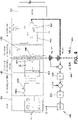
- a known WPT system (100) for an EV (120) is shown in figure 1 , where the basic functional blocks for inductive charging are shared between a ground assembly (GA) (101) and a vehicle assembly (VA) (102).
- the GA (101) of the WPT system (100) comprises an AC/DC converter (104) with power factor correction (PFC) that converts the single or three phase power source (103) to a regulated DC power source.
- the GA (101) of the WPT system (100) also comprises a DC to high frequency (HF) AC converter (105) that generates a square wave voltage with a nearly constant frequency and duty cycles.
- the GA (101) comprises a primary compensation circuit (106) which is a passive circuit network that compensates the transmitting coil inductance in order to reduce the amount of reactive power delivered by the DC to HF AC converter (105).
- the WPT system (100) comprises an inductive charging coil assembly (112) comprising a transmitting GA coil (107) in the ground side, GA (101) and a receiving VA coil (108) located at the vehicle side, VA (102).
- the VA (102) comprises a secondary compensation circuit (109) which is a passive circuit network that compensates the receiving coil inductance in order to maximize the transferred power at electrical resonance.
- the VA (102) comprises an AC/DC Rectifier (110) and/or a DC/DC battery charger (205) (shown in figure 2 )(that may or may not include battery charging algorithms/charging strategy) and the high voltage battery (111).
- the charging of the high voltage battery (111) can potentially be handled by both assemblies the GA (101) and the VA (102) of the WPT system (100), which design can determine an optimal WPT architecture.
- the VA inductive charging of the WPT systems is designed without considering the potential existing conductive charger in the EV. Therefore the charging modules in the WPT are not optimized in terms of cost, volume and weight, because some of the basic functionalities of the charging modules in the VA (102) are likely to be duplicated in the conductive and inductive charging stages of the EV (120).
- FIG 2 shows again, the WPT system (100) in combination with a conductive charging stage OBC (200) in the EV (120).
- the WPT system (100) comprises the GA (101) with the AC/DC converter (104) with power factor correction (PFC) that converts the three phase power source (103) to a regulated DC power source, the HF AC converter (105) that generates a square wave voltage, the primary compensation circuit (106) to compensate the transmitting coil inductance and the transmitting coil (107).
- PFC power factor correction
- the VA (102) of the WPT system (100) comprises the receiving VA coil (108) located at the vehicle side of the inductive charging coil assembly (112), the secondary compensation circuit (109) to compensate the receiving coil inductance, the AC/DC Rectifier (110), a DC link capacitor (204) and a DC/DC battery charger (205).
- FIG 2 shows the OBC (200) for conductive charging of the EV (120).
- the OBC (200) of the VA (102) comprises a three phase PFC stage (201) for the three phase power source (103), a DC link comprising a DC link capacitor (202) and an isolated DC/DC battery charger (203).
- a battery charging system that uses inductive and conductive charging but avoids at least the aforementioned duplicities to reduce volume, weight and cost of the vehicle assembly of the EV is desired.
- US2017279309A1 relates to a primary coil circuit of a ground assembly for wirelessly transferring power to a secondary coil includes: a primary coil magnetically coupled to the secondary coil and having a first terminal and a second terminal; a second capacitor having a first terminal and a second terminal connected to the first terminal of the primary coil; a first inductor having a first terminal coupled to a first input terminal of a power source and a second terminal coupled to the first terminal of the second capacitor; and a first capacitor having a first terminal coupled commonly to the second terminal of the first inductor and the first terminal of the second capacitor and a second terminal coupled commonly to the second terminal of the primary coil and a second input terminal of the power source.
- This invention deals with a wireless power transfer (WPT) system that can be integrated with an already existing conductive on-board battery charger (OBC) for electric vehicles.
- WPT wireless power transfer
- OBC conductive on-board battery charger
- the invention has the potential of sharing the conductive on-board charger modules with the WPT system, thus reducing volume, weight and cost of the vehicle assembly.
- This invention proposes a WPT architecture including the associated power converter topologies with proposed compensation and control strategies that allow integrating the WPT system with charging modules of an already existing conductive charging system in the EV, thus optimizing the EV volume, weight and cost.
- the WPT system comprises a GA and a VA.
- the GA comprises a GA transmitter coil and the VA comprises a VA receiver coil magnetically coupled to the GA transmitter coil.
- This WPT system can correspond to figures 3 and 4 .
- the WPT comprises a compensation strategy.
- the compensation strategy comprises a parallel-series compensation network that permits obtaining a voltage V VA in the VA receiver coil which amplitude is proportional to an effective current I p_rms flowing through the GA transmitter coil.
- a compensation network is shown in figures 5 and 6 .
- the voltage V VA in the VA receiver coil can be converted into a continuous voltage with a rectifier comprised in the VA of the EV. Hence, a continuous V dc_VA of the voltage source V VA is obtained in the VA receiver coil of the WPT.
- the WPT comprises a control strategy stage to adjust the continuous voltage V dc_VA in order to reach a reference DC link voltage.
- the control strategy stage comprises two nested control loops: a voltage control loop receiving as inputs the continuous V dc_VA and the reference DC link voltage and a current control loop receiving as inputs the current I p_rms and the output of the voltage control loop.
- the reference DC link voltage is the required voltage in the DC link of the conductive charger of the EV.
- the DC link of the conductive charger of the EV can be regulated with the adjusted V dc_VA during an inductive charging process of the EV. Therefore, upon the use of the proposed compensation and control strategies, the proposed WPT can use the battery charging modules/DC link of the conductive charger during an inductive charging process of the EV and hence, duplicities in the vehicle assembly can be avoided.
- the GA of the WPT can comprise a DC-to-AC converter that converts a DC source to a square wave voltage source.
- a duty cycle of the DC-to-AC converter may vary depending upon a control command received from the control strategy stage to obtain the adjusted V dc_VA .
- the WPT comprises a DC blocking and impedance matching network (IMN) stage that comprises a capacitor Cc for blocking DC current that may saturate an IMN transformer.
- An inductor Lc can convert the square wave voltage source from the DC-to-AC converter to a current source.
- the IMN transformer can adapt the impedance and voltage levels to values required by the GA coil and the VA coil in the WPT.
- the WPT comprises a GA and a VA.
- the GA comprises a GA transmitter coil.
- the VA comprises a VA receiver coil magnetically coupled to the GA transmitter coil.
- This WPT also comprises a compensation strategy that comprises a parallel-series compensation network to obtain a voltage V VA in the VA receiver coil proportional to an effective current I p_rms in the GA transmitter coil.
- the WPT also comprises a control strategy stage to adjust V dc_VA based on the reference DC link voltage.
- the reference DC link voltage is the required voltage in the DC link of the conductive charger of the EV.
- the control strategy stage comprises two nested control loops: a voltage control loop receiving the V dc_VA and the reference DC link voltage as inputs and a current control loop receiving the current I p_rms and an output from the voltage control loop.
- a power factor correction (PFC) stage of a conductive charger of the EV can be supplied with V VA during an inductive charging process of the EV to obtain a continuous V dc_VA .
- the continuous V dc_VA can be used to regulate a DC link of the conductive charger of the EV. Therefore, the proposed second example of WPT uses the battery charging modules/DC link of the conductive charger during an inductive charging process. Furthermore, this WPT also uses the PFC of the conductive charger as a rectifier to obtain the continuous V dc_VA . Hence, DC charging stages of a conventional WPT are no longer needed with the proposed WPT.
- the WPT of the second aspect according to the present invention can correspond to the embodiment shown in figure 7 .
- WPT comprises the DC-to-AC converter regulated with a control command of the control strategy stage to obtain the adjusted V dc_VA and a DC blocking and impedance matching network (IMN).
- INN DC blocking and impedance matching network
- an electrical vehicle that comprises a conductive charging stage having a DC link and the proposed WPT.
- a method for charging an EV with a WPT system comprising a GA and a VA
- the method comprises a step for applying an effective current I p_rms to a GA transmitter coil of the WPT, a second step for obtaining a voltage V VA in a VA receiver coil of the WPT proportional to the I p_rms , a third step for obtaining a continuous voltage V dc_VA in the VA of the WPT, a fourth step for adjusting V dc_VA to reach a reference DC link voltage value, a fifth step for regulating a DC link of a conductive charging of the EV with the adjusted V dc_VA .
- This method may be performed by the WTP according to the first WPT described in the present disclosure.
- a method for charging an EV with a WPT system comprising a GA and a VA
- the method comprises a first step for applying a effective current I p_rms to a GA transmitter coil of the WPT, a second step for obtaining a voltage V VA in a VA receiver coil of the WPT proportional to the I p_rms , a third step for adjusting V dc_VA to reach a reference DC link voltage, a fourth step for supplying a PFC of conductive charger of the EV with the V VA to obtain a continuous adjusted V dc_VA , and a fifth step for regulating a DC link of the conductive charging of the EV with the continuous adjusted V dc_VA .
- This method may be performed by the second WTP described in the present disclosure.
- FIG 3 shows a first example of a WPT system (300) according to the present invention in combination with a conductive charging stage that comprises the OBC (200) with the DC link capacitor (202) for an EV.
- the WPT system (300) comprises a GA (301) and a VA (302) for inductive charging of the EV.
- the EV comprises an OBC (200) for conductive charging as the one shown in figure 2 .
- the WPT system (300) comprises an inductive charging coil assembly (312) comprising a transmitting coil (307) in the GA (301) and a receiving coil (308) in the VA (302).
- the GA (301) of the WPT system (300) comprises an AC/DC converter (304) with power factor correction (PFC) that converts the three phase power source (303) to a regulated DC power source.
- the GA (301) of the WPT system (300) comprises an AC converter (305) generates a square wave voltage with a nearly constant frequency and duty cycles.
- the WPT system (300) further comprises a compensation circuit having a primary compensation circuit (306) for the GA (301) and a secondary compensation circuit (309) for the VA (302).
- the compensation circuit is a parallel-series compensation network used to achieve a proposed compensation strategy according to the present invention.
- the proposed compensation strategy permits the inductive charging of the EV in the VA (302) to take advantage of the conductive battery charger by regulating the DC link voltage of the DC link capacitor (202) in the OBC (200).
- the compensation circuit (306), (309) permits the receiving coil (308) to behave as a voltage source.
- a voltage V VA is generated in the VA receiver coil (308) having an amplitude proportional to an effective current I p_rms in the GA transmitting coil (307).
- a preferred parallel-series compensation network is shown in figure 5 .
- the VA (302) of the WPT system (300) comprises a secondary compensation circuit (309) as part of the parallel-series compensation network which causes the receiving coil (308) of the coil assembly (312) to behave as a voltage source.
- the VA (302) of the WTP system (300) lacks the DC link capacitor and the DC/DC battery charger previously shown in figure 2 .
- the output of the HF rectifier (310) can be loaded in the DC link capacitor (202).
- the DC link capacitor (202) and the DC/DC battery charger (203) of the OBC (200) can be shared between the conductive stage OBC (200) and the VA (302) of the WPT system (300). Therefore, the proposed WPT system (300) avoids duplicities of the charging modules/DC links in the EV (120).
- Figure 4 shows a GA (401) and VA (401) wireless charging stages of a more detailed example of a WPT (400) according to the present disclosure.
- Figure 4 also shows the control strategy stage (445) used to obtain a desired voltage to regulate a DC link/battery charger in a conventional conductive charger of an EV.
- the GA (401) comprises a DC-to-AC converter (404) that would correspond to the AC converter (305) in figure 3 and which converts a DC source V dc_GA to a square wave voltage source which main frequency depends upon an applicable technical standard, e.g. SAE standard (e.g. 81.38kHz to 90kHz), and which duty cycle may vary depending upon regulation circuit input command from the control strategy stage (445).
- the DC-to-AC converter (404) can be designed to minimize switching loses by means of zero voltage switching (ZVS) or zero current switching (ZCS) techniques.
- the GA (401) comprises DC blocking and Impedance Matching Network (IMN) stage (405) that includes a capacitor Cc (405a) for blocking DC current that may saturate the IMN transformer.
- An inductor Lc (405b) converts the square wave voltage source to a current source and an IMN transformer adapts the impedance and voltage levels to values required by the WPT coils (407), (408).
- the GA (401) comprises a GA coil Lp (407) and a primary compensating network (406).
- the VA (402) comprises a VA coil Ls (408) and a secondary compensating network (409).
- the compensation network (406), (409) is a parallel-series compensation circuit.
- the parallel-series compensation circuit advantageously permits to generate a voltage source V VA at the VA coil Ls (408) which amplitude depends upon the effective current I p_rms flowing through the GA coil Lp (407).
- the parallel-series compensation circuit permits regulating the DC link voltage by controlling the GA coil current I p_rms in the GA (401).
- the GA coil Lp (407) transfers energy from the GA (401) to the VA (402).
- the compensating network (406) allows the reactive power to be locally provided (i.e. the DC-to-AC converter (404) delivers only the active power).
- the VA coil Ls (408) is magnetically coupled with the GA coil Lp (407) and receives the energy transferred wirelessly from the GA coil Lp (407) which is maximized.
- the VA (402) comprises a HF rectifier (410).
- the HF rectifier (410) converts the high frequency signal across the VA coil to DC.
- Figure 4 also shows a DC link capacitor Cdc (420) of the conductive charging of the EV.
- the WPT (400) also shows a block diagram of the proposed control strategy stage (445) used to obtain a desired continuous voltage that regulates the DC link/battery charger in the conductive charger of the EV.
- the control strategy stage (445) is composed of 2 nested control loops based on the regulation of the voltage source V dc_VA and the GA coil current I p_rms .
- the control strategy stage comprises two PI regulators (450), (455) for the voltage and current control.
- V da_VA* represents the reference DC link voltage, i.e. the required DC link voltage in the DC link.
- V dc_VA is the actual DC link voltage, i.e. the voltage measured in real time.
- V dc_VA is the DC value of the voltage V VA at the VA coil Ls (408) after rectification.
- the WPT (400) comprises wireless communication means between the VA (402) and the GA (401).
- the reference DC link voltage V da_VA* and the actual DC link voltage V dc_VA can be sent from the VA (402) to the GA (401) wirelessly by using online communication as e.g. WIFI and/or offline communication as e.g. Bluetooth, NFC or the like.
- the PI regulators (450), (455) can make the actual DC link voltage V dc_VA equal to the reference DC link voltage V da_VA* . Therefore the subtraction of V dc_VA and V da_VA* is 0 at steady state and the DC link of the conductive charger of the EV can be regulated with the adjusted V dc_VA during an inductive charging process of the EV.
- the control strategy stage (445) can command the DC-to-AC converter (404) to regulate I p_rms to obtain a V dc_VA equal to V da_VA *.
- FIG. 5 shows a parallel-series compensation circuit (500) that can be used in the proposed WPT's according to the present invention.
- Figure 6 explains the electrical behaviour of the parallel-series compensation circuit (500).
- a voltage source in series with the coil inductance is shown, which models more accurately the behaviour of the coupled coils (the parasitic resistance has been neglected in this figure).
- the compensation of the VA coil makes L s to disappear from the model, thus leaving just the voltage source, which is proportional to the frequency, the coupling term M and the primary coil current I p .
- FIG. 7 shows an alternative example of a WPT (700) according to the present invention.
- the GA (701) of the WPT (700) comprises an AC/DC converter (704) with power factor correction (PFC) that converts the three phase power source (103) to a regulated DC power source.
- the GA (701) of the WPT (700) comprises an AC converter (705) that generates a square wave voltage with a nearly constant frequency and duty cycles.
- the WPT (700) comprises an inductive charging coil assembly (712) comprising a transmitting coil (707) in the GA (701) and a receiving coil (708) in the VA (713).
- the inductive charging coil assembly (712) in the GA (701) comprises a GA coil (707) and a primary compensating network (706).
- the VA (702) comprises the VA coil (708) and a secondary compensating network (709).
- the compensation network (706), (709) is also a parallel-series compensation circuit.
- the parallel-series compensation circuit advantageously permits to generate a voltage source at the VA coil (708) which amplitude depends upon the effective current flowing through the GA coil (707).
- FIG 7 also shows the conductive charging stage OBC (200) for conductive charging of the EV.
- the OBC (200) of the VA (702) comprises the three phase PFC stage (201) for the three phase power source (103), the DC link comprising the DC link capacitor (202) and the isolated DC/DC battery charger (203).
- the output of the VA compensation network (709) is connected to the input of the conductive charger three phase PFC stage (201) in the conductive charging OBC (200).
- the three phase PFC stage (201) can be composed of 3 half bridges based on MOSFETs (each of them including a parasitic body diode in parallel)
- the three phase PFC stage (201) stage can be used as a simple rectifier in order to obtain an adjusted continuous voltage (V dc_VA ) that can be used to regulate the DC link of the conductive charger of the EV during an inductive charging process of the EV, thus affording the dedicated rectifier shown in the original solution as well as the DC link.
Description
- The present invention refers to wireless power transfer systems for electric vehicles (EV).
- Wireless power transfer (WPT) using magnetic resonance is the technology which could set humans free from the annoying wires. In fact, the WPT adopts the same basic theory which has already been developed for at least 30 years with the term inductive power transfer. WPT technology has been developing rapidly in recent years. At kilowatts power level, the transfer distance increases from several millimeters to several hundred millimeters with a grid to load efficiency above 90%. The advances make the WPT very attractive to the electric vehicle (EV) charging applications in both stationary and dynamic charging scenarios. By introducing WPT in EVs, the obstacles of charging time, range, and cost can be easily mitigated and battery technology is not as relevant in the EVs market.
- Conventionally, in power conversion, when AC is converted to low voltage DC, or AC from one frequency to another, the AC is usually rectified and smoothed to obtain a fixed voltage at fixed frequency. Once this is accomplished, the power is then routed to an inverter to obtain the final output with variable voltage and variable frequency. The DC voltage that is fed into the inverter is called the DC link. As the name implies, the two sources are linked together with a filter capacitor.
- In electric vehicle (EV) applications, the DC link capacitor is used as a load-balancing energy storage device. The DC link capacitor may be placed between the DC battery and the AC, i.e. the load side of the voltage inverter. The capacitor is placed parallel to the battery and to a DC-to-DC battery charger, maintaining a solid voltage across the inverter. The DC link capacitor helps protecting the inverter network from momentary voltage spikes, surges and EMI.
- A known WPT system (100) for an EV (120) is shown in
figure 1 , where the basic functional blocks for inductive charging are shared between a ground assembly (GA) (101) and a vehicle assembly (VA) (102). - The GA (101) of the WPT system (100) comprises an AC/DC converter (104) with power factor correction (PFC) that converts the single or three phase power source (103) to a regulated DC power source. The GA (101) of the WPT system (100) also comprises a DC to high frequency (HF) AC converter (105) that generates a square wave voltage with a nearly constant frequency and duty cycles. The GA (101) comprises a primary compensation circuit (106) which is a passive circuit network that compensates the transmitting coil inductance in order to reduce the amount of reactive power delivered by the DC to HF AC converter (105).
- The WPT system (100) comprises an inductive charging coil assembly (112) comprising a transmitting GA coil (107) in the ground side, GA (101) and a receiving VA coil (108) located at the vehicle side, VA (102).
- The VA (102) comprises a secondary compensation circuit (109) which is a passive circuit network that compensates the receiving coil inductance in order to maximize the transferred power at electrical resonance. The VA (102) comprises an AC/DC Rectifier (110) and/or a DC/DC battery charger (205) (shown in
figure 2 )(that may or may not include battery charging algorithms/charging strategy) and the high voltage battery (111). - The charging of the high voltage battery (111) can potentially be handled by both assemblies the GA (101) and the VA (102) of the WPT system (100), which design can determine an optimal WPT architecture.
- Typically, the VA inductive charging of the WPT systems is designed without considering the potential existing conductive charger in the EV. Therefore the charging modules in the WPT are not optimized in terms of cost, volume and weight, because some of the basic functionalities of the charging modules in the VA (102) are likely to be duplicated in the conductive and inductive charging stages of the EV (120).
- For instance, existing systems elements of the inductive charger of the VA as e.g. a current-doubler rectifier, an interleaved secondary control and/or an output filter stages may not be shared with the conductive charger of the VA. In these systems, it is likely that a conductive on-board charger (OBC) is connected in parallel to the battery duplicating the functionality of the aforementioned stages as shown in
figure 2 that shows the conductive charging stage of the EV (120). -
Figure 2 shows again, the WPT system (100) in combination with a conductive charging stage OBC (200) in the EV (120). The WPT system (100) comprises the GA (101) with the AC/DC converter (104) with power factor correction (PFC) that converts the three phase power source (103) to a regulated DC power source, the HF AC converter (105) that generates a square wave voltage, the primary compensation circuit (106) to compensate the transmitting coil inductance and the transmitting coil (107). - The VA (102) of the WPT system (100) comprises the receiving VA coil (108) located at the vehicle side of the inductive charging coil assembly (112), the secondary compensation circuit (109) to compensate the receiving coil inductance, the AC/DC Rectifier (110), a DC link capacitor (204) and a DC/DC battery charger (205).
-
Figure 2 shows the OBC (200) for conductive charging of the EV (120). The OBC (200) of the VA (102) comprises a three phase PFC stage (201) for the three phase power source (103), a DC link comprising a DC link capacitor (202) and an isolated DC/DC battery charger (203). - Hence, it can be seen from
figure 2 that the DC link capacitors (204) and (202) of the inductive VA (102) and the OBC (200), as well as the DC/DC battery chargers (205) and (203) are duplicated. - Therefore, a battery charging system that uses inductive and conductive charging but avoids at least the aforementioned duplicities to reduce volume, weight and cost of the vehicle assembly of the EV is desired.
-
US2017279309A1 relates to a primary coil circuit of a ground assembly for wirelessly transferring power to a secondary coil includes: a primary coil magnetically coupled to the secondary coil and having a first terminal and a second terminal; a second capacitor having a first terminal and a second terminal connected to the first terminal of the primary coil; a first inductor having a first terminal coupled to a first input terminal of a power source and a second terminal coupled to the first terminal of the second capacitor; and a first capacitor having a first terminal coupled commonly to the second terminal of the first inductor and the first terminal of the second capacitor and a second terminal coupled commonly to the second terminal of the primary coil and a second input terminal of the power source. - The document
US2014/340027 discloses wireless power systems according to the preamble of theclaims 1 and 6. - This invention deals with a wireless power transfer (WPT) system that can be integrated with an already existing conductive on-board battery charger (OBC) for electric vehicles. The invention has the potential of sharing the conductive on-board charger modules with the WPT system, thus reducing volume, weight and cost of the vehicle assembly.
- This invention proposes a WPT architecture including the associated power converter topologies with proposed compensation and control strategies that allow integrating the WPT system with charging modules of an already existing conductive charging system in the EV, thus optimizing the EV volume, weight and cost.
- In a first aspect, it is proposed an example of a WPT system for an EV according to the present invention. The WPT system comprises a GA and a VA. The GA comprises a GA transmitter coil and the VA comprises a VA receiver coil magnetically coupled to the GA transmitter coil. This WPT system can correspond to
figures 3 and4 . - The WPT comprises a compensation strategy. The compensation strategy comprises a parallel-series compensation network that permits obtaining a voltage VVA in the VA receiver coil which amplitude is proportional to an effective current Ip_rms flowing through the GA transmitter coil. A compensation network is shown in
figures 5 and 6 . - The voltage VVA in the VA receiver coil can be converted into a continuous voltage with a rectifier comprised in the VA of the EV. Hence, a continuous Vdc_VA of the voltage source VVA is obtained in the VA receiver coil of the WPT.
- The WPT comprises a control strategy stage to adjust the continuous voltage Vdc_VA in order to reach a reference DC link voltage. For this action, the control strategy stage comprises two nested control loops: a voltage control loop receiving as inputs the continuous Vdc_VA and the reference DC link voltage and a current control loop receiving as inputs the current Ip_rms and the output of the voltage control loop. The reference DC link voltage is the required voltage in the DC link of the conductive charger of the EV.
- Hence, the DC link of the conductive charger of the EV can be regulated with the adjusted Vdc_VA during an inductive charging process of the EV. Therefore, upon the use of the proposed compensation and control strategies, the proposed WPT can use the battery charging modules/DC link of the conductive charger during an inductive charging process of the EV and hence, duplicities in the vehicle assembly can be avoided.
- The GA of the WPT can comprise a DC-to-AC converter that converts a DC source to a square wave voltage source. A duty cycle of the DC-to-AC converter may vary depending upon a control command received from the control strategy stage to obtain the adjusted Vdc_VA .
- Additionally, the WPT comprises a DC blocking and impedance matching network (IMN) stage that comprises a capacitor Cc for blocking DC current that may saturate an IMN transformer. An inductor Lc can convert the square wave voltage source from the DC-to-AC converter to a current source. The IMN transformer can adapt the impedance and voltage levels to values required by the GA coil and the VA coil in the WPT.
- In a second aspect, it is proposed another example of a WPT system for an EV. The WPT comprises a GA and a VA. The GA comprises a GA transmitter coil. The VA comprises a VA receiver coil magnetically coupled to the GA transmitter coil.
- This WPT also comprises a compensation strategy that comprises a parallel-series compensation network to obtain a voltage VVA in the VA receiver coil proportional to an effective current Ip_rms in the GA transmitter coil.
- The WPT also comprises a control strategy stage to adjust Vdc_VA based on the reference DC link voltage. As in the first WPT, the reference DC link voltage is the required voltage in the DC link of the conductive charger of the EV.
- The control strategy stage comprises two nested control loops: a voltage control loop receiving the Vdc_VA and the reference DC link voltage as inputs and a current control loop receiving the current Ip_rms and an output from the voltage control loop.
- A power factor correction (PFC) stage of a conductive charger of the EV can be supplied with VVA during an inductive charging process of the EV to obtain a continuous Vdc_VA . Hence, the continuous Vdc_VA can be used to regulate a DC link of the conductive charger of the EV. Therefore, the proposed second example of WPT uses the battery charging modules/DC link of the conductive charger during an inductive charging process. Furthermore, this WPT also uses the PFC of the conductive charger as a rectifier to obtain the continuous Vdc_VA . Hence, DC charging stages of a conventional WPT are no longer needed with the proposed WPT. The WPT of the second aspect according to the present invention can correspond to the embodiment shown in
figure 7 . - Similar to the first aspect, WPT comprises the DC-to-AC converter regulated with a control command of the control strategy stage to obtain the adjusted Vdc_VA and a DC blocking and impedance matching network (IMN).
- In a third aspect according to the present invention, it is proposed an electrical vehicle that comprises a conductive charging stage having a DC link and the proposed WPT.
- In a fourth aspect, it is proposed a method for charging an EV with a WPT system according to the present invention, the system comprising a GA and a VA, the method comprises a step for applying an effective current Ip_rms to a GA transmitter coil of the WPT, a second step for obtaining a voltage VVA in a VA receiver coil of the WPT proportional to the Ip_rms, a third step for obtaining a continuous voltage Vdc_VA in the VA of the WPT, a fourth step for adjusting Vdc_VA to reach a reference DC link voltage value, a fifth step for regulating a DC link of a conductive charging of the EV with the adjusted Vdc_VA. This method may be performed by the WTP according to the first WPT described in the present disclosure.
- In a fifth aspect, it is proposed a method for charging an EV with a WPT system, the system comprising a GA and a VA, the method comprises a first step for applying a effective current Ip_rms to a GA transmitter coil of the WPT, a second step for obtaining a voltage VVA in a VA receiver coil of the WPT proportional to the Ip_rms, a third step for adjusting Vdc_VA to reach a reference DC link voltage, a fourth step for supplying a PFC of conductive charger of the EV with the VVA to obtain a continuous adjusted Vdc_VA, and a fifth step for regulating a DC link of the conductive charging of the EV with the continuous adjusted Vdc_VA. This method may be performed by the second WTP described in the present disclosure.
- For a better understanding the above explanation and for the sole purpose of providing an example, some non-limiting drawings are included that schematically depict a practical embodiment.
-
Figure 1 shows a conventional WPT system for an EV. -
Figure 2 shows a conventional WPT system in combination with a conductive charger of an EV. -
Figure 3 shows a first example of a WPT and a conductive charger according to the present invention. -
Figure 4 shows the first example of the WPT according to the present invention. -
Figures 5 and 6 show an example of a parallel-series compensation network. -
Figure 7 shows a second example of a WPT according to the present invention. -
Figure 3 shows a first example of a WPT system (300) according to the present invention in combination with a conductive charging stage that comprises the OBC (200) with the DC link capacitor (202) for an EV. The WPT system (300) comprises a GA (301) and a VA (302) for inductive charging of the EV. Furthermore, the EV comprises an OBC (200) for conductive charging as the one shown infigure 2 . - The WPT system (300) comprises an inductive charging coil assembly (312) comprising a transmitting coil (307) in the GA (301) and a receiving coil (308) in the VA (302).
- The GA (301) of the WPT system (300) comprises an AC/DC converter (304) with power factor correction (PFC) that converts the three phase power source (303) to a regulated DC power source. The GA (301) of the WPT system (300) comprises an AC converter (305) generates a square wave voltage with a nearly constant frequency and duty cycles.
- The WPT system (300) further comprises a compensation circuit having a primary compensation circuit (306) for the GA (301) and a secondary compensation circuit (309) for the VA (302). The compensation circuit is a parallel-series compensation network used to achieve a proposed compensation strategy according to the present invention. The proposed compensation strategy permits the inductive charging of the EV in the VA (302) to take advantage of the conductive battery charger by regulating the DC link voltage of the DC link capacitor (202) in the OBC (200). Hence, the compensation circuit (306), (309) permits the receiving coil (308) to behave as a voltage source. Hence, a voltage VVA is generated in the VA receiver coil (308) having an amplitude proportional to an effective current Ip_rms in the GA transmitting coil (307). A preferred parallel-series compensation network is shown in
figure 5 . - The VA (302) of the WPT system (300) comprises a secondary compensation circuit (309) as part of the parallel-series compensation network which causes the receiving coil (308) of the coil assembly (312) to behave as a voltage source. The VA (302) of the WTP system (300) lacks the DC link capacitor and the DC/DC battery charger previously shown in
figure 2 . The output of the HF rectifier (310) can be loaded in the DC link capacitor (202). Hence, the DC link capacitor (202) and the DC/DC battery charger (203) of the OBC (200) can be shared between the conductive stage OBC (200) and the VA (302) of the WPT system (300). Therefore, the proposed WPT system (300) avoids duplicities of the charging modules/DC links in the EV (120). -
Figure 4 shows a GA (401) and VA (401) wireless charging stages of a more detailed example of a WPT (400) according to the present disclosure.Figure 4 also shows the control strategy stage (445) used to obtain a desired voltage to regulate a DC link/battery charger in a conventional conductive charger of an EV. - The GA (401) comprises a DC-to-AC converter (404) that would correspond to the AC converter (305) in
figure 3 and which converts a DC source Vdc_GA to a square wave voltage source which main frequency depends upon an applicable technical standard, e.g. SAE standard (e.g. 81.38kHz to 90kHz), and which duty cycle may vary depending upon regulation circuit input command from the control strategy stage (445). The DC-to-AC converter (404) can be designed to minimize switching loses by means of zero voltage switching (ZVS) or zero current switching (ZCS) techniques. - The GA (401) comprises DC blocking and Impedance Matching Network (IMN) stage (405) that includes a capacitor Cc (405a) for blocking DC current that may saturate the IMN transformer. An inductor Lc (405b) converts the square wave voltage source to a current source and an IMN transformer adapts the impedance and voltage levels to values required by the WPT coils (407), (408).
- The GA (401) comprises a GA coil Lp (407) and a primary compensating network (406). The VA (402) comprises a VA coil Ls (408) and a secondary compensating network (409). The compensation network (406), (409) is a parallel-series compensation circuit. As previously mentioned, the parallel-series compensation circuit advantageously permits to generate a voltage source VVA at the VA coil Ls (408) which amplitude depends upon the effective current Ip_rms flowing through the GA coil Lp (407). Because the DC link voltage of the conductive charging in the DC/DC battery charge (403) shall be regulated within certain boundaries to ensure the proper operation of the on-board DC-to-DC battery charger, the parallel-series compensation circuit permits regulating the DC link voltage by controlling the GA coil current Ip_rms in the GA (401).
- Hence, the GA coil Lp (407) transfers energy from the GA (401) to the VA (402). The compensating network (406) allows the reactive power to be locally provided (i.e. the DC-to-AC converter (404) delivers only the active power). The VA coil Ls (408) is magnetically coupled with the GA coil Lp (407) and receives the energy transferred wirelessly from the GA coil Lp (407) which is maximized.
- The VA (402) comprises a HF rectifier (410). The HF rectifier (410) converts the high frequency signal across the VA coil to DC.
Figure 4 also shows a DC link capacitor Cdc (420) of the conductive charging of the EV. The WPT (400) also shows a block diagram of the proposed control strategy stage (445) used to obtain a desired continuous voltage that regulates the DC link/battery charger in the conductive charger of the EV. - As shown in
figure 4 , the control strategy stage (445) is composed of 2 nested control loops based on the regulation of the voltage source Vdc_VA and the GA coil current Ip_rms . For this particular implementation, the control strategy stage comprises two PI regulators (450), (455) for the voltage and current control. - Vda_VA* represents the reference DC link voltage, i.e. the required DC link voltage in the DC link. Vdc_VA is the actual DC link voltage, i.e. the voltage measured in real time. Vdc_VA is the DC value of the voltage VVA at the VA coil Ls (408) after rectification. Furthermore, the WPT (400) comprises wireless communication means between the VA (402) and the GA (401). Hence, the reference DC link voltage Vda_VA* and the actual DC link voltage Vdc_VA can be sent from the VA (402) to the GA (401) wirelessly by using online communication as e.g. WIFI and/or offline communication as e.g. Bluetooth, NFC or the like. After some time (usually in the range of seconds or milliseconds for this application), the PI regulators (450), (455) can make the actual DC link voltage Vdc_VA equal to the reference DC link voltage Vda_VA*. Therefore the subtraction of Vdc_VA and Vda_VA* is 0 at steady state and the DC link of the conductive charger of the EV can be regulated with the adjusted Vdc_VA during an inductive charging process of the EV. Hence, the control strategy stage (445) can command the DC-to-AC converter (404) to regulate Ip_rms to obtain a Vdc_VA equal to Vda_VA*.
-
Figure 5 shows a parallel-series compensation circuit (500) that can be used in the proposed WPT's according to the present invention. The VA coil model in the VA (302) includes a parasitic R2 and an inductor L2. If a capacitor C2 is placed in series with the inductor L2 (compensation network) and its value is properly chosen, the impedance of the series connection of L2 and the capacitor C2 is null at the operating frequency, where the wireless transfer happens at a fixed frequency f = 85 Khz. Interestingly enough, the amplitude of this voltage depends upon the signal frequency which is constant, the coupling term, M which is also constant for a given position of the EV car relative to the GA coil L1, and the GA current Ip_rms. Therefore, this is the electrical relationship between the GA coil current Ip_rms and the VA coil voltage VVA. Therefore, as the inductor L2 is cancelled out with the series capacitor C2, this voltage VVA can be placed directly across the terminals of the HF rectifier (410). -
Figure 6 explains the electrical behaviour of the parallel-series compensation circuit (500). In this figure, a voltage source in series with the coil inductance is shown, which models more accurately the behaviour of the coupled coils (the parasitic resistance has been neglected in this figure). The compensation of the VA coil makes Ls to disappear from the model, thus leaving just the voltage source, which is proportional to the frequency, the coupling term M and the primary coil current Ip. -
Figure 7 shows an alternative example of a WPT (700) according to the present invention. - Similarly, the GA (701) of the WPT (700) comprises an AC/DC converter (704) with power factor correction (PFC) that converts the three phase power source (103) to a regulated DC power source. The GA (701) of the WPT (700) comprises an AC converter (705) that generates a square wave voltage with a nearly constant frequency and duty cycles.
- The WPT (700) comprises an inductive charging coil assembly (712) comprising a transmitting coil (707) in the GA (701) and a receiving coil (708) in the VA (713).
- The inductive charging coil assembly (712) in the GA (701) comprises a GA coil (707) and a primary compensating network (706). The VA (702) comprises the VA coil (708) and a secondary compensating network (709). The compensation network (706), (709) is also a parallel-series compensation circuit. As previously mentioned, the parallel-series compensation circuit advantageously permits to generate a voltage source at the VA coil (708) which amplitude depends upon the effective current flowing through the GA coil (707).
-
Figure 7 also shows the conductive charging stage OBC (200) for conductive charging of the EV. The OBC (200) of the VA (702) comprises the three phase PFC stage (201) for the three phase power source (103), the DC link comprising the DC link capacitor (202) and the isolated DC/DC battery charger (203). - An alternative solution is shown in
Figure 7 , the output of the VA compensation network (709) is connected to the input of the conductive charger three phase PFC stage (201) in the conductive charging OBC (200). Because the three phase PFC stage (201) can be composed of 3 half bridges based on MOSFETs (each of them including a parasitic body diode in parallel), the three phase PFC stage (201) stage can be used as a simple rectifier in order to obtain an adjusted continuous voltage (Vdc_VA) that can be used to regulate the DC link of the conductive charger of the EV during an inductive charging process of the EV, thus affording the dedicated rectifier shown in the original solution as well as the DC link. - Even though reference has been made to a specific embodiment of the invention, it is obvious for a person skilled in the art that the WPT architectures described herein are susceptible to numerous variations and modifications, and that all the details mentioned can be substituted for other technically equivalent ones within the scope of protection defined by the attached claims.
Claims (14)
- A wireless power transfer, WPT, (400) system for an electrical vehicle, EV, the system comprising a ground assembly, GA, (401) and a vehicle assembly, VA (402), and a conductive charger with a DC link, and a rectifier (410) in the VA (402) to obtain a continuous voltage Vdc_VA, the GA (401) comprising a GA transmitter coil (407), the VA (402) comprising a VA receiver coil (408) magnetically coupled to the GA transmitter coil (407), characterized in that the WPT (400) system comprises:a compensation strategy stage (406) (409) that comprises a parallel-series compensation network to obtain a voltage VvA in the VA receiver coil (408) proportional to an effective current Ip_rms in the GA transmitter coil (407);a control strategy stage (445) with a voltage control loop (450) receiving as inputs the continuous voltage Vdc_VA and a reference DC link voltage and a current control loop (455) receiving as input the current flowing through the GA transmitter coil Ip_rms and an output from the voltage control loop,wherein the control strategy stage (445) is configured to provide a control command to regulate voltage in the VA (402) to adjust the continuous voltage Vdc_VA based on the reference DC link voltage, andwherein the DC link of the conductive charger of the EV connected to the rectifier (410) is configured to be regulated with the adjusted continuous voltage Vdc_VA during an inductive charging process of the EV.
- The WPT system (400) for an EV according to claim 1, wherein the GA (401) comprises a DC-to-AC converter (404) regulated with the control command of the control strategy stage (445).
- The WPT system (400) for an EV according to any of the preceding claims, wherein the GA (401) comprises an AC/DC converter (304) with power factor correction, PFC.
- The WPT system (400) for an EV according to any of the preceding claims, wherein the GA (401) comprises a DC blocking and impedance matching network, IMN.
- The WPT system (400) for an EV according to any of the preceding claims, wherein the GA (401) and the VA (402) comprise wireless communication means for at least transmitting the continuous voltage Vdc_VA and the reference DC link voltage from the VA(402) to the GA (401).
- A WPT system (700) system for an EV comprising a conductive charger with a DC link, a GA (701) and a VA (702), the GA (701) comprising a GA transmitter coil (707), the VA (702) comprising a VA receiver coil (708) magnetically coupled to the GA transmitter coil (707), wherein a PFC stage of a conductive charger of the EV is connected with the voltage VVA during an inductive charging process of the EV, characterized in that the WPT (700) comprises:a compensation strategy (706) (709) that comprises a parallel-series compensation network to obtain a voltage VVA in the VA receiver coil (709) proportional to an effective current Ip_rms in the GA transmitter coil (707); anda control strategy stage (445) with a voltage control loop (450) receiving as inputs the continuous voltage Vdc_VA and a reference DC link voltage and a current control loop (455) receiving as input the current flowing through the GA transmitter coil Ip_rm, and an output from the voltage control loop,wherein the control strategy stage (445) is configured to provide a control command to regulate voltage in the VA (702) to adjust a continuous voltage Vdc_VA based on the reference DC link voltage,wherein the Vdc_VA represents the voltage measured at the DC link of the conductive charger of the EV.
- The WPT system (700) for an EV according to claim 5, wherein the GA (701) comprises a DC-to-AC converter (705) regulated with a control command of the control strategy stage (445).
- The WPT system (700) for an EV according to claims 5 and 6, wherein the GA (701) comprises an AC/DC converter (704) with PFC.
- The WPT system (700) for an EV according to claims 5 to 7, wherein the GA (701) comprises a DC blocking and impedance matching network (IMN).
- The WPT system (700) for an EV according to claims 6 to 9, wherein the GA (701) and the VA (702) comprise wireless communication means for transmitting the continuous voltage Vdc_VA and the reference DC link voltage from the VA(402) to the GA (401).
- An electric vehicle, comprising:a conductive charging stage (200) having a DC link; andthe WPT system (400, 700) according to any of the claims 1 to 10,wherein the WPT system (300, 700) regulates the DC link of the conductive charging stage (200).
- A method for charging an EV with a WPT system according to claim 1 , the method comprising:applying an effective current Ip_rms to a GA transmitter coil of the WPT,obtaining a voltage VVA in a VA receiver coil of the WPT proportional to the Ip_rms;obtaining a continuous voltage Vdc_VA in the VA of the WPT;adjusting the continuous voltage Vdc_VA based on a reference DC link voltage;regulating a DC link of a conductive charging of the EV with the adjusted continuous voltage Vdc_VA.,wherein the Vdc_VA represents the voltage measured at the DC link of the conductive charger of the EV,wherein the DC link of the conductive charging of the EV is connected to a rectifier.
- A method for charging an EV, with a WPT system according to claim 6 , the method comprising:applying a effective current Ip_rms to a GA transmitter coil of the WPT,obtaining a voltage VvA in a VA receiver coil of the WPT proportional to the Ip_rms;supplying a PFC stage of a conductive charger of the EV with the voltage VVA;obtaining an adjusted continuous voltage Vdc_VA;adjusting the continuous voltage Vdc_VA based on a reference DC link voltage;regulating a DC link of the conductive charging of the EV with the adjusted continuous voltage Vdc_VA,wherein the Vdc_VA represents the voltage measured at the DC link of the conductive charger of the EV, andwherein the DC link of the conductive charging of the EV is connected to a rectifier.
- The method according to claims 11 or 12, further comprising:
transmitting the continuous voltage Vdc_VA and the reference DC link voltage from the VA to the GA of the WPT systems (400, 700).
Priority Applications (5)
| Application Number | Priority Date | Filing Date | Title |
|---|---|---|---|
| ES19382083T ES2934079T3 (en) | 2019-02-05 | 2019-02-05 | Wireless power transfer systems for electric vehicles |
| EP19382083.4A EP3694079B1 (en) | 2019-02-05 | 2019-02-05 | Wireless power transfer systems for electric vehicles |
| JP2020007224A JP2020127353A (en) | 2019-02-05 | 2020-01-21 | Wireless power transfer system for electric vehicle |
| US16/782,056 US20200247250A1 (en) | 2019-02-05 | 2020-02-04 | Wireless power transfer systems for electric vehicles |
| CN202010079820.XA CN111516515A (en) | 2019-02-05 | 2020-02-04 | Wireless power transmission system for electric vehicle |
Applications Claiming Priority (1)
| Application Number | Priority Date | Filing Date | Title |
|---|---|---|---|
| EP19382083.4A EP3694079B1 (en) | 2019-02-05 | 2019-02-05 | Wireless power transfer systems for electric vehicles |
Publications (2)
| Publication Number | Publication Date |
|---|---|
| EP3694079A1 EP3694079A1 (en) | 2020-08-12 |
| EP3694079B1 true EP3694079B1 (en) | 2022-11-30 |
Family
ID=65529612
Family Applications (1)
| Application Number | Title | Priority Date | Filing Date |
|---|---|---|---|
| EP19382083.4A Active EP3694079B1 (en) | 2019-02-05 | 2019-02-05 | Wireless power transfer systems for electric vehicles |
Country Status (5)
| Country | Link |
|---|---|
| US (1) | US20200247250A1 (en) |
| EP (1) | EP3694079B1 (en) |
| JP (1) | JP2020127353A (en) |
| CN (1) | CN111516515A (en) |
| ES (1) | ES2934079T3 (en) |
Families Citing this family (4)
| Publication number | Priority date | Publication date | Assignee | Title |
|---|---|---|---|---|
| US11878600B2 (en) * | 2021-03-31 | 2024-01-23 | Lear Corporation | Vehicle on-board charger with variable DC-link voltage |
| US11949330B2 (en) * | 2021-10-19 | 2024-04-02 | Volvo Car Corporation | Integrated power conversion topology for electric vehicles |
| CN114221535B (en) * | 2021-12-21 | 2023-12-19 | 阳光电源股份有限公司 | Vehicle-mounted charger, DCDC converter and control method |
| WO2024023657A1 (en) | 2022-07-28 | 2024-02-01 | Bluhub Srl | System for the simultaneous wireless charging of light electric vehicles |
Citations (2)
| Publication number | Priority date | Publication date | Assignee | Title |
|---|---|---|---|---|
| US20140340027A1 (en) * | 2013-05-15 | 2014-11-20 | Qualcomm Incorporated | Systems, methods, and apparatus related to electric vehicle wired and wireless charging |
| US20180281608A1 (en) * | 2017-04-04 | 2018-10-04 | GM Global Technology Operations LLC | Inductive and conductive onboard charging systems |
Family Cites Families (5)
| Publication number | Priority date | Publication date | Assignee | Title |
|---|---|---|---|---|
| EP2928038A1 (en) * | 2014-03-31 | 2015-10-07 | ABB Technology AG | Inductive power transfer system and method for operating an inductive power transfer system |
| CN106134029B (en) * | 2014-04-16 | 2018-09-25 | 三菱电机株式会社 | Vehicle charger |
| KR20170110866A (en) * | 2016-03-24 | 2017-10-12 | 현대자동차주식회사 | Primary coil circuit for wireless power transfer and ground assembly and manufacturing method therefor using the same |
| KR102526872B1 (en) * | 2016-11-01 | 2023-04-27 | 현대자동차주식회사 | Wireless power transfer method using field windings and vehicle assembly and electric vehicle using the same |
| US10427532B2 (en) * | 2017-04-05 | 2019-10-01 | Ford Global Technologies, Llc | On-board and wireless vehicle charging systems with shared components |
-
2019
- 2019-02-05 EP EP19382083.4A patent/EP3694079B1/en active Active
- 2019-02-05 ES ES19382083T patent/ES2934079T3/en active Active
-
2020
- 2020-01-21 JP JP2020007224A patent/JP2020127353A/en active Pending
- 2020-02-04 CN CN202010079820.XA patent/CN111516515A/en active Pending
- 2020-02-04 US US16/782,056 patent/US20200247250A1/en not_active Abandoned
Patent Citations (2)
| Publication number | Priority date | Publication date | Assignee | Title |
|---|---|---|---|---|
| US20140340027A1 (en) * | 2013-05-15 | 2014-11-20 | Qualcomm Incorporated | Systems, methods, and apparatus related to electric vehicle wired and wireless charging |
| US20180281608A1 (en) * | 2017-04-04 | 2018-10-04 | GM Global Technology Operations LLC | Inductive and conductive onboard charging systems |
Also Published As
| Publication number | Publication date |
|---|---|
| JP2020127353A (en) | 2020-08-20 |
| ES2934079T3 (en) | 2023-02-16 |
| US20200247250A1 (en) | 2020-08-06 |
| EP3694079A1 (en) | 2020-08-12 |
| CN111516515A (en) | 2020-08-11 |
Similar Documents
| Publication | Publication Date | Title |
|---|---|---|
| EP3694079B1 (en) | Wireless power transfer systems for electric vehicles | |
| KR102226793B1 (en) | How to control the on-board charging device of an electric or hybrid vehicle | |
| Onar et al. | Vehicular integration of wireless power transfer systems and hardware interoperability case studies | |
| US9825473B2 (en) | Contactless power transfer system | |
| Onar et al. | A high-power wireless charging system development and integration for a Toyota RAV4 electric vehicle | |
| WO2016099685A1 (en) | Systems, apparatus and method for adaptive wireless power transfer | |
| CN111016694B (en) | Wireless charging transmitting terminal, receiving terminal, method and system | |
| JP2017175718A (en) | Wireless power transmission system | |
| EP2874268A1 (en) | Power-receiving device and power transfer system | |
| EP2302760A2 (en) | Automatic method for controlling a high-frequency inductive coupling power transfer system | |
| US10298063B2 (en) | Power-supplying device and wireless power supply system | |
| US20210091591A1 (en) | Controlling a wireless power transfer system | |
| CN111740504B (en) | Wireless charging control method and wireless charging system | |
| Chen et al. | Research on bidirectional contactless resonant converter for energy charging between EVs | |
| Azad et al. | A supercapacitor-based converter topology for grid-side power management in dynamic wireless charging systems | |
| US20190299800A1 (en) | Wireless power transmission device and wireless power transmission system | |
| JP2016220293A (en) | Non-contact power transmission device | |
| Jo et al. | Design and Control of the Adjustable Turn-ratio LLC Converter for High-Efficiency Operation of Wired/Wireless Integrated EV Charging System | |
| Somsak et al. | Constant current-voltage with maximum efficiency inductive wireless EV charging control using dual-sides DC converters | |
| CN115280635A (en) | Active impedance control | |
| Maddalena et al. | A straightforward closed-loop wireless power transfer battery charger | |
| CN110932374A (en) | Wireless charging system | |
| EP3467996A1 (en) | Contactless power supply system and contactless power transmission system | |
| Kavimandan et al. | Dual independent control for inductive wireless power transfer | |
| Nguyen et al. | A constant current and constant voltage compensation scheme for wireless charger |
Legal Events
| Date | Code | Title | Description |
|---|---|---|---|
| PUAI | Public reference made under article 153(3) epc to a published international application that has entered the european phase |
Free format text: ORIGINAL CODE: 0009012 |
|
| STAA | Information on the status of an ep patent application or granted ep patent |
Free format text: STATUS: THE APPLICATION HAS BEEN PUBLISHED |
|
| AK | Designated contracting states |
Kind code of ref document: A1 Designated state(s): AL AT BE BG CH CY CZ DE DK EE ES FI FR GB GR HR HU IE IS IT LI LT LU LV MC MK MT NL NO PL PT RO RS SE SI SK SM TR |
|
| AX | Request for extension of the european patent |
Extension state: BA ME |
|
| STAA | Information on the status of an ep patent application or granted ep patent |
Free format text: STATUS: REQUEST FOR EXAMINATION WAS MADE |
|
| STAA | Information on the status of an ep patent application or granted ep patent |
Free format text: STATUS: EXAMINATION IS IN PROGRESS |
|
| 17P | Request for examination filed |
Effective date: 20210211 |
|
| RBV | Designated contracting states (corrected) |
Designated state(s): AL AT BE BG CH CY CZ DE DK EE ES FI FR GB GR HR HU IE IS IT LI LT LU LV MC MK MT NL NO PL PT RO RS SE SI SK SM TR |
|
| 17Q | First examination report despatched |
Effective date: 20210323 |
|
| GRAP | Despatch of communication of intention to grant a patent |
Free format text: ORIGINAL CODE: EPIDOSNIGR1 |
|
| STAA | Information on the status of an ep patent application or granted ep patent |
Free format text: STATUS: GRANT OF PATENT IS INTENDED |
|
| INTG | Intention to grant announced |
Effective date: 20220713 |
|
| GRAS | Grant fee paid |
Free format text: ORIGINAL CODE: EPIDOSNIGR3 |
|
| GRAA | (expected) grant |
Free format text: ORIGINAL CODE: 0009210 |
|
| STAA | Information on the status of an ep patent application or granted ep patent |
Free format text: STATUS: THE PATENT HAS BEEN GRANTED |
|
| AK | Designated contracting states |
Kind code of ref document: B1 Designated state(s): AL AT BE BG CH CY CZ DE DK EE ES FI FR GB GR HR HU IE IS IT LI LT LU LV MC MK MT NL NO PL PT RO RS SE SI SK SM TR |
|
| REG | Reference to a national code |
Ref country code: CH Ref legal event code: EP Ref country code: GB Ref legal event code: FG4D |
|
| REG | Reference to a national code |
Ref country code: AT Ref legal event code: REF Ref document number: 1535439 Country of ref document: AT Kind code of ref document: T Effective date: 20221215 |
|
| REG | Reference to a national code |
Ref country code: IE Ref legal event code: FG4D |
|
| REG | Reference to a national code |
Ref country code: DE Ref legal event code: R096 Ref document number: 602019022502 Country of ref document: DE |
|
| REG | Reference to a national code |
Ref country code: ES Ref legal event code: FG2A Ref document number: 2934079 Country of ref document: ES Kind code of ref document: T3 Effective date: 20230216 |
|
| REG | Reference to a national code |
Ref country code: LT Ref legal event code: MG9D |
|
| REG | Reference to a national code |
Ref country code: NL Ref legal event code: MP Effective date: 20221130 |
|
| PG25 | Lapsed in a contracting state [announced via postgrant information from national office to epo] |
Ref country code: SE Free format text: LAPSE BECAUSE OF FAILURE TO SUBMIT A TRANSLATION OF THE DESCRIPTION OR TO PAY THE FEE WITHIN THE PRESCRIBED TIME-LIMIT Effective date: 20221130 Ref country code: PT Free format text: LAPSE BECAUSE OF FAILURE TO SUBMIT A TRANSLATION OF THE DESCRIPTION OR TO PAY THE FEE WITHIN THE PRESCRIBED TIME-LIMIT Effective date: 20230331 Ref country code: NO Free format text: LAPSE BECAUSE OF FAILURE TO SUBMIT A TRANSLATION OF THE DESCRIPTION OR TO PAY THE FEE WITHIN THE PRESCRIBED TIME-LIMIT Effective date: 20230228 Ref country code: LT Free format text: LAPSE BECAUSE OF FAILURE TO SUBMIT A TRANSLATION OF THE DESCRIPTION OR TO PAY THE FEE WITHIN THE PRESCRIBED TIME-LIMIT Effective date: 20221130 Ref country code: FI Free format text: LAPSE BECAUSE OF FAILURE TO SUBMIT A TRANSLATION OF THE DESCRIPTION OR TO PAY THE FEE WITHIN THE PRESCRIBED TIME-LIMIT Effective date: 20221130 |
|
| PGFP | Annual fee paid to national office [announced via postgrant information from national office to epo] |
Ref country code: FR Payment date: 20230213 Year of fee payment: 5 Ref country code: ES Payment date: 20230307 Year of fee payment: 5 |
|
| REG | Reference to a national code |
Ref country code: AT Ref legal event code: MK05 Ref document number: 1535439 Country of ref document: AT Kind code of ref document: T Effective date: 20221130 |
|
| PG25 | Lapsed in a contracting state [announced via postgrant information from national office to epo] |
Ref country code: RS Free format text: LAPSE BECAUSE OF FAILURE TO SUBMIT A TRANSLATION OF THE DESCRIPTION OR TO PAY THE FEE WITHIN THE PRESCRIBED TIME-LIMIT Effective date: 20221130 Ref country code: PL Free format text: LAPSE BECAUSE OF FAILURE TO SUBMIT A TRANSLATION OF THE DESCRIPTION OR TO PAY THE FEE WITHIN THE PRESCRIBED TIME-LIMIT Effective date: 20221130 Ref country code: LV Free format text: LAPSE BECAUSE OF FAILURE TO SUBMIT A TRANSLATION OF THE DESCRIPTION OR TO PAY THE FEE WITHIN THE PRESCRIBED TIME-LIMIT Effective date: 20221130 Ref country code: IS Free format text: LAPSE BECAUSE OF FAILURE TO SUBMIT A TRANSLATION OF THE DESCRIPTION OR TO PAY THE FEE WITHIN THE PRESCRIBED TIME-LIMIT Effective date: 20230330 Ref country code: HR Free format text: LAPSE BECAUSE OF FAILURE TO SUBMIT A TRANSLATION OF THE DESCRIPTION OR TO PAY THE FEE WITHIN THE PRESCRIBED TIME-LIMIT Effective date: 20221130 Ref country code: GR Free format text: LAPSE BECAUSE OF FAILURE TO SUBMIT A TRANSLATION OF THE DESCRIPTION OR TO PAY THE FEE WITHIN THE PRESCRIBED TIME-LIMIT Effective date: 20230301 |
|
| PGFP | Annual fee paid to national office [announced via postgrant information from national office to epo] |
Ref country code: GB Payment date: 20230209 Year of fee payment: 5 Ref country code: DE Payment date: 20230216 Year of fee payment: 5 |
|
| PG25 | Lapsed in a contracting state [announced via postgrant information from national office to epo] |
Ref country code: NL Free format text: LAPSE BECAUSE OF FAILURE TO SUBMIT A TRANSLATION OF THE DESCRIPTION OR TO PAY THE FEE WITHIN THE PRESCRIBED TIME-LIMIT Effective date: 20221130 |
|
| PG25 | Lapsed in a contracting state [announced via postgrant information from national office to epo] |
Ref country code: SM Free format text: LAPSE BECAUSE OF FAILURE TO SUBMIT A TRANSLATION OF THE DESCRIPTION OR TO PAY THE FEE WITHIN THE PRESCRIBED TIME-LIMIT Effective date: 20221130 Ref country code: RO Free format text: LAPSE BECAUSE OF FAILURE TO SUBMIT A TRANSLATION OF THE DESCRIPTION OR TO PAY THE FEE WITHIN THE PRESCRIBED TIME-LIMIT Effective date: 20221130 Ref country code: EE Free format text: LAPSE BECAUSE OF FAILURE TO SUBMIT A TRANSLATION OF THE DESCRIPTION OR TO PAY THE FEE WITHIN THE PRESCRIBED TIME-LIMIT Effective date: 20221130 Ref country code: DK Free format text: LAPSE BECAUSE OF FAILURE TO SUBMIT A TRANSLATION OF THE DESCRIPTION OR TO PAY THE FEE WITHIN THE PRESCRIBED TIME-LIMIT Effective date: 20221130 Ref country code: CZ Free format text: LAPSE BECAUSE OF FAILURE TO SUBMIT A TRANSLATION OF THE DESCRIPTION OR TO PAY THE FEE WITHIN THE PRESCRIBED TIME-LIMIT Effective date: 20221130 Ref country code: AT Free format text: LAPSE BECAUSE OF FAILURE TO SUBMIT A TRANSLATION OF THE DESCRIPTION OR TO PAY THE FEE WITHIN THE PRESCRIBED TIME-LIMIT Effective date: 20221130 |
|
| PG25 | Lapsed in a contracting state [announced via postgrant information from national office to epo] |
Ref country code: SK Free format text: LAPSE BECAUSE OF FAILURE TO SUBMIT A TRANSLATION OF THE DESCRIPTION OR TO PAY THE FEE WITHIN THE PRESCRIBED TIME-LIMIT Effective date: 20221130 Ref country code: AL Free format text: LAPSE BECAUSE OF FAILURE TO SUBMIT A TRANSLATION OF THE DESCRIPTION OR TO PAY THE FEE WITHIN THE PRESCRIBED TIME-LIMIT Effective date: 20221130 |
|
| REG | Reference to a national code |
Ref country code: DE Ref legal event code: R097 Ref document number: 602019022502 Country of ref document: DE |
|
| PG25 | Lapsed in a contracting state [announced via postgrant information from national office to epo] |
Ref country code: MC Free format text: LAPSE BECAUSE OF FAILURE TO SUBMIT A TRANSLATION OF THE DESCRIPTION OR TO PAY THE FEE WITHIN THE PRESCRIBED TIME-LIMIT Effective date: 20221130 |
|
| REG | Reference to a national code |
Ref country code: CH Ref legal event code: PL |
|
| PLBE | No opposition filed within time limit |
Free format text: ORIGINAL CODE: 0009261 |
|
| STAA | Information on the status of an ep patent application or granted ep patent |
Free format text: STATUS: NO OPPOSITION FILED WITHIN TIME LIMIT |
|
| REG | Reference to a national code |
Ref country code: BE Ref legal event code: MM Effective date: 20230228 |
|
| PG25 | Lapsed in a contracting state [announced via postgrant information from national office to epo] |
Ref country code: LU Free format text: LAPSE BECAUSE OF NON-PAYMENT OF DUE FEES Effective date: 20230205 Ref country code: LI Free format text: LAPSE BECAUSE OF NON-PAYMENT OF DUE FEES Effective date: 20230228 Ref country code: CH Free format text: LAPSE BECAUSE OF NON-PAYMENT OF DUE FEES Effective date: 20230228 |
|
| 26N | No opposition filed |
Effective date: 20230831 |
|
| PG25 | Lapsed in a contracting state [announced via postgrant information from national office to epo] |
Ref country code: SI Free format text: LAPSE BECAUSE OF FAILURE TO SUBMIT A TRANSLATION OF THE DESCRIPTION OR TO PAY THE FEE WITHIN THE PRESCRIBED TIME-LIMIT Effective date: 20221130 |
|
| REG | Reference to a national code |
Ref country code: IE Ref legal event code: MM4A |
|
| PG25 | Lapsed in a contracting state [announced via postgrant information from national office to epo] |
Ref country code: IE Free format text: LAPSE BECAUSE OF NON-PAYMENT OF DUE FEES Effective date: 20230205 |
|
| PG25 | Lapsed in a contracting state [announced via postgrant information from national office to epo] |
Ref country code: BE Free format text: LAPSE BECAUSE OF NON-PAYMENT OF DUE FEES Effective date: 20230228 |