EP4456332A1 - Wireless communication device and structure - Google Patents
Wireless communication device and structure Download PDFInfo
- Publication number
- EP4456332A1 EP4456332A1 EP22911380.8A EP22911380A EP4456332A1 EP 4456332 A1 EP4456332 A1 EP 4456332A1 EP 22911380 A EP22911380 A EP 22911380A EP 4456332 A1 EP4456332 A1 EP 4456332A1
- Authority
- EP
- European Patent Office
- Prior art keywords
- conductor
- communication unit
- antenna
- connection
- disposed
- Prior art date
- Legal status (The legal status is an assumption and is not a legal conclusion. Google has not performed a legal analysis and makes no representation as to the accuracy of the status listed.)
- Withdrawn
Links
Images








Classifications
-
- H—ELECTRICITY
- H01—ELECTRIC ELEMENTS
- H01Q—ANTENNAS, i.e. RADIO AERIALS
- H01Q13/00—Waveguide horns or mouths; Slot antennas; Leaky-waveguide antennas; Equivalent structures causing radiation along the transmission path of a guided wave
- H01Q13/08—Radiating ends of two-conductor microwave transmission lines, e.g. of coaxial lines, of microstrip lines
-
- H—ELECTRICITY
- H01—ELECTRIC ELEMENTS
- H01Q—ANTENNAS, i.e. RADIO AERIALS
- H01Q1/00—Details of, or arrangements associated with, antennas
- H01Q1/12—Supports; Mounting means
- H01Q1/22—Supports; Mounting means by structural association with other equipment or articles
- H01Q1/24—Supports; Mounting means by structural association with other equipment or articles with receiving set
- H01Q1/241—Supports; Mounting means by structural association with other equipment or articles with receiving set used in mobile communications, e.g. GSM
- H01Q1/242—Supports; Mounting means by structural association with other equipment or articles with receiving set used in mobile communications, e.g. GSM specially adapted for hand-held use
- H01Q1/243—Supports; Mounting means by structural association with other equipment or articles with receiving set used in mobile communications, e.g. GSM specially adapted for hand-held use with built-in antennas
-
- H—ELECTRICITY
- H01—ELECTRIC ELEMENTS
- H01Q—ANTENNAS, i.e. RADIO AERIALS
- H01Q23/00—Antennas with active circuits or circuit elements integrated within them or attached to them
-
- H—ELECTRICITY
- H01—ELECTRIC ELEMENTS
- H01Q—ANTENNAS, i.e. RADIO AERIALS
- H01Q7/00—Loop antennas with a substantially uniform current distribution around the loop and having a directional radiation pattern in a plane perpendicular to the plane of the loop
-
- H—ELECTRICITY
- H01—ELECTRIC ELEMENTS
- H01Q—ANTENNAS, i.e. RADIO AERIALS
- H01Q9/00—Electrically-short antennas having dimensions not more than twice the operating wavelength and consisting of conductive active radiating elements
- H01Q9/04—Resonant antennas
-
- H—ELECTRICITY
- H01—ELECTRIC ELEMENTS
- H01Q—ANTENNAS, i.e. RADIO AERIALS
- H01Q9/00—Electrically-short antennas having dimensions not more than twice the operating wavelength and consisting of conductive active radiating elements
- H01Q9/04—Resonant antennas
- H01Q9/30—Resonant antennas with feed to end of elongated active element, e.g. unipole
- H01Q9/42—Resonant antennas with feed to end of elongated active element, e.g. unipole with folded element, the folded parts being spaced apart a small fraction of the operating wavelength
Definitions
- the present disclosure relates to a wireless communication apparatus and a structure.
- Patent Document 1 discloses a wireless communication apparatus miniaturized by incorporating an antenna and a communication unit in one housing.
- Patent Document 1 JP 9-83240 A
- a wireless communication apparatus includes an antenna and a communication unit disposed inside the antenna and configured to perform wireless communication with an external apparatus via the antenna.
- the antenna includes: a first conductor expanding in a first plane direction; a second conductor facing a first end portion , in a first direction , of the first conductor, coupled to the first conductor, and expanding in the first plane direction; a third conductor facing a second end portion , in the first direction , of the first conductor, coupled to the first conductor, and expanding in the first plane direction, the second conductor and the third conductor being aligned in the first direction; at least one fourth conductor between the second conductor and the third conductor in the first direction, the at least one fourth conductor being located apart from the second conductor and the third conductor, and expanding in the first plane direction; a first connection conductor including one end connected to the first conductor and the other end connected to the second conductor; a second connection conductor including one end connected to the first conductor and the other end connected to the third conductor;
- a structure includes the wireless communication apparatus according to the present disclosure.
- an XYZ orthogonal coordinate system is set, and the positional relationship between respective portions will be described by referring to the XYZ orthogonal coordinate system.
- a direction parallel to an X axis in a horizontal plane is defined as an X axis direction
- a direction parallel to a Y axis orthogonal to the X axis in the horizontal plane is defined as a Y axis direction
- a direction parallel to a Z axis orthogonal to the horizontal plane is defined as a Z axis direction.
- a plane including the X axis and the Y axis is appropriately referred to as an X-Y plane.
- a plane including the X axis and the Z axis is appropriately referred to as an X-Z plane.
- a plane including the Y axis and the Z axis is appropriately referred to as a Y-Z plane.
- the X-Y plane is parallel to the horizontal plane.
- the X-Y plane, the X-Z plane, and the Y-Z plane are orthogonal to each other.
- FIG. 1 is a view illustrating the configuration example of the wireless communication apparatus according to the first embodiment.
- FIG. 2 is a view illustrating a configuration example of an upper surface conductor of an antenna according to the first embodiment.
- FIG. 3 is a view illustrating a configuration example of a lower surface conductor of the antenna according to the first embodiment.
- FIG. 1 is a cross-sectional view taken along line I-I in FIG. 2 .
- a wireless communication apparatus 1 includes an antenna 2 and a communication unit 3.
- the antenna 2 includes a first conductor 10, a second conductor 12, a third conductor 14, a fourth conductor 16, a first connection conductor 20 1 , a first connection conductor 20 2 , a second connection conductor 22 1 , a second connection conductor 22 2 , a power feeding conductor 24, and a housing 26.
- the first conductor 10, the second conductor 12, the third conductor 14, the fourth conductor 16, the first connection conductor 20 1 , the first connection conductor 20 2 , the second connection conductor 22 1 , the second connection conductor 22 2 , and the power feeding conductor 24 are accommodated in the housing 26.
- the first connection conductor 20 1 and the first connection conductor 20 2 may be collectively referred to as a first connection conductor 20.
- the second connection conductor 22 1 and the second connection conductor 22 2 may be collectively referred to as a second connection conductor 22.
- the antenna 2 is mounted at a metal member 4, for example, on a side on which the first conductor 10 is provided.
- the antenna 2 need not be mounted at the metal member 4 on the side on which the first conductor 10 is provided.
- the metal member 4 is a type of conductive article.
- the antenna 2 can emit a circularly polarized wave.
- the antenna 2 exhibits an artificial magnetic conductor character with respect to an electromagnetic wave with a predetermined frequency incident on the X-Y plane of the antenna 2 from the positive direction of the Z axis.
- the artificial magnetic conductor character means a character of a plane where the phase difference between an incident wave and a reflected wave becomes 0 degree.
- the phase difference between the incident wave and reflected wave in the frequency band ranges from -90 degrees to +90 degrees.
- the first conductor 10 is a conductor expanding on the X-Y plane.
- the X-Y plane may also be referred to as a first plane.
- the X axis direction may be referred to as a first direction, and the Y axis direction may be referred to as a second direction.
- the first conductor 10 may be referred to as a lower surface conductor of the antenna 2.
- the first conductor 10 is formed in, for example, a substantially rectangular shape, but the present disclosure is not limited thereto. In the present embodiment, the first conductor 10 has a rectangular shape in which the length in the X axis direction is longer than the length in the Y axis direction.
- the width of the first conductor 10 in the X axis direction is longer than the widths of the second conductor 12, the third conductor 14, and the fourth conductor 16.
- the second conductor 12, the third conductor 14, and the fourth conductor 16 are located away from the first conductor 10 in the Z axis direction.
- the second conductor 12, the third conductor 14, and the fourth conductor 16 face the first conductor 10.
- the second conductor 12, the third conductor 14, and the fourth conductor 16 may be referred to as an upper surface conductor of the antenna 2.
- the first conductor 10, the second conductor 12, the third conductor 14, and the fourth conductor 16 can have the same width in the Y axis direction.
- the second conductor 12 and the third conductor 14 can have the same width in the X axis direction.
- the width of the fourth conductor 16 in the X axis direction is larger than the widths of the second conductor 12 and the third conductor 14 in the X axis direction.
- the second conductor 12 faces a first end portion , in the X axis direction , of the first conductor 10.
- the first end portion is an end portion of the first conductor 10 in the negative direction of the X axis.
- the second conductor 12 is formed in, for example, a substantially rectangular shape, but the present disclosure is not limited thereto.
- the third conductor 14 faces a second end portion , in the X axis direction , of the first conductor 10.
- the second end portion is an end portion of the first conductor 10 in the positive direction of the X axis.
- the third conductor 14 is formed in, for example, a substantially rectangular shape, but the present disclosure is not limited thereto.
- the third conductor 14 and the second conductor 12 are aligned along the X axis direction.
- the fourth conductor 16 is located between the second conductor 12 and the third conductor 14.
- the fourth conductor 16, the second conductor 12, and the third conductor 14 are aligned along the X axis direction.
- the fourth conductor 16 is not in contact with the second conductor 12 or the third conductor 14. That is, a gap is formed between the second conductor 12 and the fourth conductor 16 and between the third conductor 14 and the fourth conductor 16.
- the fourth conductor 16 faces the first conductor 10 between the second conductor 12 and the third conductor 14.
- the fourth conductor 16 is formed in, for example, a substantially rectangular shape, but the present disclosure is not limited thereto.
- a plurality of the fourth conductors 16 may be located between the second conductor 12 and the third conductor 14.
- the plurality of fourth conductors 16 When the plurality of fourth conductors 16 are located, the plurality of fourth conductors 16 are not in contact with each other. When the plurality of fourth conductors 16 are located, gaps are formed between the respective fourth conductors 16, and the fourth conductors 16 are aligned along the X axis direction. In other words, at least one fourth conductor 16 is located between the second conductor 12 and the third conductor 14.
- the second conductor 12 and the fourth conductor 16 are capacitively coupled via a gap.
- the third conductor 14 and the fourth conductor 16 are capacitively coupled via a gap.
- the fourth conductors 16 are capacitively coupled to each other via gaps.
- the first connection conductor 20 1 and the first connection conductor 20 2 connect the first conductor 10 and the second conductor 12.
- the first connection conductor 20 1 and the first connection conductor 20 2 are, for example, columnar bodies extending in the Z axis direction.
- the first connection conductor 20 1 and the first connection conductor 20 2 are aligned along the Y axis direction.
- the second connection conductor 22 1 and the second connection conductor 22 2 connect the first conductor 10 and the third conductor 14.
- the second connection conductor 22 1 and the second connection conductor 22 2 are, for example, columnar bodies extending in the Z axis direction.
- the second connection conductor 22 1 and the second connection conductor 22 2 are aligned along the Y axis direction.
- the feeding point P1 is provided in the vicinity of the first connection conductor 20 2 at the first conductor 10.
- the feeding point P1 may be provided at the first conductor 10 in the vicinity of the first connection conductor 20 1 , the second connection conductor 22 1 , or the second connection conductor 22 2 .
- the power feeding conductor 24 is, for example, a columnar body extending in the Z axis direction. As illustrated in FIG. 3 , a clearance C is provided between the feeding point P1 and the first conductor 10. That is, the feeding point P1 is provided at the first conductor 10 with a gap therebetween.
- the power feeding conductor 24 and the first conductor 10 are not connected to each other.
- One end of the power feeding conductor 24 may be connected to the feeding point P1 and the other end thereof may be connected to the third conductor 14.
- One end of the power feeding conductor 24 may be connected to the feeding point P1 and the other end thereof may be connected to the fourth conductor 16. That is, one end of the power feeding conductor 24 may be connected to the feeding point P1, and the other end thereof may be connected to any of the second conductor 12, the third conductor 14, and the fourth conductor 16 facing the feeding point P1.
- the communication unit 3 is disposed inside the antenna 2.
- the communication unit 3 is disposed at the first conductor 10.
- the communication unit 3 is mounted at, for example, a mounting portion (not illustrated) provided at the first conductor 10.
- the communication unit 3 may be bonded to the first conductor 10 with, for example, a double-sided tape or an adhesive.
- the communication unit 3 is shielded by a metal cap or the like.
- the communication unit 3 is formed in, for example, a rectangular parallelepiped shape. In the example illustrated in FIG. 3 , the length of the communication unit 3 in the Y axis direction is shorter than the length thereof in the X axis direction. In the present embodiment, the communication unit 3 is described as being formed in a rectangular parallelepiped shape, but the present disclosure is not limited thereto.
- the communication unit 3 may be formed in a cube shape or may be formed in a columnar shape.
- one end of a feeding line 5 such as a cable is connected to the communication unit 3.
- the other end of the feeding line 5 is connected to the feeding point P1. That is, the communication unit 3 is connected to the feeding point P1 via the feeding line 5.
- power (signal) is fed from the communication unit 3 to the second conductor 12 via the feeding point P1.
- power (signal) is fed from the second conductor 12 to the communication unit 3 via the feeding point P1.
- the communication unit 3 and the feeding point P1 may be connected by a feeding pattern extending from the feeding point P1 to the communication unit 3.
- FIG. 4 is a block diagram illustrating the configuration example of the communication unit according to the first embodiment.
- the communication unit 3 includes a memory 30, a controller 32, a sensor 34, and a battery 36.
- the memory 30 can include, for example, a semiconductor memory.
- the memory 30 can function as a work memory for the controller 32.
- the controller 32 can include the memory 30.
- the memory 30 stores programs describing processing contents for implementing the functions of the wireless communication apparatus 1, information used in the wireless communication apparatus 1, and the like.
- the controller 32 can include a processor.
- the controller 32 may include one or more processors.
- the processor may include a general-purpose processor that reads a specific program to execute a specific function, and a dedicated processor dedicated to specific processing.
- the dedicated processor may include an application-specific IC.
- the application-specific IC is also referred to as an Application Specific Integrated Circuit (ASIC).
- the processor may include a programmable logic device.
- the programmable logic device is also referred to as a Programmable Logic Device (PLD).
- the PLD may include a Field-Programmable Gate Array (FPGA).
- the controller 32 may be any of a System-on-a-Chip (SoC) and a System In a Package (SiP) in which one or a plurality of processors cooperate.
- the controller 32 may store, in the memory 30, various types of information, programs or the like for causing the components of the wireless communication apparatus 1 to operate.
- the controller 32 can generate a transmission signal to be transmitted from the wireless communication apparatus 1.
- the controller 32 may acquire measurement data from the sensor 34, for example.
- the controller 32 may generate a transmission signal based on the measurement data.
- the controller 32 may transmit a baseband signal to the antenna 2.
- the sensor 34 includes various sensors. Examples of the sensor 34 may include a velocity sensor, a vibration sensor, an acceleration sensor, a gyroscopic sensor, a rotation angle sensor, an angular velocity sensor, a geomagnetic sensor, a magnet sensor, a temperature sensor, a humidity sensor, an air pressure sensor, an optical sensor, an illuminance sensor, a UV sensor, a gas sensor, a gas concentration sensor, an atmosphere sensor, a level sensor, an odor sensor, a pressure sensor, a pneumatic sensor, a contact sensor, a wind sensor, an infrared sensor, a motion sensor, a displacement sensor, an image sensor, a weight sensor, a smoke sensor, a leakage sensor, a vital sensor, a battery level sensor, an ultrasound sensor, and the like.
- the sensor 34 may include a Global Navigation Satellite System (GNSS) sensor acquiring current position information of the wireless communication apparatus 1.
- GNSS Global Navigation Satellite System
- the battery 36 supplies power to the wireless communication apparatus 1.
- the battery 36 can supply power to at least one selected from the group consisting of the memory 30, the controller 32, and the sensor 34.
- the battery 36 can include a primary battery and/or a secondary battery.
- the negative electrode of the battery 36 can be electrically connected to a ground terminal of a circuit substrate (not illustrated).
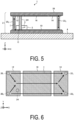
- FIGs. 5, 6 , and 7 are views for describing a flow of a current in the antenna 2 according to the first embodiment.
- FIG. 5 is a view illustrating a flow of a current in the wireless communication apparatus according to the first embodiment.
- FIG. 5 illustrates a cross section at the same position as line I-I in FIG. 2 .
- FIG. 6 is a view illustrating a flow of a current in the upper surface conductor of the antenna according to the first embodiment.
- FIG. 7 is a view illustrating a flow of a current in the lower surface conductor of the antenna according to the first embodiment.
- a current I flows so as to circulate through the first conductor 10, the first connection conductors 20, the second conductor 12, the fourth conductor 16, the third conductor 14, the second connection conductors 22, and the first conductor 10 in this order.
- FIG. 8 is a view for describing flows of magnetic fields inside the antenna 2 according to the first embodiment.
- FIG. 8 schematically illustrates flows of magnetic fields between the first conductor 10 and the second conductor 12, the third conductor 14, and the fourth conductor 16.
- a magnetic field M1 is a magnetic field generated by a current flowing through the first connection conductor 20 1 .
- a magnetic field M2 is a magnetic field generated by a current flowing through the first connection conductor 20 2 . Since the directions of the currents flowing through the first connection conductor 20 1 and the first connection conductor 20 2 are the same, the directions of the magnetic field M1 and the magnetic field M2 are the same.
- the magnetic field M1 and the magnetic field M2 are counterclockwise circular magnetic fields surrounding the first connection conductor 20 1 and the first connection conductor 20 2 , respectively, when viewed from directly above the X-Y plane.
- a magnetic field M3 is a magnetic field generated by a current flowing through the second connection conductor 22 1 .
- a magnetic field M4 is a magnetic field generated by a current flowing through the second connection conductor 22 2 . Since the directions of the currents flowing through the second connection conductor 22 1 and the second connection conductor 22 2 are the same, the directions of the magnetic field M3 and the magnetic field M4 are the same.
- the magnetic field M3 and the magnetic field M4 are clockwise circular magnetic fields surrounding the second connection conductor 22 1 and the second connection conductor 22 2 , respectively, when viewed from directly above the X-Y plane.
- the directions of the currents flowing through the first connection conductors 20 are opposite to the directions of the currents flowing through the second connection conductors 22
- the directions of the magnetic field M1 and the magnetic field M2 are opposite to the directions of the magnetic field M3 and the magnetic field M4.
- a magnetic field M5 is a magnetic field generated by a current flowing through the power feeding conductor 24.
- the magnetic field M5 is a counterclockwise circular magnetic field surrounding the power feeding conductor 24 when viewed from directly above the X-Y plane. Since the direction of the current flowing through the power feeding conductor 24 is the same as the directions of the currents flowing through the first connection conductors 20, the direction of the magnetic field M5 is the same as the directions of the magnetic field M1 and the magnetic field M2.
- a magnetic field M6 is a magnetic field near the center in the X axis direction, which is generated by current flowing through the first conductor 10, the second conductor 12, the third conductor 14, and the fourth conductor 16.
- the magnetic field M6 is a magnetic field parallel to the Y axis direction when viewed from directly above the X-Y plane.
- the magnetic field M6 is a magnetic field flowing from the -Y axis direction to the +Y axis direction.
- the direction of the current flowing through the first conductor 10 is opposite to the direction of the current flowing through the second conductor 12, the third conductor 14, and the fourth conductor 16.
- the direction of the magnetic field generated by the current flowing through the first conductor 10 is opposite to the direction of the magnetic field generated by the current flowing through the second conductor 12, the third conductor 14, and the fourth conductor 16.
- the directions of the magnetic fields between the first conductor 10 and the second conductor 12, the third conductor 14, and the fourth conductor 16 are the same such as the +Y axis direction or the -Y axis direction.
- the magnetic field M6 is the sum of the magnetic field generated by the current flowing through the first conductor 10, the magnetic field generated by the current flowing through the second conductor 12, the third conductor 14, and the fourth conductor 16, and the magnetic fields generated by the currents flowing through the first connection conductors 20 and the second connection conductors 22.
- Each of the directions of the magnetic field M1 to the magnetic field M4 between the first conductor 10 and the second conductor 12, the third conductor 14, and the fourth conductor 16 is the +Y axis direction.
- the connection conductors are spaced apart from each other, the influence of the magnetic field M1 to the magnetic field M4 on the magnetic field M6 is relatively small.
- the directions of the magnetic field M1 and the magnetic field M2 are opposite between the first connection conductor 20 1 and the first connection conductor 20 2 .
- the magnetic field M1 and the magnetic field M2 cancel each other between the first connection conductor 20 1 and the first connection conductor 20 2 , and the magnetic field becomes weak.
- the directions of the magnetic field M3 and the magnetic field M4 are opposite between the second connection conductor 22 1 and the second connection conductor 22 2 .
- the magnetic field M3 and the magnetic field M4 cancel each other between the second connection conductor 22 1 and the second connection conductor 22 2 , and the magnetic field becomes weak.
- FIG. 9 is a view illustrating a simulation result of a magnetic field strength inside the antenna 2 according to the first embodiment.
- the color is darker as a region has a higher magnetic field strength, and the color is lighter as a region has a lower magnetic field strength.
- regions around the first connection conductor 20 1 , the first connection conductor 20 2 , the second connection conductor 22 1 , the second connection conductor 22 2 , and the power feeding conductor 24 are regions having the highest magnetic field strengths.
- a region near the center in the longitudinal direction is a region having a relatively high magnetic field strength.
- a region between the first connection conductor 20 1 and the first connection conductor 20 2 and a region between the second connection conductor 22 1 and the second connection conductor 22 2 are regions having the lowest magnetic field strengths.
- the magnetic fields have different flows and strengths at different locations inside the antenna 2.
- the location where the communication unit 3 is disposed inside the antenna 2 is determined based on the flow of the magnetic field and/or the magnetic field strength.
- the communication unit 3 is disposed at a position where the magnetic field strength is relatively high inside the antenna 2.
- the communication unit 3 is disposed in the vicinity of the first connection conductors 20 or the second connection conductors 22 where the magnetic field strength is relatively high.
- FIG. 10 is a view for describing a method of disposing a communication unit 3 according to a first comparative example.
- FIG. 10 is a view of a first conductor 10 when viewed from the above.
- the communication unit 3 is disposed between a second connection conductor 22 1 and a second connection conductor 22 2 at the first conductor 10.
- the communication unit 3 is disposed between the second connection conductor 22 1 and the second connection conductor 22 2 at the first conductor 10 such that the longitudinal direction of the communication unit 3 and the longitudinal direction of the first conductor 10 are along each other.
- FIG. 11 is a view illustrating flows of magnetic fields inside an antenna 2 according to the first comparative example.
- FIG. 11 is a cross-sectional view taken along line A-A in FIG. 10 .
- the communication unit 3 is disposed between the second connection conductor 22 1 and the second connection conductor 22 2 .
- a magnetic field M3 is generated around the second connection conductor 22 1 .
- a magnetic field M4 is disposed around the second connection conductor 22 2 . Since the communication unit 3 is disposed in a region where the magnetic field is weak, the magnetic field hardly flows in a space between a third conductor 14 and the communication unit 3. That is, when the communication unit 3 is disposed in a region where the magnetic field is weakened because the direction of the magnetic field M3 and the direction of the magnetic field M4 are opposite to each other, the magnetic fields do not weaken each other in the region. Thus, the magnetic field becomes stronger compared to a case in which the communication unit 3 is not disposed.
- FIG. 12 is a graph for describing the radiation efficiency of the antenna according to the first comparative example.
- a graph G1 indicates the total radiation efficiency of the antenna 2 when the communication unit 3 is not disposed.
- a graph G2 indicates the total radiation efficiency of the antenna 2 when the communication unit 3 is disposed between the second connection conductor 22 1 and the second connection conductor 22 2 at the first conductor 10.
- the resonant frequency of the antenna 2 is approximately 900 MHz.
- the resonant frequency of the antenna 2 is 800 MHz or less.
- the inductance component of the antenna 2 increases, which shifts the resonant frequency toward a lower frequency. That is, when the communication unit 3 is disposed between the second connection conductor 22 1 and the second connection conductor 22 2 at the first conductor 10, the radiation characteristic changes from that of the antenna 2 when the communication unit 3 is not disposed at the first conductor 10.
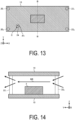
- FIG. 13 is a view for describing a method of disposing a communication unit 3 according to a second comparative example.
- FIG. 13 is a view of a first conductor 10 when viewed from the above.
- the communication unit 3 is disposed at a center portion of the first conductor 10.
- the communication unit 3 is disposed at the center portion of the first conductor 10 such that the longitudinal direction of the communication unit 3 and the longitudinal direction of the first conductor 10 are along each other.
- FIG. 14 is a view illustrating a flow of a magnetic field inside an antenna 2 according to the second comparative example.
- FIG. 14 is a cross-sectional view taken along line B-B in FIG. 13 .
- the communication unit 3 is disposed at the center portion of the first conductor 10.
- a magnetic field M6 is generated at the center portion of the first conductor 10.
- a part of the magnetic field M6 is blocked by the communication unit 3, and the rest thereof flows through a space between a third conductor 14 and the communication unit 3. That is, since the communication unit 3 is disposed at the center portion of the first conductor 10, the magnetic field at the center portion of the first conductor 10 becomes weaker than when the communication unit 3 is not disposed.
- FIG. 15 is a graph for describing the radiation efficiency of the antenna according to the second comparative example.
- a graph G1 indicates the total radiation efficiency of the antenna 2 when the communication unit 3 is not disposed.
- a graph G3 indicates the total radiation efficiency of the antenna 2 when the communication unit 3 is disposed at the center portion of the first conductor 10 such that the longitudinal direction of the communication unit 3 and the longitudinal direction of the first conductor 10 are along each other.
- the resonant frequency of the antenna 2 is approximately 900 MHz.
- the resonant frequency of the antenna 2 when the communication unit 3 is disposed at the center portion of the first conductor 10 is 900 MHz or more.
- the inductance component of the antenna 2 decreases, which shifts the resonant frequency toward a higher frequency. That is, when the communication unit 3 is disposed at the center portion of the first conductor 10, the radiation characteristic changes from that of the antenna 2 when the communication unit 3 is not disposed at the first conductor 10.
- FIG. 16 is a view for describing the method of disposing the communication unit 3 according to the first embodiment.
- FIG. 16 is a view of the first conductor 10 when viewed from the above.
- the communication unit 3 is disposed in the vicinity of the second connection conductor 22 1 at the first conductor 10.
- the communication unit 3 is disposed in the vicinity of the second connection conductor 22 1 at the first conductor 10 such that the longitudinal direction of the communication unit 3 and the longitudinal direction of the first conductor 10 are along each other.
- FIG. 17 is a view illustrating flows of magnetic fields inside the antenna 2 according to the first embodiment.
- FIG. 17 is a cross-sectional view taken along line C-C in FIG. 16 .
- the communication unit 3 is disposed in the vicinity of the second connection conductor 22 1 .
- a magnetic field M3 is generated around the second connection conductor 22 1 . Since the communication unit 3 is disposed in the vicinity of the second connection conductor 22 1 , the strength of the magnetic field M3 is high around the communication unit 3. Thus, the magnetic field M3 flows through a space between the communication unit 3 and the third conductor 14 without being blocked by the communication unit 3. Thus, the magnetic field M3 generated around the second connection conductor 22 1 and a magnetic field M4 generated around the second connection conductor 22 2 cancel each other.
- FIG. 18 is a graph for describing the radiation efficiency of the antenna according to the first embodiment.
- a graph G1 indicates the total radiation efficiency of the antenna 2 when the communication unit 3 is not disposed.
- a graph G4 indicates the total radiation efficiency of the antenna 2 when the communication unit 3 is disposed in the vicinity of the second connection conductor 22 1 at the first conductor 10.
- the resonant frequency of the graph G1 and the resonant frequency of the graph G4 are 900 MHz and substantially the same.
- the total radiation efficiency at the resonant frequency of the graph G1 is approximately -2 dB and is good.
- the total radiation efficiency at the resonant frequency of the graph G4 is slightly lower than -2 dB but is good.
- the graph G4 indicates a characteristic close to that of the graph G1 in the band from 750 MHz to 950 MHz. That is, it can be said that the radiation characteristic of the antenna 2 in which the communication unit 3 is disposed in the vicinity of the second connection conductor 22 1 is substantially the same as the radiation characteristic of the antenna 2 in which the communication unit 3 is not disposed. That is, when the communication unit 3 is disposed in the vicinity of the second connection conductor 22 1 at the first conductor 10, the antenna 2 and the communication unit 3 can be integrated without change in the characteristic of the antenna 2. Accordingly, the wireless communication apparatus 1 can be miniaturized.
- FIG. 19 is a graph for describing the radiation efficiency of the antenna according to the first embodiment.
- a graph G1 indicates the radiation efficiency of the antenna 2 when the communication unit 3 is not disposed at the first conductor 10.
- a graph G4 indicates the radiation efficiency of the antenna 2 when the communication unit 3 is disposed in the vicinity of the second connection conductor 22 1 at the first conductor 10.
- a graph G5 indicates the radiation efficiency of the antenna 2 when the communication unit 3 is disposed in the vicinity of the second connection conductor 22 2 at the first conductor 10.
- a graph G6 indicates the radiation efficiency of the antenna 2 when the communication unit 3 is disposed in the vicinity of the first connection conductor 20 1 at the first conductor 10. In the example shown in FIG. 19 , it is assumed that the communication unit 3 is disposed at the first conductor 10 such that the longitudinal direction of the communication unit 3 and the longitudinal direction of the first conductor 10 are along each other.
- the graph G4 and the graph G5 substantially match each other. That is, the radiation characteristic of the antenna 2 when the communication unit 3 is disposed in the vicinity of the second connection conductor 22 1 at the first conductor 10 and the radiation characteristic of the antenna 2 when the communication unit 3 is disposed in the vicinity of the second connection conductor 22 2 at the first conductor 10 substantially match each other.
- the radiation characteristic at the resonant frequency is approximately -2 dB.
- the radiation characteristic at the resonant frequency in the graph G6 substantially matches that in the graph G1.
- the radiation characteristic of the antenna 2 at the resonant frequency when the communication unit 3 is disposed in the vicinity of the first connection conductor 20 1 at the first conductor 10 substantially matches the radiation characteristic of the antenna 2 at the resonant frequency when the communication unit 3 is not disposed. That is, it is preferable to dispose the communication unit 3 in the vicinity of the first connection conductor 20 1 at the first conductor 10, rather than in the vicinity of the second connection conductor 22 1 and the second connection conductor 22 2 .
- the communication unit 3 is disposed at the first conductor 10 in the vicinity of the first connection conductor 20 1 , the second connection conductor 22 1 , or the second connection conductor 22 2 .
- the antenna 2 and the communication unit 3 can be integrated.
- the communication unit 3 is preferably disposed in the vicinity of any of the first connection conductor 20 1 , the second connection conductor 22 1 , and the second connection conductor 22 2 other than the first connection conductor 20 2 provided in the vicinity of the feeding point P1 and the power feeding conductor 24.
- the communication unit 3 may be disposed in the vicinity of the first connection conductor 20 2 .
- the communication unit 3 and the feeding point P1 are connected via the feeding line 5. From the viewpoint of the routing of the feeding line 5, it is preferable to dispose the communication unit 3 in the vicinity of the first connection conductor 20 1 or the first connection conductor 20 2 rather than in the vicinity of the second connection conductor 22 1 or the second connection conductor 22 2 .
- FIG. 20 is a view for describing the orientation for disposing the communication unit 3 according to the first embodiment.
- the communication unit 3 is disposed in the vicinity of the second connection conductor 22 1 at the first conductor 10 such that the longitudinal direction of the communication unit 3 is along the lateral direction of the first conductor 10.
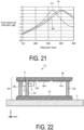
- FIG. 21 is a graph for describing the orientation for disposing the communication unit and the radiation efficiency of the antenna according to the first embodiment.
- a graph G1 indicates the radiation efficiency of the antenna 2 when the communication unit 3 is not disposed at the first conductor 10.
- a graph G4 indicates the total radiation efficiency of the antenna 2 when the communication unit 3 is disposed in the vicinity of the second connection conductor 22 1 at the first conductor 10 such that the longitudinal direction of the communication unit 3 is parallel to the longitudinal direction of the first conductor 10.
- a graph G7 indicates the total radiation efficiency of the antenna 2 when the communication unit 3 is disposed in the vicinity of the second connection conductor 22 1 at the first conductor 10 such that the longitudinal direction of the communication unit 3 is parallel to the lateral direction of the first conductor 10.
- the resonant frequency of the antenna 2 is 900 MHz or less.
- the communication unit 3 can reach a region between the second connection conductor 22 1 and the second connection conductor 22 2 where the magnetic field is weakened.
- the magnetic field is not weakened in the region between the second connection conductor 22 1 and the second connection conductor 22 2 , the magnetic field becomes stronger compared to the case where the communication unit 3 is not disposed. That is, when the communication unit 3 is disposed between the second connection conductor 22 1 and the second connection conductor 22 2 at the first conductor 10, the inductance component of the antenna 2 increases, which shifts the resonant frequency toward a lower frequency.
- the communication unit 3 is preferably disposed in the vicinity of the second connection conductor 22 1 so as not to reach a region between the second connection conductor 22 1 and the second connection conductor 22 2 where the magnetic field is weakened.
- the communication unit 3 is preferably disposed such that the lateral direction of the communication unit 3 is parallel to the lateral direction of the first conductor 10.
- FIG. 22 is a view illustrating the configuration example of the wireless communication apparatus according to the second embodiment.
- FIG. 23 is a view illustrating a configuration example of an upper surface conductor of an antenna according to the second embodiment.
- FIG. 22 is a cross-sectional view taken along line II-II in FIG. 23 . Note that since the configuration of a lower surface conductor of the antenna according to the second embodiment is the same as the configuration of the first conductor 10 illustrated in FIG. 3 , description thereof will be omitted.
- a wireless communication apparatus 1A includes an antenna 2A and a communication unit 3.
- the antenna 2A includes a first conductor 10, a second conductor 12A, a third conductor 14A, a fourth conductor 16A, a first connection conductor 20 1 , a first connection conductor 20 2 , a second connection conductor 22 1 , a second connection conductor 22 2 , a power feeding conductor 24, and a housing 26.
- the communication unit 3 is disposed at the second conductor 12A or the third conductor 14A of the upper surface conductor inside the antenna 2A.
- the wireless communication apparatus 1A of the second embodiment is different from the wireless communication apparatus 1 illustrated in FIG. 1 .
- the communication unit 3 is disposed at the second conductor 12A.
- the communication unit 3 is disposed in the vicinity of the first connection conductor 20 1 at the second conductor 12A such that the longitudinal direction of the communication unit 3 is parallel to the longitudinal direction of the antenna 2A.
- the communication unit 3 may be disposed at the third conductor 14A.
- the second conductor 12A is longer in the X axis direction than the second conductor 12 illustrated in FIG. 2 .
- the second conductor 12A is formed to be long in the X axis direction to such an extent that the communication unit 3 can be disposed in the vicinity of the first conductor 10 such that the longitudinal direction of the communication unit 3 is parallel to the longitudinal direction of the antenna 2A.
- the third conductor 14A is longer in the X axis direction than the third conductor 14 illustrated in FIG. 2 .
- the third conductor 14A is formed to be long in the X axis direction to such an extent that the communication unit 3 can be disposed in the vicinity of the second conductor 12 such that the longitudinal direction of the communication unit 3 is parallel to the longitudinal direction of the antenna 2A.
- the length of the second conductor 12A in the X axis direction is the same as the length of the third conductor 14A in the X axis direction.
- the second conductor 12A and the third conductor 14A are formed longer than the second conductor 12 and the third conductor 14 illustrated in FIG. 2 respectively and, by this lengthened amount, the fourth conductor 16A is formed shorter in the X axis direction than the fourth conductor 16 illustrated in FIG. 2 .
- the length of the fourth conductor 16A in the X axis direction is shorter than the lengths of the second conductor 12A and the third conductor 14A.
- a feeding point P1 is provided at the second conductor 12A.
- a clearance C is provided between the feeding point P1 and the second conductor 12A.
- One end of the power feeding conductor 24 is connected to the feeding point P 1, and the other end thereof is connected to the first conductor 10. Since the clearance C is provided between the feeding point P1 and the second conductor 12A, the power feeding conductor 24 and the second conductor 12A are not connected to each other.
- the feeding point P1 may be provided at any of the third conductor 14A and the fourth conductor 16A with a gap therebetween.
- one end of the power feeding conductor 24 can be connected to the feeding point P1 provided at any of the second conductor 12A, the third conductor 14A, and the fourth conductor 16A with a gap therebetween, and the other end thereof can be connected to the first conductor 10 facing the feeding point P1.
- FIG. 24 is a graph for describing the radiation efficiency of the antenna according to the second embodiment.
- a graph G10 indicates the total radiation efficiency of the antenna 2A when the communication unit 3 is not disposed.
- a graph G1 1 indicates the radiation efficiency of the antenna 2A when the communication unit 3 is disposed in the vicinity of the first connection conductor 20 1 at the first conductor 10 such that the longitudinal direction of the communication unit 3 is parallel to the longitudinal direction of the antenna 2A, as illustrated in FIG. 25 .
- FIG. 25 it is assumed that the feeding point P1 is provided at the first conductor 10 via a clearance C.
- FIG. 25 it is assumed that the feeding point P1 is provided at the first conductor 10 via a clearance C.
- a graph G12 indicates the radiation efficiency of the antenna 2A when the communication unit 3 is disposed in the vicinity of the first connection conductor 20 1 at the second conductor 12A such that the longitudinal direction of the communication unit 3 is parallel to the longitudinal direction of the antenna 2A.
- the resonant frequency of the antenna 2A when the communication unit 3 is not disposed is approximately 850 MHz.
- the total radiation efficiency at the resonant frequency of the graph G10 is approximately -3 dB and is good.
- the resonant frequency of the antenna 2A is approximately 850 MHz.
- the total radiation efficiency at the resonant frequency of the graph G11 is approximately -3 dB and is good.
- the resonant frequency of the antenna 2A is approximately 850 MHz.
- the total radiation efficiency at the resonant frequency of the graph G12 is approximately -3 dB and is good.
- the resonant frequencies of the graph G11 and the graph G12 and the radiation characteristics at the resonant frequencies substantially match the resonant frequency of the graph G10 and the radiation characteristic at the resonant frequency.
- the resonant frequencies of the graph G11 and the graph G12 substantially match the resonant frequency of the graph G10.
- the radiation characteristics of the graph G11 and the graph G12 substantially match in the range from 700 MHz to 950 MHz. That is, the radiation characteristics in the range from 700 MHz to 950 MHz are substantially matched between the case where the communication unit 3 is disposed at the first conductor 10 and the case where the communication unit 3 is disposed at the second conductor 12A. That is, for this reason, the communication unit 3 can be disposed at any of the first conductor 10, the second conductor 12A, and the third conductor 14A in the second embodiment.
- the communication unit 3 may be disposed at the second conductor 12A or may be disposed at the third conductor 14A. From the viewpoint of the routing of a feeding line 5, the communication unit 3 is preferably disposed at one of the second conductor 12A and the third conductor 14A that is closer to the feeding point P1. In the example illustrated in FIGs. 22 and 23 , the communication unit 3 is preferably disposed at the second conductor 12A.
- the second embodiment has been described on the assumption that the communication unit 3 is mounted at the second conductor 12A or the third conductor 14A.
- the lower surface conductor may be made of one sheet metal or the like.
- FIG. 26 is a view illustrating the configuration example of the lower surface conductor according to the variation of the second embodiment.
- a lower surface conductor 40 includes a first conductor 10A, a first connection conductor 20A 1 , a first connection conductor 20A 2 , a second connection conductor 22A 1 , a second connection conductor 22A 2 , and a power feeding conductor 24A.
- the lower surface conductor 40 is a sheet metal in which the first conductor 10A, the first connection conductor 20A 1 , the first connection conductor 20A 2 , the second connection conductor 22A 1 , the second connection conductor 22A 2 , and the power feeding conductor 24 are integrally formed.
- the first connection conductor 20A 1 and the first connection conductor 20A 2 are bent toward the X axis direction so as to be parallel to the Z axis direction, and thus the first conductor 10A and a second conductor (not illustrated) are connected.
- the second connection conductor 22A 1 , the second connection conductor 22A 2 , and the power feeding conductor 24A are bent toward the -X axis direction so as to be parallel to the Z axis direction, and thus the first conductor 10A and a fourth conductor (not illustrated) are connected.
- the first conductor 10A, the first connection conductor 20A 1 , the first connection conductor 20A 2 , the second connection conductor 22A 1 , the second connection conductor 22A 2 , and the power feeding conductor 24A are integrated as illustrated in FIG. 26 , and thus the antenna 2A illustrated in FIG. 22 can be easily manufactured. The manufacturing cost of the antenna 2A can be suppressed.
- the antenna 2 according to the first embodiment and the antenna 2A according to the second embodiment may be mounted at various structures.
- the structures include a container and a pallet used for transportation of various articles.
- the antenna 2 or the antenna 2A transmits and receives various types of information related to the articles accommodated in the container to and from a server apparatus or the like.
- the structures may include a delivery box accommodating a delivery item.
Landscapes
- Engineering & Computer Science (AREA)
- Computer Networks & Wireless Communication (AREA)
- Support Of Aerials (AREA)
Applications Claiming Priority (2)
| Application Number | Priority Date | Filing Date | Title |
|---|---|---|---|
| JP2021211726 | 2021-12-24 | ||
| PCT/JP2022/047492 WO2023120678A1 (ja) | 2021-12-24 | 2022-12-22 | 無線通信装置、および構造体 |
Publications (1)
| Publication Number | Publication Date |
|---|---|
| EP4456332A1 true EP4456332A1 (en) | 2024-10-30 |
Family
ID=86902769
Family Applications (1)
| Application Number | Title | Priority Date | Filing Date |
|---|---|---|---|
| EP22911380.8A Withdrawn EP4456332A1 (en) | 2021-12-24 | 2022-12-22 | Wireless communication device and structure |
Country Status (4)
| Country | Link |
|---|---|
| US (1) | US20250062540A1 (https=) |
| EP (1) | EP4456332A1 (https=) |
| JP (1) | JP7612896B2 (https=) |
| WO (1) | WO2023120678A1 (https=) |
Families Citing this family (1)
| Publication number | Priority date | Publication date | Assignee | Title |
|---|---|---|---|---|
| WO2025070393A1 (ja) * | 2023-09-28 | 2025-04-03 | 京セラ株式会社 | アンテナおよび無線通信装置 |
Family Cites Families (5)
| Publication number | Priority date | Publication date | Assignee | Title |
|---|---|---|---|---|
| JP3369810B2 (ja) * | 1995-09-12 | 2003-01-20 | 株式会社東芝 | 通信モジュール |
| JP2019140658A (ja) | 2017-03-21 | 2019-08-22 | 京セラ株式会社 | 複合アンテナ、無線通信モジュール、および無線通信機器 |
| US11888231B2 (en) | 2019-06-25 | 2024-01-30 | Kyocera Corporation | Antenna, wireless communication module, and wireless communication device |
| JP6926174B2 (ja) | 2019-11-26 | 2021-08-25 | 京セラ株式会社 | アンテナ、無線通信モジュール及び無線通信機器 |
| JP7361601B2 (ja) | 2019-12-26 | 2023-10-16 | 京セラ株式会社 | アンテナユニット、無線通信モジュール及び無線通信機器 |
-
2022
- 2022-12-22 US US18/723,077 patent/US20250062540A1/en active Pending
- 2022-12-22 WO PCT/JP2022/047492 patent/WO2023120678A1/ja not_active Ceased
- 2022-12-22 JP JP2023569556A patent/JP7612896B2/ja active Active
- 2022-12-22 EP EP22911380.8A patent/EP4456332A1/en not_active Withdrawn
Also Published As
| Publication number | Publication date |
|---|---|
| JP7612896B2 (ja) | 2025-01-14 |
| JPWO2023120678A1 (https=) | 2023-06-29 |
| WO2023120678A1 (ja) | 2023-06-29 |
| US20250062540A1 (en) | 2025-02-20 |
Similar Documents
| Publication | Publication Date | Title |
|---|---|---|
| US11831076B2 (en) | Antenna, wireless communication module, and wireless communication device | |
| US11916294B2 (en) | Antenna, wireless communication module, and wireless communication device | |
| US11870144B2 (en) | Antenna, wireless communication module, and wireless communication device | |
| US12126097B2 (en) | Antenna, wireless communication module, and wireless communication device | |
| JP6288318B2 (ja) | 無線通信デバイスおよびそれを備えた物品 | |
| EP4456332A1 (en) | Wireless communication device and structure | |
| US11843174B2 (en) | Antenna element, array antenna, communication unit, mobile body, and base station | |
| US11152691B2 (en) | Dual broadband antenna system for vehicles | |
| US11955736B2 (en) | Antenna, wireless communication module, and wireless communication device | |
| US12074385B2 (en) | Antenna, wireless communication module, and wireless communication device | |
| US11784402B2 (en) | Antenna, wireless communication module, and wireless communication device | |
| JP7618022B2 (ja) | アンテナ及び無線通信装置 | |
| US11888231B2 (en) | Antenna, wireless communication module, and wireless communication device | |
| US20230411848A1 (en) | Antenna, wireless communication module, and wireless communication device | |
| WO2013136741A1 (ja) | アンテナ装置 | |
| US12160055B2 (en) | Antenna, wireless communication module, and wireless communication device | |
| WO2022209053A1 (ja) | マルチアンテナ、無線通信デバイス、およびトラッキングシステム | |
| WO2025018273A1 (ja) | アンテナ、無線通信装置および構造体 | |
| WO2025070393A1 (ja) | アンテナおよび無線通信装置 | |
| US20170141457A1 (en) | Antenna device and wireless device |
Legal Events
| Date | Code | Title | Description |
|---|---|---|---|
| STAA | Information on the status of an ep patent application or granted ep patent |
Free format text: STATUS: THE INTERNATIONAL PUBLICATION HAS BEEN MADE |
|
| PUAI | Public reference made under article 153(3) epc to a published international application that has entered the european phase |
Free format text: ORIGINAL CODE: 0009012 |
|
| STAA | Information on the status of an ep patent application or granted ep patent |
Free format text: STATUS: REQUEST FOR EXAMINATION WAS MADE |
|
| 17P | Request for examination filed |
Effective date: 20240619 |
|
| AK | Designated contracting states |
Kind code of ref document: A1 Designated state(s): AL AT BE BG CH CY CZ DE DK EE ES FI FR GB GR HR HU IE IS IT LI LT LU LV MC ME MK MT NL NO PL PT RO RS SE SI SK SM TR |
|
| DAV | Request for validation of the european patent (deleted) | ||
| DAX | Request for extension of the european patent (deleted) | ||
| STAA | Information on the status of an ep patent application or granted ep patent |
Free format text: STATUS: THE APPLICATION HAS BEEN WITHDRAWN |
|
| 18W | Application withdrawn |
Effective date: 20250912 |