EP4456330A1 - Mehrband-basisstationsantenne mit verbesserter strahlbreite - Google Patents
Mehrband-basisstationsantenne mit verbesserter strahlbreite Download PDFInfo
- Publication number
- EP4456330A1 EP4456330A1 EP22912063.9A EP22912063A EP4456330A1 EP 4456330 A1 EP4456330 A1 EP 4456330A1 EP 22912063 A EP22912063 A EP 22912063A EP 4456330 A1 EP4456330 A1 EP 4456330A1
- Authority
- EP
- European Patent Office
- Prior art keywords
- column
- band
- radiators
- base station
- low
- Prior art date
- Legal status (The legal status is an assumption and is not a legal conclusion. Google has not performed a legal analysis and makes no representation as to the accuracy of the status listed.)
- Pending
Links
Images





Classifications
-
- H—ELECTRICITY
- H01—ELECTRIC ELEMENTS
- H01Q—ANTENNAS, i.e. RADIO AERIALS
- H01Q21/00—Antenna arrays or systems
- H01Q21/24—Combinations of antenna units polarised in different directions for transmitting or receiving circularly and elliptically polarised waves or waves linearly polarised in any direction
-
- H—ELECTRICITY
- H01—ELECTRIC ELEMENTS
- H01Q—ANTENNAS, i.e. RADIO AERIALS
- H01Q1/00—Details of, or arrangements associated with, antennas
- H01Q1/12—Supports; Mounting means
- H01Q1/22—Supports; Mounting means by structural association with other equipment or articles
- H01Q1/24—Supports; Mounting means by structural association with other equipment or articles with receiving set
- H01Q1/241—Supports; Mounting means by structural association with other equipment or articles with receiving set used in mobile communications, e.g. GSM
- H01Q1/246—Supports; Mounting means by structural association with other equipment or articles with receiving set used in mobile communications, e.g. GSM specially adapted for base stations
-
- H—ELECTRICITY
- H01—ELECTRIC ELEMENTS
- H01Q—ANTENNAS, i.e. RADIO AERIALS
- H01Q1/00—Details of, or arrangements associated with, antennas
- H01Q1/36—Structural form of radiating elements, e.g. cone, spiral, umbrella; Particular materials used therewith
- H01Q1/38—Structural form of radiating elements, e.g. cone, spiral, umbrella; Particular materials used therewith formed by a conductive layer on an insulating support
-
- H—ELECTRICITY
- H01—ELECTRIC ELEMENTS
- H01Q—ANTENNAS, i.e. RADIO AERIALS
- H01Q1/00—Details of, or arrangements associated with, antennas
- H01Q1/52—Means for reducing coupling between antennas; Means for reducing coupling between an antenna and another structure
- H01Q1/521—Means for reducing coupling between antennas; Means for reducing coupling between an antenna and another structure reducing the coupling between adjacent antennas
- H01Q1/523—Means for reducing coupling between antennas; Means for reducing coupling between an antenna and another structure reducing the coupling between adjacent antennas between antennas of an array
-
- H—ELECTRICITY
- H01—ELECTRIC ELEMENTS
- H01Q—ANTENNAS, i.e. RADIO AERIALS
- H01Q15/00—Devices for reflection, refraction, diffraction or polarisation of waves radiated from an antenna, e.g. quasi-optical devices
- H01Q15/14—Reflecting surfaces; Equivalent structures
-
- H—ELECTRICITY
- H01—ELECTRIC ELEMENTS
- H01Q—ANTENNAS, i.e. RADIO AERIALS
- H01Q21/00—Antenna arrays or systems
- H01Q21/24—Combinations of antenna units polarised in different directions for transmitting or receiving circularly and elliptically polarised waves or waves linearly polarised in any direction
- H01Q21/26—Turnstile or like antennas comprising arrangements of three or more elongated elements disposed radially and symmetrically in a horizontal plane about a common centre
-
- H—ELECTRICITY
- H01—ELECTRIC ELEMENTS
- H01Q—ANTENNAS, i.e. RADIO AERIALS
- H01Q21/00—Antenna arrays or systems
- H01Q21/28—Combinations of substantially independent non-interacting antenna units or systems
-
- H—ELECTRICITY
- H01—ELECTRIC ELEMENTS
- H01Q—ANTENNAS, i.e. RADIO AERIALS
- H01Q5/00—Arrangements for simultaneous operation of antennas on two or more different wavebands, e.g. dual-band or multi-band arrangements
- H01Q5/40—Imbricated or interleaved structures; Combined or electromagnetically coupled arrangements, e.g. comprising two or more non-connected fed radiating elements
- H01Q5/42—Imbricated or interleaved structures; Combined or electromagnetically coupled arrangements, e.g. comprising two or more non-connected fed radiating elements using two or more imbricated arrays
Definitions
- the present disclosure relates to a multi-band base station antenna, and more particularly, to a multi-band base station antenna having an improved beamwidth.
- the frequency band required for base station antennas is gradually increasing.
- miniaturization of the antenna is also required.
- radiators of various bands are arranged, and the arrangement spacing between each radiator is inevitably narrowed to meet the miniaturization requirement.
- radiators arranged at narrow intervals inevitably had deteriorated isolation characteristics, and that the beam width also widened due to adjacent radiators.
- the deterioration of the isolation characteristics and the beam width results in deterioration of the quality of communication services.
- An object of the present disclosure is to propose a multi-band base station antenna that can prevent distortion of the beam width of each radiator due to interference between radiators.
- Another object of the present disclosure is to propose a multi-band base station antenna that can secure good isolation characteristics between radiators.
- a multi-band base station antenna comprising: a reflective plate; a plurality of first low-band radiators arranged on the reflective plate along a first column; a plurality of second low-band radiators arranged on the reflective plate along a second column, which is parallel to the first column and is spaced apart from the first column; a plurality of high-band radiators arranged on the reflective plate; and a plurality of vertical choke members arranged, between the first column and the second column, in the direction parallel to that of the first column and the second column, wherein the vertical choke members comprise a first substrate, a meander line is formed on the first substrate, and a metal line is formed under the first substrate.
- the multi-band base station antenna may further include a plurality of horizontal choke members arranged in the direction perpendicular to that of the vertical choke member.
- the horizontal choke members may comprise a second substrate, and a meander line may be formed on the second substrate.
- the vertical choke member and the horizontal choke member may be arranged at a position equal to or higher than that of the low-band radiators.
- the vertical choke member and the horizontal choke member may be arranged for each pair of the first low-band radiator and the second low-band radiator.
- the longitudinal end of the vertical choke member may be arranged in contact with or adj acent to the central portion of the horizontal choke member, forming a'T' shape.
- a multi-band base station antenna comprising: a reflective plate; a plurality of first radiators arranged on the reflective plate along a first column; a plurality of second radiators arranged on the reflective plate along a second column, which is parallel to the first column and is spaced apart from the first column; a plurality of vertical choke members arranged, between the first column and the second column, in a direction parallel to that of the first column and the second column; and a plurality of horizontal choke members arranged in a direction perpendicular to the plurality of vertical choke members.
- the multi-band base station antenna of the present disclosure has the advantage of preventing distortion of the beam width of each radiator due to interference between radiators.
- the multi-band base station antenna of the present disclosure has the advantage of securing good isolation characteristics between radiators.
- FIG. 1 is a diagram showing the structure of a multi-band base station antenna according to an embodiment of the present disclosure
- FIG. 2 is a diagram showing a first partial cross-section of a multi-band base station antenna according to an embodiment of the present disclosure
- FIG. 3 is a diagram showing a second partial cross-section of a multi-band base station antenna according to an embodiment of the present disclosure.
- the multi-band base station antenna comprises a plurality of first low-band radiators 100, a plurality of second low-band radiators 200, a plurality of high-band radiators 300, and a reflective plate 400.
- FIG. 1 is a diagram showing a portion of a multi-band base station antenna for convenience of explanation, and the structure shown in FIG. 1 may be repeatedly extended.
- the plurality of first low-band radiators 100 are arranged along the first column 110, and the plurality of second low-band radiators 200 are arranged along the second column 210.
- FIG. 1 shows a case where two first radiators 100 are arranged along the first column 110 and two second radiators 200 are arranged along the second column 210. However, since the diagram of FIG. 1 shows a portion of the antenna, a greater number of first low-band radiators 100 and second low-band radiators 200 may be arranged.
- FIG. 1 shows a case where the low-band radiators 100 and 200 form two columns, but it will be obvious to those skilled in the art that the number of columns of low-band radiators may be changed.
- the first low-band radiators 100 and the second low-band radiators 200 are arranged on the reflective plate 400.
- the first low-band radiators 100 and the second low-band radiators 200 may have the same shape and size, and emit signals in the same band.
- the first low-band radiators 100 and the second low-band radiators 200 may be radiators that emit dual polarization of +45 degree polarization and -45 degree polarization.
- the first column 110 and the second column 210 are parallel, and the first low-band radiators 100 and second low-band radiators 200 are spaced apart at a preset interval.
- the first low-band radiators 100 and the second low-band radiators cannot be sufficiently spaced apart.
- the beam emitted from the first low-band radiators 100 and the beam emitted from the second low-band radiators 200 overlap, and this overlap causes the beam width of each low-band radiator to unintentionally widen.
- the beam width when the first low-band radiators 100 and the second low-band radiators 200 emit beams without being influenced by each other is 70 degrees.
- the beams of the first low-band radiators 100 and the second low-band radiators 200 overlap, so that the beam width of the first low-band radiators 100 and the second low-band radiators 200 can increase to 90 degrees or more.
- the plurality of high-band radiators 300 are arranged together on the reflective plate 400. Since the size of the radiator is inversely proportional to the frequency at which it emits, the plurality of high-band radiators 300 have a smaller size than the first low-band radiators 100 and the second low-band radiators 200.
- the high-band radiator 300 may also be an radiator that emits dual polarization of +45 degree polarization and -45 degree polarization.
- the multi-band base station antenna of the present disclosure includes a vertical choke member 500 and a horizontal choke member 600.
- the vertical choke members 500 are arranged in a direction parallel to the first column 110 and the second column 210, and the horizontal choke members 600 are arranged in a direction perpendicular to the first column 110 and the second column 210.
- the vertical choke members 500 are preferably disposed at the center of the first column 110 and the second column 210.
- the vertical choke members 500 and the horizontal choke members 600 are disposed at a higher position compared to the high-bandwidth radiators 300.
- FIG. 2 is a partial cross-sectional view of the antenna of the present disclosure viewed from a direction parallel to the column of low-band antennas
- FIG. 3 is a partial cross-sectional view of the antenna of the present disclosure viewed from a direction perpendicular to the column of low-band antennas.
- the vertical choke members 500 and the horizontal choke members 600 are located at a higher position than the low-band radiators 300.
- the height of the vertical choke members 500 and horizontal choke members 600 is preferably the same as that of the low-band radiators 200, but may be located slightly higher as shown in FIGS. 2 and 3 . Meanwhile, it is preferable that the height of the vertical choke members 500 and the height of the horizontal choke members 600 are the same.
- a supporter (not shown) supporting the vertical choke members 500 and the horizontal choke members 600 may be disposed on the antenna so that the vertical choke members 500 and the horizontal choke members 600 are located at a higher position than the low-band radiators 200.
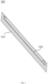
- FIG. 4 is a diagram showing the upper surface of a vertical choke member according to an embodiment of the present disclosure
- FIG. 5 is a diagram showing the lower surface of a vertical choke member according to an embodiment of the present disclosure
- FIG. 6 is a diagram showing a meander line and a metal line of a vertical choke member according to an embodiment of the present disclosure.
- the body of the vertical choke member is a substrate 510, and a meander line 520 is formed on the upper part of the substrate 510.
- the meander line 520 is a zigzag-shaped line and the meander line 520 is made of metal.
- a metal line 530 is formed on the lower part of the substrate 510 of the vertical choke member 500.
- the metal line is an overall horizontal line and extends in the same direction as the longitudinal direction of the substrate 510.
- the terminal portion of the metal line 530 may be bent.
- FIG. 5 shows the terminal portion of the metal line 530 being bent twice.
- the terminal portion of the metal line 530 may be bent to secure the electrical length of the metal line 530.
- the metal line 530 and the meander line 520 are shown on the same plane, and the length of the metal line 530 is set to be longer than that of the meander line 520.
- Atypical choke member of a base station antenna takes the form of a metal plate.
- This type of choke member in the form of a metal plate can contribute to improving the isolation between radiators, but there is a problem of generating a new resonance in the choke member of the metal plate.
- a choke member in the form of a metal plate was not appropriate to prevent the beam width of the first low-band radiators 100 and the second low-band radiators 200 from widening.
- the present disclosure proposes a choke member using the substrate 510 as a body to prevent beam overlap of the first low-band radiators 100 and the second low-band radiators 200, and vertical choke members 500 are used in which a meander line 520 is formed on the upper part of the substrate 510 and a horizontal metal line 530 is formed on the lower part of the substrate 510.
- FIG. 7 is a diagram showing the upper surface of a horizontal choke member according to an embodiment of the present disclosure.
- the horizontal choke member 600 also uses a substrate 610 as a body, and a meander line 620 is formed on the upper part of the substrate. Unlike the vertical choke member 500, no separate metal line is formed on the lower part of the substrate 610 of the horizontal choke member 600.
- FIG. 8 is a diagram showing the arrangement structure of a vertical choke member and a horizontal choke member according to an embodiment of the present disclosure.
- a longitudinal end of the vertical choke member 500 is in contact with the central portion of the horizontal choke member 600, so that the vertical choke member 500 and the horizontal choke member 600 may be arranged to form a 'T' shape.
- the longitudinal end of the vertical choke member 500 may be spaced apart from the horizontal choke member 600 without contacting it.
- the vertical choke member 500 and the horizontal choke member 600 as shown in FIG. 8 may be formed for each pair of the first low-band radiator 100 and the second low-band radiator 200.
- FIG. 1 two pairs of first and second low-band radiators are shown, and thus two vertical choke members 500 and two horizontal choke members 600 are shown.
- first low-band radiators are arranged in the first column and 10 second low-band radiators are arranged in the second column, 10 vertical choke members and 10 horizontal choke members may be arranged.
- the choke member structure of the present disclosure can contribute to improving the isolation between the first low-band radiators 100 and the second low-band radiators 200.
- FIGS. 1 to 8 show a case where the substrates 510 and 610 of the vertical choke members 500 and vertical choke member 600 are arranged perpendicular to the reflective plate 400. However, depending on required characteristics, the substrates 510 and 610 may be arranged parallel to the reflective plate 400.
- FIG. 9 is a diagram for explaining the length constraints of a meander line and a metal line in an antenna according to an embodiment of the present disclosure.
- L the total length of the meander line
- ⁇ c means the center wavelength in the low-band radiator operating frequency band.
- the length of the horizontal line (L 1 ) among the meander lines is preferably set to 0.01379 ⁇ c
- the length of the vertical line (L 2 ) is preferably set to 0.02758 ⁇ c .
- the total summed length of the meander line can be set to 0.74 ⁇ c .
- the total length of the metal line, L10+L11*2+L12*2, may be set to 0.56 ⁇ c .
- FIG. 10 is a graph showing the beam width of low-band radiators when a horizontal choke member and a vertical choke member are not arranged in a multi-band base station antenna.
- the x-axis is frequency and the y-axis is beamwidth.
- the beam width increases as the frequency of the low-band radiator increases.
- the beam width is 75 to 85 degrees in the low band, but the beam width is more than 95 degrees in the high band.
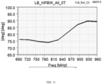
- FIG. 11 is a graph showing the beam width of low-band radiators when a vertical choke member with a meander line and a horizontal choke member with a meander line are arranged in a multi-band base station antenna.
- the graph in FIG. 11 is a graph in which only the meander line is applied to the vertical choke member and the metal line is not applied.
- the overall beam width is narrowed compared to the case where the vertical choke member and the horizontal choke member are not arranged.
- FIG. 12 is a graph showing the beam width of low-band radiators in a multi-band base station antenna to which both vertical and horizontal choke members are applied according to an embodiment of the present disclosure.
- the beam width in the low frequency band is maintained at 70 to 75 degrees.
- the beam width is maintained below 85 degrees even in the high frequency band.
Landscapes
- Physics & Mathematics (AREA)
- Electromagnetism (AREA)
- Engineering & Computer Science (AREA)
- Computer Networks & Wireless Communication (AREA)
- Aerials With Secondary Devices (AREA)
Applications Claiming Priority (2)
| Application Number | Priority Date | Filing Date | Title |
|---|---|---|---|
| KR1020210185743A KR102560247B1 (ko) | 2021-12-23 | 2021-12-23 | 개선된 빔폭을 가지는 다중 대역 기지국 안테나 |
| PCT/KR2022/095147 WO2023121430A1 (ko) | 2021-12-23 | 2022-10-19 | 개선된 빔폭을 가지는 다중 대역 기지국 안테나 |
Publications (2)
| Publication Number | Publication Date |
|---|---|
| EP4456330A1 true EP4456330A1 (de) | 2024-10-30 |
| EP4456330A4 EP4456330A4 (de) | 2025-10-01 |
Family
ID=86903239
Family Applications (1)
| Application Number | Title | Priority Date | Filing Date |
|---|---|---|---|
| EP22912063.9A Pending EP4456330A4 (de) | 2021-12-23 | 2022-10-19 | Mehrband-basisstationsantenne mit verbesserter strahlbreite |
Country Status (4)
| Country | Link |
|---|---|
| US (1) | US12614857B2 (de) |
| EP (1) | EP4456330A4 (de) |
| KR (1) | KR102560247B1 (de) |
| WO (1) | WO2023121430A1 (de) |
Families Citing this family (1)
| Publication number | Priority date | Publication date | Assignee | Title |
|---|---|---|---|---|
| KR102853563B1 (ko) * | 2025-06-01 | 2025-09-02 | 주식회사 케이앤에스아이앤씨 | 올인원 허브지그를 이용한 반사판의 제조방법 및 그 반사판. |
Family Cites Families (13)
| Publication number | Priority date | Publication date | Assignee | Title |
|---|---|---|---|---|
| KR100983613B1 (ko) * | 2008-08-11 | 2010-09-24 | 주식회사 에이스테크놀로지 | 디커플링 소자를 가지는 안테나 |
| KR101094510B1 (ko) * | 2009-10-16 | 2011-12-19 | 주식회사 에이스테크놀로지 | 복사 소자를 둘러싼 초크 부재가 반사판으로부터 이격되어 배열되는 안테나 |
| KR101656577B1 (ko) * | 2014-10-30 | 2016-09-09 | 세종대학교산학협력단 | 주파수 선택 공진기를 포함하는 안테나 |
| CN205509015U (zh) * | 2016-04-13 | 2016-08-24 | 罗森伯格(上海)通信技术有限公司 | 去列间耦合天线阵列 |
| CN110622356B (zh) * | 2017-05-16 | 2021-08-03 | 华为技术有限公司 | 一种天线 |
| KR102405013B1 (ko) * | 2017-09-06 | 2022-06-07 | 삼성전자주식회사 | 안테나 엘리먼트간 격리 구조를 갖는 안테나 장치 |
| KR102412521B1 (ko) * | 2018-01-12 | 2022-06-23 | 주식회사 케이엠더블유 | 안테나 장치 |
| CN109494460B (zh) * | 2018-10-31 | 2020-11-06 | 重庆大学 | 一种具有高隔离度的双极化/圆极化宽带高密度天线阵列 |
| CN113782949A (zh) * | 2020-06-10 | 2021-12-10 | 康普技术有限责任公司 | 具有频率选择表面的基站天线 |
| CN112886278B (zh) * | 2020-11-02 | 2024-09-17 | 武汉汉烯科技有限公司 | 隔离度高的mimo天线阵列 |
| CN114696092A (zh) * | 2020-12-31 | 2022-07-01 | 康普技术有限责任公司 | 带有电介质隔离器的天线组件和基站天线 |
| CN113270719B (zh) * | 2021-04-01 | 2023-04-11 | 中信科移动通信技术股份有限公司 | 天线隔离装置、阵列天线及基站天线 |
| US12489199B2 (en) * | 2022-12-21 | 2025-12-02 | Outdoor Wireless Networks LLC | Base station antennas having partially reflective surface isolation walls |
-
2021
- 2021-12-23 KR KR1020210185743A patent/KR102560247B1/ko active Active
-
2022
- 2022-10-19 EP EP22912063.9A patent/EP4456330A4/de active Pending
- 2022-10-19 WO PCT/KR2022/095147 patent/WO2023121430A1/ko not_active Ceased
-
2024
- 2024-06-20 US US18/748,729 patent/US12614857B2/en active Active
Also Published As
| Publication number | Publication date |
|---|---|
| US20240339761A1 (en) | 2024-10-10 |
| US12614857B2 (en) | 2026-04-28 |
| WO2023121430A1 (ko) | 2023-06-29 |
| EP4456330A4 (de) | 2025-10-01 |
| KR20230096347A (ko) | 2023-06-30 |
| KR102560247B1 (ko) | 2023-07-28 |
Similar Documents
| Publication | Publication Date | Title |
|---|---|---|
| CA2237675C (en) | Reflector-provided dipole antenna | |
| US8659482B2 (en) | MIMO antenna having plurality of isolation adjustment portions | |
| US20020140618A1 (en) | Multiband telecommunication antenna | |
| EP3201986B1 (de) | Antennenvorrichtung für antennensystem einer basisstation | |
| US6525696B2 (en) | Dual band antenna using a single column of elliptical vivaldi notches | |
| US12463329B2 (en) | Multi-band antenna array face and radiator configuration for mitigating interference | |
| EP3968454A1 (de) | Antennenstrahler für basisstation mit funktion zur unterdrückung von unerwünschten resonanzen | |
| US9819095B2 (en) | Wideband wide beamwidth MIMO antenna system | |
| US8009102B2 (en) | Multi-band antenna and multi-band antenna system with enhanced isolation characteristic | |
| KR20130103559A (ko) | 이중 편파 방사 다이폴 안테나 | |
| KR102405013B1 (ko) | 안테나 엘리먼트간 격리 구조를 갖는 안테나 장치 | |
| US11984673B2 (en) | Omni-directional MIMO antenna | |
| US10658754B2 (en) | Antenna array including suppressor | |
| US11831085B2 (en) | Compact antenna radiating element | |
| EP2667448A1 (de) | Kommunikationsvorrichtung und Antennensystem darin | |
| US12614857B2 (en) | Multiband base station antenna having improved beamwidth | |
| CN118336376B (zh) | 透波低频天线及天线组件 | |
| NL2022823B1 (en) | Dual-band directional antenna, wireless device, and wireless communication system | |
| US6426730B1 (en) | Multi-frequency array antenna | |
| US12155121B2 (en) | Ultra wideband isolation for coupling reduction in an antenna array | |
| JP6570482B2 (ja) | 基板型アンテナ | |
| JP3784807B2 (ja) | マイクロストリップアンテナ | |
| US11843161B2 (en) | Radiating element and base station antenna | |
| KR102365968B1 (ko) | 광대역 안테나 방사체 및 협대역 안테나 방사체를 포함하는 안테나 장치 | |
| EP4631136A1 (de) | Ultrabreitband-fransera-antennenstrahler (ufar) für gruppenantennen der fünften und sechser generation (5g/6g) |
Legal Events
| Date | Code | Title | Description |
|---|---|---|---|
| STAA | Information on the status of an ep patent application or granted ep patent |
Free format text: STATUS: THE INTERNATIONAL PUBLICATION HAS BEEN MADE |
|
| PUAI | Public reference made under article 153(3) epc to a published international application that has entered the european phase |
Free format text: ORIGINAL CODE: 0009012 |
|
| STAA | Information on the status of an ep patent application or granted ep patent |
Free format text: STATUS: REQUEST FOR EXAMINATION WAS MADE |
|
| 17P | Request for examination filed |
Effective date: 20240719 |
|
| AK | Designated contracting states |
Kind code of ref document: A1 Designated state(s): AL AT BE BG CH CY CZ DE DK EE ES FI FR GB GR HR HU IE IS IT LI LT LU LV MC ME MK MT NL NO PL PT RO RS SE SI SK SM TR |
|
| DAV | Request for validation of the european patent (deleted) | ||
| DAX | Request for extension of the european patent (deleted) | ||
| REG | Reference to a national code |
Ref country code: DE Ref legal event code: R079 Free format text: PREVIOUS MAIN CLASS: H01Q0021240000 Ipc: H01Q0021280000 |
|
| A4 | Supplementary search report drawn up and despatched |
Effective date: 20250901 |
|
| RIC1 | Information provided on ipc code assigned before grant |
Ipc: H01Q 21/28 20060101AFI20250826BHEP Ipc: H01Q 21/26 20060101ALI20250826BHEP Ipc: H01Q 1/52 20060101ALI20250826BHEP Ipc: H01Q 1/24 20060101ALI20250826BHEP Ipc: H01Q 5/42 20150101ALI20250826BHEP |