EP4456311A1 - Vorrichtung zur maskierung der ausrichtung von elektrodenleitungen - Google Patents
Vorrichtung zur maskierung der ausrichtung von elektrodenleitungen Download PDFInfo
- Publication number
- EP4456311A1 EP4456311A1 EP23760343.6A EP23760343A EP4456311A1 EP 4456311 A1 EP4456311 A1 EP 4456311A1 EP 23760343 A EP23760343 A EP 23760343A EP 4456311 A1 EP4456311 A1 EP 4456311A1
- Authority
- EP
- European Patent Office
- Prior art keywords
- aligning
- electrode lead
- masking
- jig
- masking device
- Prior art date
- Legal status (The legal status is an assumption and is not a legal conclusion. Google has not performed a legal analysis and makes no representation as to the accuracy of the status listed.)
- Granted
Links
Images


Classifications
-
- H—ELECTRICITY
- H01—ELECTRIC ELEMENTS
- H01M—PROCESSES OR MEANS, e.g. BATTERIES, FOR THE DIRECT CONVERSION OF CHEMICAL ENERGY INTO ELECTRICAL ENERGY
- H01M50/00—Constructional details or processes of manufacture of the non-active parts of electrochemical cells other than fuel cells, e.g. hybrid cells
- H01M50/50—Current conducting connections for cells or batteries
- H01M50/543—Terminals
- H01M50/552—Terminals characterised by their shape
- H01M50/553—Terminals adapted for prismatic, pouch or rectangular cells
- H01M50/557—Plate-shaped terminals
-
- B—PERFORMING OPERATIONS; TRANSPORTING
- B23—MACHINE TOOLS; METAL-WORKING NOT OTHERWISE PROVIDED FOR
- B23K—SOLDERING OR UNSOLDERING; WELDING; CLADDING OR PLATING BY SOLDERING OR WELDING; CUTTING BY APPLYING HEAT LOCALLY, e.g. FLAME CUTTING; WORKING BY LASER BEAM
- B23K35/00—Rods, electrodes, materials, or media, for use in soldering, welding, or cutting
- B23K35/02—Rods, electrodes, materials, or media, for use in soldering, welding, or cutting characterised by mechanical features, e.g. shape
-
- B—PERFORMING OPERATIONS; TRANSPORTING
- B23—MACHINE TOOLS; METAL-WORKING NOT OTHERWISE PROVIDED FOR
- B23K—SOLDERING OR UNSOLDERING; WELDING; CLADDING OR PLATING BY SOLDERING OR WELDING; CUTTING BY APPLYING HEAT LOCALLY, e.g. FLAME CUTTING; WORKING BY LASER BEAM
- B23K37/00—Auxiliary devices or processes, not specially adapted for a procedure covered by only one of the other main groups of this subclass
- B23K37/04—Auxiliary devices or processes, not specially adapted for a procedure covered by only one of the other main groups of this subclass for holding or positioning work
- B23K37/0426—Fixtures for other work
- B23K37/0435—Clamps
- B23K37/0443—Jigs
-
- H—ELECTRICITY
- H01—ELECTRIC ELEMENTS
- H01M—PROCESSES OR MEANS, e.g. BATTERIES, FOR THE DIRECT CONVERSION OF CHEMICAL ENERGY INTO ELECTRICAL ENERGY
- H01M10/00—Secondary cells; Manufacture thereof
- H01M10/04—Construction or manufacture in general
-
- H—ELECTRICITY
- H01—ELECTRIC ELEMENTS
- H01M—PROCESSES OR MEANS, e.g. BATTERIES, FOR THE DIRECT CONVERSION OF CHEMICAL ENERGY INTO ELECTRICAL ENERGY
- H01M50/00—Constructional details or processes of manufacture of the non-active parts of electrochemical cells other than fuel cells, e.g. hybrid cells
- H01M50/50—Current conducting connections for cells or batteries
- H01M50/502—Interconnectors for connecting terminals of adjacent batteries; Interconnectors for connecting cells outside a battery casing
- H01M50/514—Methods for interconnecting adjacent batteries or cells
- H01M50/516—Methods for interconnecting adjacent batteries or cells by welding, soldering or brazing
-
- B—PERFORMING OPERATIONS; TRANSPORTING
- B23—MACHINE TOOLS; METAL-WORKING NOT OTHERWISE PROVIDED FOR
- B23K—SOLDERING OR UNSOLDERING; WELDING; CLADDING OR PLATING BY SOLDERING OR WELDING; CUTTING BY APPLYING HEAT LOCALLY, e.g. FLAME CUTTING; WORKING BY LASER BEAM
- B23K2101/00—Articles made by soldering, welding or cutting
- B23K2101/36—Electric or electronic devices
- B23K2101/38—Conductors
-
- Y—GENERAL TAGGING OF NEW TECHNOLOGICAL DEVELOPMENTS; GENERAL TAGGING OF CROSS-SECTIONAL TECHNOLOGIES SPANNING OVER SEVERAL SECTIONS OF THE IPC; TECHNICAL SUBJECTS COVERED BY FORMER USPC CROSS-REFERENCE ART COLLECTIONS [XRACs] AND DIGESTS
- Y02—TECHNOLOGIES OR APPLICATIONS FOR MITIGATION OR ADAPTATION AGAINST CLIMATE CHANGE
- Y02E—REDUCTION OF GREENHOUSE GAS [GHG] EMISSIONS, RELATED TO ENERGY GENERATION, TRANSMISSION OR DISTRIBUTION
- Y02E60/00—Enabling technologies; Technologies with a potential or indirect contribution to GHG emissions mitigation
- Y02E60/10—Energy storage using batteries
Definitions
- the present invention relates to an electrode lead aligning and masking device, and more particularly, to an electrode lead aligning and masking device capable of aligning an electrode lead bent on a bus bar at a correct position, significantly reducing a welding defect rate, and preventing damage to an electrode rib.
- a secondary battery includes a positive electrode, a negative electrode, and an electrolyte, and generate electric energy by using a chemical reaction.
- the use of secondary batteries is gradually increasing due to the advantage of being able to charge and discharge.
- lithium secondary batteries have a high energy density per unit weight, and thus are widely used as power sources for electronic communication devices, driving sources for high-power hybrid vehicles and electric vehicles, or the like.
- lithium secondary batteries such as lithium-ion batteries and lithium-ion polymer batteries, which have high energy density, discharge voltage, and output stability.
- a plurality of battery cells are stacked inside a battery case of the secondary battery. Electrode tabs are formed to protrude from each of the plurality of battery cells, and an electrode lead is welded to each of the electrode tabs. A negative electrode lead and a positive electrode lead are bent to overlap a bus bar by a bending tool in a bending process. In a welding process, which is a subsequent process of the bending process, the bent negative and positive electrode leads are welded to the bus bar by a welding tool in an overlapped state .
- the length at which the pair of electrode leads are overlapped is excessively increased.
- end portions of the pair of electrode leads overlap a portion bent to be rounded, and thus the overlapping portion of the pair of electrode leads may be locally lifted or a gap may widen. Accordingly, the bonding strength of the welding portion may be reduced.
- welding sparks or spatters may splash in the vicinity, and thus a welding defect rate may be increased.
- the present invention has been made to solve the above problems, and is directed to providing an electrode lead aligning and masking device capable of aligning an electrode lead bent on a bus bar at a correct position and significantly reducing a welding defect rate.
- the present invention is also directed to providing an electrode lead aligning and masking device allowing an actual welding length of an electrode lead to be matched with a design welding length thereof.
- the present invention is also directed to providing an electrode lead aligning and masking device capable of preventing electrode leads from spreading outward in a width direction of a bus bar and thus preventing a bonding area and a bonding strength of a welding portion from being reduced.
- the present invention is also directed to providing an electrode lead aligning and masking device capable of preventing an overlapping portion of a pair of electrode leads from being locally lifted or preventing a gap from widening.
- the present invention is also directed to providing an electrode lead aligning and masking device capable of preventing an electrode lead and an aligning jig from being damaged.
- One aspect of the present invention provides an electrode lead aligning and masking device configured to align electrode leads bent on each of bus bars in a welding process of the electrode leads, the electrode lead aligning and masking device including a pair of aligning jigs each inserted into a slot between the bus bars and configured to align positions of the electrode leads, and a masking jig disposed between the pair of aligning jigs and surrounding welding portions of the electrode leads.
- the pair of aligning jigs may be coupled to both sides of the masking jig in a width direction.
- the aligning jig may gather the electrode lead toward the bus bar while being inserted into the slot on an outer side of the electrode lead.
- the aligning jig may include an alignment body portion facing each of both sides of the masking jig, and an alignment rib extending from the alignment body portion, formed to be thinner than a thickness of the alignment body portion, and configured to align the electrode lead while being inserted into the slot.
- An alignment taper portion may be formed on an inner side of the alignment rib in a thickness direction to gather the electrode lead toward the bus bar.
- a stepped portion may be formed on a lower side of the alignment body portion to be spaced apart from a bent portion of the electrode lead, and a pressing surface portion of the masking jig may be disposed at a lower position than the stepped portion.
- the aligning jig may be formed in a shape of a rectangular panel.
- a welding space portion passing through the masking jig in a vertical direction may be formed in the masking jig.
- the masking jig may be formed in a shape of a rectangular cylinder parallel to the bus bar in a longitudinal direction, and the welding space portion may be formed parallel to the bus bar in the longitudinal direction.
- the masking jig may press the electrode lead to the bus bar.
- an electrode lead aligning and masking device configured to align electrode leads bent on each of bus bars in a welding process of the electrode leads
- the electrode lead aligning and masking device including a pair of aligning jigs each inserted into a slot between the bus bars and configured to align positions of the electrode leads, a masking jig which is disposed between the pair of aligning jigs and installed to surround welding portions of the electrode leads, and to which the aligning jigs are movably coupled, and at least two elastic members respectively installed on both sides of the masking jig to elastically support the pair of aligning jigs.
- the masking jig may include a masking body portion having a welding space portion passing therethrough in a vertical direction, and a sliding guide portion disposed on each of both sides of the masking body portion and formed with a sliding groove portion to which the aligning jig is slidably coupled.
- the aligning jig may include an alignment body portion facing each of both sides of the masking jig, an alignment rib extending downward from the alignment body portion, formed to be thinner than a thickness of the alignment body portion, and configured align the electrode lead by being inserted into the slot, and a slider extending upward from the alignment body portion and slidably coupled to the sliding groove portion.
- the alignment rib may gather the electrode lead toward the bus bar while being inserted into the slot on an outer side of the electrode lead.
- An alignment taper portion may be formed on an inner side of the alignment rib in a thickness direction to gather the electrode lead toward the bus bar.
- a thickness of the slider may be formed smaller than the thickness of the alignment body portion.
- a movement limiting portion configured to limit a movement distance of the aligning jig by being caught on a lower end portion of the sliding guide portion may be formed on an upper side of the alignment body portion.
- the elastic member may be supported by an upper end portion of the alignment body portion and an upper end portion of the sliding groove portion.
- the elastic member may be disposed on each of both sides of the alignment body portion in a longitudinal direction.
- a stepped portion may be formed on a lower side of the alignment body portion to be spaced apart from a bent portion of the electrode lead, and a pressing surface portion of the masking jig may be disposed at a lower position than the stepped portion.
- the bent electrode leads can be welded to a correct position of a bus bar.
- an actual welding length of the electrode lead can be matched with a design welding length.
- a welding length of the electrode lead in each bus bar can be uniform.
- electrode leads are welded in a state in which the electrode leads are gathered on a bus bar, so that it is possible to prevent a bonding area and a bonding strength of a welding portion from being reduced.
- an end portion of the bent electrode lead does not overlap a bent portion of the opposite electrode lead, which is bent to be rounded, it is possible to prevent an overlapping portion of the pair of electrode leads from being locally lifted or prevent a gap from widening. Accordingly, a bonding strength of the welding portion can be increased.
- an aligning jig is movably coupled to a masking jig and is elastically supported by an elastic member, so that an impact between the aligning jig and the electrode lead can be buffered. Accordingly, damage to the aligning jig and the electrode lead can be prevented.
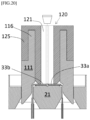
- FIG. 20 is a view schematically illustrating a state in which the electrode lead is welded to the bus bar via a welding space portion of the masking jig according to an embodiment of present disclosure.
- the present invention is not limited to the embodiments disclosed below, but will be variously changed and implemented in various different forms.
- the present embodiments are provided so that the present invention will be thorough and complete, and also to provide a more complete understanding of the scope of the present invention to those of ordinary skill in the art. Accordingly, it should be understood that the present invention is not limited to the embodiments disclosed below, but the configuration of any one embodiment and the configuration of another embodiment can be substituted or added, and the present invention includes all alterations, equivalents, and alternatives that are included in the technical spirit and scope of the present invention.
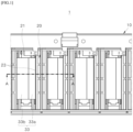
- FIG. 1 is a plan view schematically illustrating a secondary battery module according to the present invention
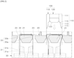
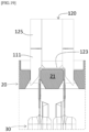
- FIG. 2 is a cross-sectional view schematically illustrating a state in which an electrode lead aligning and masking device is disposed on an upper side of a bus bar in the secondary battery module according to the present invention.
- a plurality of battery cells 30 are stacked inside a case 10.
- An electrode tab 31 extends to protrude from each of the battery cells 30, and is welded to an electrode lead 33.
- a bus bar frame 20 is assembled to a battery cell stack (not shown).
- a plurality of bus bars 21 are arranged side by side in the bus bar frame 20.
- a slot 23 is formed between each of the plurality of bus bars 21 in the bus bar frame 20.
- the slot 23 may be formed with a width that is about 5 to 7 times a thickness of the electrode lead 33.
- the electrode lead 33 is bent so as to come into close contact with the bus bar 21 using a bending tool (not shown) in a bending process.
- a pair of electrode leads 33 are bent in a width direction of the bus bar 21 and overlap each other.
- a welding process is performed.
- an electrode lead aligning and masking device 100 welds the bent electrode leads 33 to the bus bar 21 in a state in which the electrode leads 33 are aligned on the bus bar 21. This will be described in detail below.
- the electrode lead aligning and masking device 100 is a device for aligning and masking the electrode leads 33 bent on the bus bar 21 of the secondary battery module 1 in the welding process of the electrode leads 33.
- the electrode leads 33 having the same polarity may be bent or the electrode leads 33 having opposite polarities may be bent.
- the electrode leads 33 having the same polarity may be bent on some bus bars 21, and the electrode leads 33 having opposite polarities may be bent on the remaining bus bars 21.
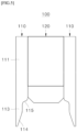
- FIG. 3 is a perspective view schematically illustrating an electrode lead aligning and masking device according to a first embodiment of the present invention
- FIG. 4 is an exploded perspective view schematically illustrating the electrode lead aligning and masking device according to the first embodiment of the present invention
- FIG. 5 is a front view schematically illustrating the electrode lead aligning and masking device according to the first embodiment of the present invention
- FIG. 6 is a view schematically illustrating a state in which the electrode lead aligning and masking device according to the first embodiment of the present invention is located on an upper side of an electrode lead
- FIG. 7 is a view schematically illustrating a state in which an alignment jig of the electrode lead aligning and masking device according to the first embodiment of the present invention is inserted into a slot to align the electrode lead.
- an electrode lead aligning and masking device 100 includes a pair of aligning jigs 110 and a masking jig 120.
- the pair of aligning jigs 110 are inserted into the slots 23 on both sides of the bus bar 21 and align positions of a pair of electrode leads 33.
- the pair of aligning jigs 110 gather the bent electrode leads 33 on both side surfaces of the bus bar 21 in the width direction while being inserted into the slots 23.
- the pair of electrode leads 33 may be aligned to be in close contact with or slightly spaced apart from both side surfaces of the bus bar 21 in the width direction.
- an end portion of one electrode lead 33 has a length so as to be spaced apart from a bent portion 34 of the other electrode lead 33 by a predetermined distance.
- the masking jig 120 is coupled to the aligning jigs 110 and is formed to surround a welding portion of the electrode lead 33.
- the masking jig 120 shields a circumference of the welding portion so that sparks or spatters do not deviate from the welding portion when the electrode lead 33 is welded to the bus bar 21. Accordingly, it is possible to significantly reduce a welding defect rate by preventing spatters or sparks generated during welding from splashing to a surrounding structure.
- the bent electrode leads 33 can be welded to a correct position of the bus bar 21.
- an actual welding length of the electrode lead 33 may be matched with a design welding length thereof.
- the welding length refers to a length at which the electrode lead is welded in parallel to a length of the bus bar 21 in the width direction.
- the electrode leads 33 may be prevented from spreading outward in the width direction of the bus bar 21. Accordingly, it is possible to prevent a bonding area and a bonding strength of the welding portion from being reduced and reduce a welding defect rate.
- the end portion of the bent electrode lead 33 does not overlap the bent portion 34 of the opposite electrode lead 33, which is bent to be rounded, it is possible to prevent an overlapping portion of the pair of electrode leads 33 from being locally lifted or prevent a gap from widening. Accordingly, the bonding strength of the welding portion can be increased.
- the pair of aligning jigs 110 are coupled to both sides of the masking jig 120 in the width direction.
- the pair of aligning jigs 110 may be welded or adhered to both sides of the masking jig 120 in the width direction or coupled to the both sides by fastening members such as screws or rivets. Accordingly, the aligning jigs 110 and the masking jig 120 may be lifted and moved by one moving device (not shown) to align and weld the electrode leads 33.
- the aligning jig 110 gathers the electrode lead 33 toward the bus bar 21 while being inserted into the slot 23 on an outer side of the electrode lead 33.
- outer sides of the pair of aligning jigs 110 in a thickness direction may be in contact with or be spaced apart from outer surfaces of the slot 23.
- inner sides of the pair of aligning jigs 110 in the thickness direction may be in contact with outer side surfaces of the electrode leads 33. Accordingly, when the aligning jig 110 descends, the pair of electrode leads 33 may be aligned while being gathered toward the bus bar 21.
- the aligning jig 110 includes an alignment body portion 111 and an alignment rib 113.
- the alignment bodies 111 face both sides of the masking jig 120.
- the alignment bodies 111 may be fixed to both sides of the masking jig 120 in the width direction by welding or an adhesive, or may be fixed to both sides of the masking jig 120 in the width direction by fastening members such as screws or rivets.
- the alignment rib 113 extends downward from the alignment body portion 111 and is formed to be thinner than a thickness of the alignment body portion 111.
- the alignment rib 113 aligns the electrode lead 33 while being inserted into the slot 23.
- the alignment rib 113 presses the outer side surfaces of the electrode lead 33 toward the bus bar 21 to bring the electrode lead 33 into close contact with the bus bar 21 or align the electrode lead 33 to be finely separated from the bus bar 21. Whether the electrode lead 33 is in contact with the bus bar 21 may be determined according to a thickness of the aligning jig.
- An alignment taper portion 114 is formed on an inner side of the alignment rib 113 in the thickness direction to gather the electrode lead 33 toward the bus bar 21.
- a thickness of the alignment rib 113 becomes gradually smaller toward the lower side due to the alignment taper portion 114. Accordingly, a lower end portion of the alignment rib 113 is easily inserted between the outer side surface of the electrode lead 33 and an outer side surface of the slot 23, and as the alignment rib 113 descends, the electrode lead 33 may be aligned while being pressed toward the bus bar 21.
- a stepped portion 115 may be formed on a lower side of the alignment body portion 111 to be spaced apart from the bent portion 34 of the electrode lead 33.
- a pressing surface portion 123 of the masking jig 120 is disposed at a lower position than the stepped portion 115.
- the stepped portion 115 may be formed to be horizontal or slightly inclined with respect to the pressing surface portion 123. Accordingly, when the pressing surface portion 123 of the masking jig 120 presses the electrode lead 33, the bent portion 34 of the electrode lead 33 is spaced apart from the stepped portion 115 by a predetermined distance, thereby preventing the alignment body portion 111 from pressing the bent portion 34 of the electrode lead 33. Furthermore, the electrode lead 33 or the electrode tab 31 may be prevented from being bent or broken by a pressing force of the alignment body portion 111.
- the aligning jig 110 is formed in the shape of a rectangular panel.
- a length of the aligning jig 110 may be formed to be slightly smaller than a length of the slot 23.
- the length of the aligning jig 110 may also be formed to be equal to or slightly larger than a length of the electrode lead 33.
- the aligning jig 110 may be formed in various shapes such as the shape of a sawtooth, the shape of a plurality of bars arranged in a row, and the like, as long as it is inserted into the slot 23 and aligns the electrode lead 33.
- a welding space portion 121 passing through the masking jig 120 in a vertical direction is formed in the masking jig 120.
- the welding tool may pass through the welding space portion 121 and weld the bent electrode lead 33 to the bus bar 21.
- the welding tool may be a laser welding tool that welds the electrode leads 33 by irradiating a laser thereto, or a spot welding tool that welds the electrode leads 33 by applying an electric current thereto.
- Various welding types may be applied according to the type of material of each of the electrode lead 33 and the bus bar 21. As described above, since the welding tool enters the welding space portion 121 to weld the electrode lead 33, it is possible to prevent spatters or welding sparks from splashing around the electrode lead 33.
- the masking jig 120 may be formed in the shape of a rectangular cylinder parallel to the bus bar 21 in the longitudinal direction.
- the welding space portion 121 is formed parallel to the bus bar 21 in the longitudinal direction.
- a width of the masking jig 120 may be formed smaller than a width of the bus bar 21.
- a width of the welding space portion 121 may be formed smaller than the width of the bus bar 21.
- a length of the welding space portion 121 may be formed to be slightly smaller than the length of the electrode lead 33.
- a cross section of the welding space portion 121 may be formed in a rectangular shape parallel to the bus bar 21 in the longitudinal direction. Since the masking jig 120 is formed in the shape of a rectangular cylinder, the overlapping portion of the electrode leads 33 may be welded in the longitudinal direction.
- the masking jig 120 presses the bent electrode leads 33 to the bus bar 21. Accordingly, when the welding tool welds the electrode leads 33, the overlapping portion of the electrode leads 33 may be prevented from being lifted or spaced. Furthermore, it is possible to prevent the welding bonding strength of the overlapping portion of the electrode leads 33 from being degraded. In addition, a local temperature deviation of the electrode lead 33 due to the lifting or spacing of the electrode lead 33 is prevented from occurring, thereby preventing a welding defect.
- the electrode lead aligning and masking device 100 may include a pair of aligning jigs 110 and one masking jig 120 to align a pair of electrode leads 33 to one bus bar 21.
- the electrode lead aligning and masking device 100 aligns and masks the electrode leads 33 on one bus bar 21 each time the electrode lead aligning and masking device 100 descends.
- the electrode lead aligning and masking device 100 may be manufactured in a form in which four or more aligning jigs 110 and two or more masking jigs 120 are arranged to align a pair of electrode leads 33 to each of at least two or more bus bars 21.
- the electrode lead aligning and masking device 100 may simultaneously align the electrode leads 33 to two or more bus bars 21 each time the electrode lead aligning and masking device 100 descends.
- FIG. 8 is an exploded perspective view schematically illustrating an electrode lead aligning and masking device according to a second embodiment of the present invention
- FIG. 9 is a perspective view schematically illustrating the electrode lead aligning and masking device according to the second embodiment of the present invention
- FIG. 10 is a front view schematically illustrating the electrode lead aligning and masking device according to the second embodiment of the present invention
- FIG. 11 is a cross-sectional view schematically illustrating a state in which the electrode lead aligning and masking device of FIG. 10 is cut along line 11-11
- FIG. 12 is a cross-sectional view schematically illustrating a state in which the electrode lead aligning and masking device of FIG. 11 is cut along line 12-12 in the electrode lead
- FIG. 13 is a cross-sectional view schematically illustrating a state in which the electrode lead aligning and masking device of FIG. 11 is cut along line 13-13 in the electrode lead.
- an electrode lead aligning and masking device 100 includes a pair of aligning jigs 110, a masking jig 120, and at least two elastic members 130.
- the pair of aligning jigs 110 are inserted into the slots 23 on both sides of the bus bar 21 and align positions of a pair of electrode leads 33.
- the pair of aligning jigs 110 gather the bent electrode leads 33 on both side surfaces of the bus bar 21 in the width direction while being inserted into the slots 23.
- the pair of electrode leads 33 may be aligned to be in close contact with or slightly spaced apart from both side surfaces of the bus bar 21 in the width direction.
- an end portion of one electrode lead 33 may have a length so as to be spaced apart from a bent portion 34 of the other electrode lead 33 by a predetermined distance.
- the masking jig 120 is disposed between the pair of aligning jigs 110 and is formed to surround a welding portion of the electrode lead 33.
- the aligning jigs 110 are movably coupled to the masking jig 120.
- the masking jig 120 shields a circumference of the welding portion so that sparks or spatters do not deviate from the welding portion when the electrode lead 33 is welded to the bus bar 21. Accordingly, it is possible to significantly reduce a welding defect rate by preventing spatters or sparks generated during welding from splashing to a surrounding structure.
- At least two elastic members 130 are installed on both sides of the masking jig 120 to elastically support the pair of aligning jigs 110.
- the elastic member 130 may be a coil spring configured to connect the masking jig 120 and the aligning jig 110.
- the elastic member 130 may applied in various forms and in various positions, as long as it elastically support the aligning jig 110.
- the aligning jig 110 is movably coupled to the masking jig 120 and is elastically supported by the elastic member 130. Accordingly, since the electrode leads 33 are aligned while the aligning jigs 110 move up and down, deformation of the electrode leads 33 may be minimized. In addition, since the impact of the aligning jig 110 and the electrode lead 33 is buffered at the moment when the aligning jig 110 presses the electrode lead 33, it is possible to prevent damage to the aligning jig 110 and the electrode lead 33. In addition, it is possible to prevent scratches from occurring on a surface of the electrode lead 33 and to significantly reduce the possibility of overheating and ignition of the electrode lead 33.
- the bent electrode leads 33 can be welded to a correct position of the bus bar 21.
- an actual welding length of the electrode lead 33 can be matched with a design welding length thereof.
- the welding length refers to a length at which the electrode lead is welded in parallel to a length of the bus bar 21 in the width direction.
- the electrode leads 33 may be prevented from spreading outward in the width direction of the bus bar 21. Accordingly, it is possible to prevent a bonding area and a bonding strength of the welding portion from being reduced and reduce a welding defect rate.
- the end portion of the bent electrode lead 33 does not overlap the bent portion 34 of the opposite electrode lead 33, which is bent to be rounded, it is possible to prevent an overlapping portion of the pair of electrode leads 33 from being locally lifted or prevent a gap from widening. Accordingly, a bonding strength of the welding portion can be increased.
- the masking jig 120 includes a masking body portion 122 and a sliding guide portion 125.
- a welding space portion 121 passing through the masking body portion 122 in the vertical direction is formed in the masking body portion 122.
- the welding space portion 121 may be formed in the shape of a long hole parallel to the masking body portion 122 in the longitudinal direction. Accordingly, the welding tool may approach and weld the electrode lead 33 via the welding space portion 121.
- the welding tool may be a laser welding tool that welds the electrode leads 33 by irradiating a laser thereto, or a spot welding tool that welds the electrode leads 33 by applying an electric current thereto.
- Various welding types may be applied according to the type of material of each of the electrode lead 33 and the bus bar 21. As described above, since the welding tool enters the welding space portion 121 to weld the electrode lead 33, it is possible to prevent spatters or welding sparks from splashing around the electrode lead 33.
- the sliding guide portions 125 are disposed on both sides of the masking body portion 122.
- a sliding groove portion 121 is formed in the sliding guide portion 125 such that the aligning jig 110 is slidably coupled to the sliding guide portion 125.
- the sliding groove portion 121 is a space surrounded by a side surface of the masking body portion 122 and an inner side surface of the sliding guide portion 125.
- the sliding groove portion 121 is formed in the shape of a long hole along a longitudinal direction of the masking body portion 122. In addition, a lower side of the sliding groove portion 121 is open.
- the sliding guide portion 125 supports the aligning jig 110 so that the aligning jig 110 does not move.
- the aligning jig 110 gathers the electrode lead 33 toward the bus bar 21 while being inserted into the slot 23 on an outer side of the electrode lead 33.
- outer sides of the pair of aligning jigs 110 in a thickness direction may be in contact with or be spaced apart from outer side surfaces of the slots 23.
- inner sides of the pair of aligning jigs 110 in the thickness direction may be in contact with outer side surfaces of the electrode leads 33. Accordingly, when the aligning jig 110 descends, the pair of electrode leads 33 may be aligned while being gathered toward the bus bar 21.
- the aligning jig 110 includes an alignment body portion 111, an alignment rib 113, and a slider 116.
- the aligning jig 110 may be entirely formed in the shape of a rectangular panel.
- the alignment bodies 111 face both sides of the masking jig 120.
- An inner side surface of the alignment body portion 111 is formed in a flat plate shape so as to be in surface contact with a side surface of the masking jig 120 when the aligning jig 110 moves in the vertical direction.
- the alignment rib 113 extends downward from the alignment body portion 111 and is formed to be thinner than a thickness of the alignment body portion 111.
- the alignment rib 110 align the electrode lead 33 by being inserted into the slot 23 between the bus bars 21.
- the alignment rib 110 may be formed to have the same length as or a slightly different length from the alignment body portion 122.
- the slider 116 extends upward from the alignment body portion 111 and is slidably coupled to the sliding groove portion 126.
- the slider 116 may be formed in a plate shape so as to be inserted into the sliding groove portion 126.
- a length of the slider 116 may be formed to be slightly smaller than a length of the sliding groove portion 126.
- a thickness of the slider 116 may be formed smaller than a thickness of the alignment body portion 111. Accordingly, a lower end portion of the slider 116 and an upper end portion of the alignment body portion 111 may be formed to be stepped. In addition, since the thickness of the slider 116 is formed to be small, a width of the sliding guide portion 125 and a width of the sliding groove portion 126 may be prevented from increasing unnecessarily.
- An alignment taper portion 114 is formed on an inner side of the alignment rib 113 in the thickness direction to gather the electrode lead 33 toward the bus bar 21.
- a thickness of the alignment rib 113 becomes gradually smaller toward the lower side due to the alignment taper portion 114. Accordingly, a lower end portion of the alignment rib 113 is easily inserted between the outer side surface of the electrode lead 33 and an outer side surface of the slot 23, and as the alignment rib 113 descends, the electrode lead 33 may be aligned while being pressed toward the bus bar 21.
- a movement limiting portion 112 configured to limit a movement distance of the aligning jig 110 by being caught on a lower end portion of the sliding guide portion 125 is formed on an upper side of the alignment body portion 111.
- the movement limiting portion 112 may be a step formed at a boundary between the upper end portion of the alignment body portion 111 and the lower end portion of the slider 116.
- the movement limiting portion 112 may be formed in various structures on the alignment body portion 111 or the slider 116.
- a stepped portion 115 may be formed on a lower side of the alignment body portion 111 to be spaced apart from the bent portion 34 of the electrode lead 33.
- a pressing surface portion 123 of the masking jig 120 is disposed at a lower position than the stepped portion 115.
- the stepped portion 115 may be formed to be horizontal or slightly inclined with respect to the pressing surface portion 123. Accordingly, when the pressing surface portion 123 of the masking jig 120 presses the electrode lead 33, the bent portion 34 of the electrode lead 33 is spaced apart from the stepped portion 115 by a predetermined distance, thereby preventing the alignment body portion 111 from pressing the bent portion 34 of the electrode lead 33. Furthermore, the electrode lead 33 or the electrode tab 31 may be prevented from being bent or broken by a pressing force of the alignment body portion 111.
- a length of the aligning jig 110 may be formed to be slightly smaller than a length of the slot 23.
- the length of the aligning jig 110 may also be formed to be equal to or slightly larger than a length of the electrode lead 33.
- the aligning jig 110 may be formed in various shapes such as the shape of a sawtooth, the shape of a plurality of bars arranged in a row, and the like, as long as it is inserted into the slot 23 and aligns the electrode lead 33.
- the masking jig 120 may be formed in the shape of a rectangular cylinder parallel to the bus bar 21 in the longitudinal direction.
- a width of the masking jig 120 may be formed smaller than a width of the bus bar 21.
- a width of the welding space portion 121 may be formed smaller than the width of the bus bar 21.
- a length of the welding space portion 121 may be formed to be slightly smaller than the length of the electrode lead 33.
- a cross section of the welding space portion 121 may be formed in a rectangular shape parallel to the bus bar 21 in the longitudinal direction. Since the masking jig 120 is formed in the shape of a rectangular cylinder, the overlapping portion of the electrode leads 33 may be welded in the longitudinal direction.
- the masking jig 120 presses the bent electrode leads 33 on the bus bar 21. Accordingly, when the welding tool welds the electrode leads 33, the overlapping portion of the electrode leads 33 may be prevented from being lifted or spaced. Furthermore, it is possible to prevent the welding bonding strength of the overlapping portion of the electrode leads 33 from being degraded. In addition, a local temperature deviation of the electrode lead 33 due to the lifting or spacing of the electrode lead 33 is prevented from occurring, thereby preventing a welding defect.
- the elastic member 130 may be supported by the upper end portion of the alignment body portion 111 and an upper end portion of the sliding groove portion 126.
- the elastic members 130 may be disposed on both sides of the alignment body portion 111, respectively, in the longitudinal direction. Since the elastic members 130 are disposed on both sides of the alignment body portion 111 in the longitudinal direction, the aligning jig 110 may be finely inclined to one side in the longitudinal direction. Accordingly, even when the electrode lead 33 or the bus bar 21 is slightly inclined, the electrode lead 33 may be aligned as the aligning jig 110 is finely inclined to one side in the longitudinal direction.
- the electrode lead aligning and masking device 100 may include a pair of aligning jigs 110 and one masking jig 120 to align a pair of electrode leads 33 to one bus bar 21.
- the electrode lead aligning and masking device 100 aligns and masks the electrode leads 33 on one bus bar 21 each time the electrode lead aligning and masking device 100 descends.
- the electrode lead aligning and masking device 100 may be manufactured in a form in which four or more aligning jigs 110 and two or more masking jigs 120 are arranged to align a pair of electrode leads 33 to each of at least two or more bus bars 21.
- the electrode lead aligning and masking device 100 may simultaneously align the electrode leads 33 to two or more bus bars 21 each time the electrode lead aligning and masking device 100 descends.
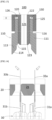
- FIG. 14 is a cross-sectional view schematically illustrating a state in which the electrode lead of the battery cell is inserted into the slot of the bus bar in the secondary battery module according to the present invention
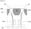
- FIG. 15 is a cross-sectional view schematically illustrating a state in which the electrode lead of the battery cell is bent on the bus bar in the secondary battery module according to the present invention
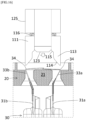
- FIG. 16 is a cross-sectional view schematically illustrating a state in which the aligning and masking device according to the present invention is located on an upper side of the bus bar
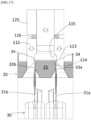
- FIG. 17 is a cross-sectional view schematically illustrating a state in which the aligning jig of the aligning and masking device according to the present invention is inserted into the slot between the bus bars
- FIG. 18 is a cross-sectional view schematically illustrating a state in which the stepped portion of the aligning jig the aligning and masking device according to the present invention presses the bent portion of the electrode lead
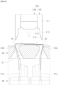
- FIG. 19 is a cross-sectional view schematically illustrating a state in which the pressing surface portion of the masking jig of the aligning and masking device according to the present invention presses the electrode lead
- FIG. 20 is a view schematically illustrating a state in which the electrode lead is welded to the bus bar via the welding space portion of the masking jig according to the present invention.
- the electrode leads 33 of the battery cell 30 are inserted into the slots 23 on both sides of the bus bar 21.
- the electrode leads 33 may be vertically inserted on both sides of the bus bar 21.
- a bending device presses and bends the electrode lead 33 toward the bus bar 21.
- the pair of electrode leads 33 may be spread toward both sides of the bus bar 21 or may be spaced apart from each other on both side surfaces of the bus bar 21 (see FIG. 15 ).
- the aligning and masking device 100 is moved to an upper side of the bus bar 21. At this time, the aligning jig 110 maintains the state of being most descended from the sliding guide portion 25 by an elastic force of the elastic member 130.
- the aligning jigs 110 are inserted into the slots 23 on both sides of the bus bar 21.
- the impact applied to the electrode lead 33 is buffered as the elastic member 130 is slightly contracted.
- the alignment taper portion 114 of the aligning jig 110 gently descends while sliding along the bent portion 34 of the electrode lead 33.
- the electrode lead 33 is gathered toward the bus bar 21 as the alignment taper portion 114 presses an outer side of the electrode lead 33.
- the electrode leads 33 are in close contact with both side surfaces of the bus bar 21 (see FIG. 17 ).
- the electrode lead 33 may be lifted or spaced apart from an upper surface of the bus bar 21.
- the stepped portion 115 of the aligning jig 110 is in close contact with the bent portion 34 of the electrode lead 33 ( FIG. 18 ). At this time, a pressing force of the aligning and masking device 100 is applied to the bent portion 34 of the electrode lead 33.
- the masking jig 120 descends in a state in which the stepped portion 115 of the aligning jig 110 is caught on the bent portion 34 of the electrode lead 33.
- the elastic member 130 is contracted in the longitudinal direction.
- the electrode lead 33 is brought into close contact with the upper surface of the bus bar 21.
- the welding tool welds the electrode lead 33 to the upper surface of the bus bar 21 via the welding space portion 121 of the masking jig 120 see ( FIG. 20 ). Accordingly, the electrode lead 33 may be welded to the bus bar 21 in a state in which the electrode lead 33 is brought into close contact with both side surfaces and the upper surface of the bus bar 21.
Landscapes
- Chemical & Material Sciences (AREA)
- Chemical Kinetics & Catalysis (AREA)
- Electrochemistry (AREA)
- General Chemical & Material Sciences (AREA)
- Engineering & Computer Science (AREA)
- Mechanical Engineering (AREA)
- Physics & Mathematics (AREA)
- Optics & Photonics (AREA)
- Manufacturing & Machinery (AREA)
- Connection Of Batteries Or Terminals (AREA)
- Fixed Capacitors And Capacitor Manufacturing Machines (AREA)
Applications Claiming Priority (2)
| Application Number | Priority Date | Filing Date | Title |
|---|---|---|---|
| KR20220022936 | 2022-02-22 | ||
| PCT/KR2023/002396 WO2023163469A1 (ko) | 2022-02-22 | 2023-02-20 | 전극리드 정렬 마스킹 장치 |
Publications (3)
| Publication Number | Publication Date |
|---|---|
| EP4456311A1 true EP4456311A1 (de) | 2024-10-30 |
| EP4456311A4 EP4456311A4 (de) | 2025-04-30 |
| EP4456311B1 EP4456311B1 (de) | 2026-04-01 |
Family
ID=87766401
Family Applications (1)
| Application Number | Title | Priority Date | Filing Date |
|---|---|---|---|
| EP23760343.6A Active EP4456311B1 (de) | 2022-02-22 | 2023-02-20 | Vorrichtung zur maskierung und ausrichtung von elektrodenleitungen |
Country Status (6)
| Country | Link |
|---|---|
| US (1) | US20250065448A1 (de) |
| EP (1) | EP4456311B1 (de) |
| JP (1) | JP7732724B2 (de) |
| KR (1) | KR20230126199A (de) |
| CN (1) | CN118743101A (de) |
| WO (1) | WO2023163469A1 (de) |
Families Citing this family (2)
| Publication number | Priority date | Publication date | Assignee | Title |
|---|---|---|---|---|
| JP7742445B1 (ja) * | 2024-03-29 | 2025-09-19 | 本田技研工業株式会社 | バスバークランプ装置およびバスバークランプ方法 |
| JP7741919B1 (ja) * | 2024-03-29 | 2025-09-18 | 本田技研工業株式会社 | バスバークランプ装置 |
Family Cites Families (10)
| Publication number | Priority date | Publication date | Assignee | Title |
|---|---|---|---|---|
| JP6011876B2 (ja) * | 2013-09-13 | 2016-10-19 | 株式会社オートネットワーク技術研究所 | 蓄電モジュール |
| KR101866614B1 (ko) * | 2015-03-09 | 2018-06-11 | 주식회사 엘지화학 | 레이저 용접용 지그를 이용한 레이저 용접 방법 |
| KR102090787B1 (ko) * | 2017-01-11 | 2020-03-18 | 주식회사 엘지화학 | 레이저 용접용 지그 어셈블리 |
| KR102157377B1 (ko) * | 2017-05-25 | 2020-09-17 | 주식회사 엘지화학 | 배터리 모듈, 이를 포함하는 배터리 팩 및 배터리 모듈 생산 방법 |
| KR102155888B1 (ko) * | 2017-09-11 | 2020-09-14 | 주식회사 엘지화학 | 레이저 용접 지그 및 이를 포함하는 레이저 용접 장치 |
| KR20190097614A (ko) | 2018-02-12 | 2019-08-21 | 전광훈 | 포토 만년인 제작 서비스 방법 및 시스템 |
| KR102258176B1 (ko) | 2018-06-22 | 2021-07-16 | 주식회사 엘지에너지솔루션 | 전극 리드를 버스바에 밀착시키는 자동 가압 지그 장치 및 이를 포함하는 배터리 모듈 제조 시스템 |
| KR102846625B1 (ko) * | 2019-08-22 | 2025-08-19 | (주)제이앤디테크 | 이차전지 제조장치 및 그에 사용되는 가압모듈 |
| KR102798151B1 (ko) * | 2020-01-02 | 2025-04-17 | 주식회사 엘지에너지솔루션 | 용접 대상물들의 밀착력을 향상시킬 수 있는 가압 지그 |
| KR102426676B1 (ko) | 2020-08-19 | 2022-07-28 | 한양대학교 산학협력단 | 미세섬유 기반의 멤브레인 및 이의 제조방법 |
-
2023
- 2023-02-20 JP JP2024539989A patent/JP7732724B2/ja active Active
- 2023-02-20 EP EP23760343.6A patent/EP4456311B1/de active Active
- 2023-02-20 US US18/728,631 patent/US20250065448A1/en active Pending
- 2023-02-20 KR KR1020230022109A patent/KR20230126199A/ko active Pending
- 2023-02-20 WO PCT/KR2023/002396 patent/WO2023163469A1/ko not_active Ceased
- 2023-02-20 CN CN202380023209.7A patent/CN118743101A/zh active Pending
Also Published As
| Publication number | Publication date |
|---|---|
| CN118743101A (zh) | 2024-10-01 |
| US20250065448A1 (en) | 2025-02-27 |
| JP2024546352A (ja) | 2024-12-19 |
| JP7732724B2 (ja) | 2025-09-02 |
| KR20230126199A (ko) | 2023-08-29 |
| EP4456311A4 (de) | 2025-04-30 |
| WO2023163469A1 (ko) | 2023-08-31 |
| EP4456311B1 (de) | 2026-04-01 |
Similar Documents
| Publication | Publication Date | Title |
|---|---|---|
| EP3367468B1 (de) | Zusammengesetzte batterie und verfahren zur herstellung der zusammengesetzten batterie | |
| CN110087825B (zh) | 激光焊接夹具和包含该激光焊接夹具的激光焊接设备 | |
| US11050107B2 (en) | Method for assembling battery pack, and battery pack | |
| EP4456311A1 (de) | Vorrichtung zur maskierung der ausrichtung von elektrodenleitungen | |
| KR102165327B1 (ko) | 전극 리드 밀착용 지그 및 전극 리드 용접 방법 | |
| US10553840B2 (en) | Manufacturing method and manufacturing device for battery pack | |
| EP2341568A1 (de) | Batteriemodul mit eine Mehrzal von Batteriezellen und dazugehörige Verbindungselemente | |
| KR20210048096A (ko) | 이차전지 탭 레이저 용접을 위한 밀착 지그 및 용접 방법 | |
| US20190341594A1 (en) | Battery pack, busbar holder used for battery pack, and method for manufacturing battery pack | |
| KR20160007109A (ko) | 전극 조립체의 복수개의 전극 탭과 전극 리드의 연결부의 포밍 방법 및 이를 이용하여 제조된 이차 전지 | |
| US20190372079A1 (en) | Battery pack production method and production device | |
| US12491588B2 (en) | Welding positioning apparatus, battery production line, and welding method | |
| KR20200058173A (ko) | 이차 전지 | |
| KR20250031169A (ko) | 용접성이 향상된 전지 셀 및 이의 가공 장치 | |
| KR100749477B1 (ko) | 이차 전지의 캡 플레이트 용접용 지그 | |
| KR20200085173A (ko) | 2차 전지 조립용 가변형 코킹장치 | |
| KR102921155B1 (ko) | 각형 이차전지 포일 벤딩 장치 및 포일 벤딩 방법 | |
| EP4604262A1 (de) | Testvorrichtung zum thermischen durchgehen für batterien | |
| KR20250160757A (ko) | 배터리 모듈 및 이의 제조 방법 | |
| US20230198103A1 (en) | Manufacturing method of battery pack | |
| EP4498492A1 (de) | Batteriemodul und montageverfahren dafür | |
| KR20260001790A (ko) | 전극조립체 제조장치 및 전극조립체 제조방법 | |
| KR20250145751A (ko) | 이차전지 및 이의 제조방법 | |
| KR20250057343A (ko) | 배터리용 용접 버 제거장치 | |
| KR20260019780A (ko) | 버스바, 버스바를 포함하는 배터리조립체 및 배터리조립체의 제조방법 |
Legal Events
| Date | Code | Title | Description |
|---|---|---|---|
| STAA | Information on the status of an ep patent application or granted ep patent |
Free format text: STATUS: THE INTERNATIONAL PUBLICATION HAS BEEN MADE |
|
| PUAI | Public reference made under article 153(3) epc to a published international application that has entered the european phase |
Free format text: ORIGINAL CODE: 0009012 |
|
| STAA | Information on the status of an ep patent application or granted ep patent |
Free format text: STATUS: REQUEST FOR EXAMINATION WAS MADE |
|
| 17P | Request for examination filed |
Effective date: 20240722 |
|
| AK | Designated contracting states |
Kind code of ref document: A1 Designated state(s): AL AT BE BG CH CY CZ DE DK EE ES FI FR GB GR HR HU IE IS IT LI LT LU LV MC ME MK MT NL NO PL PT RO RS SE SI SK SM TR |
|
| A4 | Supplementary search report drawn up and despatched |
Effective date: 20250327 |
|
| RIC1 | Information provided on ipc code assigned before grant |
Ipc: B23K 101/38 20060101ALN20250321BHEP Ipc: B23K 101/36 20060101ALI20250321BHEP Ipc: B23K 37/04 20060101ALI20250321BHEP Ipc: H01M 50/557 20210101ALI20250321BHEP Ipc: H01M 50/502 20210101ALI20250321BHEP Ipc: H01M 50/516 20210101AFI20250321BHEP |
|
| DAV | Request for validation of the european patent (deleted) | ||
| DAX | Request for extension of the european patent (deleted) | ||
| RIC1 | Information provided on ipc code assigned before grant |
Ipc: H01M 50/516 20210101AFI20250813BHEP Ipc: H01M 50/502 20210101ALI20250813BHEP Ipc: H01M 50/557 20210101ALI20250813BHEP Ipc: B23K 37/04 20060101ALI20250813BHEP Ipc: B23K 101/36 20060101ALI20250813BHEP Ipc: B23K 101/38 20060101ALN20250813BHEP |
|
| RIC1 | Information provided on ipc code assigned before grant |
Ipc: H01M 50/516 20210101AFI20250908BHEP Ipc: H01M 50/502 20210101ALI20250908BHEP Ipc: H01M 50/557 20210101ALI20250908BHEP Ipc: B23K 37/04 20060101ALI20250908BHEP Ipc: B23K 101/36 20060101ALI20250908BHEP Ipc: B23K 101/38 20060101ALN20250908BHEP |
|
| GRAP | Despatch of communication of intention to grant a patent |
Free format text: ORIGINAL CODE: EPIDOSNIGR1 |
|
| STAA | Information on the status of an ep patent application or granted ep patent |
Free format text: STATUS: GRANT OF PATENT IS INTENDED |
|
| RIC1 | Information provided on ipc code assigned before grant |
Ipc: H01M 50/516 20210101AFI20250930BHEP Ipc: H01M 50/502 20210101ALI20250930BHEP Ipc: H01M 50/557 20210101ALI20250930BHEP Ipc: B23K 37/04 20060101ALI20250930BHEP Ipc: B23K 101/36 20060101ALI20250930BHEP Ipc: B23K 101/38 20060101ALN20250930BHEP |
|
| INTG | Intention to grant announced |
Effective date: 20251023 |
|
| P01 | Opt-out of the competence of the unified patent court (upc) registered |
Free format text: CASE NUMBER: UPC_APP_0012226_4456311/2025 Effective date: 20251105 |
|
| GRAS | Grant fee paid |
Free format text: ORIGINAL CODE: EPIDOSNIGR3 |
|
| GRAA | (expected) grant |
Free format text: ORIGINAL CODE: 0009210 |
|
| STAA | Information on the status of an ep patent application or granted ep patent |
Free format text: STATUS: THE PATENT HAS BEEN GRANTED |